EP4247647B1 - Radkappe für metallrad, metallrad mit einer derartigen radkappe und rzeug mit einem derartigen rad - Google Patents
Radkappe für metallrad, metallrad mit einer derartigen radkappe und rzeug mit einem derartigen rad Download PDFInfo
- Publication number
- EP4247647B1 EP4247647B1 EP21798739.5A EP21798739A EP4247647B1 EP 4247647 B1 EP4247647 B1 EP 4247647B1 EP 21798739 A EP21798739 A EP 21798739A EP 4247647 B1 EP4247647 B1 EP 4247647B1
- Authority
- EP
- European Patent Office
- Prior art keywords
- wheel
- holding part
- trim
- groove
- rim
- Prior art date
- Legal status (The legal status is an assumption and is not a legal conclusion. Google has not performed a legal analysis and makes no representation as to the accuracy of the status listed.)
- Active
Links
Images

Classifications
-
- B—PERFORMING OPERATIONS; TRANSPORTING
- B60—VEHICLES IN GENERAL
- B60B—VEHICLE WHEELS; CASTORS; AXLES FOR WHEELS OR CASTORS; INCREASING WHEEL ADHESION
- B60B7/00—Wheel cover discs, rings, or the like, for ornamenting, protecting, venting, or obscuring, wholly or in part, the wheel body, rim, hub, or tyre sidewall, e.g. wheel cover discs, wheel cover discs with cooling fins
- B60B7/04—Wheel cover discs, rings, or the like, for ornamenting, protecting, venting, or obscuring, wholly or in part, the wheel body, rim, hub, or tyre sidewall, e.g. wheel cover discs, wheel cover discs with cooling fins built-up of several main parts
-
- B—PERFORMING OPERATIONS; TRANSPORTING
- B60—VEHICLES IN GENERAL
- B60B—VEHICLE WHEELS; CASTORS; AXLES FOR WHEELS OR CASTORS; INCREASING WHEEL ADHESION
- B60B7/00—Wheel cover discs, rings, or the like, for ornamenting, protecting, venting, or obscuring, wholly or in part, the wheel body, rim, hub, or tyre sidewall, e.g. wheel cover discs, wheel cover discs with cooling fins
-
- B—PERFORMING OPERATIONS; TRANSPORTING
- B60—VEHICLES IN GENERAL
- B60B—VEHICLE WHEELS; CASTORS; AXLES FOR WHEELS OR CASTORS; INCREASING WHEEL ADHESION
- B60B7/00—Wheel cover discs, rings, or the like, for ornamenting, protecting, venting, or obscuring, wholly or in part, the wheel body, rim, hub, or tyre sidewall, e.g. wheel cover discs, wheel cover discs with cooling fins
- B60B7/06—Fastening arrangements therefor
- B60B7/061—Fastening arrangements therefor characterised by the part of the wheels to which the discs, rings or the like are mounted
- B60B7/063—Fastening arrangements therefor characterised by the part of the wheels to which the discs, rings or the like are mounted to the rim
-
- B—PERFORMING OPERATIONS; TRANSPORTING
- B60—VEHICLES IN GENERAL
- B60B—VEHICLE WHEELS; CASTORS; AXLES FOR WHEELS OR CASTORS; INCREASING WHEEL ADHESION
- B60B7/00—Wheel cover discs, rings, or the like, for ornamenting, protecting, venting, or obscuring, wholly or in part, the wheel body, rim, hub, or tyre sidewall, e.g. wheel cover discs, wheel cover discs with cooling fins
- B60B7/06—Fastening arrangements therefor
- B60B7/061—Fastening arrangements therefor characterised by the part of the wheels to which the discs, rings or the like are mounted
- B60B7/065—Fastening arrangements therefor characterised by the part of the wheels to which the discs, rings or the like are mounted to the disc
-
- B—PERFORMING OPERATIONS; TRANSPORTING
- B60—VEHICLES IN GENERAL
- B60B—VEHICLE WHEELS; CASTORS; AXLES FOR WHEELS OR CASTORS; INCREASING WHEEL ADHESION
- B60B7/00—Wheel cover discs, rings, or the like, for ornamenting, protecting, venting, or obscuring, wholly or in part, the wheel body, rim, hub, or tyre sidewall, e.g. wheel cover discs, wheel cover discs with cooling fins
- B60B7/06—Fastening arrangements therefor
- B60B7/08—Fastening arrangements therefor having gripping elements consisting of formations integral with the cover
-
- B—PERFORMING OPERATIONS; TRANSPORTING
- B60—VEHICLES IN GENERAL
- B60B—VEHICLE WHEELS; CASTORS; AXLES FOR WHEELS OR CASTORS; INCREASING WHEEL ADHESION
- B60B2310/00—Manufacturing methods
- B60B2310/30—Manufacturing methods joining
- B60B2310/306—Manufacturing methods joining by clamping or wedging, e.g. by clamping inserts as joining means
-
- B—PERFORMING OPERATIONS; TRANSPORTING
- B60—VEHICLES IN GENERAL
- B60B—VEHICLE WHEELS; CASTORS; AXLES FOR WHEELS OR CASTORS; INCREASING WHEEL ADHESION
- B60B2900/00—Purpose of invention
- B60B2900/50—Improvement of
- B60B2900/572—Visual appearance
Definitions
- the present invention relates to an assembly composed of a hubcap for a sheet metal wheel and a sheet metal wheel comprising such a hubcap. According to a second aspect, the invention relates to a vehicle comprising such a sheet metal wheel equipped with such a hubcap.
- the present invention relates more particularly to such a hubcap for a sheet metal wheel of the type comprising a rim which has a web in its center, the web comprising a series of openings at the edge of the rim, said hubcap being positioned at the level of one of said openings and comprising a first holding part which is adapted to bear against an edge of said opening.
- the document FR-A1-3093673 discloses such a hubcap for a sheet metal wheel of the type comprising a rim which has a web in its center, the web comprising a series of openings at the edge of the rim where hubcaps are positioned at part of the openings, the hubcaps comprising a first holding part which is adapted to bear against an edge of the corresponding opening.
- Such a hubcap due to its sole support along the edge of the opening of the steel rim, may be poorly positioned or rotate on itself when the vehicle is moving and cause a vibration and aesthetic problem for the wheel.
- the device according to the invention makes it possible to overcome this drawback.
- the rim of the sheet metal wheel has a curved free edge forming a groove, the second part for holding the hubcap having a shape complementary to said groove to rest in said groove.
- the rim has a second groove at the edge of the veil, the groove formed by said free edge forming a first groove, the second part for holding the hubcap having a shape complementary to the first groove and to the second groove, allowing the second part for holding the hubcap to rest in each of the two grooves.
- the first holding part is adapted to deform elastically when mounting the hubcap on the wheel.
- the first holding part comprises a curved part which has a U-shaped profile, said U-shaped profile being adapted to grip the edge of the opening.
- the free ends of the curved part comprise gripping means facilitating the elastic deformation of said first part of the hubcap.
- an intermediate part connects the first holding part to the second holding part, said intermediate part having a shape adapted to be able to deform elastically in a preferred direction, making it possible to bring the first holding part closer to the second holding part.
- the trim comprises a technical part and a trim part, the trim part being clipped onto the technical part.
- technical and the technical part comprising the first holding part and the second holding part.
- FIG. 1 represents a sheet metal wheel 1 which has a rim 11 with a disc 12 in its center.
- the rim 11 has a first groove 13 which is formed by a curved outer free edge and a second groove 14 which is positioned at the edge of the rim 11 with the web 12.
- the veil 12 comprises a series of openings 15 which are formed at the edge of the veil 12 and the rim 11, hubcaps 2 are positioned at the level of a part of these openings 15, partially masking them.
- trim 2 only one opening 15 out of two is masked by a trim 2, but depending on the proximity of the openings 15 and the size of the trims 2, there may be more or fewer trims 2.
- FIG. 2 represents a partial view, in section, of the wheel 1 at the level of one of the hubcaps 2.
- the hubcap 2 comprises at least two retaining parts, a first retaining part 21 which is adapted to bear against an edge of the opening 15 and a second retaining part 22 which is adapted to bear against the rim 11.
- the second holding part 22 of the hubcap 2 has a shape complementary to the first groove 13 and the second groove 14, allowing it to rest in each of the two grooves.
- the second holding part 22 comprises a first part 221 which follows the curvature of the rim 11 to stabilize itself well in the first groove 13 and which has an arc-shaped profile to fit well with the arc-shaped profile of the first groove 13.
- the second holding part 22 comprises a second part 222 which, like the first part 221, takes up the curvature of the rim 11 to stabilize itself well in the second groove 14 and which has an arc-shaped profile to fit well with the arc-shaped profile of the second groove 14.
- the second holding portion 22 comprises a connecting portion 223 which rigidly connects the first portion 221 and the second portion 222.
- the first holding part 21 is adapted to deform elastically when mounting the hubcap 2 on the wheel 1.
- the first holding part 21 comprises a linear part 211 which forms a double curved rail with a U-shaped section, adapted to grip the edge of the opening 15.
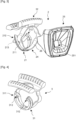
- FIG. 3 represents a hubcap 2 with a technical part 24 and a trim part 25 which are represented before assembling them.
- the technical part 24 consists of the first holding part 21, the second holding part 22 and an intermediate part 26.
- the intermediate part 26 has a shape adapted to be able to deform elastically in a preferred direction, making it possible to bring the first holding part 21 of the second holding part 22 when positioning the hubcap 2 in the corresponding opening 15.
- the covering part 25 is clipped onto the technical part 24, hiding the various holding parts, while retaining a central opening 251 which makes it possible to maintain an air circulation flow for cooling the braking device.
- the first holding part 21 comprises at the free ends 212 of the double curved rail 211 gripping means 213 which facilitate the elastic deformation of the double curved rail 211.
- the gripping means 213 of the first holding part 21 are formed by two fingers which can be easily gripped by the hand of an operator when mounting the hubcap 2 on the wheel 1 and this without special tools.
- FIG. 4 On the figure 4 a second embodiment of gripping means 311 of a first holding part 31 of a hubcap 3 is shown.
- the first holding part 31 requires the use of a clamp in order to rest in openings 312 formed in each of the two gripping means 311 in order to be able to elastically deform the first holding part 31 and insert it into one of the openings in the sheet metal wheel web.
Landscapes
- Engineering & Computer Science (AREA)
- Mechanical Engineering (AREA)
- Connection Of Plates (AREA)
- Insertion Pins And Rivets (AREA)
Claims (8)
- Anordnung mit einer Zierkappe (2, 3) und einem Blechrad (1), wobei das Blechrad (1) eine Felge (11) aufweist, die in ihrer Mitte einen Steg (12) aufweist, wobei der Steg (12) eine Reihe von Öffnungen (15) am Rand des Stegs (11) aufweist, wobei die Zierkappe (2, 3) an einer der Öffnungen (15) angeordnet ist und einen ersten Halteabschnitt (21, 31) aufweist, der geeignet ist, sich gegen einen Rand der Öffnung (15), der Zierkappe (2, abzustützen, 3) mit mindestens einem zweiten Halteteil (22), das geeignet ist, sich an der Felge (11) abzustützen, dadurch gekennzeichnet, dass die Felge (11) des Blechrads (1) einen gebogenen freien Rand aufweist, der eine Nut (13) bildet, wobei der zweite Halteteil (22) der Zierkappe (2, 3) eine zu der Nut (13) komplementäre Form aufweist, um sich in der Nut (13) abzustützen.
- Anordnung nach Anspruch 1, dadurch gekennzeichnet, dass die Felge (11) am Rand des Vlieses (12) eine zweite Nut (14) aufweist, wobei die von dem freien Rand gebildete Nut (13) eine erste Nut bildet, wobei der zweite Halteabschnitt (22) der Zierkappe (2, 3) eine Form aufweist, die komplementär zu der ersten Nut (13) und der zweiten Nut (14) ist, wodurch der zweite Halteabschnitt (22) der Zierkappe (2, 3) in jeder der beiden Nuten (13, 14) zur Anlage kommen kann.
- Anordnung nach Anspruch 2, dadurch gekennzeichnet, dass das erste Halteteil (21, 31) angepasst ist, um sich beim Anbringen der Zierkappe (2, 3) an dem Rad (1) elastisch zu verformen.
- Anordnung nach Anspruch 3, dadurch gekennzeichnet, dass der erste Halteabschnitt (21, 31) einen gekrümmten Abschnitt (211) aufweist, der ein U-Profil aufweist, wobei das U-Profil angepasst ist, um den Rand der Öffnung (15) einzuklemmen.
- Anordnung nach Anspruch 4, dadurch gekennzeichnet, dass die freien Enden (212) des gekrümmten Abschnitts (211) Greifmittel (213, 311) aufweisen, die die elastische Verformung des ersten Abschnitts der Zierkappe erleichtern.
- Anordnung nach einem der vorhergehenden Ansprüche, dadurch gekennzeichnet, dass ein Zwischenabschnitt (26) den ersten Halteabschnitt (21, 31) mit dem zweiten Halteabschnitt (22) verbindet, wobei der Zwischenabschnitt (26) eine Form aufweist, die geeignet ist, sich elastisch in einer bevorzugten Richtung verformen zu können, die es ermöglicht, den ersten Halteabschnitt (21, 31) näher an den zweiten Halteabschnitt (22) heranzuführen.
- Anordnung nach einem der vorhergehenden Ansprüche, dadurch gekennzeichnet, dass die Zierkappe (2, 3) einen technischen Teil (24) und einen Verkleidungsteil (25) aufweist, wobei der Verkleidungsteil (25) an den technischen Teil (24) angeklipst ist und der technische Teil (24) den ersten Halteteil (21, 31) und den zweiten Halteteil (22) aufweist.
- Fahrzeug, das zusammen eine Zierkappe (2, 3) und ein Blechrad (1) nach einem der vorhergehenden Ansprüche aufweist.
Priority Applications (1)
| Application Number | Priority Date | Filing Date | Title |
|---|---|---|---|
| MA62234A MA62234B1 (fr) | 2020-11-19 | 2021-09-29 | Enjoliveur pour une roue en tôle, roue en tôle comportant un tel enjoliveur et véhicule comportant une telle roue |
Applications Claiming Priority (2)
| Application Number | Priority Date | Filing Date | Title |
|---|---|---|---|
| FR2011865A FR3116232B1 (fr) | 2020-11-19 | 2020-11-19 | Enjoliveur pour une roue en tole, roue en tole comportant un tel enjoliveur et vehicule comportant une telle roue |
| PCT/FR2021/051678 WO2022106763A1 (fr) | 2020-11-19 | 2021-09-29 | Enjoliveur pour une roue en tole, roue en tole comportant un tel enjoliveur et vehicule comportant une telle roue |
Publications (2)
| Publication Number | Publication Date |
|---|---|
| EP4247647A1 EP4247647A1 (de) | 2023-09-27 |
| EP4247647B1 true EP4247647B1 (de) | 2025-02-26 |
Family
ID=76522979
Family Applications (1)
| Application Number | Title | Priority Date | Filing Date |
|---|---|---|---|
| EP21798739.5A Active EP4247647B1 (de) | 2020-11-19 | 2021-09-29 | Radkappe für metallrad, metallrad mit einer derartigen radkappe und rzeug mit einem derartigen rad |
Country Status (4)
| Country | Link |
|---|---|
| EP (1) | EP4247647B1 (de) |
| FR (1) | FR3116232B1 (de) |
| MA (1) | MA62234B1 (de) |
| WO (1) | WO2022106763A1 (de) |
Families Citing this family (5)
| Publication number | Priority date | Publication date | Assignee | Title |
|---|---|---|---|---|
| FR3140015B1 (fr) | 2022-09-26 | 2024-08-09 | Psa Automobiles Sa | Enjoliveur pour une roue en tole a montage simplifie |
| FR3140014B1 (fr) | 2022-09-26 | 2024-08-09 | Psa Automobiles Sa | Enjoliveur pour une roue en tole a positionement peripherique ameliore |
| FR3163308A1 (fr) | 2024-06-13 | 2025-12-19 | Stellantis Auto Sas | Enjoliveur pour une roue en tole a maintien en rotation ameliore |
| FR3165417A1 (fr) | 2024-08-08 | 2026-02-13 | Stellantis Auto Sas | Enjoliveur à couplage renforcé pour une roue d’un véhicule terrestre |
| FR3165418A1 (fr) | 2024-08-12 | 2026-02-13 | Stellantis Auto Sas | Enjoliveur à positionnement précis contre un voile d’une roue d’un véhicule terrestre |
Family Cites Families (4)
| Publication number | Priority date | Publication date | Assignee | Title |
|---|---|---|---|---|
| FR2011865A1 (de) | 1968-05-24 | 1970-03-13 | Chevron Res | |
| WO2017048764A1 (en) * | 2015-09-14 | 2017-03-23 | Maxion Wheels U.S.A. Llc | Styled vehicle wheel and cover and method for producing the same |
| FR3043946A1 (fr) * | 2015-11-25 | 2017-05-26 | Peugeot Citroen Automobiles Sa | Enjoliveur personnalise pour roue structurelle de vehicule |
| FR3093673B1 (fr) | 2019-03-11 | 2022-04-15 | Psa Automobiles Sa | Enjoliveur pour jantes de roue de véhicules automobiles |
-
2020
- 2020-11-19 FR FR2011865A patent/FR3116232B1/fr active Active
-
2021
- 2021-09-29 WO PCT/FR2021/051678 patent/WO2022106763A1/fr not_active Ceased
- 2021-09-29 EP EP21798739.5A patent/EP4247647B1/de active Active
- 2021-09-29 MA MA62234A patent/MA62234B1/fr unknown
Also Published As
| Publication number | Publication date |
|---|---|
| WO2022106763A1 (fr) | 2022-05-27 |
| EP4247647A1 (de) | 2023-09-27 |
| FR3116232B1 (fr) | 2023-03-10 |
| FR3116232A1 (fr) | 2022-05-20 |
| MA62234B1 (fr) | 2025-03-28 |
Similar Documents
| Publication | Publication Date | Title |
|---|---|---|
| EP4247647B1 (de) | Radkappe für metallrad, metallrad mit einer derartigen radkappe und rzeug mit einem derartigen rad | |
| EP3829895B1 (de) | Seitenschutzsystem für kraftfahrzeugfelgen | |
| WO2024069072A1 (fr) | Enjoliveur pour une roue en tole a positionement peripherique ameliore | |
| FR2962398A1 (fr) | Partie avant d'un vehicule automobile | |
| FR2912099A1 (fr) | Ensemble d'habillage interieur ou exterieur pour vehicule automobile | |
| EP2763858B1 (de) | Fahrzeugrad mit einer abdeckung und entsprechende abdeckung | |
| EP0686538B1 (de) | Scheibenwischer eines Kraftfahrzeugs | |
| FR3085883A1 (fr) | Roue de vehicule comportant un insert et insert correspondant | |
| EP1728687B1 (de) | Anordnung zur Montage einer Zierleiste an einem Kraftfahrzeug Karosserieteil | |
| WO2024069071A1 (fr) | Enjoliveur pour une roue en tole a montage simplifie | |
| FR2796427A1 (fr) | Dispositif de premontage d'un ecrou pour ensemble de fixation du type vis-ecrou | |
| FR2993219A1 (fr) | Dispositif pour fixer une barre de toit sur la partie superieure du cote d'habitacle d'un vehicule automobile | |
| EP1724124A1 (de) | Befestigungsring einer Radkappe an einem Rad und Verfahren dafür | |
| FR2478007A1 (fr) | Garniture laterale pour passage de roue de vehicules automobiles | |
| EP2173604B1 (de) | Anordnung zur befestigung zweier benachbarter karosserie-elemente | |
| EP1415855B1 (de) | Verankerungsanordnung für Gegenständen auf einer Unterlage | |
| FR3033738A1 (fr) | Element de vitrage pour vehicule automobile | |
| FR2887321A1 (fr) | Ensemble a tube de raccordement souple et collier de serrage entourant une partie d'extremite du tube | |
| FR2530301A1 (fr) | Dispositif permettant la fixation de tubes et/ou de cables sur le bord d'une tole | |
| EP0685655B1 (de) | Elastische Befestigungsklammer | |
| FR3138080A1 (fr) | Piece pour vehicule automobile | |
| FR2979581A1 (fr) | Roue de vehicule comportant un enjoliveur et enjoliveur correspondant | |
| EP1712423A1 (de) | Dekorationsvorrichtung für eine Karosserie | |
| EP2000341B1 (de) | Einheit für Fahrzeugtür eines Kraftfahrzeugs | |
| EP1932703B1 (de) | Abdichtvorrichtung für den Rahmen einer Öffnung, die von einem Öffnungsflügel eines Kraftfahrzeugs geschlossen werden kann |
Legal Events
| Date | Code | Title | Description |
|---|---|---|---|
| STAA | Information on the status of an ep patent application or granted ep patent |
Free format text: STATUS: UNKNOWN |
|
| STAA | Information on the status of an ep patent application or granted ep patent |
Free format text: STATUS: THE INTERNATIONAL PUBLICATION HAS BEEN MADE |
|
| PUAI | Public reference made under article 153(3) epc to a published international application that has entered the european phase |
Free format text: ORIGINAL CODE: 0009012 |
|
| STAA | Information on the status of an ep patent application or granted ep patent |
Free format text: STATUS: REQUEST FOR EXAMINATION WAS MADE |
|
| 17P | Request for examination filed |
Effective date: 20230505 |
|
| AK | Designated contracting states |
Kind code of ref document: A1 Designated state(s): AL AT BE BG CH CY CZ DE DK EE ES FI FR GB GR HR HU IE IS IT LI LT LU LV MC MK MT NL NO PL PT RO RS SE SI SK SM TR |
|
| RAP3 | Party data changed (applicant data changed or rights of an application transferred) |
Owner name: STELLANTIS AUTO SAS |
|
| DAX | Request for extension of the european patent (deleted) | ||
| RAV | Requested validation state of the european patent: fee paid |
Extension state: MA Effective date: 20230505 |
|
| GRAP | Despatch of communication of intention to grant a patent |
Free format text: ORIGINAL CODE: EPIDOSNIGR1 |
|
| STAA | Information on the status of an ep patent application or granted ep patent |
Free format text: STATUS: GRANT OF PATENT IS INTENDED |
|
| INTG | Intention to grant announced |
Effective date: 20241010 |
|
| GRAS | Grant fee paid |
Free format text: ORIGINAL CODE: EPIDOSNIGR3 |
|
| GRAA | (expected) grant |
Free format text: ORIGINAL CODE: 0009210 |
|
| STAA | Information on the status of an ep patent application or granted ep patent |
Free format text: STATUS: THE PATENT HAS BEEN GRANTED |
|
| AK | Designated contracting states |
Kind code of ref document: B1 Designated state(s): AL AT BE BG CH CY CZ DE DK EE ES FI FR GB GR HR HU IE IS IT LI LT LU LV MC MK MT NL NO PL PT RO RS SE SI SK SM TR |
|
| REG | Reference to a national code |
Ref country code: GB Ref legal event code: FG4D Free format text: NOT ENGLISH |
|
| REG | Reference to a national code |
Ref country code: CH Ref legal event code: EP |
|
| REG | Reference to a national code |
Ref country code: DE Ref legal event code: R096 Ref document number: 602021026859 Country of ref document: DE |
|
| REG | Reference to a national code |
Ref country code: DE Ref legal event code: R084 Ref document number: 602021026859 Country of ref document: DE Ref country code: IE Ref legal event code: FG4D Free format text: LANGUAGE OF EP DOCUMENT: FRENCH |
|
| REG | Reference to a national code |
Ref country code: MA Ref legal event code: VAGR Ref document number: 62234 Country of ref document: MA Kind code of ref document: B1 |
|
| REG | Reference to a national code |
Ref country code: NL Ref legal event code: MP Effective date: 20250226 |
|
| PG25 | Lapsed in a contracting state [announced via postgrant information from national office to epo] |
Ref country code: RS Free format text: LAPSE BECAUSE OF FAILURE TO SUBMIT A TRANSLATION OF THE DESCRIPTION OR TO PAY THE FEE WITHIN THE PRESCRIBED TIME-LIMIT Effective date: 20250526 |
|
| PG25 | Lapsed in a contracting state [announced via postgrant information from national office to epo] |
Ref country code: FI Free format text: LAPSE BECAUSE OF FAILURE TO SUBMIT A TRANSLATION OF THE DESCRIPTION OR TO PAY THE FEE WITHIN THE PRESCRIBED TIME-LIMIT Effective date: 20250226 |
|
| PG25 | Lapsed in a contracting state [announced via postgrant information from national office to epo] |
Ref country code: PL Free format text: LAPSE BECAUSE OF FAILURE TO SUBMIT A TRANSLATION OF THE DESCRIPTION OR TO PAY THE FEE WITHIN THE PRESCRIBED TIME-LIMIT Effective date: 20250226 |
|
| PG25 | Lapsed in a contracting state [announced via postgrant information from national office to epo] |
Ref country code: ES Free format text: LAPSE BECAUSE OF FAILURE TO SUBMIT A TRANSLATION OF THE DESCRIPTION OR TO PAY THE FEE WITHIN THE PRESCRIBED TIME-LIMIT Effective date: 20250226 |
|
| REG | Reference to a national code |
Ref country code: LT Ref legal event code: MG9D |
|
| PG25 | Lapsed in a contracting state [announced via postgrant information from national office to epo] |
Ref country code: IS Free format text: LAPSE BECAUSE OF FAILURE TO SUBMIT A TRANSLATION OF THE DESCRIPTION OR TO PAY THE FEE WITHIN THE PRESCRIBED TIME-LIMIT Effective date: 20250626 Ref country code: NO Free format text: LAPSE BECAUSE OF FAILURE TO SUBMIT A TRANSLATION OF THE DESCRIPTION OR TO PAY THE FEE WITHIN THE PRESCRIBED TIME-LIMIT Effective date: 20250526 |
|
| PG25 | Lapsed in a contracting state [announced via postgrant information from national office to epo] |
Ref country code: NL Free format text: LAPSE BECAUSE OF FAILURE TO SUBMIT A TRANSLATION OF THE DESCRIPTION OR TO PAY THE FEE WITHIN THE PRESCRIBED TIME-LIMIT Effective date: 20250226 |
|
| PG25 | Lapsed in a contracting state [announced via postgrant information from national office to epo] |
Ref country code: HR Free format text: LAPSE BECAUSE OF FAILURE TO SUBMIT A TRANSLATION OF THE DESCRIPTION OR TO PAY THE FEE WITHIN THE PRESCRIBED TIME-LIMIT Effective date: 20250226 |
|
| PG25 | Lapsed in a contracting state [announced via postgrant information from national office to epo] |
Ref country code: PT Free format text: LAPSE BECAUSE OF FAILURE TO SUBMIT A TRANSLATION OF THE DESCRIPTION OR TO PAY THE FEE WITHIN THE PRESCRIBED TIME-LIMIT Effective date: 20250626 Ref country code: LV Free format text: LAPSE BECAUSE OF FAILURE TO SUBMIT A TRANSLATION OF THE DESCRIPTION OR TO PAY THE FEE WITHIN THE PRESCRIBED TIME-LIMIT Effective date: 20250226 |
|
| PG25 | Lapsed in a contracting state [announced via postgrant information from national office to epo] |
Ref country code: GR Free format text: LAPSE BECAUSE OF FAILURE TO SUBMIT A TRANSLATION OF THE DESCRIPTION OR TO PAY THE FEE WITHIN THE PRESCRIBED TIME-LIMIT Effective date: 20250527 Ref country code: BG Free format text: LAPSE BECAUSE OF FAILURE TO SUBMIT A TRANSLATION OF THE DESCRIPTION OR TO PAY THE FEE WITHIN THE PRESCRIBED TIME-LIMIT Effective date: 20250226 |
|
| REG | Reference to a national code |
Ref country code: AT Ref legal event code: MK05 Ref document number: 1770287 Country of ref document: AT Kind code of ref document: T Effective date: 20250226 |
|
| PG25 | Lapsed in a contracting state [announced via postgrant information from national office to epo] |
Ref country code: SE Free format text: LAPSE BECAUSE OF FAILURE TO SUBMIT A TRANSLATION OF THE DESCRIPTION OR TO PAY THE FEE WITHIN THE PRESCRIBED TIME-LIMIT Effective date: 20250226 |
|
| PG25 | Lapsed in a contracting state [announced via postgrant information from national office to epo] |
Ref country code: SM Free format text: LAPSE BECAUSE OF FAILURE TO SUBMIT A TRANSLATION OF THE DESCRIPTION OR TO PAY THE FEE WITHIN THE PRESCRIBED TIME-LIMIT Effective date: 20250226 |
|
| PG25 | Lapsed in a contracting state [announced via postgrant information from national office to epo] |
Ref country code: DK Free format text: LAPSE BECAUSE OF FAILURE TO SUBMIT A TRANSLATION OF THE DESCRIPTION OR TO PAY THE FEE WITHIN THE PRESCRIBED TIME-LIMIT Effective date: 20250226 |
|
| PGFP | Annual fee paid to national office [announced via postgrant information from national office to epo] |
Ref country code: DE Payment date: 20250820 Year of fee payment: 5 |
|
| PGFP | Annual fee paid to national office [announced via postgrant information from national office to epo] |
Ref country code: IT Payment date: 20250820 Year of fee payment: 5 |
|
| PG25 | Lapsed in a contracting state [announced via postgrant information from national office to epo] |
Ref country code: AT Free format text: LAPSE BECAUSE OF FAILURE TO SUBMIT A TRANSLATION OF THE DESCRIPTION OR TO PAY THE FEE WITHIN THE PRESCRIBED TIME-LIMIT Effective date: 20250226 |
|
| PGFP | Annual fee paid to national office [announced via postgrant information from national office to epo] |
Ref country code: FR Payment date: 20250820 Year of fee payment: 5 |
|
| PG25 | Lapsed in a contracting state [announced via postgrant information from national office to epo] |
Ref country code: EE Free format text: LAPSE BECAUSE OF FAILURE TO SUBMIT A TRANSLATION OF THE DESCRIPTION OR TO PAY THE FEE WITHIN THE PRESCRIBED TIME-LIMIT Effective date: 20250226 Ref country code: CZ Free format text: LAPSE BECAUSE OF FAILURE TO SUBMIT A TRANSLATION OF THE DESCRIPTION OR TO PAY THE FEE WITHIN THE PRESCRIBED TIME-LIMIT Effective date: 20250226 |
|
| PG25 | Lapsed in a contracting state [announced via postgrant information from national office to epo] |
Ref country code: RO Free format text: LAPSE BECAUSE OF FAILURE TO SUBMIT A TRANSLATION OF THE DESCRIPTION OR TO PAY THE FEE WITHIN THE PRESCRIBED TIME-LIMIT Effective date: 20250226 |
|
| PG25 | Lapsed in a contracting state [announced via postgrant information from national office to epo] |
Ref country code: SK Free format text: LAPSE BECAUSE OF FAILURE TO SUBMIT A TRANSLATION OF THE DESCRIPTION OR TO PAY THE FEE WITHIN THE PRESCRIBED TIME-LIMIT Effective date: 20250226 |
|
| VSFP | Annual fee paid to validation state [announced via postgrant information from national office to epo] |
Ref country code: MA Payment date: 20250922 Year of fee payment: 5 |
|
| REG | Reference to a national code |
Ref country code: DE Ref legal event code: R097 Ref document number: 602021026859 Country of ref document: DE |
|
| PLBE | No opposition filed within time limit |
Free format text: ORIGINAL CODE: 0009261 |
|
| STAA | Information on the status of an ep patent application or granted ep patent |
Free format text: STATUS: NO OPPOSITION FILED WITHIN TIME LIMIT |
|
| 26N | No opposition filed |
Effective date: 20251127 |