EP4247675B1 - Procédé et dispositif pour déterminer un type de dispositif informatique d'un appareil - Google Patents
Procédé et dispositif pour déterminer un type de dispositif informatique d'un appareil Download PDFInfo
- Publication number
- EP4247675B1 EP4247675B1 EP21811032.8A EP21811032A EP4247675B1 EP 4247675 B1 EP4247675 B1 EP 4247675B1 EP 21811032 A EP21811032 A EP 21811032A EP 4247675 B1 EP4247675 B1 EP 4247675B1
- Authority
- EP
- European Patent Office
- Prior art keywords
- computing device
- type
- register
- unit
- determining
- Prior art date
- Legal status (The legal status is an assumption and is not a legal conclusion. Google has not performed a legal analysis and makes no representation as to the accuracy of the status listed.)
- Active
Links
Images

Classifications
-
- B—PERFORMING OPERATIONS; TRANSPORTING
- B60—VEHICLES IN GENERAL
- B60T—VEHICLE BRAKE CONTROL SYSTEMS OR PARTS THEREOF; BRAKE CONTROL SYSTEMS OR PARTS THEREOF, IN GENERAL; ARRANGEMENT OF BRAKING ELEMENTS ON VEHICLES IN GENERAL; PORTABLE DEVICES FOR PREVENTING UNWANTED MOVEMENT OF VEHICLES; VEHICLE MODIFICATIONS TO FACILITATE COOLING OF BRAKES
- B60T17/00—Component parts, details, or accessories of power brake systems not covered by groups B60T8/00, B60T13/00 or B60T15/00, or presenting other characteristic features
- B60T17/18—Safety devices; Monitoring
- B60T17/22—Devices for monitoring or checking brake systems; Signal devices
-
- B—PERFORMING OPERATIONS; TRANSPORTING
- B60—VEHICLES IN GENERAL
- B60T—VEHICLE BRAKE CONTROL SYSTEMS OR PARTS THEREOF; BRAKE CONTROL SYSTEMS OR PARTS THEREOF, IN GENERAL; ARRANGEMENT OF BRAKING ELEMENTS ON VEHICLES IN GENERAL; PORTABLE DEVICES FOR PREVENTING UNWANTED MOVEMENT OF VEHICLES; VEHICLE MODIFICATIONS TO FACILITATE COOLING OF BRAKES
- B60T8/00—Arrangements for adjusting wheel-braking force to meet varying vehicular or ground-surface conditions, e.g. limiting or varying distribution of braking force
- B60T8/32—Arrangements for adjusting wheel-braking force to meet varying vehicular or ground-surface conditions, e.g. limiting or varying distribution of braking force responsive to a speed condition, e.g. acceleration or deceleration
- B60T8/88—Arrangements for adjusting wheel-braking force to meet varying vehicular or ground-surface conditions, e.g. limiting or varying distribution of braking force responsive to a speed condition, e.g. acceleration or deceleration with failure responsive means, i.e. means for detecting and indicating faulty operation of the speed responsive control means
- B60T8/885—Arrangements for adjusting wheel-braking force to meet varying vehicular or ground-surface conditions, e.g. limiting or varying distribution of braking force responsive to a speed condition, e.g. acceleration or deceleration with failure responsive means, i.e. means for detecting and indicating faulty operation of the speed responsive control means using electrical circuitry
-
- B—PERFORMING OPERATIONS; TRANSPORTING
- B60—VEHICLES IN GENERAL
- B60W—CONJOINT CONTROL OF VEHICLE SUB-UNITS OF DIFFERENT TYPE OR DIFFERENT FUNCTION; CONTROL SYSTEMS SPECIALLY ADAPTED FOR HYBRID VEHICLES; ROAD VEHICLE DRIVE CONTROL SYSTEMS FOR PURPOSES NOT RELATED TO THE CONTROL OF A PARTICULAR SUB-UNIT
- B60W50/00—Details of control systems for road vehicle drive control not related to the control of a particular sub-unit, e.g. process diagnostic or vehicle driver interfaces
- B60W50/04—Monitoring the functioning of the control system
-
- B—PERFORMING OPERATIONS; TRANSPORTING
- B60—VEHICLES IN GENERAL
- B60T—VEHICLE BRAKE CONTROL SYSTEMS OR PARTS THEREOF; BRAKE CONTROL SYSTEMS OR PARTS THEREOF, IN GENERAL; ARRANGEMENT OF BRAKING ELEMENTS ON VEHICLES IN GENERAL; PORTABLE DEVICES FOR PREVENTING UNWANTED MOVEMENT OF VEHICLES; VEHICLE MODIFICATIONS TO FACILITATE COOLING OF BRAKES
- B60T2270/00—Further aspects of brake control systems not otherwise provided for
- B60T2270/40—Failsafe aspects of brake control systems
- B60T2270/406—Test-mode; Self-diagnosis
-
- B—PERFORMING OPERATIONS; TRANSPORTING
- B60—VEHICLES IN GENERAL
- B60W—CONJOINT CONTROL OF VEHICLE SUB-UNITS OF DIFFERENT TYPE OR DIFFERENT FUNCTION; CONTROL SYSTEMS SPECIALLY ADAPTED FOR HYBRID VEHICLES; ROAD VEHICLE DRIVE CONTROL SYSTEMS FOR PURPOSES NOT RELATED TO THE CONTROL OF A PARTICULAR SUB-UNIT
- B60W50/00—Details of control systems for road vehicle drive control not related to the control of a particular sub-unit, e.g. process diagnostic or vehicle driver interfaces
- B60W50/04—Monitoring the functioning of the control system
- B60W2050/041—Built in Test Equipment [BITE]
-
- B—PERFORMING OPERATIONS; TRANSPORTING
- B60—VEHICLES IN GENERAL
- B60W—CONJOINT CONTROL OF VEHICLE SUB-UNITS OF DIFFERENT TYPE OR DIFFERENT FUNCTION; CONTROL SYSTEMS SPECIALLY ADAPTED FOR HYBRID VEHICLES; ROAD VEHICLE DRIVE CONTROL SYSTEMS FOR PURPOSES NOT RELATED TO THE CONTROL OF A PARTICULAR SUB-UNIT
- B60W50/00—Details of control systems for road vehicle drive control not related to the control of a particular sub-unit, e.g. process diagnostic or vehicle driver interfaces
- B60W50/04—Monitoring the functioning of the control system
- B60W2050/041—Built in Test Equipment [BITE]
- B60W2050/043—Testing equipment at KEY-ON
Definitions
- the present invention relates to a method for determining the type of computing device of a device of a motor vehicle, as well as a corresponding device.
- the device is, for example, an electromechanical device for the motor vehicle and, in particular, a control device, such as an electromechanical brake booster.
- Braking systems typically include electromechanical brake boosters and vehicle dynamics control systems (electronic stability program, ESP).
- the brake booster serves to reduce the braking force required by the driver to achieve the required braking effect.
- the brake boosters generate the braking effect by generating a pressure difference, through hydraulic or electrical mechanisms.
- An example brake booster is shown in the EP 2 379 377 B1 known. From the EP 1 967 435 A2 A method for adaptive configuration detection after a control unit boot-up of a motor vehicle is known.
- Brake boosters can include an application-specific integrated circuit (ASIC) that controls the brake booster's functions.
- ASICs can be used for different brake boosters. These can differ in the range of functions they provide. For example, an ASIC with a limited range of functions may not support highly automated functions in an electromechanical brake booster, while another type of ASIC may.
- the information provided can be stored in the electromechanical brake booster via the hardware configuration.
- the electromechanical brake booster can perform different functions based on the hardware configuration.
- the invention provides a method and a device for determining a type of computing device of a device of a motor vehicle with the features of the independent patent claims.
- the invention accordingly relates to a method for determining a type of computing device of a device of a motor vehicle.
- the computing device is configured to at least partially control at least one function of the device.
- At least one register of a memory device of the device is accessed.
- a type of computing device is determined based on the result of the access.
- the computing device is an application-specific integrated circuit (ASIC). Based on the detected ASIC hardware, The ASIC is initialized accordingly. Furthermore, functions can be enabled or disabled via the detected ASIC. For example, functions for autonomous driving in the electromechanical brake booster can be adapted early on, thus preventing faulty control in the braking system.
- ASIC application-specific integrated circuit
- the access to the at least one register comprises a read access.
- software functions of the computing device are adapted and/or modified using the determined type of computing device.
- the software functions may, for example, be a valve control of an electromechanical brake booster.
- the software functions may also include support or behavior related to autonomous driving.
- the method for determining the type of computing device is carried out during series operation.
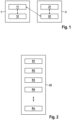
- Figure 1 shows a schematic block diagram of a device 1 for determining a type of computing device 21 of a device 2 of a motor vehicle.
- the invention is described in more detail below for an electromechanical brake booster as device 2 of the motor vehicle.
- the invention is not limited thereto and is applicable to various, particularly electromechanical, components of the motor vehicle, such as control units.
- the computing device 21 controls functions of the electromechanical brake booster, such as the buildup of brake pressure or the control of autonomous driving functions.
- the computing device 21 can be or comprise an application-specific integrated circuit (ASIC).
- ASIC application-specific integrated circuit
- the device 1 can be an electronic control unit (ECU) of the motor vehicle.
- the device 1 can also be a special device that is coupled to the electromechanical brake booster 2 after installation to check its correct installation.
- the device 1 comprises an interface 11 for accessing a memory device 22 of the electromechanical brake booster 2.
- the memory device 22 can be separate from the computing device 21, but can also be part of the computing device 21.
- the device 1 further comprises a determination device 12, which determines the type of the computing device 21 based on the result of the access. If, for example, a specific register can be accessed that only exists for a specific type of computing device 21, the determination device 12 can determine that the type of computing device 21 is precisely this type of computing device 21.
- a specific register can be accessed sequentially until no more transmission errors occur and the type of computing device 21 can therefore be determined.
- the order of the registers to be accessed can be fixed.
- the determination device 12 can also determine the type of the computing device 21 by reading a further register which includes a device identifier.
- Access to the storage device 22 via the interface 11 can be direct. However, it can also be provided that access to the storage device 22 via the interface 11 is indirect. According to one embodiment, interface 11 can be connected to an interface of the computing device 22 and, via the interface, can control the computing device 22 to access a corresponding register in the memory device 22. This eliminates the need for direct access of the device 1 to the memory device 22.
- information about the type of computing device can be stored in the storage device 22 and/or in a storage device (not shown) of the device 1.
- the determination device 12 controls the computing device 21 in such a way that functions of the computing device 21 are adapted and/or modified based on the determined type of computing device 21.
- the computing device 21 can be configured for autonomous driving if the type of computing device 21 permits this.
- Figure 2 shows a schematic representation of the memory device 22 with registers R1 to Rn of the device 2 of the motor vehicle.
- Registers R2 to Rn can also be provided.
- a second register R2 can only be available for the specific type of computing device 21, while this register cannot be accessed for computing devices 21 of a different type, resulting in a transmission error or access error.
- Figure 3 shows a flowchart of a method for determining a type of computing device of a device of a motor vehicle, and in particular of a device 2 described above.
- a first process step S1 the device 2 is put into operation for the first time.
- a determination device 12 accesses at least one register R1 to Rn of a memory device 22 of the device 2 via an interface 11.
- the access may be a read access, for example, to read a device identifier of the device 2 from a register R1 to Rn of the memory device 22. Additionally or alternatively, the access may be a read access to at least one register R1 to Rn.
- Each type of computing device 21 may comprise a specific register that is not available for other computing devices 21 or that cannot be accessed.
- the type of computing device 21 is determined based on the result of the access.
- the type of computing device 21 can be determined based on the read device identifier. Additionally or alternatively, the type of computing device 21 can be determined based on the presence or absence of a transmission error during the read access to the at least one register R1 to Rn.
- the determined type of the computing device 21 is optionally stored in the memory device 22 of the device.
- At least one software function of the computing device 21 can optionally be adapted and/or changed based on the determined type of the computing device 21.
Landscapes
- Engineering & Computer Science (AREA)
- Transportation (AREA)
- Mechanical Engineering (AREA)
- Automation & Control Theory (AREA)
- Human Computer Interaction (AREA)
- Valves And Accessory Devices For Braking Systems (AREA)
- Braking Systems And Boosters (AREA)
- Regulating Braking Force (AREA)
- Control Of Electric Motors In General (AREA)
- Safety Devices In Control Systems (AREA)
Claims (9)
- Procédé de détermination d'un type d'un dispositif informatique (21) d'un appareil (2) d'un véhicule automobile, le dispositif informatique (21) étant conçu pour commander au moins partiellement au moins une fonction de l'appareil (2) ; comprenant les étapes suivantes :accès (S2) à au moins un registre (R1-Rn) d'un dispositif de stockage (22) de l'appareil (2) ; etdétermination (S3) du type du dispositif informatique (21) sur la base d'un résultat de l'accès ;caractérisé en ce que l'accès à l'au moins un registre (R1-Rn) comprend un accès en lecture à au moins un registre prédéfini (R1-Rn), et la détermination du type du dispositif informatique (21) s'effectue en utilisant la présence ou l'absence d'une erreur de transmission.
- Procédé selon la revendication 1, dans lequel l'appareil (2) est un servofrein électromécanique.
- Procédé selon la revendication 1 ou 2, dans lequel le dispositif informatique (21) est un circuit intégré spécifique d'application, ASIC.
- Procédé selon l'une quelconque des revendications précédentes, dans lequel l'accès à l'au moins un registre (R1-Rn) comprend un accès en lecture pour lire un identifiant d'appareil de l'appareil (2), et dans lequel la détermination du type du dispositif informatique (21) s'effectue en utilisant l'identifiant d'appareil.
- Procédé selon l'une quelconque des revendications précédentes, dans lequel chaque type de dispositif informatique (21) comprend un registre spécifique (R1-Rn), et dans lequel un type respectif est attribué au dispositif informatique (21) si aucune erreur de transmission n'est présente pour le registre spécifique (R1-Rn) attribué au type.
- Procédé selon l'une quelconque des revendications précédentes, dans lequel le type du dispositif informatique (21) déterminé est stocké (S4) dans un dispositif de stockage (22) de l'appareil (2).
- Procédé selon l'une quelconque des revendications précédentes, dans lequel des fonctions logicielles du dispositif informatique (21) sont adaptées et/ou modifiées (S5) en utilisant le type déterminé du dispositif informatique (21).
- Procédé selon l'une quelconque des revendications précédentes, dans lequel la détermination du type du dispositif informatique (21) de l'appareil (2) est effectuée lors de la première mise en service (S1) de l'appareil (2), et l'appareil (2) est initialisé sur la base du type déterminé du dispositif informatique (21).
- Dispositif (1) de détermination d'un type d'un dispositif informatique (21) d'un appareil (2), le dispositif informatique (21) étant conçu pour commander au moins partiellement au moins une fonction de l'appareil (2) ; comprenantune interface (11) qui est conçue pour accéder à au moins un registre (R1-Rn) d'un dispositif de stockage (22) de l'appareil (2) ; etun dispositif de détermination (12) qui est conçu pour déterminer le type du dispositif informatique (21) sur la base d'un résultat de l'accès ;caractérisé en ce que l'accès à l'au moins un registre (R1-Rn) comprend un accès en lecture à au moins un registre prédéfini (R1-Rn), et en ce que le dispositif de détermination (12) est conçu pour déterminer le type du dispositif informatique (21) en utilisant la présence ou l'absence d'une erreur de transmission.
Applications Claiming Priority (2)
| Application Number | Priority Date | Filing Date | Title |
|---|---|---|---|
| DE102020214599.7A DE102020214599A1 (de) | 2020-11-19 | 2020-11-19 | Verfahren und Vorrichtung zum Ermitteln eines Typs einer Recheneinrichtung eines Geräts |
| PCT/EP2021/081652 WO2022106345A1 (fr) | 2020-11-19 | 2021-11-15 | Procédé et dispositif pour déterminer un type de dispositif informatique d'un appareil |
Publications (2)
| Publication Number | Publication Date |
|---|---|
| EP4247675A1 EP4247675A1 (fr) | 2023-09-27 |
| EP4247675B1 true EP4247675B1 (fr) | 2025-06-25 |
Family
ID=78709469
Family Applications (1)
| Application Number | Title | Priority Date | Filing Date |
|---|---|---|---|
| EP21811032.8A Active EP4247675B1 (fr) | 2020-11-19 | 2021-11-15 | Procédé et dispositif pour déterminer un type de dispositif informatique d'un appareil |
Country Status (7)
| Country | Link |
|---|---|
| US (1) | US20240001946A1 (fr) |
| EP (1) | EP4247675B1 (fr) |
| JP (1) | JP7656037B2 (fr) |
| KR (1) | KR20230108300A (fr) |
| CN (1) | CN116670005A (fr) |
| DE (1) | DE102020214599A1 (fr) |
| WO (1) | WO2022106345A1 (fr) |
Family Cites Families (15)
| Publication number | Priority date | Publication date | Assignee | Title |
|---|---|---|---|---|
| JP2000142363A (ja) * | 1998-11-10 | 2000-05-23 | Nisshinbo Ind Inc | 電子制御装置 |
| WO2003086830A1 (fr) * | 2002-04-18 | 2003-10-23 | Continental Teves Ag & Co. Ohg | Procede et dispositif permettant de fournir des donnees de fonctionnement de composants fonctionnels d'un appareil de commande de freinage de vehicule automobile |
| US20070174502A1 (en) * | 2006-01-23 | 2007-07-26 | Cheng-Chieh Lin | Method and apparatus of identifying type of non-volatile memory |
| DE102007010763A1 (de) * | 2007-03-06 | 2008-09-11 | Zf Friedrichshafen Ag | Verfahren zur adaptiven Konfigurationserkennung |
| JP4549396B2 (ja) * | 2008-01-18 | 2010-09-22 | 日立オートモティブシステムズ株式会社 | 車両制御装置 |
| DE102009026966A1 (de) | 2008-12-18 | 2010-07-01 | Robert Bosch Gmbh | Betrieb eines Bremskraftverstärkers als Pedalsimulator |
| DE102012014800A1 (de) * | 2012-07-26 | 2014-05-15 | Knorr-Bremse Systeme für Nutzfahrzeuge GmbH | Schaltungsanordnung zur Erfassung einer Art eines Magnetventils |
| DE102012215343A1 (de) * | 2012-08-29 | 2014-05-28 | Continental Automotive Gmbh | Verfahren zum Durchführen einer Sicherheitsfunktion eines Fahrzeugs und System zum Durchführen des Verfahrens |
| US9110592B2 (en) * | 2013-02-04 | 2015-08-18 | Microsoft Technology Licensing, Llc | Dynamic allocation of heterogenous memory in a computing system |
| CN103198000A (zh) * | 2013-04-02 | 2013-07-10 | 浪潮电子信息产业股份有限公司 | 一种linux系统下的故障内存位置定位方法 |
| US10002044B2 (en) * | 2014-08-19 | 2018-06-19 | Samsung Electronics Co., Ltd. | Memory devices and modules |
| US9823875B2 (en) * | 2015-08-31 | 2017-11-21 | LinkedIn Coporation | Transparent hybrid data storage |
| CN107291457B (zh) * | 2017-06-08 | 2020-07-03 | 重庆长安新能源汽车科技有限公司 | 整车控制器软件的远程更新计算系统及方法 |
| US10712976B2 (en) * | 2017-10-02 | 2020-07-14 | Western Digital Technologies, Inc. | Storage protection unit |
| GB2591490B (en) * | 2020-01-30 | 2022-03-02 | Advanced Risc Mach Ltd | An apparatus and method for controlling access to a set of memory mapped control registers |
-
2020
- 2020-11-19 DE DE102020214599.7A patent/DE102020214599A1/de active Pending
-
2021
- 2021-11-15 US US18/251,600 patent/US20240001946A1/en active Pending
- 2021-11-15 CN CN202180077418.0A patent/CN116670005A/zh active Pending
- 2021-11-15 EP EP21811032.8A patent/EP4247675B1/fr active Active
- 2021-11-15 WO PCT/EP2021/081652 patent/WO2022106345A1/fr not_active Ceased
- 2021-11-15 JP JP2023527346A patent/JP7656037B2/ja active Active
- 2021-11-15 KR KR1020237019871A patent/KR20230108300A/ko active Pending
Also Published As
| Publication number | Publication date |
|---|---|
| JP2023549746A (ja) | 2023-11-29 |
| CN116670005A (zh) | 2023-08-29 |
| DE102020214599A1 (de) | 2022-05-19 |
| EP4247675A1 (fr) | 2023-09-27 |
| KR20230108300A (ko) | 2023-07-18 |
| US20240001946A1 (en) | 2024-01-04 |
| JP7656037B2 (ja) | 2025-04-02 |
| WO2022106345A1 (fr) | 2022-05-27 |
Similar Documents
| Publication | Publication Date | Title |
|---|---|---|
| DE102019200994A1 (de) | Ein datenkommunikationsverfahren für ein fahrzeug | |
| DE102017117297A1 (de) | Kontrollsystem für ein Kraftfahrzeug, Kraftfahrzeug, Verfahren zur Kontrolle eines Kraftfahrzeugs, Computerprogrammprodukt und computerlesbares Medium | |
| EP1588380B1 (fr) | Procede de reconnaissance et/ou de correction d'erreurs d'acces a la memoire et circuit electronique destine a effectuer le procede | |
| DE10142511B4 (de) | Fehlerbehandlung von Softwaremodulen | |
| WO2024100105A1 (fr) | Procédé et système pour augmenter la confiance d'un conducteur dans une fonction de conduite automatisée | |
| EP4247675B1 (fr) | Procédé et dispositif pour déterminer un type de dispositif informatique d'un appareil | |
| EP3797352B1 (fr) | Procédé d'échange d'un premier code de programme exécutable et d'un deuxième code de programme exécutable et unité de commande | |
| DE102020211902A1 (de) | Vorrichtung für ein automatisches Parkbremssystem | |
| EP1611490B1 (fr) | Procede pour eviter des acces incorrects a des actionneurs dans un systeme de regulation global electronique et multifonctionnel | |
| WO2024083635A1 (fr) | Procédé de commande d'un système de freinage d'un véhicule automobile, système de freinage et véhicule automobile | |
| EP3308192B1 (fr) | Procédé pour déterminer une position de montage d'une unité capteur, système de communication et véhicule à moteur | |
| DE102017212918A1 (de) | Verfahren zum Betreiben eines Steuergerätes und Vorrichtung mit zugehörigem Steuergerät | |
| DE102021207244A1 (de) | Steuervorrichtung für zumindest eine erste Komponente eines Systems und Ansteuervorrichtung für zumindest eine zweite Komponente des gleichen Systems zum Zusammenwirken mit der Steuervorrichtung | |
| DE102006053559B4 (de) | Inbetriebnahme eines Notbremssystems in einer Werkstatt | |
| DE102016219315B4 (de) | Verfahren und Vorrichtung zur Vermeidung einer ungewollten Beschleunigung eines Kraftfahrzeugs | |
| EP3813309B1 (fr) | Procédé et dispositif de réglage d'un comportement de fonctionnement d'au moins une unité fonctionnelle et système | |
| EP4311734B1 (fr) | Procédé de fonctionnement d'un système de freinage pour un véhicule automobile et système de freinage correspondant | |
| WO2009062808A1 (fr) | Procédé pour identifier différents protocoles de communication dans un appareil de commande | |
| DE102018222150A1 (de) | Verfahren zum Notbremsen eines zumindest teilautomatisiert geführten Kraftfahrzeugs | |
| DE102018206554B4 (de) | Autonomes Bremssystem für ein Fahrzeug und Verfahren zum Betreiben eines autonomen Bremssystems eines Fahrzeugs | |
| DE102017221968A1 (de) | Verfahren zum Betreiben einer Lenkvorrichtung und Lenkvorrichtung | |
| EP3257232B1 (fr) | Procédé pour exploiter un appareil de commande dans différents systèmes de transmission de données, appareil de commande et système de transmission de données pour réaliser un tel procédé | |
| DE102024209874A1 (de) | Steuervorrichtung für zumindest einen ersten radindividuellen motorisierten Aktor eines Fahrzeugs und Motorsteuervorrichtung für einen zweiten radindividuellen motorisierten Aktor eines Fahrzeugs | |
| EP1248965A1 (fr) | Procede pour eviter des dysfonctionnements dans un systeme de traitement de signaux et systeme de processeur | |
| DE19748181B4 (de) | Verfahren zum Prüfen einer Funktion oder Einrichtung eines Fahrzeugs |
Legal Events
| Date | Code | Title | Description |
|---|---|---|---|
| STAA | Information on the status of an ep patent application or granted ep patent |
Free format text: STATUS: UNKNOWN |
|
| STAA | Information on the status of an ep patent application or granted ep patent |
Free format text: STATUS: THE INTERNATIONAL PUBLICATION HAS BEEN MADE |
|
| PUAI | Public reference made under article 153(3) epc to a published international application that has entered the european phase |
Free format text: ORIGINAL CODE: 0009012 |
|
| STAA | Information on the status of an ep patent application or granted ep patent |
Free format text: STATUS: REQUEST FOR EXAMINATION WAS MADE |
|
| 17P | Request for examination filed |
Effective date: 20230619 |
|
| AK | Designated contracting states |
Kind code of ref document: A1 Designated state(s): AL AT BE BG CH CY CZ DE DK EE ES FI FR GB GR HR HU IE IS IT LI LT LU LV MC MK MT NL NO PL PT RO RS SE SI SK SM TR |
|
| DAV | Request for validation of the european patent (deleted) | ||
| DAX | Request for extension of the european patent (deleted) | ||
| GRAP | Despatch of communication of intention to grant a patent |
Free format text: ORIGINAL CODE: EPIDOSNIGR1 |
|
| STAA | Information on the status of an ep patent application or granted ep patent |
Free format text: STATUS: GRANT OF PATENT IS INTENDED |
|
| INTG | Intention to grant announced |
Effective date: 20250403 |
|
| GRAS | Grant fee paid |
Free format text: ORIGINAL CODE: EPIDOSNIGR3 |
|
| GRAA | (expected) grant |
Free format text: ORIGINAL CODE: 0009210 |
|
| STAA | Information on the status of an ep patent application or granted ep patent |
Free format text: STATUS: THE PATENT HAS BEEN GRANTED |
|
| AK | Designated contracting states |
Kind code of ref document: B1 Designated state(s): AL AT BE BG CH CY CZ DE DK EE ES FI FR GB GR HR HU IE IS IT LI LT LU LV MC MK MT NL NO PL PT RO RS SE SI SK SM TR |
|
| REG | Reference to a national code |
Ref country code: GB Ref legal event code: FG4D Free format text: NOT ENGLISH |
|
| REG | Reference to a national code |
Ref country code: CH Ref legal event code: EP |
|
| REG | Reference to a national code |
Ref country code: DE Ref legal event code: R096 Ref document number: 502021007870 Country of ref document: DE |
|
| REG | Reference to a national code |
Ref country code: CH Ref legal event code: EP |
|
| REG | Reference to a national code |
Ref country code: IE Ref legal event code: FG4D Free format text: LANGUAGE OF EP DOCUMENT: GERMAN |
|
| PG25 | Lapsed in a contracting state [announced via postgrant information from national office to epo] |
Ref country code: FI Free format text: LAPSE BECAUSE OF FAILURE TO SUBMIT A TRANSLATION OF THE DESCRIPTION OR TO PAY THE FEE WITHIN THE PRESCRIBED TIME-LIMIT Effective date: 20250625 |
|
| REG | Reference to a national code |
Ref country code: LT Ref legal event code: MG9D |
|
| PG25 | Lapsed in a contracting state [announced via postgrant information from national office to epo] |
Ref country code: NO Free format text: LAPSE BECAUSE OF FAILURE TO SUBMIT A TRANSLATION OF THE DESCRIPTION OR TO PAY THE FEE WITHIN THE PRESCRIBED TIME-LIMIT Effective date: 20250925 Ref country code: GR Free format text: LAPSE BECAUSE OF FAILURE TO SUBMIT A TRANSLATION OF THE DESCRIPTION OR TO PAY THE FEE WITHIN THE PRESCRIBED TIME-LIMIT Effective date: 20250926 |
|
| PG25 | Lapsed in a contracting state [announced via postgrant information from national office to epo] |
Ref country code: BG Free format text: LAPSE BECAUSE OF FAILURE TO SUBMIT A TRANSLATION OF THE DESCRIPTION OR TO PAY THE FEE WITHIN THE PRESCRIBED TIME-LIMIT Effective date: 20250625 |
|
| PG25 | Lapsed in a contracting state [announced via postgrant information from national office to epo] |
Ref country code: HR Free format text: LAPSE BECAUSE OF FAILURE TO SUBMIT A TRANSLATION OF THE DESCRIPTION OR TO PAY THE FEE WITHIN THE PRESCRIBED TIME-LIMIT Effective date: 20250625 |
|
| PG25 | Lapsed in a contracting state [announced via postgrant information from national office to epo] |
Ref country code: RS Free format text: LAPSE BECAUSE OF FAILURE TO SUBMIT A TRANSLATION OF THE DESCRIPTION OR TO PAY THE FEE WITHIN THE PRESCRIBED TIME-LIMIT Effective date: 20250925 |
|
| PG25 | Lapsed in a contracting state [announced via postgrant information from national office to epo] |
Ref country code: LV Free format text: LAPSE BECAUSE OF FAILURE TO SUBMIT A TRANSLATION OF THE DESCRIPTION OR TO PAY THE FEE WITHIN THE PRESCRIBED TIME-LIMIT Effective date: 20250625 |
|
| REG | Reference to a national code |
Ref country code: NL Ref legal event code: MP Effective date: 20250625 |
|
| PG25 | Lapsed in a contracting state [announced via postgrant information from national office to epo] |
Ref country code: NL Free format text: LAPSE BECAUSE OF FAILURE TO SUBMIT A TRANSLATION OF THE DESCRIPTION OR TO PAY THE FEE WITHIN THE PRESCRIBED TIME-LIMIT Effective date: 20250625 |
|
| PG25 | Lapsed in a contracting state [announced via postgrant information from national office to epo] |
Ref country code: PT Free format text: LAPSE BECAUSE OF FAILURE TO SUBMIT A TRANSLATION OF THE DESCRIPTION OR TO PAY THE FEE WITHIN THE PRESCRIBED TIME-LIMIT Effective date: 20251027 |
|
| PG25 | Lapsed in a contracting state [announced via postgrant information from national office to epo] |
Ref country code: IS Free format text: LAPSE BECAUSE OF FAILURE TO SUBMIT A TRANSLATION OF THE DESCRIPTION OR TO PAY THE FEE WITHIN THE PRESCRIBED TIME-LIMIT Effective date: 20251025 |
|
| PGFP | Annual fee paid to national office [announced via postgrant information from national office to epo] |
Ref country code: GB Payment date: 20251120 Year of fee payment: 5 |
|
| PG25 | Lapsed in a contracting state [announced via postgrant information from national office to epo] |
Ref country code: SM Free format text: LAPSE BECAUSE OF FAILURE TO SUBMIT A TRANSLATION OF THE DESCRIPTION OR TO PAY THE FEE WITHIN THE PRESCRIBED TIME-LIMIT Effective date: 20250625 |
|
| PGFP | Annual fee paid to national office [announced via postgrant information from national office to epo] |
Ref country code: AT Payment date: 20260113 Year of fee payment: 5 |
|
| PGFP | Annual fee paid to national office [announced via postgrant information from national office to epo] |
Ref country code: FR Payment date: 20251125 Year of fee payment: 5 |
|
| PG25 | Lapsed in a contracting state [announced via postgrant information from national office to epo] |
Ref country code: CZ Free format text: LAPSE BECAUSE OF FAILURE TO SUBMIT A TRANSLATION OF THE DESCRIPTION OR TO PAY THE FEE WITHIN THE PRESCRIBED TIME-LIMIT Effective date: 20250625 |
|
| PG25 | Lapsed in a contracting state [announced via postgrant information from national office to epo] |
Ref country code: PL Free format text: LAPSE BECAUSE OF FAILURE TO SUBMIT A TRANSLATION OF THE DESCRIPTION OR TO PAY THE FEE WITHIN THE PRESCRIBED TIME-LIMIT Effective date: 20250625 |
|
| PG25 | Lapsed in a contracting state [announced via postgrant information from national office to epo] |
Ref country code: EE Free format text: LAPSE BECAUSE OF FAILURE TO SUBMIT A TRANSLATION OF THE DESCRIPTION OR TO PAY THE FEE WITHIN THE PRESCRIBED TIME-LIMIT Effective date: 20250625 |
|
| PG25 | Lapsed in a contracting state [announced via postgrant information from national office to epo] |
Ref country code: SK Free format text: LAPSE BECAUSE OF FAILURE TO SUBMIT A TRANSLATION OF THE DESCRIPTION OR TO PAY THE FEE WITHIN THE PRESCRIBED TIME-LIMIT Effective date: 20250625 |
|
| PG25 | Lapsed in a contracting state [announced via postgrant information from national office to epo] |
Ref country code: ES Free format text: LAPSE BECAUSE OF FAILURE TO SUBMIT A TRANSLATION OF THE DESCRIPTION OR TO PAY THE FEE WITHIN THE PRESCRIBED TIME-LIMIT Effective date: 20250625 |
|
| PG25 | Lapsed in a contracting state [announced via postgrant information from national office to epo] |
Ref country code: RO Free format text: LAPSE BECAUSE OF FAILURE TO SUBMIT A TRANSLATION OF THE DESCRIPTION OR TO PAY THE FEE WITHIN THE PRESCRIBED TIME-LIMIT Effective date: 20250625 |
|
| PG25 | Lapsed in a contracting state [announced via postgrant information from national office to epo] |
Ref country code: DK Free format text: LAPSE BECAUSE OF FAILURE TO SUBMIT A TRANSLATION OF THE DESCRIPTION OR TO PAY THE FEE WITHIN THE PRESCRIBED TIME-LIMIT Effective date: 20250625 |
|
| PGFP | Annual fee paid to national office [announced via postgrant information from national office to epo] |
Ref country code: DE Payment date: 20260126 Year of fee payment: 5 |
|
| PG25 | Lapsed in a contracting state [announced via postgrant information from national office to epo] |
Ref country code: IT Free format text: LAPSE BECAUSE OF FAILURE TO SUBMIT A TRANSLATION OF THE DESCRIPTION OR TO PAY THE FEE WITHIN THE PRESCRIBED TIME-LIMIT Effective date: 20250625 |
|
| PLBE | No opposition filed within time limit |
Free format text: ORIGINAL CODE: 0009261 |
|
| STAA | Information on the status of an ep patent application or granted ep patent |
Free format text: STATUS: NO OPPOSITION FILED WITHIN TIME LIMIT |