EP4247695B1 - Prädiktive energie- und bewegungsverwaltung für schwerlastfahrzeuge mit mehreren aufliegern - Google Patents
Prädiktive energie- und bewegungsverwaltung für schwerlastfahrzeuge mit mehreren aufliegern Download PDFInfo
- Publication number
- EP4247695B1 EP4247695B1 EP20811984.2A EP20811984A EP4247695B1 EP 4247695 B1 EP4247695 B1 EP 4247695B1 EP 20811984 A EP20811984 A EP 20811984A EP 4247695 B1 EP4247695 B1 EP 4247695B1
- Authority
- EP
- European Patent Office
- Prior art keywords
- vehicle
- heavy
- nocp
- path
- wheel
- Prior art date
- Legal status (The legal status is an assumption and is not a legal conclusion. Google has not performed a legal analysis and makes no representation as to the accuracy of the status listed.)
- Active
Links
Images




Classifications
-
- B—PERFORMING OPERATIONS; TRANSPORTING
- B60—VEHICLES IN GENERAL
- B60W—CONJOINT CONTROL OF VEHICLE SUB-UNITS OF DIFFERENT TYPE OR DIFFERENT FUNCTION; CONTROL SYSTEMS SPECIALLY ADAPTED FOR HYBRID VEHICLES; ROAD VEHICLE DRIVE CONTROL SYSTEMS FOR PURPOSES NOT RELATED TO THE CONTROL OF A PARTICULAR SUB-UNIT
- B60W30/00—Purposes of road vehicle drive control systems not related to the control of a particular sub-unit, e.g. of systems using conjoint control of vehicle sub-units
- B60W30/18—Propelling the vehicle
- B60W30/18172—Preventing, or responsive to skidding of wheels
-
- B—PERFORMING OPERATIONS; TRANSPORTING
- B60—VEHICLES IN GENERAL
- B60T—VEHICLE BRAKE CONTROL SYSTEMS OR PARTS THEREOF; BRAKE CONTROL SYSTEMS OR PARTS THEREOF, IN GENERAL; ARRANGEMENT OF BRAKING ELEMENTS ON VEHICLES IN GENERAL; PORTABLE DEVICES FOR PREVENTING UNWANTED MOVEMENT OF VEHICLES; VEHICLE MODIFICATIONS TO FACILITATE COOLING OF BRAKES
- B60T1/00—Arrangements of braking elements, i.e. of those parts where braking effect occurs specially for vehicles
- B60T1/02—Arrangements of braking elements, i.e. of those parts where braking effect occurs specially for vehicles acting by retarding wheels
- B60T1/10—Arrangements of braking elements, i.e. of those parts where braking effect occurs specially for vehicles acting by retarding wheels by utilising wheel movement for accumulating energy, e.g. driving air compressors
-
- B—PERFORMING OPERATIONS; TRANSPORTING
- B60—VEHICLES IN GENERAL
- B60T—VEHICLE BRAKE CONTROL SYSTEMS OR PARTS THEREOF; BRAKE CONTROL SYSTEMS OR PARTS THEREOF, IN GENERAL; ARRANGEMENT OF BRAKING ELEMENTS ON VEHICLES IN GENERAL; PORTABLE DEVICES FOR PREVENTING UNWANTED MOVEMENT OF VEHICLES; VEHICLE MODIFICATIONS TO FACILITATE COOLING OF BRAKES
- B60T7/00—Brake-action initiating means
- B60T7/12—Brake-action initiating means for automatic initiation; for initiation not subject to will of driver or passenger
- B60T7/16—Brake-action initiating means for automatic initiation; for initiation not subject to will of driver or passenger operated by remote control, i.e. initiating means not mounted on vehicle
- B60T7/18—Brake-action initiating means for automatic initiation; for initiation not subject to will of driver or passenger operated by remote control, i.e. initiating means not mounted on vehicle operated by wayside apparatus
-
- B—PERFORMING OPERATIONS; TRANSPORTING
- B60—VEHICLES IN GENERAL
- B60T—VEHICLE BRAKE CONTROL SYSTEMS OR PARTS THEREOF; BRAKE CONTROL SYSTEMS OR PARTS THEREOF, IN GENERAL; ARRANGEMENT OF BRAKING ELEMENTS ON VEHICLES IN GENERAL; PORTABLE DEVICES FOR PREVENTING UNWANTED MOVEMENT OF VEHICLES; VEHICLE MODIFICATIONS TO FACILITATE COOLING OF BRAKES
- B60T7/00—Brake-action initiating means
- B60T7/12—Brake-action initiating means for automatic initiation; for initiation not subject to will of driver or passenger
- B60T7/20—Brake-action initiating means for automatic initiation; for initiation not subject to will of driver or passenger specially for trailers, e.g. in case of uncoupling of or overrunning by trailer
-
- B—PERFORMING OPERATIONS; TRANSPORTING
- B60—VEHICLES IN GENERAL
- B60T—VEHICLE BRAKE CONTROL SYSTEMS OR PARTS THEREOF; BRAKE CONTROL SYSTEMS OR PARTS THEREOF, IN GENERAL; ARRANGEMENT OF BRAKING ELEMENTS ON VEHICLES IN GENERAL; PORTABLE DEVICES FOR PREVENTING UNWANTED MOVEMENT OF VEHICLES; VEHICLE MODIFICATIONS TO FACILITATE COOLING OF BRAKES
- B60T7/00—Brake-action initiating means
- B60T7/12—Brake-action initiating means for automatic initiation; for initiation not subject to will of driver or passenger
- B60T7/22—Brake-action initiating means for automatic initiation; for initiation not subject to will of driver or passenger initiated by contact of vehicle, e.g. bumper, with an external object, e.g. another vehicle, or by means of contactless obstacle detectors mounted on the vehicle
-
- B—PERFORMING OPERATIONS; TRANSPORTING
- B60—VEHICLES IN GENERAL
- B60T—VEHICLE BRAKE CONTROL SYSTEMS OR PARTS THEREOF; BRAKE CONTROL SYSTEMS OR PARTS THEREOF, IN GENERAL; ARRANGEMENT OF BRAKING ELEMENTS ON VEHICLES IN GENERAL; PORTABLE DEVICES FOR PREVENTING UNWANTED MOVEMENT OF VEHICLES; VEHICLE MODIFICATIONS TO FACILITATE COOLING OF BRAKES
- B60T8/00—Arrangements for adjusting wheel-braking force to meet varying vehicular or ground-surface conditions, e.g. limiting or varying distribution of braking force
- B60T8/17—Using electrical or electronic regulation means to control braking
- B60T8/1701—Braking or traction control means specially adapted for particular types of vehicles
- B60T8/1708—Braking or traction control means specially adapted for particular types of vehicles for lorries or tractor-trailer combinations
-
- B—PERFORMING OPERATIONS; TRANSPORTING
- B60—VEHICLES IN GENERAL
- B60W—CONJOINT CONTROL OF VEHICLE SUB-UNITS OF DIFFERENT TYPE OR DIFFERENT FUNCTION; CONTROL SYSTEMS SPECIALLY ADAPTED FOR HYBRID VEHICLES; ROAD VEHICLE DRIVE CONTROL SYSTEMS FOR PURPOSES NOT RELATED TO THE CONTROL OF A PARTICULAR SUB-UNIT
- B60W20/00—Control systems specially adapted for hybrid vehicles
- B60W20/10—Controlling the power contribution of each of the prime movers to meet required power demand
- B60W20/12—Controlling the power contribution of each of the prime movers to meet required power demand using control strategies taking into account route information
-
- B—PERFORMING OPERATIONS; TRANSPORTING
- B60—VEHICLES IN GENERAL
- B60W—CONJOINT CONTROL OF VEHICLE SUB-UNITS OF DIFFERENT TYPE OR DIFFERENT FUNCTION; CONTROL SYSTEMS SPECIALLY ADAPTED FOR HYBRID VEHICLES; ROAD VEHICLE DRIVE CONTROL SYSTEMS FOR PURPOSES NOT RELATED TO THE CONTROL OF A PARTICULAR SUB-UNIT
- B60W30/00—Purposes of road vehicle drive control systems not related to the control of a particular sub-unit, e.g. of systems using conjoint control of vehicle sub-units
- B60W30/02—Control of vehicle driving stability
-
- B—PERFORMING OPERATIONS; TRANSPORTING
- B60—VEHICLES IN GENERAL
- B60W—CONJOINT CONTROL OF VEHICLE SUB-UNITS OF DIFFERENT TYPE OR DIFFERENT FUNCTION; CONTROL SYSTEMS SPECIALLY ADAPTED FOR HYBRID VEHICLES; ROAD VEHICLE DRIVE CONTROL SYSTEMS FOR PURPOSES NOT RELATED TO THE CONTROL OF A PARTICULAR SUB-UNIT
- B60W30/00—Purposes of road vehicle drive control systems not related to the control of a particular sub-unit, e.g. of systems using conjoint control of vehicle sub-units
- B60W30/18—Propelling the vehicle
- B60W30/18009—Propelling the vehicle related to particular drive situations
- B60W30/18109—Braking
- B60W30/18127—Regenerative braking
-
- B—PERFORMING OPERATIONS; TRANSPORTING
- B60—VEHICLES IN GENERAL
- B60W—CONJOINT CONTROL OF VEHICLE SUB-UNITS OF DIFFERENT TYPE OR DIFFERENT FUNCTION; CONTROL SYSTEMS SPECIALLY ADAPTED FOR HYBRID VEHICLES; ROAD VEHICLE DRIVE CONTROL SYSTEMS FOR PURPOSES NOT RELATED TO THE CONTROL OF A PARTICULAR SUB-UNIT
- B60W30/00—Purposes of road vehicle drive control systems not related to the control of a particular sub-unit, e.g. of systems using conjoint control of vehicle sub-units
- B60W30/18—Propelling the vehicle
- B60W30/18009—Propelling the vehicle related to particular drive situations
- B60W30/18145—Cornering
-
- B—PERFORMING OPERATIONS; TRANSPORTING
- B62—LAND VEHICLES FOR TRAVELLING OTHERWISE THAN ON RAILS
- B62D—MOTOR VEHICLES; TRAILERS
- B62D53/00—Tractor-trailer combinations; Road trains
- B62D53/04—Tractor-trailer combinations; Road trains comprising a vehicle carrying an essential part of the other vehicle's load by having supporting means for the front or rear part of the other vehicle
- B62D53/06—Semi-trailers
-
- B—PERFORMING OPERATIONS; TRANSPORTING
- B62—LAND VEHICLES FOR TRAVELLING OTHERWISE THAN ON RAILS
- B62D—MOTOR VEHICLES; TRAILERS
- B62D53/00—Tractor-trailer combinations; Road trains
- B62D53/04—Tractor-trailer combinations; Road trains comprising a vehicle carrying an essential part of the other vehicle's load by having supporting means for the front or rear part of the other vehicle
- B62D53/08—Fifth wheel traction couplings
- B62D53/0857—Auxiliary semi-trailer handling or loading equipment, e.g. ramps, rigs, coupling supports
- B62D53/0864—Dollies for fifth wheel coupling
-
- B—PERFORMING OPERATIONS; TRANSPORTING
- B62—LAND VEHICLES FOR TRAVELLING OTHERWISE THAN ON RAILS
- B62D—MOTOR VEHICLES; TRAILERS
- B62D59/00—Trailers with driven ground wheels or the like
- B62D59/04—Trailers with driven ground wheels or the like driven from propulsion unit on trailer
-
- F—MECHANICAL ENGINEERING; LIGHTING; HEATING; WEAPONS; BLASTING
- F16—ENGINEERING ELEMENTS AND UNITS; GENERAL MEASURES FOR PRODUCING AND MAINTAINING EFFECTIVE FUNCTIONING OF MACHINES OR INSTALLATIONS; THERMAL INSULATION IN GENERAL
- F16D—COUPLINGS FOR TRANSMITTING ROTATION; CLUTCHES; BRAKES
- F16D61/00—Brakes with means for making the energy absorbed available for use
-
- B—PERFORMING OPERATIONS; TRANSPORTING
- B60—VEHICLES IN GENERAL
- B60T—VEHICLE BRAKE CONTROL SYSTEMS OR PARTS THEREOF; BRAKE CONTROL SYSTEMS OR PARTS THEREOF, IN GENERAL; ARRANGEMENT OF BRAKING ELEMENTS ON VEHICLES IN GENERAL; PORTABLE DEVICES FOR PREVENTING UNWANTED MOVEMENT OF VEHICLES; VEHICLE MODIFICATIONS TO FACILITATE COOLING OF BRAKES
- B60T2201/00—Particular use of vehicle brake systems; Special systems using also the brakes; Special software modules within the brake system controller
- B60T2201/16—Curve braking control, e.g. turn control within ABS control algorithm
-
- B—PERFORMING OPERATIONS; TRANSPORTING
- B60—VEHICLES IN GENERAL
- B60T—VEHICLE BRAKE CONTROL SYSTEMS OR PARTS THEREOF; BRAKE CONTROL SYSTEMS OR PARTS THEREOF, IN GENERAL; ARRANGEMENT OF BRAKING ELEMENTS ON VEHICLES IN GENERAL; PORTABLE DEVICES FOR PREVENTING UNWANTED MOVEMENT OF VEHICLES; VEHICLE MODIFICATIONS TO FACILITATE COOLING OF BRAKES
- B60T2210/00—Detection or estimation of road or environment conditions; Detection or estimation of road shapes
- B60T2210/20—Road shapes
-
- B—PERFORMING OPERATIONS; TRANSPORTING
- B60—VEHICLES IN GENERAL
- B60T—VEHICLE BRAKE CONTROL SYSTEMS OR PARTS THEREOF; BRAKE CONTROL SYSTEMS OR PARTS THEREOF, IN GENERAL; ARRANGEMENT OF BRAKING ELEMENTS ON VEHICLES IN GENERAL; PORTABLE DEVICES FOR PREVENTING UNWANTED MOVEMENT OF VEHICLES; VEHICLE MODIFICATIONS TO FACILITATE COOLING OF BRAKES
- B60T2270/00—Further aspects of brake control systems not otherwise provided for
- B60T2270/86—Optimizing braking by using ESP vehicle or tyre model
-
- B—PERFORMING OPERATIONS; TRANSPORTING
- B60—VEHICLES IN GENERAL
- B60W—CONJOINT CONTROL OF VEHICLE SUB-UNITS OF DIFFERENT TYPE OR DIFFERENT FUNCTION; CONTROL SYSTEMS SPECIALLY ADAPTED FOR HYBRID VEHICLES; ROAD VEHICLE DRIVE CONTROL SYSTEMS FOR PURPOSES NOT RELATED TO THE CONTROL OF A PARTICULAR SUB-UNIT
- B60W50/00—Details of control systems for road vehicle drive control not related to the control of a particular sub-unit, e.g. process diagnostic or vehicle driver interfaces
- B60W2050/0001—Details of the control system
- B60W2050/0002—Automatic control, details of type of controller or control system architecture
- B60W2050/0013—Optimal controllers
-
- B—PERFORMING OPERATIONS; TRANSPORTING
- B60—VEHICLES IN GENERAL
- B60W—CONJOINT CONTROL OF VEHICLE SUB-UNITS OF DIFFERENT TYPE OR DIFFERENT FUNCTION; CONTROL SYSTEMS SPECIALLY ADAPTED FOR HYBRID VEHICLES; ROAD VEHICLE DRIVE CONTROL SYSTEMS FOR PURPOSES NOT RELATED TO THE CONTROL OF A PARTICULAR SUB-UNIT
- B60W2300/00—Indexing codes relating to the type of vehicle
- B60W2300/14—Tractor-trailers, i.e. combinations of a towing vehicle and one or more towed vehicles, e.g. caravans; Road trains
-
- B—PERFORMING OPERATIONS; TRANSPORTING
- B60—VEHICLES IN GENERAL
- B60W—CONJOINT CONTROL OF VEHICLE SUB-UNITS OF DIFFERENT TYPE OR DIFFERENT FUNCTION; CONTROL SYSTEMS SPECIALLY ADAPTED FOR HYBRID VEHICLES; ROAD VEHICLE DRIVE CONTROL SYSTEMS FOR PURPOSES NOT RELATED TO THE CONTROL OF A PARTICULAR SUB-UNIT
- B60W2300/00—Indexing codes relating to the type of vehicle
- B60W2300/14—Tractor-trailers, i.e. combinations of a towing vehicle and one or more towed vehicles, e.g. caravans; Road trains
- B60W2300/145—Semi-trailers
-
- B—PERFORMING OPERATIONS; TRANSPORTING
- B60—VEHICLES IN GENERAL
- B60W—CONJOINT CONTROL OF VEHICLE SUB-UNITS OF DIFFERENT TYPE OR DIFFERENT FUNCTION; CONTROL SYSTEMS SPECIALLY ADAPTED FOR HYBRID VEHICLES; ROAD VEHICLE DRIVE CONTROL SYSTEMS FOR PURPOSES NOT RELATED TO THE CONTROL OF A PARTICULAR SUB-UNIT
- B60W2300/00—Indexing codes relating to the type of vehicle
- B60W2300/14—Tractor-trailers, i.e. combinations of a towing vehicle and one or more towed vehicles, e.g. caravans; Road trains
- B60W2300/147—Road trains
-
- B—PERFORMING OPERATIONS; TRANSPORTING
- B60—VEHICLES IN GENERAL
- B60W—CONJOINT CONTROL OF VEHICLE SUB-UNITS OF DIFFERENT TYPE OR DIFFERENT FUNCTION; CONTROL SYSTEMS SPECIALLY ADAPTED FOR HYBRID VEHICLES; ROAD VEHICLE DRIVE CONTROL SYSTEMS FOR PURPOSES NOT RELATED TO THE CONTROL OF A PARTICULAR SUB-UNIT
- B60W2300/00—Indexing codes relating to the type of vehicle
- B60W2300/18—Four-wheel drive vehicles
-
- B—PERFORMING OPERATIONS; TRANSPORTING
- B60—VEHICLES IN GENERAL
- B60W—CONJOINT CONTROL OF VEHICLE SUB-UNITS OF DIFFERENT TYPE OR DIFFERENT FUNCTION; CONTROL SYSTEMS SPECIALLY ADAPTED FOR HYBRID VEHICLES; ROAD VEHICLE DRIVE CONTROL SYSTEMS FOR PURPOSES NOT RELATED TO THE CONTROL OF A PARTICULAR SUB-UNIT
- B60W2520/00—Input parameters relating to overall vehicle dynamics
- B60W2520/10—Longitudinal speed
-
- B—PERFORMING OPERATIONS; TRANSPORTING
- B60—VEHICLES IN GENERAL
- B60W—CONJOINT CONTROL OF VEHICLE SUB-UNITS OF DIFFERENT TYPE OR DIFFERENT FUNCTION; CONTROL SYSTEMS SPECIALLY ADAPTED FOR HYBRID VEHICLES; ROAD VEHICLE DRIVE CONTROL SYSTEMS FOR PURPOSES NOT RELATED TO THE CONTROL OF A PARTICULAR SUB-UNIT
- B60W2520/00—Input parameters relating to overall vehicle dynamics
- B60W2520/10—Longitudinal speed
- B60W2520/105—Longitudinal acceleration
-
- B—PERFORMING OPERATIONS; TRANSPORTING
- B60—VEHICLES IN GENERAL
- B60W—CONJOINT CONTROL OF VEHICLE SUB-UNITS OF DIFFERENT TYPE OR DIFFERENT FUNCTION; CONTROL SYSTEMS SPECIALLY ADAPTED FOR HYBRID VEHICLES; ROAD VEHICLE DRIVE CONTROL SYSTEMS FOR PURPOSES NOT RELATED TO THE CONTROL OF A PARTICULAR SUB-UNIT
- B60W2520/00—Input parameters relating to overall vehicle dynamics
- B60W2520/26—Wheel slip
-
- B—PERFORMING OPERATIONS; TRANSPORTING
- B60—VEHICLES IN GENERAL
- B60W—CONJOINT CONTROL OF VEHICLE SUB-UNITS OF DIFFERENT TYPE OR DIFFERENT FUNCTION; CONTROL SYSTEMS SPECIALLY ADAPTED FOR HYBRID VEHICLES; ROAD VEHICLE DRIVE CONTROL SYSTEMS FOR PURPOSES NOT RELATED TO THE CONTROL OF A PARTICULAR SUB-UNIT
- B60W2552/00—Input parameters relating to infrastructure
- B60W2552/15—Road slope, i.e. the inclination of a road segment in the longitudinal direction
-
- B—PERFORMING OPERATIONS; TRANSPORTING
- B60—VEHICLES IN GENERAL
- B60W—CONJOINT CONTROL OF VEHICLE SUB-UNITS OF DIFFERENT TYPE OR DIFFERENT FUNCTION; CONTROL SYSTEMS SPECIALLY ADAPTED FOR HYBRID VEHICLES; ROAD VEHICLE DRIVE CONTROL SYSTEMS FOR PURPOSES NOT RELATED TO THE CONTROL OF A PARTICULAR SUB-UNIT
- B60W2552/00—Input parameters relating to infrastructure
- B60W2552/20—Road profile, i.e. the change in elevation or curvature of a plurality of continuous road segments
-
- B—PERFORMING OPERATIONS; TRANSPORTING
- B60—VEHICLES IN GENERAL
- B60W—CONJOINT CONTROL OF VEHICLE SUB-UNITS OF DIFFERENT TYPE OR DIFFERENT FUNCTION; CONTROL SYSTEMS SPECIALLY ADAPTED FOR HYBRID VEHICLES; ROAD VEHICLE DRIVE CONTROL SYSTEMS FOR PURPOSES NOT RELATED TO THE CONTROL OF A PARTICULAR SUB-UNIT
- B60W2552/00—Input parameters relating to infrastructure
- B60W2552/30—Road curve radius
-
- B—PERFORMING OPERATIONS; TRANSPORTING
- B60—VEHICLES IN GENERAL
- B60W—CONJOINT CONTROL OF VEHICLE SUB-UNITS OF DIFFERENT TYPE OR DIFFERENT FUNCTION; CONTROL SYSTEMS SPECIALLY ADAPTED FOR HYBRID VEHICLES; ROAD VEHICLE DRIVE CONTROL SYSTEMS FOR PURPOSES NOT RELATED TO THE CONTROL OF A PARTICULAR SUB-UNIT
- B60W2552/00—Input parameters relating to infrastructure
- B60W2552/40—Coefficient of friction
-
- B—PERFORMING OPERATIONS; TRANSPORTING
- B60—VEHICLES IN GENERAL
- B60W—CONJOINT CONTROL OF VEHICLE SUB-UNITS OF DIFFERENT TYPE OR DIFFERENT FUNCTION; CONTROL SYSTEMS SPECIALLY ADAPTED FOR HYBRID VEHICLES; ROAD VEHICLE DRIVE CONTROL SYSTEMS FOR PURPOSES NOT RELATED TO THE CONTROL OF A PARTICULAR SUB-UNIT
- B60W2720/00—Output or target parameters relating to overall vehicle dynamics
- B60W2720/10—Longitudinal speed
- B60W2720/103—Speed profile
-
- B—PERFORMING OPERATIONS; TRANSPORTING
- B60—VEHICLES IN GENERAL
- B60W—CONJOINT CONTROL OF VEHICLE SUB-UNITS OF DIFFERENT TYPE OR DIFFERENT FUNCTION; CONTROL SYSTEMS SPECIALLY ADAPTED FOR HYBRID VEHICLES; ROAD VEHICLE DRIVE CONTROL SYSTEMS FOR PURPOSES NOT RELATED TO THE CONTROL OF A PARTICULAR SUB-UNIT
- B60W2720/00—Output or target parameters relating to overall vehicle dynamics
- B60W2720/10—Longitudinal speed
- B60W2720/106—Longitudinal acceleration
-
- B—PERFORMING OPERATIONS; TRANSPORTING
- B60—VEHICLES IN GENERAL
- B60W—CONJOINT CONTROL OF VEHICLE SUB-UNITS OF DIFFERENT TYPE OR DIFFERENT FUNCTION; CONTROL SYSTEMS SPECIALLY ADAPTED FOR HYBRID VEHICLES; ROAD VEHICLE DRIVE CONTROL SYSTEMS FOR PURPOSES NOT RELATED TO THE CONTROL OF A PARTICULAR SUB-UNIT
- B60W2720/00—Output or target parameters relating to overall vehicle dynamics
- B60W2720/12—Lateral speed
- B60W2720/125—Lateral acceleration
-
- B—PERFORMING OPERATIONS; TRANSPORTING
- B60—VEHICLES IN GENERAL
- B60W—CONJOINT CONTROL OF VEHICLE SUB-UNITS OF DIFFERENT TYPE OR DIFFERENT FUNCTION; CONTROL SYSTEMS SPECIALLY ADAPTED FOR HYBRID VEHICLES; ROAD VEHICLE DRIVE CONTROL SYSTEMS FOR PURPOSES NOT RELATED TO THE CONTROL OF A PARTICULAR SUB-UNIT
- B60W2720/00—Output or target parameters relating to overall vehicle dynamics
- B60W2720/26—Wheel slip
-
- B—PERFORMING OPERATIONS; TRANSPORTING
- B60—VEHICLES IN GENERAL
- B60Y—INDEXING SCHEME RELATING TO ASPECTS CROSS-CUTTING VEHICLE TECHNOLOGY
- B60Y2200/00—Type of vehicle
- B60Y2200/10—Road Vehicles
- B60Y2200/14—Trucks; Load vehicles, Busses
- B60Y2200/142—Heavy duty trucks
-
- B—PERFORMING OPERATIONS; TRANSPORTING
- B60—VEHICLES IN GENERAL
- B60Y—INDEXING SCHEME RELATING TO ASPECTS CROSS-CUTTING VEHICLE TECHNOLOGY
- B60Y2200/00—Type of vehicle
- B60Y2200/10—Road Vehicles
- B60Y2200/14—Trucks; Load vehicles, Busses
- B60Y2200/142—Heavy duty trucks
- B60Y2200/1422—Multi-axle trucks
Definitions
- the present invention relates to heavy-duty vehicles for cargo transport, and in particular to multitrailer vehicles comprising one or more vehicle units.
- multitrailer vehicles comprising one or more vehicle units.
- the invention will be described mainly with respect to semi-trailer vehicles and trucks, the invention is not restricted to this particular type of vehicle but may also be used in other types of vehicles.
- a semitrailer vehicle normally comprises a tractor arranged to tow a trailer unit via a fifth wheel connection.
- a dolly vehicle unit can be added to the vehicle combination, which allows for additional trailer units to be towed by the same tractor.
- a traditional dolly is an unpowered vehicle unit designed for connection to a tractor unit, truck, or prime mover vehicle with strong traction power.
- Dolly vehicles comprising on-board energy sources such as electric machines and dolly vehicles with one or more steered axles have recently been proposed. Such dolly vehicles can provide additional power to the vehicle combination, thus reducing the traction power requirements imposed on the prime mover vehicle. Electrified dolly vehicles may also reduce overall fuel consumption by the vehicle combination, since they provide a degree of hybridization to conventional diesel-engine powered tractors. Steered axle dolly vehicles may furthermore be used for improved steering of the vehicle combination, e.g., when negotiating sharp curves.
- US 10,518,831 B2 relates to self-powered steerable dolly vehicles. Methods for controlling the dolly vehicles in order to, e.g., negotiate sharp turns, are disclosed. Methods for controlling propulsion and regenerative braking operations in dependence of an upcoming vehicle route to be travelled by the dolly vehicle are also discussed.
- Hierarchical Adaptive Path-Tracking Control for Autonomous Vehicles by Changfang et al., IEEE Transactions on Intelligent Transportation Systems, vol. 16, no. 5, 2015, p. 2900-2912 , discloses a hierarchical controller for an autonomous vehicle to track a reference path in the presence of uncertainties.
- US 2020/298878 A1 discloses a method for automatically driving a vehicle.
- the method comprises obtaining information related to an upcoming vehicle path and vehicle maneuver along the path, configuring lateral and longitudinal wheel slip limits for at least two wheels of an axle or lumped group-axle on the heavy-duty vehicle, wherein lateral and longitudinal wheel slip values are related to respective lateral and longitudinal tyre force values via a pre-determined combined tyre slip model, and determining a vehicle motion profile for performing the vehicle maneuver along the path as a solution to a non-linear optimal control problem (NOCP) in a predictive manner, wherein the NOCP is constrained by the lateral and longitudinal wheel slip limits.
- NOCP non-linear optimal control problem
- the method also comprises controlling the motion of the heavy-duty vehicle along the path based on the determined target vehicle motion profile.
- the vehicle looks ahead along a planned route and plans, e.g., optimal speed and tyre force allocation via control of the longitudinal and lateral tyre slips.
- the constraints on lateral and longitudinal wheel slip ensure that the vehicle travels safely along the planned path with an optimal speed, avoiding undesirable events such as excessive wheel slip, jack-knifing, etc.
- the method may also comprise obtaining information related to a road friction coefficient along the upcoming vehicle path, in which case the NOCP can be formulated to account for the road friction coefficient along the upcoming vehicle path.
- the vehicle motion profile comprises a target tyre force or torque trajectory and/or a target wheel slip trajectory for at least two wheels to be followed along the upcoming vehicle path.
- the vehicle motion profile may comprise a target vehicle unit acceleration and/or a target vehicle speed to be followed along the upcoming vehicle path.
- the heavy-duty vehicle comprises a propulsion actuator with regenerative braking capability on more than one driven axle, i.e., an electric machine.
- This electric machine may be a stand-alone propulsion unit or arranged in a hybrid drive arrangement together with a combustion engine or other propulsion device.
- the method comprises determining the vehicle motion profile for performing the vehicle maneuver along the path as a solution to an NOCP wherein the NOCP is configured to minimize an energy consumption by the vehicle along the path.
- this NOCP approach allows for optimal or at least near-optimal control of the vehicle, which is an advantage.
- the NOCP formulations considered herein also fit well into the proposed wheel-slip based control approach.
- a wide variety of different constraints can be added to the NOCP in order to obtain solutions meeting certain prerequisites and requirements.
- the method also comprises converting the NOCP to a sequential program and determining the vehicle motion profile as a solution to the sequential program.
- the sequential program allows for solving the NOCP in an approximate low complex manner, albeit still with adequate accuracy and performance.
- methods comprising model predictive control linear or nonlinear can be used with advantage.
- the methods discussed herein may comprise any of configuring a nonlinear single-track vehicle model of the heavy-duty vehicle with lumped group-axles, reducing a number of states in one or more longitudinal dynamic equations of the NOCP, configuring two different levels of discretization for longitudinal and lateral dynamic equations of the NOCP, preferably a first discretization with a long time horizon for the longitudinal dynamic equations of the NOCP and a second discretization for the lateral dynamic equations of the NOCP that are active for a shorter time horizon, wherein the first discretization is more coarse than the second discretization, and configuring a linear time-varying (LTV) version of the lateral dynamic equations of the NOCP and/or the combined tyre slip model, where the LTV is linearized around an initial reference vehicle motion profile along the path (p).
- LTV linear time-varying
- DAE differential-algebraic system of equations
- the method also comprises controlling the motion of the heavy-duty vehicle by issuing any of: an acceleration request, a wheel torque request, and/or a wheel slip request, in dependence of the vehicle motion profile to one or more actuator control units of the heavy-duty vehicle.
- FIG 1A illustrates an example vehicle combination 100a for cargo transport.
- the vehicle combination 100a comprises a truck or towing vehicle 110 configured to tow a first trailer unit 120 in a known manner, e.g., by a fifth wheel connection.
- a dolly vehicle 130 can be connected to the rear of the first trailer 120 via a drawbar 136. This dolly vehicle can then tow a second trailer 140, thus increasing the cargo transport capacity of the vehicle combination.
- a second dolly vehicle unit can be connected to the second trailer 140 in order to tow a third trailer unit (not shown in Figure 1A ).
- Such heavy-duty vehicles 100a are referred to as multitrailer vehicles.
- the towing vehicle is shown as comprising a front axle 111 and a lumped group-axle 115, while the second and first trailer units each comprise a lumped group-axle 125, 145.
- the dolly vehicle 130 is also shown comprising a lumped group-axle 135.
- a lumped group-axle is considered to be a group of at least two adjacent axles that can be effectively treated as a single axle, e.g. by a control unit comprised in the vehicle.
- a heavy-duty vehicle is taken to be a vehicle designed for the handling and transport of heavier objects or large quantities of cargo.
- a heavy-duty vehicle could be a semi-trailer vehicle or a truck.
- a heavy-duty vehicle could be a vehicle designed for use in construction or farming.
- a dolly vehicle 130 is traditionally a passive vehicle comprising no driven or steerable axles, and with a relatively short wheelbase. It has recently been shown that self-powered dolly vehicles may provide both increased fuel efficiency and maneuverability.
- This type of self-powered dolly vehicle comprises an on-board energy source, such as a battery, super-capacitor or a fuel cell stack, and at least one pair of driven wheels. Some self-powered dolly vehicles may also be steerable.
- An example of self-powered steerable axles of this type suitable for use with self-powered dolly vehicle will be discussed in more detail below in connection to, e.g., Figures 2A and 2B .
- These driven axles can of course also be used with prime movers 110 and trailer units 120, 140.
- Increased fuel efficiency is for instance obtained if an electric machine arranged for regenerative braking is installed in the dolly vehicle or self-powered trailer unit.
- the vehicle combination then effectively becomes a hybrid electric vehicle, even if the towing vehicle only comprises a traditional diesel engine with no on-board electric hybridization.
- Adding a self-powered dolly vehicle 130 to the vehicle combination 100a can also improve startability, since the dolly vehicle is then able to generate extra torque when bringing the vehicle combination into motion from a stand-still.
- Vehicle startability may be a limiting factor in the maximum load possible to carry, and a self-powered dolly vehicle may therefore contribute to an increased cargo capacity, which is an advantage.
- Both the truck 110 and the self-powered steerable dolly vehicle 130 may comprise electric machines for propulsion and/or regenerative brakes for decelerating the vehicle unit while harvesting energy.
- the self-powered vehicle units also comprise respective energy sources.
- An energy source is normally a battery, super-capacitor, fuel cell or other device arranged to store electrical energy.
- an energy source may also comprise mechanical energy storage devices such as springs and compressed air tanks for pneumatic machines. Combinations of different types of energy sources can also be used.
- a traditional fuel tank for storing gasoline or diesel fuel can of course also be considered an energy source in this context.
- the present invention however, focuses on propulsion arrangements based on electric machines powered by an electrical energy storage device, such as a battery or a fuel cell stack.
- truck and full trailer combinations 100b illustrated in Figure 1B , which may also comprise more than one trailer unit.
- These vehicles comprise a truck 150 arranged to tow a full trailer unit 160.
- the truck 150 is shown as comprising a front axle 151 and a lumped group-axle 155.
- a full trailer unit is a trailer which is able to fully support itself on the ground, i.e., it comprises both front 161 and rear 162 trailer axles.
- the front axle 161 can be self-powered and also steerable just like that of the dolly vehicle unit 130.
- most if not all of the techniques, devices and methods discussed herein are also applicable to heavy-duty vehicles like that shown in Figure 1B .
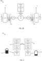
- FIGS 2A and 2B schematically illustrate example driven axle arrangements 200a, 200b which can be used with, e.g., the self-powered dolly vehicle unit 130 or the full trailer 160.
- the driven axle arrangements comprise an axle 201 with left- and right-hand side driven wheels 210I, 210r.
- the axle is powered by a propulsion arrangement.
- the example 200a shown in Figure 2A comprises a propulsion arrangement comprising an energy source 250 connected to two electrical machines 230I, 230r which each drive one of the left and right wheels 210I, 210r.
- the example driven axle arrangement 200b shown in Figure 2B comprises a propulsion arrangement also comprising an energy source 250, connected to a single electrical machine 230, which in turn powers the left and right wheels 210I, 210r via a differential 235.
- the wheel angular velocities ⁇ 1, ⁇ 2 and wheel speeds v1, v2 can thus differ between the left and right wheels.
- the example driven axle arrangements 200a, 200b may also comprise active an active suspension 215I, 215r, arranged to maintain a desirable height of the vehicle unit relative to the ground.
- the active suspension 215I, 215r may be controlled by a control unit 240 like the one shown in Figure 2A .
- the heavy-duty vehicles discussed herein may comprise a propulsion actuator with regenerative braking capability on more than one driven axle.
- Both the towing vehicle 110 and the steerable dolly vehicle 130 may comprise control units, which will be discussed in more detail below in connection to Figure 8 .
- These control units can be arranged according to a layered functional architecture where some functions may be comprised in a traffic situation management (TSM) layer and some other functions may be comprised in a vehicle motion management (VMM) layer.
- TSM traffic situation management
- VMM vehicle motion management
- the TSM layer plans vehicle operation with a time horizon of, e.g., 10-30 seconds. This time frame for instance corresponds to the time it takes for the vehicle to negotiate a curve, i.e., to transition from driving straight to entering the curve and then exiting the curve again, or driving up a hill.
- the TSM layer may continuously request desired acceleration profiles (a req ) and curvature profiles (c req ) from the VMM layer.
- the VMM layer operates with a time horizon of about 1 second or so, and continuously transforms the acceleration profiles and curvature profiles into control commands, sometimes referred to as requests, for the various motion support device (MSD) functions on the vehicle, i.e., it among other things performs MSD coordination.
- MSD motion support device
- the TSM layer may determine preferred wheel force or wheel slip profiles for performing a desired maneuver, and request these profiles from the VMM layer.
- the VMM layer then coordinates MSDs with a target to generate the requested wheel forces or wheel slips, possibly in combination with an acceleration and a curvature profile.
- FIG. 3 schematically shows an example vehicle control stack 300 in which various vehicle control functions are incorporated.
- the towing vehicle 110 comprises one stack
- the dolly vehicle 130 comprises another stack.
- the two stacks are connected via an interface 310 which may be a wired interface or a wireless interface.
- a truck comprising a control unit implementing both TSM and VMM functions may then act as master, while the one or more dolly vehicles in a vehicle combination operate in a slave mode.
- TSM B stand-alone TSM function
- the vehicle control stack 300 may, e.g., communicate energy levels between units and perform energy transfer between energy sources 320, 330. For instance, if electrical machines are installed capable of both propulsion and regenerative braking, then energy can be transferred between two vehicle units by one unit applying positive torque and the other unit applying negative torque.
- each vehicle unit can be used to manage energy levels in the respective energy sources 320, 330 in a distributed or in a centralized manner.
- Each energy source may be associated with a desired state of charge (SOC) 325, 335 which represents an energy source energy level above a minimum state of charge which is associated with malfunction of a control unit and/or a motion support device of the target vehicle unit.
- SOC state of charge
- a self-powered vehicle unit having a totally depleted energy source may not be able to provide sufficient power for an on-board control unit to operate, and thus not perform any control functions.
- An insufficient energy level may also render motion support devices such as steering, propulsion and braking useless, which may render safety functions such as stability control systems and the like useless.
- vehicle unit motion By determining vehicle unit motion using, e.g., global positioning systems, vision-based sensors, wheel speed sensors, radar sensors and/or lidar sensors, and translating this vehicle unit motion into a local coordinate system of a given wheel 210I, 210r (in terms of, e.g., longitudinal and lateral velocity components), it becomes possible to accurately estimate wheel slip in real time by comparing the vehicle unit motion in the wheel reference coordinate system to data obtained from the wheel speed sensor arranged in connection to the wheel.
- a tyre model exemplified in Figure 4 , can be used to translate between a desired longitudinal or lateral tyre force Fx, Fy for a given wheel and an equivalent wheel slip ⁇ x , ⁇ y for the wheel.
- the relationship between longitudinal force Fx and longitudinal wheel slip ⁇ x depends on lateral wheel slip ⁇ y .
- Wheel longitudinal slip ⁇ x relates to a difference between wheel rotational velocity and speed over ground and will be discussed in more detail below.
- Wheel speed ⁇ is a rotational speed of the wheel, given in units of, e.g., rotations per minute (rpm) or angular velocity in terms radians/second (rad/sec) or degrees/second (deg/sec).
- a tyre model is a model of wheel behavior which describes wheel force generated in longitudinal direction (in the rolling direction) and/or lateral direction (orthogonal to the longitudinal direction) as function of wheel slip.
- Tyre and vehicle dynamics Elsevier Ltd. 2012, ISBN 978-0-08-097016-5, Hans Pacejka covers the fundamentals of tyre models.
- F x f ⁇ x ⁇ x ⁇ y
- F y f ⁇ y ⁇ x y
- longitudinal wheel slip ⁇ x is in accordance with SAE J670 ( SAE Vehicle Dynamics Standards Committee January 24, 2008 ).
- the longitudinal wheel slip is bounded between -1 and 1 and quantifies how much the wheel is slipping with respect to the road surface.
- Wheel slip is, in essence, a speed difference measured between the wheel and the vehicle.
- a wheel slip value is equivalent to a wheel speed value given a velocity of the wheel over the surface, in the coordinate system of the wheel.
- the VMM function manages both force generation and MSD coordination, i.e., it determines what forces are required at the vehicle units in order to fulfil the requests from the TSM function, for instance to accelerate the vehicle according to a requested acceleration profile requested by TSM and/or to generate a certain curvature motion by the vehicle also requested by TSM.
- the forces may comprise e.g., yaw moments Mz, longitudinal forces Fx and lateral forces Fy, as well as different types of torques to be applied at different wheels.
- the VMM function keeps track of the state of charge of the electrical energy system (ESS) of the vehicle, i.e., the traction batteries or the fuel cell system as well as the current state of any brake resistors, and determines how to best meet braking torque requirements by the electric machines 230, 230I, 230r and by the friction brakes 220I, 220r on the different axles of the vehicle combination.
- ESS electrical energy system
- the VMM and optionally also the MSD control units maintain information on v x (in the reference frame of the wheel), while a wheel speed sensor or the like can be used to determine ⁇ x (the rotational velocity of the wheel).
- a tyre is subject to a longitudinal force F x , a lateral force F y , and a normal force F z .
- the normal force F z is key to determining some important vehicle properties. For instance, the normal force to a large extent determines the achievable longitudinal tyre force F x by the wheel since, normally, F x ⁇ ⁇ F z , where ⁇ is a friction coefficient associated with a road friction condition.
- the maximum available lateral force for a given lateral slip can be described by the so-called Magic Formula as described in " Tyre and vehicle dynamics", Elsevier Ltd. 2012, ISBN 978-0-08-097016-5, by Hans Pacejka .
- a control unit arranged to perform such functions, the vehicle speed can be jointly adjusted optimally (regarding the energy usage) together with limiting the tyres lateral and longitudinal slips.
- This control unit is a high-level control unit that generates safe and energy-efficient acceleration requests based on the direct constraints on all tyres lateral and longitudinal slips, on different road frictions.
- the motion of a vehicle together with the actuation of the MSDs can be planned in such a way that peak lateral and longitudinal forces of tyres (tyres of the lumped axles) are not reached during driving. In this way, excessive lateral side-slip of the axles, as the result of the high longitudinal slip and/or the lateral acceleration, is avoided. Therefore, critical situations and instability of the vehicle combination such as jack-knifing and trailer swing are also avoided. Achieving this safe driving situation involves adjusting the vehicle velocity which, as discussed herein, can be done optimally and jointly with predictive energy management strategies for minimizing energy consumption of the heavy-duty vehicle.
- the requests that are produced in a high-level energy management and motion control unit are ensured to be feasible for the lower-level control units regarding the tyre-road contact dynamic.
- a high-level energy management and motion control unit such as the TSM function discussed above
- more accurate safety factors which vary with known physical conditions, can be used in the high-level control unit in contrast with using more conservative safety factors and control margins which normally tend to increase vehicle energy consumption.
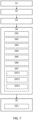
- the method comprises obtaining S1 information related to an upcoming vehicle path p and vehicle maneuver along the path.
- the path p may, for instance, be a stretch of road associated with a height profile 510 and perhaps also a section with reduced friction 520, as well as a turn maneuver m to be executed by the vehicle 100.
- a distance D of the path p may be between 50-1000 m, and preferably between 50-300 m or so.
- the vehicle maneuver m may, e.g., comprise a road speed limit to be adhered to, turning maneuvers, speed change maneuvers, and the like.
- the method optionally comprises obtaining S2 information related to a road friction coefficient ⁇ along the upcoming vehicle path p.
- the vehicle 100 either estimates a road friction coefficient ⁇ using on-board sensors such as cameras, infra-red sensors, and thermometers, or receives road friction reports from a remote server 530 by wireless link 540 via a radio base station 550.
- the method comprises configuring S3 lateral and longitudinal wheel slip limits ⁇ lim for at least two wheels of an axle 111, 151, 161, 162 or lumped group-axle 115, 125, 135, 145 on the heavy-duty vehicle 100a, 100b, wherein lateral and longitudinal wheel slip values are related to respective lateral and longitudinal tyre force values F x , F y via a pre-determined combined tyre slip model, such as that illustrated in Figure 4 .
- the wheel slip limits ⁇ lim may, e.g., be pre-configured by the vehicle manufacturer or by the tyre provider.
- the wheel slip limits may be interpreted as defining a constrained region 410, 420 as indicated in Figure 4 .
- the constrained region may be defined so as to ensure operation in the linear tyre force region where generated tyre force is an essentially linear function of wheel slip, where the wheel slip stiffness is indicative of the proportionality constant of this linear relationship.
- the longitudinal slip stiffness decreases with increasing lateral wheel slip
- the lateral wheel slip stiffness decreases with increasing longitudinal wheel slip. It is also appreciated that, for excessive longitudinal wheel slip, it is only possible to generate very small lateral tyre forces. Thus, if the vehicle enters into a turn with excessive longitudinal wheel slip, it becomes impossible to generate the required lateral wheel forces to successfully negotiate the turn.
- the method further comprises determining S4 a vehicle motion profile a for performing the vehicle maneuver m along the path p as a solution to a non-linear optimal control problem (NOCP).
- NOCP non-linear optimal control problem
- This NOCP is formulated so as to be constrained by the lateral and longitudinal wheel slip limits ⁇ lim and optionally also formulated to account for the road friction coefficient ⁇ along the upcoming vehicle path p.
- the objective function can, as will be discussed in more detail below comprise any number of performance metrics such as energy consumption, driver comfort including jerkiness, time to traverse the vehicle path, battery degradation, tyre wear, driver salary and the like.
- the objective function can also be a constant, i.e., 1, which means that all solutions to the NOCP which meet the constraints are considered equally good.
- controlling S5 the motion of the heavy-duty vehicle 100 along the path p based on the determined target vehicle motion profile a will not generate excessive wheel slip, which is an advantage.
- controlling S51 the motion of the heavy-duty vehicle 100a, 100b may be achieved by issuing any of: an acceleration request, a wheel torque request, and/or a wheel slip request, in dependence of the vehicle motion profile a to one or more actuator control units of the heavy-duty vehicle 100a, 100b.
- Figure 6A illustrates an example vehicle motion profile 600 which can be requested from, e.g., the VMM layer.
- This profile comprises an acceleration vector with longitudinal 610 and lateral 620 components which can be requested safely from the VMM function without risking excessive wheel slip.
- Figure 6B instead shows an example vehicle motion profile 650 comprising wheel slips 660, 670 of, e.g., the wheels of an axle. Note that the wheel slips stay within the constrained wheel slip region defined by the high and low wheel slip limits ⁇ lim-h and ⁇ lim-l .
- the method comprises determining S41 the vehicle motion profile a for performing the vehicle maneuver m along the path p as a solution to a NOCP which is configured to minimize an energy consumption by the vehicle along the path p.
- the vehicle looks ahead and plans optimal speed, battery state of charge, and tyre forces via control of the longitudinal and lateral tyre slips in an optimal manner.
- the NOCP can be defined as follows: Find Forces of Internal combustion engine (ICE), electric motors (EMs), brakes, and gears to minimize Objective function comprising, e.g., energy consumption (electric and/or diesel) over a prediction horizon 1.1 subject to conversion of the decision variables to the distributed lumped axles longitudinal forces, 1.2 (multitrailer) vehicle longitudinal dynamic equation, 1.3 (multitrailer) vehicle distributed lateral dynamic equations, 1.4 (any) tyre combined slip model for each lumped axle, 1.5 battery state of charge (SOC) dynamic, 1.6 time dynamic, 1.7 initial and terminal states, 1.8 ICE torque upper limit, 1.9 EM torque limits, 1.10 arrival time, 1.11 battery SOC limits, 1.12 battery power limits, 1.13 speed limits, 1.14 ICE torque (force) lower limit, 1.15 friction brake force (inaccurate) limits, 1.16 constraints on lateral and longitudinal slips of the all lumped axles 1.17 constraints on total tyre force of the all lumped
- ICE Internal combustion engine
- f x in general is not an invertible function, i.e., if F x , v x and v y are known, ⁇ cannot be directly calculated unless by numerical iterations.
- the states of the optimal control problem may comprise the first vehicle unit 110 longitudinal speed v x , first vehicle unit 110 lateral speed v y , first vehicle unit 110 yaw angle ⁇ 1 , and their time derivatives, articulation angles ⁇ 1 , ⁇ 2 , ⁇ 3 and their time derivatives, as well as the time t and state of charge SOC of batteries.
- the NOCP defined above can be solved based, e.g., on a model of a vehicle powertrain, as illustrated schematically in Figure 10 .
- dynamic equations of a parallel hybrid powertrain comprising one or more electric machines (EM) and internal combustion engines (ICE) can be derived, as can equations for evaluating fuel consumption, electric energy consumption, state of charge of batteries, and energy dissipated in different parts of the powertrain.
- EM electric machines
- ICE internal combustion engines
- conventional and fully electric powertrains can be derived from the equations of the hybrid powertrain in a straight-forward manner by setting weight parameters to effectively zero out contributions from the ICE or from the EM.
- m is the vehicle total mass or equivalent total mass
- s(t) is the travelled distance at time t
- F g is the road grade
- F roll is the rolling resistance
- F air is the air drag.
- F g s t ⁇ m g sin ⁇ p s t
- F roll s t m g f r cos ⁇ p s t
- air v x t 0.5 ⁇ a A f c d v x t 2
- g, ⁇ p , f r , ⁇ a , A f , and c d represent the gravitational constant, road grade (positive downhill), rolling resistance coefficient, air density, equivalent vehicle front area and air drag coefficient, respectively.
- F steer approximates all forces caused by steering and from the articulation angles, i.e., side slips of the tires, as well as the rotational inertia. This term is close to zero in straight road driving and is negligible for single-unit vehicles. However, for articulated vehicles on curved roads, the term cannot be neglected for accurate state and energy consumption estimations.
- P f , P e , P de , P ew , and P det denote, respectively, powers associated with the fuel tank, with the ICE output, dissipated by the ICE, at the ICE transmission output and dissipated in ICE transmission, respectively.
- P b , P db , P a , P mc , P dm , P m , P dmt , P mw represent the powers provided by or stored in the battery, dissipated in the battery, used for auxiliaries, consumed or regenerated by EM, dissipated in EM, at EM output/input to/from transmission, dissipated in EM transmission and at output/input to/from wheels, respectively.
- P br be the friction brake power.
- the power balance equation for each subsystem can be written as follows. A power balance can be assumed since there is no energy storage or generation inside the powertrain, except that in the fuel tank and battery, i.e., no inertial flywheels or elastic shafts are modelled.
- the power dissipation of the ICE and the EM can, e.g., be modelled by direct use of data from measured maps or by using high-degree nonlinear fitted curves. Measurements can, e.g., be performed for varying torques and angular speeds.
- R, r e , T e , ⁇ e , r m , T m , and ⁇ m denote the wheel radius, gear ratio from wheel to engine, engine torque, engine speed, gear ratio from wheel to EM, EM torque and EM speed, respectively.
- Other surface fitting functions can of course also be used with similar effect.
- transmission dissipation can be assumed to be linear with respect to the power input being independent of gear selection:
- P det P e t P e t ⁇ ⁇ te P e t P e t ⁇ 0
- P dmt P m t P m t ⁇ ⁇ tm P m t if P m t > 0 ⁇ P m t ⁇ tm ⁇ P m t if P m t ⁇ 0
- ⁇ te ⁇ tm represent the transmission efficiency of the ICE and the EM, respectively.
- the negative sign in the second part above is needed in order to keep P dmt positive.
- SOC state of charge
- F xx denote a force corresponding to the above-mentioned powers P xx (as illustrated, e.g., in Figure 10 ), ⁇ e is an integer gear of the ICE, ⁇ m is an integer gear of the EM, R w is wheel radius, V b 2 is the battery open circuit voltage, r e is the ICE gearbox and final ratio and r m is the EM gearbox and final ratio.
- ⁇ 1 , ⁇ 1 is the first vehicle unit 110 yaw angle and time derivate
- v x is the first vehicle unit 110 longitudinal speed
- v y is the first vehicle unit 110 lateral speed
- ⁇ 1 , ⁇ 2 , ⁇ 3 , ⁇ 1 , ⁇ 2 , ⁇ 3 are articulation angles and their time derivatives
- t is time
- SOC is the state of charge of the battery system.
- a u maps the EMS inputs (decision variables) to the input forces used in the lateral dynamics model.
- the lateral dynamics model can be according to the article
- the input-output system of the above approach can be described as follows.
- the vehicle motion profile comprises a target tyre force trajectory and/or a target wheel slip trajectory for at least two wheels to be followed along the upcoming vehicle path p.
- the vehicle motion profile a may also, as mentioned above, comprise a target vehicle unit acceleration and/or a target vehicle speed to be followed along the upcoming vehicle path p.
- Both the target force trajectory and the acceleration profile have been generated under slip constraints, which means that they are safe in the meaning that the vehicle can be controlled to behave according to the target forces trajectory and/or the acceleration profile without experiencing wheel slip in excess of the configured slip limits.
- Solving the NOCP may in some cases be associated with prohibitive computational complexity. To reduce the computational complexity and thereby allow real-time vehicle control based on processing of NOCP solutions, some complexity reducing steps may be taken.
- the method may comprise any of: Converting S42 the NOCP to a sequential program and determining the vehicle motion profile as a solution to the sequential program.
- methods comprising model predictive control (linear or nonlinear) can be used with advantage.
- Configuring S45 two different levels of discretization for longitudinal and lateral dynamic equations of the NOCP, preferably a first discretization for the longitudinal dynamic equations of the NOCP and a second discretization for the lateral dynamic equations of the NOCP, wherein the first discretization is more coarse than the second discretization.
- DAE differential-algebraic system of equations
- FIG. 8 schematically illustrates, in terms of a number of functional units, the components of a control unit 240 according to embodiments of the discussions and methods disclosed herein.
- This control unit 240 may be comprised in the vehicle 100a, 100b, e.g., in the form of a vehicle motion management (VMM) unit configured to perform force allocation and the like.
- VMM vehicle motion management
- Processing circuitry 810 is provided using any combination of one or more of a suitable central processing unit CPU, multiprocessor, microcontroller, digital signal processor DSP, etc., capable of executing software instructions stored in a computer program product, e.g. in the form of a storage medium 830.
- the processing circuitry 810 may further be provided as at least one application specific integrated circuit ASIC, or field programmable gate array FPGA.
- the processing circuitry 810 is configured to cause the control unit 240 to perform a set of operations, or steps, such as the methods discussed in connection to Figure 7 .
- the storage medium 830 may store the set of operations
- the processing circuitry 810 may be configured to retrieve the set of operations from the storage medium 830 to cause the control unit 240 to perform the set of operations.
- the set of operations may be provided as a set of executable instructions.
- the processing circuitry 810 is thereby arranged to execute methods as herein disclosed.
- the storage medium 830 may also comprise persistent storage, which, for example, can be any single one or combination of magnetic memory, optical memory, solid state memory or even remotely mounted memory.
- the control unit 240 may further comprise an interface 820 for communications with at least one external device, such as an electric machine or a gearbox.
- the interface 820 may comprise one or more transmitters and receivers, comprising analogue and digital components and a suitable number of ports for wireline or wireless communication.
- the processing circuitry 810 controls the general operation of the control unit 240, e.g., by sending data and control signals to the interface 820 and the storage medium 830, by receiving data and reports from the interface 820, and by retrieving data and instructions from the storage medium 830.
- Other components, as well as the related functionality, of the control node are omitted in order not to obscure the concepts presented herein.
- Figure 9 illustrates a computer readable medium 910 carrying a computer program comprising program code means 920 for performing, e.g., the methods illustrated in Figure 7 , when said program product is run on a computer.
- the computer readable medium and the code means may together form a computer program product 900.
Landscapes
- Engineering & Computer Science (AREA)
- Mechanical Engineering (AREA)
- Transportation (AREA)
- Chemical & Material Sciences (AREA)
- Combustion & Propulsion (AREA)
- Automation & Control Theory (AREA)
- General Engineering & Computer Science (AREA)
- Vehicle Body Suspensions (AREA)
- Electric Propulsion And Braking For Vehicles (AREA)
- Control Of Driving Devices And Active Controlling Of Vehicle (AREA)
Claims (18)
- Verfahren zum Steuern einer Bewegung eines Schwerlastfahrzeugs (100a, 100b), umfassend:Erhalten (S1) von Informationen in Bezug auf einen bevorstehenden Fahrzeugweg (p) und ein Fahrzeugmanöver (m) entlang des Weges,Konfigurieren (S3) von lateralen und longitudinalen Radschlupfgrenzen (λ lim ) für mindestens zwei Räder einer Achse (111, 151, 161, 162) oder Gruppenachse (115, 125, 135, 145) an dem Schwerlastfahrzeug (100a, 100b), wobei laterale und longitudinale Radschlupfwerte mit den jeweiligen lateralen und longitudinalen Reifenkraftwerten (Fx, Fy) über ein vorbestimmtes kombiniertes Reifenschlupfmodell in Beziehung stehen,Bestimmen (S4) eines Soll-Fahrzeugbewegungsprofils (a) zur Durchführung des Fahrzeugmanövers (m) entlang des Weges (p), undSteuern (S5) der Bewegung des Schwerlastfahrzeugs (100a, 100b) entlang des Weges (p) auf der Grundlage des ermittelten Soll-Fahrzeugbewegungsprofils (a),dadurch gekennzeichnet, dass dasSoll-Fahrzeugbewegungsprofil (a) als Lösung eines nichtlinearen optimalen Steuerungsproblems (NOCP) bestimmt wird, wobei das NOCP durch die seitlichen und längsseitigen Radschlupfgrenzen (λlim ) eingeschränkt ist.
- Verfahren nach Anspruch 1, umfassend das Erhalten (S2) von Informationen bezüglich eines Straßenreibungskoeffizienten (µ) und/oder eine Krümmung entlang des bevorstehenden Fahrzeugwegs (p), wobei das NOCP so ausgelegt ist, dass es den Straßenreibungskoeffizienten (µ) und/oder die Krümmung entlang des bevorstehenden Fahrzeugwegs (p) berücksichtigt.
- Verfahren nach Anspruch 1 oder 2, wobei das Fahrzeugbewegungsprofil (a) eine Soll-Reifenkrafttrajektorie und/oder eine Soll-Radschlupftrajektorie für mindestens zwei Räder umfasst, die entlang des bevorstehenden Fahrzeugwegs (p) zu verfolgen sind.
- Verfahren nach Anspruch 1 oder 2, wobei das Fahrzeugbewegungsprofil (a) eine Soll-Fahrzeugbeschleunigung und/oder eine Soll-Fahrzeuggeschwindigkeit umfasst, die auf dem bevorstehenden Fahrzeugweg (p) einzuhalten ist.
- Verfahren nach einem der vorstehenden Ansprüche, wobei das Schwerlastfahrzeug (100a, 100b) einen Antriebsaktuator mit regenerativer Bremsfähigkeit an mehr als einer angetriebenen Achse umfasst.
- Verfahren nach einem der vorstehenden Ansprüche, wobei das Schwerlastfahrzeug ein Multitrailer-Fahrzeug (100a) ist, das eine selbstfahrende Transportwagen-Einheit (130) umfasst.
- Verfahren nach einem der vorstehenden Ansprüche, umfassend das Bestimmen (S41) des Fahrzeugbewegungsprofils (a) zum Ausführen des Fahrzeugmanövers (m) entlang des Weges (p) als Lösung für ein nichtlineares optimales Steuerungsproblem, NOCP, wobei das NOCP so konfiguriert ist, um einen Energieverbrauch des Fahrzeugs entlang der Strecke (p) zu minimieren.
- Verfahren nach einem der vorstehenden Ansprüche, umfassend das Umwandeln (S42) des NOCP in ein sequentielles Programm und das Bestimmen des Fahrzeugbewegungsprofils (a) als Lösung für das sequentielle Programm.
- Verfahren nach einem der vorstehenden Ansprüche, umfassend das Konfigurieren (S43) eines nichtlinearen einspurigen Fahrzeugmodells des Schwerlastfahrzeugs (100a, 100b) mit Gruppenachsen (115, 125, 135, 145, 155).
- Verfahren nach einem der vorstehenden Ansprüche, umfassend das Reduzieren (S44) einer Anzahl von Zuständen in einer oder mehreren längsdynamischen Gleichungen des NOCP.
- Verfahren nach einem der vorstehenden Ansprüche, umfassend das Konfigurieren (S45) von zwei unterschiedlichen Diskretisierungsebenen für die longitudinalen und lateralen dynamischen Gleichungen des NOCP, vorzugsweise eine erste Diskretisierung für die longitudinalen dynamischen Gleichungen des NOCP und eine zweite Diskretisierung für die lateralen dynamischen Gleichungen des NOCP, wobei die erste Diskretisierung gröber ist als die zweite Diskretisierung.
- Verfahren nach einem der vorstehenden Ansprüche, umfassend das Konfigurieren (S46) einer linearen zeitvarianten LTV-Version der lateralen dynamischen Gleichungen des NOCP und/oder des kombinierten Reifenschlupfmodells, wobei die LTV um ein anfängliches Referenz-Fahrzeugbewegungsprofil entlang des Weges (p) linearisiert wird.
- Verfahren nach einem der vorstehenden Ansprüche, umfassendLösen (S471) eines differential-algebraischen Gleichungssystems, DAE, das algebraische Gleichungen des kombinierten Reifenschlupfmodells jeder Achse eines Satzes von Einzelachsen des Schwerlastfahrzeugs (100a, 100b) umfasst, um Radgeschwindigkeits-Referenztrajektorien für jede Achse des Schwerlastfahrzeugs (100a, 100b) zu finden.Linearisieren (S472) der algebraischen Längsgleichungen Fx = fx (vx, vy, ω) jeder der Einzelachsen um die entsprechende Radgeschwindigkeits- Referenztrajektorie und symbolisches Lösen der resultierenden linearisierten Gleichungen für die Radgeschwindigkeit, so dass
 Ersetzen (S473) der Ausdrücke für die Radgeschwindigkeit ω durch jeweilige Ausdrücke für die seitliche Reifenkraft Fy = fv (vx, vy, ω).
 - Verfahren nach einem der vorstehenden Ansprüche, wobei eine Distanz des Weges (p) zwischen 5-1000 m und vorzugsweise zwischen 50-300 m beträgt.
- Verfahren nach einem der vorstehenden Ansprüche, wobei das Fahrzeugmanöver (m) eine einzuhaltende Geschwindigkeitsbegrenzung auf der Straße umfasst.
- Verfahren nach einem der vorstehenden Ansprüche, umfassend das Steuern (S51) der Bewegung des Schwerlastfahrzeugs (100a, 100b) durch Ausgeben einer Beschleunigungsanforderung, einer Raddrehmomentanforderung und/oder einer Radschlupfanforderung in Abhängigkeit von dem Fahrzeugbewegungsprofil (a) an eine oder mehrere Aktuatorsteuereinheiten des Schwerlastfahrzeugs (100a, 100b).
- Steuereinheit (240) mit einer Verarbeitungsschaltung (810), die so konfiguriert ist, dass sie ein Verfahren nach einem der vorstehenden Ansprüche ausführt.
- Schwelastfahrzeug (100a, 100b) umfassend die Steuereinheit (240) nach Anspruch 17.
Applications Claiming Priority (1)
| Application Number | Priority Date | Filing Date | Title |
|---|---|---|---|
| PCT/EP2020/082707 WO2022106004A1 (en) | 2020-11-19 | 2020-11-19 | Predictive energy and motion management for multitrailer heavy-duty vehicles |
Publications (3)
| Publication Number | Publication Date |
|---|---|
| EP4247695A1 EP4247695A1 (de) | 2023-09-27 |
| EP4247695C0 EP4247695C0 (de) | 2024-12-25 |
| EP4247695B1 true EP4247695B1 (de) | 2024-12-25 |
Family
ID=73554416
Family Applications (1)
| Application Number | Title | Priority Date | Filing Date |
|---|---|---|---|
| EP20811984.2A Active EP4247695B1 (de) | 2020-11-19 | 2020-11-19 | Prädiktive energie- und bewegungsverwaltung für schwerlastfahrzeuge mit mehreren aufliegern |
Country Status (5)
| Country | Link |
|---|---|
| US (1) | US12570290B2 (de) |
| EP (1) | EP4247695B1 (de) |
| KR (1) | KR20230109146A (de) |
| CN (1) | CN116457270A (de) |
| WO (1) | WO2022106004A1 (de) |
Cited By (1)
| Publication number | Priority date | Publication date | Assignee | Title |
|---|---|---|---|---|
| US12617388B2 (en) * | 2021-12-20 | 2026-05-05 | Volvo Truck Corporation | Predictive heavy-duty vehicle motion management based on environment sensing |
Families Citing this family (22)
| Publication number | Priority date | Publication date | Assignee | Title |
|---|---|---|---|---|
| EP4001029A1 (de) * | 2020-11-16 | 2022-05-25 | Volvo Truck Corporation | Fahrzeugbewegungsmanagementsystem und aktuatorsteuerungssystem für ein fahrzeug |
| US12162494B2 (en) * | 2020-11-19 | 2024-12-10 | Volvo Truck Corporation | Methods for reducing high-speed off-tracking in multi-trailer heavy duty vehicles |
| KR20230109146A (ko) * | 2020-11-19 | 2023-07-19 | 볼보 트럭 코퍼레이션 | 멀티트레일러 중량 차량들을 위한 예측 에너지 및 모션 관리 |
| WO2023046259A1 (en) * | 2021-09-21 | 2023-03-30 | Volvo Truck Corporation | Wheel slip-based motion control for heavy-duty vehicles |
| EP4536517A1 (de) * | 2022-06-06 | 2025-04-16 | Volvo Truck Corporation | Verfahren zur steuerung einer fahrzeugkombination |
| EP4540091A1 (de) * | 2022-06-20 | 2025-04-23 | Volvo Truck Corporation | Steuerung der auf einen anhänger angewandten kraft pro radpaar |
| CN119421819A (zh) * | 2022-06-23 | 2025-02-11 | 沃尔沃卡车集团 | 用于确定牵引车纵向力阈值的方法 |
| EP4601917A1 (de) * | 2022-10-11 | 2025-08-20 | Volvo Truck Corporation | Verfahren zur bremssteuerung eines fahrzeugs |
| EP4368462B1 (de) * | 2022-11-11 | 2025-08-20 | Volvo Truck Corporation | Schwerlastfahrzeug |
| CN116175286B (zh) * | 2022-12-14 | 2025-07-22 | 佛山纽欣肯智能科技有限公司 | 一种基于dmp的复杂曲面打磨轨迹规划方法 |
| WO2024213246A1 (en) * | 2023-04-13 | 2024-10-17 | Volvo Truck Corporation | Power control for combination vehicles |
| EP4695108A1 (de) * | 2023-04-13 | 2026-02-18 | Volvo Truck Corporation | Leistungsregelung für fahrzeuge |
| US12246747B2 (en) * | 2023-05-31 | 2025-03-11 | Plusai, Inc. | Adaptive and fuel efficient planning and control |
| CN116654101B (zh) * | 2023-07-18 | 2025-11-25 | 一汽解放汽车有限公司 | 鞍座底板、车辆驱动轮载荷调节方法及车辆 |
| WO2025061281A1 (en) * | 2023-09-20 | 2025-03-27 | Volvo Truck Corporation | Slip control for a vehicle |
| WO2025131299A1 (en) * | 2023-12-22 | 2025-06-26 | Volvo Autonomous Solutions AB | System and method for controlling traction and brake distribution |
| EP4610135B1 (de) * | 2024-03-01 | 2026-04-08 | Volvo Truck Corporation | Auswahl eines steuergeräts für ein fahrzeug |
| EP4613510A1 (de) | 2024-03-07 | 2025-09-10 | Volvo Truck Corporation | Reifenverschleissmanagement für ein fahrzeug |
| EP4613585A1 (de) * | 2024-03-07 | 2025-09-10 | Volvo Truck Corporation | System und verfahren zum reifenverschleissmanagement für ein fahrzeug |
| EP4613596A1 (de) | 2024-03-07 | 2025-09-10 | Volvo Truck Corporation | Reifenverschleissmanagement für ein fahrzeug |
| US20260008478A1 (en) * | 2024-07-03 | 2026-01-08 | GM Global Technology Operations LLC | Vehicle control combining neural network and physics prediction |
| EP4691863A1 (de) * | 2024-08-07 | 2026-02-11 | Volvo Truck Corporation | Bestimmung einer längsrutschgrenze eines fahrzeugs |
Citations (10)
| Publication number | Priority date | Publication date | Assignee | Title |
|---|---|---|---|---|
| DE19521544A1 (de) | 1995-06-13 | 1996-12-19 | Wabco Gmbh | Verfahren zur wenigstens näherungsweisen Ermittlung des bei wenigstens einer Bremsung zwischen den Rädern eines Fahrzeugs und der Fahrbahn ausgenutzten Reibwertes |
| US20060055239A1 (en) | 2004-09-13 | 2006-03-16 | Crombez Dale S | Method for operating multiple axle regenerative braking in an automotive vehicle |
| DE102006017412A1 (de) | 2006-04-13 | 2007-10-18 | Zf Friedrichshafen Ag | Verfahren zum Steuern mehrerer die Fahrdynamik eines Fahrzeuges beeinflussender Fahrzeugkomponenten |
| US9096226B2 (en) | 2013-10-31 | 2015-08-04 | Ford Global Technologies, Llc | Vehicle dynamic controls coordination system for dual-axle driven electric vehicles |
| GB2562308A (en) | 2017-05-12 | 2018-11-14 | Arrival Ltd | Regenerative braking control system |
| DE102017211485A1 (de) | 2017-07-05 | 2019-01-10 | Continental Teves Ag & Co. Ohg | Verfahren und Vorrichtung zum Steuern eines Fahrzeugs |
| US10518831B2 (en) | 2017-04-21 | 2019-12-31 | Wrightspeed, Inc. | Self-powered actively steerable converter dollies for long combination vehicles |
| WO2020083465A1 (en) | 2018-10-22 | 2020-04-30 | Volvo Truck Corporation | Method for having a vehicle follow a desired curvature path |
| US20200298878A1 (en) | 2017-10-10 | 2020-09-24 | Commissariat A L'energie Atomique Et Aux Energies Alternatives | Method for automatically driving a vehicle under constraint, in particular a bus in a storage facility, and device implementing such a method |
| DE102019205947A1 (de) | 2019-04-25 | 2020-10-29 | Robert Bosch Gmbh | Verfahren zur Regelung der Fahrzeuggeschwindigkeit insbesondere für ein autonom betriebenes Fahrzeug |
Family Cites Families (19)
| Publication number | Priority date | Publication date | Assignee | Title |
|---|---|---|---|---|
| EP0798615B1 (de) * | 1996-02-27 | 2002-01-02 | KNORR-BREMSE SYSTEME FÜR NUTZFAHRZEUGE GmbH | Verfahren zur Fahrstabilitätserhöhung |
| JP4268019B2 (ja) * | 2003-11-14 | 2009-05-27 | 株式会社豊田中央研究所 | 車体運動実現方法及び装置 |
| DE102009030784A1 (de) * | 2009-06-27 | 2010-02-04 | Daimler Ag | Verfahren zum Steuern des Betriebs eines Fahrzeugs |
| US9514647B2 (en) * | 2010-10-20 | 2016-12-06 | GM Global Technology Operations LLC | Optimal acceleration profile for enhanced collision avoidance |
| US9037346B2 (en) * | 2011-09-23 | 2015-05-19 | Deere & Company | Steering control for vehicle trains |
| WO2016020834A1 (en) * | 2014-08-04 | 2016-02-11 | Modelway S.R.L. | A method for estimating variables affecting the vehicle dynamics and corresponding virtual sensor |
| US10011284B2 (en) * | 2016-07-13 | 2018-07-03 | Mitsubishi Electric Research Laboratories, Inc. | System and method for determining state of stiffness of tires of vehicle |
| SE541795C2 (en) * | 2017-09-22 | 2019-12-17 | Sentient Ip Ab | Method and system for controlling vehicle lane holding |
| US12221101B2 (en) * | 2018-03-04 | 2025-02-11 | Traxen Inc. | Automated cruise control system |
| CN110605973B (zh) * | 2019-09-18 | 2021-08-03 | 北京理工大学 | 一种基于分层结构的多轴分布式电驱动车辆操纵稳定性控制方法 |
| EP3995372A1 (de) * | 2020-11-09 | 2022-05-11 | Volvo Truck Corporation | Verfahren zur steuerung eines aktuators eines fahrzeugs |
| CN111452781B (zh) * | 2020-03-24 | 2023-01-17 | 东南大学 | 一种改善加速舒适性的轮毂电机驱动电动汽车强鲁棒自适应驱动防滑控制方法 |
| US12162494B2 (en) * | 2020-11-19 | 2024-12-10 | Volvo Truck Corporation | Methods for reducing high-speed off-tracking in multi-trailer heavy duty vehicles |
| KR20230109146A (ko) * | 2020-11-19 | 2023-07-19 | 볼보 트럭 코퍼레이션 | 멀티트레일러 중량 차량들을 위한 예측 에너지 및 모션 관리 |
| US12311975B2 (en) * | 2022-08-19 | 2025-05-27 | Mitsubishi Electric Research Laboratories, Inc. | System and method for controlling movement of a vehicle |
| CN115384529B (zh) * | 2022-09-20 | 2025-11-07 | 江苏大学 | 一种应对极限工况的三轴商用车双阶段漂移控制方法及安全辅助系统 |
| CN116279408B (zh) * | 2023-02-03 | 2025-12-12 | 同济大学 | 一种基于快速求解算法的车辆纵侧向运动协同控制方法 |
| US12286151B1 (en) * | 2023-03-24 | 2025-04-29 | Mitsubishi Electric Research Laboratories, Inc. | System and method for controlling motion of articulated vehicles |
| WO2025103589A1 (en) * | 2023-11-15 | 2025-05-22 | Volvo Truck Corporation | Wheel slip control |
-
2020
- 2020-11-19 KR KR1020237017192A patent/KR20230109146A/ko not_active Ceased
- 2020-11-19 WO PCT/EP2020/082707 patent/WO2022106004A1/en not_active Ceased
- 2020-11-19 EP EP20811984.2A patent/EP4247695B1/de active Active
- 2020-11-19 US US18/253,365 patent/US12570290B2/en active Active
- 2020-11-19 CN CN202080107338.0A patent/CN116457270A/zh active Pending
Patent Citations (10)
| Publication number | Priority date | Publication date | Assignee | Title |
|---|---|---|---|---|
| DE19521544A1 (de) | 1995-06-13 | 1996-12-19 | Wabco Gmbh | Verfahren zur wenigstens näherungsweisen Ermittlung des bei wenigstens einer Bremsung zwischen den Rädern eines Fahrzeugs und der Fahrbahn ausgenutzten Reibwertes |
| US20060055239A1 (en) | 2004-09-13 | 2006-03-16 | Crombez Dale S | Method for operating multiple axle regenerative braking in an automotive vehicle |
| DE102006017412A1 (de) | 2006-04-13 | 2007-10-18 | Zf Friedrichshafen Ag | Verfahren zum Steuern mehrerer die Fahrdynamik eines Fahrzeuges beeinflussender Fahrzeugkomponenten |
| US9096226B2 (en) | 2013-10-31 | 2015-08-04 | Ford Global Technologies, Llc | Vehicle dynamic controls coordination system for dual-axle driven electric vehicles |
| US10518831B2 (en) | 2017-04-21 | 2019-12-31 | Wrightspeed, Inc. | Self-powered actively steerable converter dollies for long combination vehicles |
| GB2562308A (en) | 2017-05-12 | 2018-11-14 | Arrival Ltd | Regenerative braking control system |
| DE102017211485A1 (de) | 2017-07-05 | 2019-01-10 | Continental Teves Ag & Co. Ohg | Verfahren und Vorrichtung zum Steuern eines Fahrzeugs |
| US20200298878A1 (en) | 2017-10-10 | 2020-09-24 | Commissariat A L'energie Atomique Et Aux Energies Alternatives | Method for automatically driving a vehicle under constraint, in particular a bus in a storage facility, and device implementing such a method |
| WO2020083465A1 (en) | 2018-10-22 | 2020-04-30 | Volvo Truck Corporation | Method for having a vehicle follow a desired curvature path |
| DE102019205947A1 (de) | 2019-04-25 | 2020-10-29 | Robert Bosch Gmbh | Verfahren zur Regelung der Fahrzeuggeschwindigkeit insbesondere für ein autonom betriebenes Fahrzeug |
Non-Patent Citations (18)
| Title |
|---|
| "Master's Thesis, Chalmers University of Technology", 1 January 2016, article KÄLLSTRAND BJÖRN: "Control Allocation for Vehicle Motion Control: Maximizing Traction and Steering Capabilities Under Different Road Conditions ", XP093321481 |
| "Master's Thesis, Chalmers University of Technology", 1 January 2018, article PEREIRA BARROS IURI: "Energy consumption, Performance and Stability Analysis of Articulated Vehicles Powered with Electrified Dolly ", XP093321472 |
| ALSTERDA JOHN P.; BROWN MATTHEW; GERDES J. CHRISTIAN: "Contingency Model Predictive Control for Automated Vehicles", 2019 AMERICAN CONTROL CONFERENCE (ACC), AMERICAN AUTOMATIC CONTROL COUNCIL, 10 July 2019 (2019-07-10), pages 717 - 722, XP033605598 |
| ANONYMOUS: "Antiblockiersystem", WIKIPEDIA, 25 October 2020 (2020-10-25), pages 1 - 10, XP093290438, Retrieved from the Internet <URL:https://de.wikipedia.org/w/index.php?title=Antiblockiersystem&oldid=204884681> |
| ANONYMOUS: "Circle of forces", WIKIPEDIA, 13 September 2020 (2020-09-13), XP093321530, Retrieved from the Internet <URL:https://en.wikipedia.org/w/index.php?title=Circle_of_forces&oldid=978275805> |
| ANONYMOUS: "Fahrdynamikregelung", WIKIPEDIA, 26 October 2020 (2020-10-26), XP093321492, Retrieved from the Internet <URL:https://de.wikipedia.org/w/index.php?title=Fahrdynamikregelung&oldid=204920052> |
| ANONYMOUS: "Kammscher Kreis", WIKIPEDIA, 25 April 2019 (2019-04-25), XP093321486, Retrieved from the Internet <URL:https://de.wikipedia.org/w/index.php?title=Kammscher_Kreis&oldid=187908759> |
| ANONYMOUS: "Model predictive control", WIKIPEDIA, 12 November 2020 (2020-11-12), XP093321527, Retrieved from the Internet <URL:https://en.wikipedia.org/w/index.php?title=Model_predictive_control&oldid=988269842> |
| ANONYMOUS: "Optimal control", WIKIPEDIA, 12 November 2020 (2020-11-12), XP093321520, Retrieved from the Internet <URL:https://en.wikipedia.org/w/index.php?title=Optimal_control&oldid=988274264> |
| ANONYMOUS: "Optimale Regelung ", WIKIPEDIA, 29 July 2020 (2020-07-29), XP093321495, Retrieved from the Internet <URL:https://de.wikipedia.org/w/index.php?title=Optimale_Regelung&oldid=202333832"> |
| CHEN CHANGFANG; JIA YINGMIN; SHU MINGLEI; WANG YINGLONG: "Hierarchical Adaptive Path-Tracking Control for Autonomous Vehicles", IEEE TRANSACTIONS ON INTELLIGENT TRANSPORTATION SYSTEMS, IEEE, PISCATAWAY, NJ, USA, vol. 16, no. 5, 1 October 2015 (2015-10-01), Piscataway, NJ, USA , pages 2900 - 2912, XP011670197, ISSN: 1524-9050, DOI: 10.1109/TITS.2015.2426211 |
| D15a - Nachweis fur die Publikation von D15: Die Stanford University hat in D15a auf die D15 als Publikation in der Konferenz AVEC 2018 verwiesen, zuganglich unter https://ddl.stanford.edu/publications/conference- proceeding/controller-automated-driftingalong- complex-trajectories |
| D18a - Nachweis der Publikation von D18 auf der ACC 2019: "Contingency Model Predictive Control for Automated Vehicles" - IEEE Conference Publication - IEEE Xplore, zuganglich unter https://ieeexplore.ieee.org/document/8815260 |
| GOH JONATHAN Y, GOEL T, GERDES J CHRISTIAN: "A Controller for Automated Drifting Along Complex Trajectories", AVEC 2018, 1 January 2018 (2018-01-01), XP093321523, Retrieved from the Internet <URL:https://ddl.stanford.edu/sites/g/files/sbiybj25996/files/media/file/marty_avec2018_fullpaper_0.pdf> |
| JULIAN P. TIMINGS ; DAVID J. COLE: "Efficient minimum manoeuvre time optimisation of an oversteering vehicle at constant forward speed", 2011 AMERICAN CONTROL CONFERENCE (ACC 2011) : SAN FRANCISCO, CALIFORNIA, USA, 29 JUNE - 1 JULY 2011, IEEE, PISCATAWAY, NJ, 29 June 2011 (2011-06-29), Piscataway, NJ , pages 5267 - 5272, XP032034839, ISBN: 978-1-4577-0080-4 |
| KRID MOHAMED; BENAMAR FAIZ; LENAIN ROLAND: "A new explicit dynamic path tracking controller using generalized predictive control", INTERNATIONAL JOURNAL OF CONTROL, AUTOMATION AND SYSTEMS, KOREAN INSTITUTE OF ELECTRICAL ENGINEERS, SEOUL, KR, vol. 15, no. 1, 23 December 2016 (2016-12-23), KR , pages 303 - 314, XP036139469, ISSN: 1598-6446, DOI: 10.1007/s12555-015-0160-6 |
| KRISADA (MICK) KRITAYAMA: "AUTONOMOUS VEHICLE CONTROL AT THE LIMITS OF HANDLING", 30 June 2012 (2012-06-30), XP055760849, Retrieved from the Internet <URL:https://ddl.stanford.edu/sites/default/files/publications/2012_Thesis_Kritayakirana_Autonomous_Vehicle_Control_at_the_Limits_of_Handling.pdf> [retrieved on 20201217] |
| SIAMPIS EFSTATHIOS, VELENIS EFSTATHIOS, GARIUOLO SALVATORE, LONGO STEFANO: "A Real-Time Nonlinear Model Predictive Control Strategy for Stabilization of an Electric Vehicle at the Limits of Handling", IEEE TRANSACTIONS ON CONTROL SYSTEMS TECHNOLOGY., IEEE SERVICE CENTER, NEW YORK, NY., US, vol. 26, no. 6, 1 November 2018 (2018-11-01), US , pages 1982 - 1994, XP093321522, ISSN: 1063-6536, DOI: 10.1109/TCST.2017.2753169 |
Cited By (1)
| Publication number | Priority date | Publication date | Assignee | Title |
|---|---|---|---|---|
| US12617388B2 (en) * | 2021-12-20 | 2026-05-05 | Volvo Truck Corporation | Predictive heavy-duty vehicle motion management based on environment sensing |
Also Published As
| Publication number | Publication date |
|---|---|
| CN116457270A (zh) | 2023-07-18 |
| WO2022106004A1 (en) | 2022-05-27 |
| EP4247695A1 (de) | 2023-09-27 |
| US12570290B2 (en) | 2026-03-10 |
| EP4247695C0 (de) | 2024-12-25 |
| US20240001928A1 (en) | 2024-01-04 |
| KR20230109146A (ko) | 2023-07-19 |
Similar Documents
| Publication | Publication Date | Title |
|---|---|---|
| EP4247695B1 (de) | Prädiktive energie- und bewegungsverwaltung für schwerlastfahrzeuge mit mehreren aufliegern | |
| EP4247686B1 (de) | Verfahren zur reduzierung von hochgeschwindigkeits-off-tracking in schwerlastfahrzeugen mit mehreren anhängern | |
| EP4140839B1 (de) | Fahrzeugsteuerung basierend auf einer dynamisch konfigurierten seitenschlupfgrenze | |
| EP4117953B1 (de) | Verfahren zur steuerung eines leistungspegels in einer energiequelle einer fahrzeugeinheit | |
| EP4103453B1 (de) | Verfahren zur steuerung eines selbstfahrenden rollwagenfahrzeugs während eines ausweichmanövers | |
| EP4330097B1 (de) | Fahrzeugsteuerung auf basis dynamisch konfigurierter längsradschlupfgrenzen | |
| EP4347302B1 (de) | Energieeffizienter antrieb auf basis eines radschlupfausgeglichenen antriebs | |
| JP2024514554A (ja) | 大型車両を制動するための方法及び装置 | |
| US20240359706A1 (en) | Vehicle control for simplified autonomous drive | |
| Guastadisegni et al. | Vehicle stability control through pre-emptive braking | |
| EP4219252B1 (de) | Verfahren zur steuerung eines schwerlastfahrzeugs | |
| US20250242817A1 (en) | Control barrier functions for safety-critical control of automotive stability | |
| EP4714770A1 (de) | Schätzung von seitenschlupfverlusten in einer fahrzeugkombination | |
| EP4714790A1 (de) | Lenksteuerung für nachlaufaggregate von fahrzeuggespannen | |
| WO2024213253A1 (en) | Braking control for vehicles | |
| EP4695122A1 (de) | Leistungsregelung für kombinationsfahrzeuge | |
| EP4695108A1 (de) | Leistungsregelung für fahrzeuge |
Legal Events
| Date | Code | Title | Description |
|---|---|---|---|
| STAA | Information on the status of an ep patent application or granted ep patent |
Free format text: STATUS: UNKNOWN |
|
| STAA | Information on the status of an ep patent application or granted ep patent |
Free format text: STATUS: THE INTERNATIONAL PUBLICATION HAS BEEN MADE |
|
| PUAI | Public reference made under article 153(3) epc to a published international application that has entered the european phase |
Free format text: ORIGINAL CODE: 0009012 |
|
| STAA | Information on the status of an ep patent application or granted ep patent |
Free format text: STATUS: REQUEST FOR EXAMINATION WAS MADE |
|
| 17P | Request for examination filed |
Effective date: 20230426 |
|
| AK | Designated contracting states |
Kind code of ref document: A1 Designated state(s): AL AT BE BG CH CY CZ DE DK EE ES FI FR GB GR HR HU IE IS IT LI LT LU LV MC MK MT NL NO PL PT RO RS SE SI SK SM TR |
|
| DAV | Request for validation of the european patent (deleted) | ||
| DAX | Request for extension of the european patent (deleted) | ||
| GRAP | Despatch of communication of intention to grant a patent |
Free format text: ORIGINAL CODE: EPIDOSNIGR1 |
|
| STAA | Information on the status of an ep patent application or granted ep patent |
Free format text: STATUS: GRANT OF PATENT IS INTENDED |
|
| INTG | Intention to grant announced |
Effective date: 20240723 |
|
| GRAS | Grant fee paid |
Free format text: ORIGINAL CODE: EPIDOSNIGR3 |
|
| GRAA | (expected) grant |
Free format text: ORIGINAL CODE: 0009210 |
|
| STAA | Information on the status of an ep patent application or granted ep patent |
Free format text: STATUS: THE PATENT HAS BEEN GRANTED |
|
| AK | Designated contracting states |
Kind code of ref document: B1 Designated state(s): AL AT BE BG CH CY CZ DE DK EE ES FI FR GB GR HR HU IE IS IT LI LT LU LV MC MK MT NL NO PL PT RO RS SE SI SK SM TR |
|
| REG | Reference to a national code |
Ref country code: GB Ref legal event code: FG4D |
|
| REG | Reference to a national code |
Ref country code: CH Ref legal event code: EP |
|
| REG | Reference to a national code |
Ref country code: DE Ref legal event code: R096 Ref document number: 602020043764 Country of ref document: DE |
|
| REG | Reference to a national code |
Ref country code: IE Ref legal event code: FG4D |
|
| U01 | Request for unitary effect filed |
Effective date: 20250110 |
|
| U07 | Unitary effect registered |
Designated state(s): AT BE BG DE DK EE FI FR IT LT LU LV MT NL PT RO SE SI Effective date: 20250116 |
|
| PG25 | Lapsed in a contracting state [announced via postgrant information from national office to epo] |
Ref country code: HR Free format text: LAPSE BECAUSE OF FAILURE TO SUBMIT A TRANSLATION OF THE DESCRIPTION OR TO PAY THE FEE WITHIN THE PRESCRIBED TIME-LIMIT Effective date: 20241225 |
|
| PG25 | Lapsed in a contracting state [announced via postgrant information from national office to epo] |
Ref country code: NO Free format text: LAPSE BECAUSE OF FAILURE TO SUBMIT A TRANSLATION OF THE DESCRIPTION OR TO PAY THE FEE WITHIN THE PRESCRIBED TIME-LIMIT Effective date: 20250325 |
|
| PG25 | Lapsed in a contracting state [announced via postgrant information from national office to epo] |
Ref country code: GR Free format text: LAPSE BECAUSE OF FAILURE TO SUBMIT A TRANSLATION OF THE DESCRIPTION OR TO PAY THE FEE WITHIN THE PRESCRIBED TIME-LIMIT Effective date: 20250326 |
|
| PG25 | Lapsed in a contracting state [announced via postgrant information from national office to epo] |
Ref country code: RS Free format text: LAPSE BECAUSE OF FAILURE TO SUBMIT A TRANSLATION OF THE DESCRIPTION OR TO PAY THE FEE WITHIN THE PRESCRIBED TIME-LIMIT Effective date: 20250325 |
|
| PG25 | Lapsed in a contracting state [announced via postgrant information from national office to epo] |
Ref country code: SM Free format text: LAPSE BECAUSE OF FAILURE TO SUBMIT A TRANSLATION OF THE DESCRIPTION OR TO PAY THE FEE WITHIN THE PRESCRIBED TIME-LIMIT Effective date: 20241225 |
|
| PG25 | Lapsed in a contracting state [announced via postgrant information from national office to epo] |
Ref country code: PL Free format text: LAPSE BECAUSE OF FAILURE TO SUBMIT A TRANSLATION OF THE DESCRIPTION OR TO PAY THE FEE WITHIN THE PRESCRIBED TIME-LIMIT Effective date: 20241225 |
|
| PG25 | Lapsed in a contracting state [announced via postgrant information from national office to epo] |
Ref country code: ES Free format text: LAPSE BECAUSE OF FAILURE TO SUBMIT A TRANSLATION OF THE DESCRIPTION OR TO PAY THE FEE WITHIN THE PRESCRIBED TIME-LIMIT Effective date: 20241225 |
|
| PG25 | Lapsed in a contracting state [announced via postgrant information from national office to epo] |
Ref country code: IS Free format text: LAPSE BECAUSE OF FAILURE TO SUBMIT A TRANSLATION OF THE DESCRIPTION OR TO PAY THE FEE WITHIN THE PRESCRIBED TIME-LIMIT Effective date: 20250425 |
|
| PG25 | Lapsed in a contracting state [announced via postgrant information from national office to epo] |
Ref country code: SK Free format text: LAPSE BECAUSE OF FAILURE TO SUBMIT A TRANSLATION OF THE DESCRIPTION OR TO PAY THE FEE WITHIN THE PRESCRIBED TIME-LIMIT Effective date: 20241225 |
|
| PG25 | Lapsed in a contracting state [announced via postgrant information from national office to epo] |
Ref country code: CZ Free format text: LAPSE BECAUSE OF FAILURE TO SUBMIT A TRANSLATION OF THE DESCRIPTION OR TO PAY THE FEE WITHIN THE PRESCRIBED TIME-LIMIT Effective date: 20241225 |
|
| PLBI | Opposition filed |
Free format text: ORIGINAL CODE: 0009260 |
|
| PLAX | Notice of opposition and request to file observation + time limit sent |
Free format text: ORIGINAL CODE: EPIDOSNOBS2 |
|
| 26 | Opposition filed |
Opponent name: ZF CV SYSTEMS GLOBAL GMBH Effective date: 20250924 |
|
| U20 | Renewal fee for the european patent with unitary effect paid |
Year of fee payment: 6 Effective date: 20251126 |
|
| PLBB | Reply of patent proprietor to notice(s) of opposition received |
Free format text: ORIGINAL CODE: EPIDOSNOBS3 |