EP4248844A2 - Détection de pression pour mesures physiologiques - Google Patents
Détection de pression pour mesures physiologiques Download PDFInfo
- Publication number
- EP4248844A2 EP4248844A2 EP23159191.8A EP23159191A EP4248844A2 EP 4248844 A2 EP4248844 A2 EP 4248844A2 EP 23159191 A EP23159191 A EP 23159191A EP 4248844 A2 EP4248844 A2 EP 4248844A2
- Authority
- EP
- European Patent Office
- Prior art keywords
- wrist
- worn device
- contact pressure
- user
- sensor data
- Prior art date
- Legal status (The legal status is an assumption and is not a legal conclusion. Google has not performed a legal analysis and makes no representation as to the accuracy of the status listed.)
- Withdrawn
Links
- 238000005259 measurement Methods 0.000 title claims abstract description 171
- 238000000034 method Methods 0.000 claims abstract description 109
- 210000000707 wrist Anatomy 0.000 claims abstract description 64
- 230000008859 change Effects 0.000 claims abstract description 48
- 230000000977 initiatory effect Effects 0.000 claims abstract description 3
- 230000000694 effects Effects 0.000 claims description 26
- 230000033001 locomotion Effects 0.000 claims description 26
- 238000009530 blood pressure measurement Methods 0.000 claims description 15
- 230000009471 action Effects 0.000 claims description 14
- 238000004458 analytical method Methods 0.000 claims description 7
- 230000010354 integration Effects 0.000 claims description 6
- 230000008569 process Effects 0.000 description 60
- 238000013186 photoplethysmography Methods 0.000 description 39
- 239000002775 capsule Substances 0.000 description 30
- 238000004891 communication Methods 0.000 description 26
- 230000036772 blood pressure Effects 0.000 description 22
- 230000006835 compression Effects 0.000 description 20
- 238000007906 compression Methods 0.000 description 20
- 238000002567 electromyography Methods 0.000 description 18
- QVGXLLKOCUKJST-UHFFFAOYSA-N atomic oxygen Chemical compound [O] QVGXLLKOCUKJST-UHFFFAOYSA-N 0.000 description 17
- 229910052760 oxygen Inorganic materials 0.000 description 17
- 239000001301 oxygen Substances 0.000 description 17
- 230000006870 function Effects 0.000 description 14
- 238000010586 diagram Methods 0.000 description 13
- 210000004369 blood Anatomy 0.000 description 12
- 239000008280 blood Substances 0.000 description 12
- 239000000090 biomarker Substances 0.000 description 11
- 210000001519 tissue Anatomy 0.000 description 8
- 238000005516 engineering process Methods 0.000 description 7
- 238000010801 machine learning Methods 0.000 description 7
- 230000003190 augmentative effect Effects 0.000 description 6
- 230000036760 body temperature Effects 0.000 description 6
- 238000005452 bending Methods 0.000 description 5
- 230000000875 corresponding effect Effects 0.000 description 5
- 238000004590 computer program Methods 0.000 description 4
- 238000009434 installation Methods 0.000 description 4
- 230000000541 pulsatile effect Effects 0.000 description 4
- 238000012546 transfer Methods 0.000 description 4
- 238000010521 absorption reaction Methods 0.000 description 3
- 239000000853 adhesive Substances 0.000 description 3
- 230000001070 adhesive effect Effects 0.000 description 3
- 210000001367 artery Anatomy 0.000 description 3
- 210000004204 blood vessel Anatomy 0.000 description 3
- 230000000747 cardiac effect Effects 0.000 description 3
- 230000003247 decreasing effect Effects 0.000 description 3
- 238000007726 management method Methods 0.000 description 3
- 210000003205 muscle Anatomy 0.000 description 3
- 230000003287 optical effect Effects 0.000 description 3
- 238000012545 processing Methods 0.000 description 3
- 210000002321 radial artery Anatomy 0.000 description 3
- 239000004984 smart glass Substances 0.000 description 3
- 210000002559 ulnar artery Anatomy 0.000 description 3
- 230000008901 benefit Effects 0.000 description 2
- 238000009529 body temperature measurement Methods 0.000 description 2
- 230000010267 cellular communication Effects 0.000 description 2
- 230000008878 coupling Effects 0.000 description 2
- 238000010168 coupling process Methods 0.000 description 2
- 238000005859 coupling reaction Methods 0.000 description 2
- 238000013500 data storage Methods 0.000 description 2
- 230000006837 decompression Effects 0.000 description 2
- 230000001419 dependent effect Effects 0.000 description 2
- 238000013461 design Methods 0.000 description 2
- 230000003205 diastolic effect Effects 0.000 description 2
- 210000001061 forehead Anatomy 0.000 description 2
- 230000014509 gene expression Effects 0.000 description 2
- 239000011521 glass Substances 0.000 description 2
- 230000007774 longterm Effects 0.000 description 2
- 238000012986 modification Methods 0.000 description 2
- 230000004048 modification Effects 0.000 description 2
- 239000002245 particle Substances 0.000 description 2
- 230000029058 respiratory gaseous exchange Effects 0.000 description 2
- 230000004044 response Effects 0.000 description 2
- 230000001953 sensory effect Effects 0.000 description 2
- 230000003068 static effect Effects 0.000 description 2
- 229920001621 AMOLED Polymers 0.000 description 1
- 238000012935 Averaging Methods 0.000 description 1
- 241000746998 Tragus Species 0.000 description 1
- 238000000862 absorption spectrum Methods 0.000 description 1
- 230000001133 acceleration Effects 0.000 description 1
- 238000007792 addition Methods 0.000 description 1
- 239000012790 adhesive layer Substances 0.000 description 1
- 210000000709 aorta Anatomy 0.000 description 1
- 230000008321 arterial blood flow Effects 0.000 description 1
- 230000000712 assembly Effects 0.000 description 1
- 238000000429 assembly Methods 0.000 description 1
- 230000005540 biological transmission Effects 0.000 description 1
- 210000000601 blood cell Anatomy 0.000 description 1
- 210000000746 body region Anatomy 0.000 description 1
- 210000000988 bone and bone Anatomy 0.000 description 1
- 230000000295 complement effect Effects 0.000 description 1
- 238000007796 conventional method Methods 0.000 description 1
- 238000012937 correction Methods 0.000 description 1
- 230000002596 correlated effect Effects 0.000 description 1
- 238000012217 deletion Methods 0.000 description 1
- 230000037430 deletion Effects 0.000 description 1
- 238000001514 detection method Methods 0.000 description 1
- 230000010601 detection of muscle activity Effects 0.000 description 1
- 210000003128 head Anatomy 0.000 description 1
- 230000036541 health Effects 0.000 description 1
- 238000009532 heart rate measurement Methods 0.000 description 1
- 239000004973 liquid crystal related substance Substances 0.000 description 1
- 238000007620 mathematical function Methods 0.000 description 1
- 229920000642 polymer Polymers 0.000 description 1
- 239000004065 semiconductor Substances 0.000 description 1
- 238000010183 spectrum analysis Methods 0.000 description 1
- 230000000007 visual effect Effects 0.000 description 1
Images



Classifications
-
- A—HUMAN NECESSITIES
- A61—MEDICAL OR VETERINARY SCIENCE; HYGIENE
- A61B—DIAGNOSIS; SURGERY; IDENTIFICATION
- A61B5/00—Measuring for diagnostic purposes; Identification of persons
- A61B5/68—Arrangements of detecting, measuring or recording means, e.g. sensors, in relation to patient
- A61B5/6801—Arrangements of detecting, measuring or recording means, e.g. sensors, in relation to patient specially adapted to be attached to or worn on the body surface
- A61B5/6802—Sensor mounted on worn items
- A61B5/681—Wristwatch-type devices
-
- A—HUMAN NECESSITIES
- A61—MEDICAL OR VETERINARY SCIENCE; HYGIENE
- A61B—DIAGNOSIS; SURGERY; IDENTIFICATION
- A61B5/00—Measuring for diagnostic purposes; Identification of persons
- A61B5/68—Arrangements of detecting, measuring or recording means, e.g. sensors, in relation to patient
- A61B5/6801—Arrangements of detecting, measuring or recording means, e.g. sensors, in relation to patient specially adapted to be attached to or worn on the body surface
- A61B5/6843—Monitoring or controlling sensor contact pressure
-
- A—HUMAN NECESSITIES
- A61—MEDICAL OR VETERINARY SCIENCE; HYGIENE
- A61B—DIAGNOSIS; SURGERY; IDENTIFICATION
- A61B5/00—Measuring for diagnostic purposes; Identification of persons
- A61B5/01—Measuring temperature of body parts ; Diagnostic temperature sensing, e.g. for malignant or inflamed tissue
-
- A—HUMAN NECESSITIES
- A61—MEDICAL OR VETERINARY SCIENCE; HYGIENE
- A61B—DIAGNOSIS; SURGERY; IDENTIFICATION
- A61B5/00—Measuring for diagnostic purposes; Identification of persons
- A61B5/103—Measuring devices for testing the shape, pattern, colour, size or movement of the body or parts thereof, for diagnostic purposes
- A61B5/11—Measuring movement of the entire body or parts thereof, e.g. head or hand tremor or mobility of a limb
- A61B5/1113—Local tracking of patients, e.g. in a hospital or private home
- A61B5/1114—Tracking parts of the body
-
- A—HUMAN NECESSITIES
- A61—MEDICAL OR VETERINARY SCIENCE; HYGIENE
- A61B—DIAGNOSIS; SURGERY; IDENTIFICATION
- A61B5/00—Measuring for diagnostic purposes; Identification of persons
- A61B5/103—Measuring devices for testing the shape, pattern, colour, size or movement of the body or parts thereof, for diagnostic purposes
- A61B5/11—Measuring movement of the entire body or parts thereof, e.g. head or hand tremor or mobility of a limb
- A61B5/1118—Determining activity level
-
- A—HUMAN NECESSITIES
- A61—MEDICAL OR VETERINARY SCIENCE; HYGIENE
- A61B—DIAGNOSIS; SURGERY; IDENTIFICATION
- A61B5/00—Measuring for diagnostic purposes; Identification of persons
- A61B5/68—Arrangements of detecting, measuring or recording means, e.g. sensors, in relation to patient
- A61B5/6801—Arrangements of detecting, measuring or recording means, e.g. sensors, in relation to patient specially adapted to be attached to or worn on the body surface
- A61B5/6813—Specially adapted to be attached to a specific body part
- A61B5/6824—Arm or wrist
-
- A—HUMAN NECESSITIES
- A61—MEDICAL OR VETERINARY SCIENCE; HYGIENE
- A61B—DIAGNOSIS; SURGERY; IDENTIFICATION
- A61B5/00—Measuring for diagnostic purposes; Identification of persons
- A61B5/72—Signal processing specially adapted for physiological signals or for diagnostic purposes
- A61B5/7235—Details of waveform analysis
- A61B5/7242—Details of waveform analysis using integration
-
- A—HUMAN NECESSITIES
- A61—MEDICAL OR VETERINARY SCIENCE; HYGIENE
- A61B—DIAGNOSIS; SURGERY; IDENTIFICATION
- A61B5/00—Measuring for diagnostic purposes; Identification of persons
- A61B5/74—Details of notification to user or communication with user or patient; User input means
- A61B5/7455—Details of notification to user or communication with user or patient; User input means characterised by tactile indication, e.g. vibration or electrical stimulation
-
- G—PHYSICS
- G16—INFORMATION AND COMMUNICATION TECHNOLOGY [ICT] SPECIALLY ADAPTED FOR SPECIFIC APPLICATION FIELDS
- G16H—HEALTHCARE INFORMATICS, i.e. INFORMATION AND COMMUNICATION TECHNOLOGY [ICT] SPECIALLY ADAPTED FOR THE HANDLING OR PROCESSING OF MEDICAL OR HEALTHCARE DATA
- G16H20/00—ICT specially adapted for therapies or health-improving plans, e.g. for handling prescriptions, for steering therapy or for monitoring patient compliance
- G16H20/30—ICT specially adapted for therapies or health-improving plans, e.g. for handling prescriptions, for steering therapy or for monitoring patient compliance relating to physical therapies or activities, e.g. physiotherapy, acupressure or exercising
-
- G—PHYSICS
- G16—INFORMATION AND COMMUNICATION TECHNOLOGY [ICT] SPECIALLY ADAPTED FOR SPECIFIC APPLICATION FIELDS
- G16H—HEALTHCARE INFORMATICS, i.e. INFORMATION AND COMMUNICATION TECHNOLOGY [ICT] SPECIALLY ADAPTED FOR THE HANDLING OR PROCESSING OF MEDICAL OR HEALTHCARE DATA
- G16H40/00—ICT specially adapted for the management or administration of healthcare resources or facilities; ICT specially adapted for the management or operation of medical equipment or devices
- G16H40/40—ICT specially adapted for the management or administration of healthcare resources or facilities; ICT specially adapted for the management or operation of medical equipment or devices for the management of medical equipment or devices, e.g. scheduling maintenance or upgrades
-
- G—PHYSICS
- G16—INFORMATION AND COMMUNICATION TECHNOLOGY [ICT] SPECIALLY ADAPTED FOR SPECIFIC APPLICATION FIELDS
- G16H—HEALTHCARE INFORMATICS, i.e. INFORMATION AND COMMUNICATION TECHNOLOGY [ICT] SPECIALLY ADAPTED FOR THE HANDLING OR PROCESSING OF MEDICAL OR HEALTHCARE DATA
- G16H40/00—ICT specially adapted for the management or administration of healthcare resources or facilities; ICT specially adapted for the management or operation of medical equipment or devices
- G16H40/60—ICT specially adapted for the management or administration of healthcare resources or facilities; ICT specially adapted for the management or operation of medical equipment or devices for the operation of medical equipment or devices
- G16H40/63—ICT specially adapted for the management or administration of healthcare resources or facilities; ICT specially adapted for the management or operation of medical equipment or devices for the operation of medical equipment or devices for local operation
-
- G—PHYSICS
- G16—INFORMATION AND COMMUNICATION TECHNOLOGY [ICT] SPECIALLY ADAPTED FOR SPECIFIC APPLICATION FIELDS
- G16H—HEALTHCARE INFORMATICS, i.e. INFORMATION AND COMMUNICATION TECHNOLOGY [ICT] SPECIALLY ADAPTED FOR THE HANDLING OR PROCESSING OF MEDICAL OR HEALTHCARE DATA
- G16H40/00—ICT specially adapted for the management or administration of healthcare resources or facilities; ICT specially adapted for the management or operation of medical equipment or devices
- G16H40/60—ICT specially adapted for the management or administration of healthcare resources or facilities; ICT specially adapted for the management or operation of medical equipment or devices for the operation of medical equipment or devices
- G16H40/67—ICT specially adapted for the management or administration of healthcare resources or facilities; ICT specially adapted for the management or operation of medical equipment or devices for the operation of medical equipment or devices for remote operation
-
- G—PHYSICS
- G16—INFORMATION AND COMMUNICATION TECHNOLOGY [ICT] SPECIALLY ADAPTED FOR SPECIFIC APPLICATION FIELDS
- G16H—HEALTHCARE INFORMATICS, i.e. INFORMATION AND COMMUNICATION TECHNOLOGY [ICT] SPECIALLY ADAPTED FOR THE HANDLING OR PROCESSING OF MEDICAL OR HEALTHCARE DATA
- G16H50/00—ICT specially adapted for medical diagnosis, medical simulation or medical data mining; ICT specially adapted for detecting, monitoring or modelling epidemics or pandemics
- G16H50/70—ICT specially adapted for medical diagnosis, medical simulation or medical data mining; ICT specially adapted for detecting, monitoring or modelling epidemics or pandemics for mining of medical data, e.g. analysing previous cases of other patients
-
- A—HUMAN NECESSITIES
- A61—MEDICAL OR VETERINARY SCIENCE; HYGIENE
- A61B—DIAGNOSIS; SURGERY; IDENTIFICATION
- A61B90/00—Instruments, implements or accessories specially adapted for surgery or diagnosis and not covered by any of the groups A61B1/00 - A61B50/00, e.g. for luxation treatment or for protecting wound edges
- A61B90/06—Measuring instruments not otherwise provided for
- A61B2090/064—Measuring instruments not otherwise provided for for measuring force, pressure or mechanical tension
- A61B2090/065—Measuring instruments not otherwise provided for for measuring force, pressure or mechanical tension for measuring contact or contact pressure
-
- A—HUMAN NECESSITIES
- A61—MEDICAL OR VETERINARY SCIENCE; HYGIENE
- A61B—DIAGNOSIS; SURGERY; IDENTIFICATION
- A61B2560/00—Constructional details of operational features of apparatus; Accessories for medical measuring apparatus
- A61B2560/02—Operational features
- A61B2560/0242—Operational features adapted to measure environmental factors, e.g. temperature, pollution
-
- A—HUMAN NECESSITIES
- A61—MEDICAL OR VETERINARY SCIENCE; HYGIENE
- A61B—DIAGNOSIS; SURGERY; IDENTIFICATION
- A61B2562/00—Details of sensors; Constructional details of sensor housings or probes; Accessories for sensors
- A61B2562/02—Details of sensors specially adapted for in-vivo measurements
- A61B2562/0219—Inertial sensors, e.g. accelerometers, gyroscopes, tilt switches
-
- A—HUMAN NECESSITIES
- A61—MEDICAL OR VETERINARY SCIENCE; HYGIENE
- A61B—DIAGNOSIS; SURGERY; IDENTIFICATION
- A61B2562/00—Details of sensors; Constructional details of sensor housings or probes; Accessories for sensors
- A61B2562/02—Details of sensors specially adapted for in-vivo measurements
- A61B2562/0247—Pressure sensors
-
- A—HUMAN NECESSITIES
- A61—MEDICAL OR VETERINARY SCIENCE; HYGIENE
- A61B—DIAGNOSIS; SURGERY; IDENTIFICATION
- A61B2562/00—Details of sensors; Constructional details of sensor housings or probes; Accessories for sensors
- A61B2562/02—Details of sensors specially adapted for in-vivo measurements
- A61B2562/0252—Load cells
-
- A—HUMAN NECESSITIES
- A61—MEDICAL OR VETERINARY SCIENCE; HYGIENE
- A61B—DIAGNOSIS; SURGERY; IDENTIFICATION
- A61B2562/00—Details of sensors; Constructional details of sensor housings or probes; Accessories for sensors
- A61B2562/02—Details of sensors specially adapted for in-vivo measurements
- A61B2562/0261—Strain gauges
-
- A—HUMAN NECESSITIES
- A61—MEDICAL OR VETERINARY SCIENCE; HYGIENE
- A61B—DIAGNOSIS; SURGERY; IDENTIFICATION
- A61B2562/00—Details of sensors; Constructional details of sensor housings or probes; Accessories for sensors
- A61B2562/04—Arrangements of multiple sensors of the same type
-
- A—HUMAN NECESSITIES
- A61—MEDICAL OR VETERINARY SCIENCE; HYGIENE
- A61B—DIAGNOSIS; SURGERY; IDENTIFICATION
- A61B2562/00—Details of sensors; Constructional details of sensor housings or probes; Accessories for sensors
- A61B2562/06—Arrangements of multiple sensors of different types
-
- A—HUMAN NECESSITIES
- A61—MEDICAL OR VETERINARY SCIENCE; HYGIENE
- A61B—DIAGNOSIS; SURGERY; IDENTIFICATION
- A61B5/00—Measuring for diagnostic purposes; Identification of persons
- A61B5/103—Measuring devices for testing the shape, pattern, colour, size or movement of the body or parts thereof, for diagnostic purposes
- A61B5/11—Measuring movement of the entire body or parts thereof, e.g. head or hand tremor or mobility of a limb
- A61B5/1123—Discriminating type of movement, e.g. walking or running
Definitions
- Wrist-worn devices such as smart watches, fitness trackers, etc. are becoming increasingly common. Wrist-worn devices may perform many functions, including performing physiological measurements, analyzing movement activities, analyzing sleep, etc. Such functions may rely on sensors that are disposed in and/or on a wrist-worn devices. It is important for physiological measurements and analysis to be accurate, for example, for user safety and health. Accordingly, methods, systems, and media for providing accurate physiological measurements on wrist-worn devices is desired.
- a method for utilizing contact pressure measurements of wrist-worn devices comprising: obtaining sensor data from one or more sensors disposed in or on a wrist-worn device worn on a wrist of a user; determining, based on the sensor data, a measure of a contact pressure of a bottom portion of the wrist-worn device on the wrist of the user; based on the measure of the contact pressure, providing one or more instructions to the user to adjust the wrist-worn device to bring about a change in the contact pressure toward a target contact pressure or a target contact pressure range; and initiating a physiological measurement of the user using other sensors disposed in or on the wrist-worn device.
- identifying the target contact pressure of the wrist-worn device to the wrist of the user is based at least in part on a type of physiological measurement to be performed using another one or more sensors associated with the wrist-worn device.
- identifying the target contact pressure of the wrist-worn device to the wrist of the user is based at least in part on an activity the user is engaged in at a present time.
- identifying the target contact pressure of the wrist-worn device to the wrist of the user is based at least in part on one or more of a current time of day or current ambient temperature.
- identifying the target contact pressure of the wrist-worn device to the wrist of the user is based at least in part on motion sensor data indicating that the user is in motion.
- providing instructions to the user to adjust the wrist-worn device to achieve the target contact pressure comprises providing instructions to adjust a band of the wrist-worn device by an amount identified based on a difference between the contact pressure determined and the target contact pressure.
- a method for utilizing contact pressure measurements of wrist-worn devices comprising: obtaining sensor data from one or more sensors disposed in or on a wrist-worn device worn on a wrist of a user; determining, based on the sensor data, a measure of a contact pressure of a bottom portion of the wrist-worn device on the wrist of the user; identifying a target contact pressure of the wrist-worn device for a physiological measurement to be made using the wrist-worn device; identifying at least one change to be made in connection with performing the physiological measurement based on a difference between the determined measure of the contact pressure and the target contact pressure; and performing the physiological measurement using the at least one change to generate a physiological metric of the user.
- the at least one change comprises a change to operating characteristics of at least one component of the wrist-worn device used to perform the physiological measurement.
- the at least one component is a light source, and wherein the change to the operating characteristics comprises a change in current provided to the light source.
- the at least one change comprises a change to an analysis of sensor data collected while performing the physiological measurement to generate the physiological metric of the user.
- the change to the analysis of the sensor data comprises integrating the sensor data over a time duration that is different than a standard integration time duration, wherein the time duration is determined based at least in part on the difference between the determined contact pressure and the target contact pressure.
- the at least one change comprises a change to a manner in which the physiological metric is logged.
- the at least one change comprises utilizing motion sensor data collected using one or more motion sensors of the wrist-worn device to generate the physiological metric of the user.
- a wrist-worn device comprising: a top surface; a bottom surface; one or more force sensors; and a processor configured to: receive sensor data from the one or more force sensors; determine a measure of a contact pressure of the bottom surface of the wrist-worn device to a wrist of a wearer based on the received sensor data; and perform at least one action based on the received sensor data, wherein the at least one action comprises at least one of: (1) causing instructions to be presented to the wearer to adjust the wrist-worn device based at least in part on the determined measure of the contact pressure; or (2) modify a manner in which a physiological measurement is made using the wrist-worn device based at least in part on the determined measure of the contact pressure.
- At least one force sensor of the one or more force sensors is a load sensor configured to measure a deflection of the bottom surface of the wrist-worn device.
- At least one force sensor of the one or more force sensors is a strain gauge type sensor configured to measure strain.
- the strain gauge type sensor is disposed proximate to the bottom surface of the wrist-worn device.
- the strain gauge type sensor is disposed proximate to a band connected to a portion of the bottom surface of the wrist-worn device.
- the at least one force sensor comprises three or more force sensors
- the processor is further configured to determine a tilt of a puck of the wrist-worn device on the wrist of the wearer based on the sensor data received from the three or more force sensors, the puck comprising the top surface, the bottom surface, and a volume enclosed between the top surface and the bottom surface.
- a method for utilizing contact pressure measurements of wrist-worn devices may comprise: obtaining sensor data from one or more sensors disposed in or on a wrist-worn device worn on a wrist of a user; determining, based on the sensor data, a measure of a contact pressure of a bottom portion of the wrist-worn device on the wrist of the user; based on the measure of the contact pressure, generating a ballistocardiogram signal indicative of a cardiac signal of the user; and using the ballistocardiogram signal to determine at least one physiological measurement of the user.
- the at least one physiological measurement is a heart rate of the user.
- determining the heart rate of the user comprises determining a periodicity of the ballistocardiogram signal.
- the bottom portion of the wrist-worn device is configured to be proximate to the radial artery or the ulnar artery of the user.
- the at least one physiological measurement comprises the blood pressure of the user, and wherein the measure of the contact pressure is used to calibrate a relative blood pressure measurement obtained using at least one sensor other than the one or more sensors to an absolute blood pressure measurement.
- the at least one sensor other than the one or more sensors comprises a light emitter and a light detector configured to obtain photoplethysmography data.
- the method further comprises identifying one or more biomarkers in the ballistocardiogram signal, wherein determination of the at least one physiological measurement comprises using timing information associated with the one or more biomarkers.
- the timing information associated with the one or more biomarkers is used in conjunction with a photoplethysmography signal to determine the at least one physiological measurement.
- the one or more biomarkers comprise at least one of: a diastolic point; or a dicrotic notch.
- determining the at least one physiological measurement comprises utilizing the ballistocardiogram signal and a photoplethysmography signal, and wherein the photoplethysmography signal was obtained using a light emitter and a light detector disposed in a device paired with the wrist-worn device.
- the device paired with the wrist-worn device comprises at least one of: smart glasses; or a virtual reality (VR)/augmented reality (AR) headset.
- a wrist-worn device may comprise: a top surface; a bottom surface; one or more force sensors; and a processor.
- the processor may be configured to: receive sensor data from the one or more force sensors; determine a measure of contact pressure of the bottom surface of the wrist-worn device to a wrist of a wearer based on the received sensor data; based on the measure of the contact pressure, generate a ballistocardiogram signal indicative of a cardiac signal of the user; and use the ballistocardiogram signal to determine at least one physiological measurement of the user.
- the at least one physiological measurement is at least one of: a heart rate of the wearer; a blood pressure of the wearer; or an oxygen saturation of the wearer.
- the at least one physiological measurement comprises the blood pressure of the wearer, and wherein the measure of the contact pressure is used to calibrate a relative blood pressure measurement obtained using at least one sensor other than the one or more sensors to an absolute blood pressure measurement.
- the at least one sensor other than the one or more sensors comprises a light emitter and a light detector configured to obtain photoplethysmography data.
- the light emitter and the light detector are disposed in or on a portion of the wrist-worn device.
- the light emitter and the light detector are disposed in or on a portion of a user device paired with the wrist-worn device.
- the user device paired with the wrist-worn device comprises an Augmented Reality (AR) or Virtual Reality (VR) headset, and wherein the processor is configured to communicate with a processor of the ARNR headset.
- AR Augmented Reality
- VR Virtual Reality
- the processor is further configured to identify one or more biomarkers in the ballistocardiogram signal, wherein determination of the at least one physiological measurement comprises using timing information associated with the one or more biomarkers.
- Wrist-worn devices such as smart watches and fitness trackers, often include sensors that are used to perform physiological measurements.
- physiological measurements may include photoplethysmography (PPG) based measurements (which may include heart rate, blood pressure, oxygen saturation, etc.), motion sensor based measurements (which may include respiration rate, etc.), electromyography (EMG) based measurements (which may include detection of muscle activity associated with the hand, wrist, arm, and/or fingers), body temperature measurements, or the like.
- PPG photoplethysmography
- EMG electromyography
- the sensors may be disposed in and/or on the wrist-worn device, for example, disposed in and/or proximate to a back cover of the wrist-worn device that is configured to be in contact with a wrist of the wearer, disposed in and/or proximate to a band of the wrist-worn device that is configured to be in contact with the wrist of the wearer, or the like.
- PPG-based measurements may be made using one or more light sources (e.g., light emitting diodes (LEDs)) and one or more light detectors that are positioned in and/or on a back cover of the wrist-worn device such that light is emitted toward the wrist of the wearer and light reflected from tissue of the wearer is detected by the one or more light detectors.
- EMG-based measurements may be made using surface EMG electrodes disposed in and/or on the back cover of the wrist-worn device, in and/or on the band of the wrist-worn device, or the like.
- Accuracy of physiological measurements depends on the quality of the sensor data used to perform the physiological measurements.
- the quality of the sensor data in turn depends on how well-positioned the sensor(s) are and/or a quality of the contact of the sensor(s) to the skin of the wearer.
- the quality of sensor positioning when sensors are disposed proximate to a back cover of a wrist-worn device and/or a band of the wrist-worn device, is dependent on a fit of the wrist-worn device. For example, in instances in which the wrist-worn device is too loose, there may be poor or inconsistent contact of the sensors with the skin of the wearer due to slipping of the wrist-worn device on the wearer's wrist. Conversely, a too tight wrist-worn device may also negatively impact the quality of the physiological measurements.
- a too tight wrist-worn device may cause temperature artifacts in temperature sensor measurements used to determine body temperature.
- a too tight wrist-worn device may occlude arterial blood flow, thereby causing inaccurate measurements of the absorption spectrum of arterial blood, which may lead to inaccurate heart rate, blood pressure, and/or oxygen saturation measurements.
- the tightness of the wrist-worn device to the wrist of the wearer is a key component of the quality of physiological measurements made using sensors of the wrist-worn device.
- the tightness of the wrist-worn device to the wrist of the wearer may be correlated with the contact pressure of the back cover of the wrist-worn device to the wrist of the wearer. Accordingly, in some embodiments, a measured contact pressure of the back cover of the wrist-worn device to the wrist of the wearer may be used to approximate the band tightness.
- the techniques described herein use pressure sensors disposed in and/or on the wrist-worn device to determine a contact pressure between a back cover of the wrist-worn device to the wrist of the wearer.
- the pressure sensors may be strain gauge type sensors that detect deflection or bending of a surface the strain gauge type sensor is affixed to, based on the contact pressure and/or compression force type sensors that detect a compression force between two surfaces the compression force type sensor is affixed to. Types and locations of pressure sensors are described in more detail in connection with FIGS. 1A-1F .
- the techniques described herein may identify a target contact pressure.
- the target contact pressure may be one that is optimal for a particular type of physiological measurement, as shown in and described below in connection with FIG. 2 .
- the target contact pressure may be dependent on a type of physiological measurement to be performed, unique to the individual wearer, based on ambient weather conditions (e.g., temperature, humidity, etc.), based on the current activity state of the wearer (e.g., whether the wearer is exercising, sitting, sleeping, etc.), or any combination thereof.
- Instructions may be provided to the wearer instructing the wearer to adjust the tightness of the wrist-worn device (and consequently, the contact pressure of the back cover of the device to the wrist of the wearer), e.g., by tightening or loosening the band of the wrist-worn device, as shown in and described below in connection with FIG. 3 .
- changes may be made to a manner in which physiological measurements are collected based on a difference between the current contact pressure and the target contact pressure to yield more robust and/or accurate physiological measurements. For example, in instances in which PPG-based measurements are performed, an LED current of an LED used to emit light toward the wearer may be changed. As another example, an integration time of sensor data used to make the physiological measurement may be increased to increase signal to noise ratio. As yet another example physiological measurements may be determined which consider other data, such as motion data or body temperature data to ensure a more accurate physiological measurement. Examples of techniques to modify collection of physiological measurements based on contact pressure are shown in and described below in connection with FIG. 4 .
- a target contact pressure for a particular type of physiological measurement may be an optimal contact pressure at which data collected by sensors to perform the physiological measurement has the highest signal to noise ratio, has relatively low variance between successive measurements, and/or satisfies any other criteria for robustness of the sensor data.
- the target contact pressure may be a contact pressure where both decreased contact pressure and increased contact pressure yield lower quality sensor data for performing the particular physiological measurement.
- the target contact pressure may be a maximum of a function that relates sensor data quality to contact pressure. It should be noted that such a function may vary based on various factors, such as the type of physiological measurement, time of day, wearer activity, ambient weather characteristics, and/or inter-personal variability.
- optimizing contact pressure of the back cover of the wrist-worn device to the wrist of the wearer may improve the quality of various physiological measurements.
- heart rate measurements may be improved by improving sensor contact quality while the wearer is in motion (e.g., exercising, etc.).
- oxygen saturation measurements and/or blood pressure measurements may be improved by improving sensor contact quality, by removing venous blood from the field of view of the light emitter(s) and/or light detector(s), etc.
- skin temperature measurements may be improved by improving a sensor contact quality to the skin of the wearer.
- EMG measurements may be improved by improving a sensor contact quality to the skin of the wearer and/or indicating when EMG electrodes are not in contact with the skin. This may allow for improved detection of false or missed gestures.
- a determined contact pressure (e.g., the pressure of the back cover of the wrist-worn device on the wrist of the wearer) may be utilized for purposes other than improving physiological measurements.
- a determined contact pressure may be used to determine whether or not the wrist-worn device is on the wrist of the wearer at a given time. Determination of whether the wrist-worn device is on the wrist of the wearer may trigger or change various functionalities of the wrist-worn device, such as functions of various buttons or other inputs of the wrist-worn device.
- a determined contact pressure may be used to modify antenna power settings of one or more antennas of the wrist-worn device.
- a transmitting power required by the antenna to adequately transmit signals may depend on a tightness of the band, e.g., due to attenuation of signals transmitted by the antenna from the contact pressure against the wearer's skin.
- a transmitting power of such an antenna may be modified (e.g., increased or decreased) based at least in part on the contact pressure of the wrist-worn device to the wrist of the wearer.
- contact pressure generally refers to a measure of force of a portion of a device surface (e.g., a back cover of a wrist-worn device) on an area of body surface (e.g., a wrist of a wearer of the wrist-worn device).
- a “pressure sensor” may include a pressure sensor which measures force per unit area (e.g., pounds per square inch, or the like), or a force sensor which measures a force.
- a measure of contact pressure may be determined based on the measured force, for example, by dividing the measured force by a known surface area (e.g., an area of the bottom cover of the wrist-worn device, or the like).
- FIG. 1A shows a cross-sectional side view of an example wrist-worn device 100 in accordance with the invention.
- a back portion (sometimes referred to herein as a "back portion” or a “back cover” portion) rests on a body portion 101 of a body of a wearer (e.g., a wrist surface, an arm surface, or the like).
- Wrist-worn device 100 includes two band portions 102 and 103, each of which are coupled to an end of a capsule 104 (e.g., via clips, hinges, an adhesive, or the like).
- a top portion of capsule 104 may include a display screen, and a bottom cover 106 rests on body portion 101.
- One or more pressure sensors may be affixed to and/or embedded within capsule 104. Example locations of pressure sensors are depicted in FIG. 1A .
- a pressure sensor 108 is positioned at a side of capsule 104.
- pressure sensors 110 and 112 are positioned along a bottom portion of capsule 104, each of pressure sensors 110 and 112 being proximate to an end of capsule 104 at which band portion 102 or band portion 103 is coupled.
- pressure sensor 114 is positioned along a bottom portion of capsule 104 proximate to bottom cover 106.
- pressure sensor 116 is positioned on a chip or circuit board 118 disposed within capsule 114.
- circuit board 118 may include one or more sensors suitable for collecting data for performing physiological measurements, such as one or more light-emitting diodes (LEDs), one or more light detectors, one or more accelerometers, one or more gyroscopes, or the like.
- LEDs light-emitting diodes
- accelerometers one or more gyroscopes
- circuit board 118 may include one or more sensors suitable for collecting data for performing physiological measurements, such as one or more light-emitting diodes (LEDs), one or more light detectors, one or more accelerometers, one or more gyroscopes, or the like.
- light from light emitters may shine through bottom cover 106 toward body portion 101, and light reflected from body portion 101 or a region of the body proximate to body portion 101 may be transmitted through bottom cover 106 and captured by one or more light detectors within capsule 104.
- a wrist-worn device may include any suitable number of pressure sensors (e.g., one, two, three, four, six
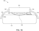
- FIG. 1B shows a side view of another example wrist-worn device 120.
- wrist-worn device 120 includes two band portions 122 and 123 coupled to two corresponding ends of a capsule 124.
- a bottom cover 126 of capsule 124 is configured to rest on a portion of a wrist 121 of a wearer.
- FIG. 1B illustrates possible locations of pressure sensors that may be included in wrist-worn device 120 configured to sense a pressure of bottom cover 126 to wrist 121.
- pressure sensors 128 and/or 130 may be positioned on sides of capsule 124 proximate to where band portion 122 or band portion 123 is coupled.
- pressure sensors 132 and/or 134 may be positioned proximate to where bottom cover 126 is affixed to a bottom portion of capsule 124. It should be noted that although four pressure sensors are depicted in FIG. 1B , this is merely exemplary, and, in some implementations, any suitable number of pressure sensors other than what is shown in FIG. 1B may be used (e.g., one, two, three, five, six, ten, or the like).
- Multiple (e.g., two, three, four, five, six, etc.) pressure sensors may be disposed proximate to a bottom cover of a wrist-worn device such that the pressure sensors are configured to detect variations in pressure across an X-Y plane corresponding to the bottom cover of the wrist-worn device.
- the variations in pressure across the X-Y plane may be used to detect a tilt of a capsule of the wrist-worn device relative to a body (e.g., a wrist surface) of the wearer.
- the variations in pressure across the X-Y plane may detect that the capsule is tilted to one side (e.g., due to the wrist-worn device being too big or too small for the wearer).
- variations in pressure across the X-Y plane may be used to detect where on a top surface (e.g., a display) of the capsule the wearer is pressing or moving a finger.
- Such pressure variations may be used as user input, for example, on a user interface (e.g., to scroll in a user interface presented on the display, to adjust a volume of audio content being presented by a user device paired to the wrist-worn device, or the like).
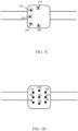
- FIGS. 1C and 1D show diagrams of example wrist-worn devices on which multiple pressure sensors have been disposed proximate to the bottom cover.
- pressure sensors 132, 134, 136, 138, and 140 are each affixed to a printed circuit board (PCB), each of which is disposed in a different location proximate to the bottom cover.
- PCB printed circuit board
- pressure sensors 152, 154, 156, 158, 160, 162, 164, 166, and 168 are disposed on a common PCB which is in turn disposed proximate to the bottom cover.
- the common PCB may additionally include other sensors and/or one or more processors which may be used for performing physiological measurements, and/or for any other suitable purposes.
- a pressure sensor may be a strain gauge type sensor.
- a strain gauge type sensor may detect bending due to pressure of a bottom cover of the wrist-worn device on a body portion of the wearer.
- a strain gauge sensor positioned proximate to the bottom cover may detect a bending or a deflection of the bottom cover of the wrist-worn device.
- a strain gauge sensor positioned proximate to a side of a capsule of the wrist-worn device may detect a bending or deflection of the side of the capsule, due to, e.g., the band of the wrist-worn device pulling on the side of the capsule.
- a strain gauge type sensor may be affixed to a surface of which the strain gauge type sensor detects deflection or bending.
- FIG. 1E is a schematic diagram that illustrates use of a strain gauge type sensor in accordance with the invention.
- a strain gauge sensor 152 is affixed via an adhesive layer 154 to a touch surface 156.
- touch surface 156 may correspond to a bottom cover of a wrist-worn device.
- strain gauge sensor 152 may be affixed to a first side of touch surface 156 (e.g., in an interior portion of a capsule of the wrist-worn device), and a second (e.g., opposing) side of touch surface 156 may be configured to be in contact with a body portion of the wearer (e.g., a wrist of the wearer).
- a strain gauge sensor may be affixed to a surface of which no side is configured to be in contact with the wearer.
- strain gauge sensor 152 may be affixed to a side portion of a capsule, where the opposing end from where strain gauge sensor 152 is affixed corresponds to an end on which a band is configured to be coupled.
- a pressure sensor may be a compression force sensor.
- a compression force sensor may be positioned between two surfaces and may be configured to detect a compression force between the two surfaces.
- a compression force sensor may be positioned between a bottom cover of a wrist-worn device and another surface of the wrist-worn device (e.g., a PCB surface within an interior of a capsule of the wrist-worn device) such that the signal produced by the compression force sensor is directly proportional to a force of the bottom cover of the wrist-worn device on a body portion (e.g., a wrist) of the wearer.
- FIG. 1F is a schematic diagram that illustrates use of a compression force sensor in accordance with some embodiments.
- a pressure sensor 162 may be affixed to a rubber element 164, which may in turn be affixed via adhesive 166 to a touch surface 168.
- touch surface 168 may correspond to a bottom cover of the wrist-worn device.
- adhesive 166 may be on a first side of touch surface 168 (e.g., in an interior portion of a capsule of the wrist-worn device), and a second (e.g., opposing) side of touch surface 168 may be configured to be in contact with a body portion of the wearer (e.g., a wrist of the wearer).
- Rubber element 164 may serve to thermally and/or mechanically isolate pressure sensor 162 such that pressure sensor 162 is not affected by thermal variations on the portion of touch surface 168 that is physically in contact with the skin of the wearer.
- an opposing side of pressure sensor 162 is affixed to an opposing surface 170.
- Opposing surface 170 may be positioned within an interior of a capsule of the wrist-worn device.
- opposing surface 170 may be a surface of a PCB within the capsule.
- Wrist-worn devices such as fitness trackers or smart watches, frequently measure physiological characteristics of a wearer. These physiological characteristics may include heart rate, oxygen saturation, blood pressure, or the like. These physiological characteristics may be determined using measurements from one or more sensors on-board the wrist-worn device, such as one or more light emitters, one or more light detectors, one or more accelerometers, one or more gyroscopes, etc.
- PPG is an example of a technique that may be used to determine heart rate, oxygen saturation, blood pressure, etc.
- light is emitted toward skin of the wearer, and the light is then reflected from the skin and/or from various internal body regions (e.g., blood vessels, blood cells, bone, etc.). The reflected light is then captured by one or more light detectors of the wrist-worn device, and characteristics of the reflected light, such as changes in absorption over different wavelengths of light, may be used to determine heart rate, oxygen saturation, blood pressure, etc.
- FIG. 2 illustrates an example of optimal band tightness for physiological measurements that rely on detecting reflected light (e.g., using PPG) in accordance with the invention.
- transmitted light may not reach blood vessels in the tissue of the wearer, and accordingly, reflected light may not reach a light detector within the wrist-worn device. This may lead to poor PPG data, and, in turn, poor physiological measurements determined based on the PPG data.
- transmitted light from emitters of the wrist-worn device may pass through the skin of the wearer and reflect off of blood vessels carrying both venous blood and arterial blood.
- PPG-based physiological measurements may be possible, but, because measurements that include absorption of venous (e.g., non-oxygenated) blood may lead to less reliable results, band tightness that results in the wrist-worn device being merely in contact with the skin of the wearer may yield sub-optimal (e.g., inaccurate) results.
- band tightness that results in the wrist-worn device being merely in contact with the skin of the wearer may yield sub-optimal (e.g., inaccurate) results.
- the band tightness is optimal, venous blood may be occluded, while allowing arterial blood to not be occluded. In this instance, by suppressing absorption measurements of venous blood, PPG-based measurements may be the most accurate.
- both venous blood and arterial blood may be occluded.
- PPG-based measurements may be less accurate than in an instance in which the band is less tight.
- an optimal contact pressure of the wrist-worn device to the wrist of the wearer there may be an optimal contact pressure of the wrist-worn device to the wrist of the wearer (and accordingly, an optimal band tightness) for physiological measurements.
- FIG. 2 illustrates an example of optimal contact pressure in an instance in which physiological measurements are made using characteristics of measured reflected light
- an optimal band tightness may exist for physiological measurements that are made using other techniques, such as based on accelerometers, or the like.
- an optimal contact pressure may vary based on multiple factors, such as the type of sensors being used, the type of physiological measurement being performed, an ambient temperature, whether the wearer is in motion (e.g., walking, running, etc.), whether the wearer is sleeping, or the like.
- a current contact pressure of a wrist-worn device to a wrist of a wearer may be determined using one or more pressure sensors of the wrist-worn device.
- the current contact pressure may be compared to a target contact pressure.
- the target contact pressure may be different for different types of physiological measurements, for different people, at different ambient temperatures or humidity levels, during different activities (e.g., sleeping, exercising, working at a computer, etc.), and/or vary based on any other criteria.
- target contact pressure may be determined for an individual based on a calibration process performed while the individual is wearing the wrist-worn device. Additionally or alternatively, the target contact pressure may be determined based on data collected from multiple users.
- instructions may be provided to the wearer to alter a tightness of the wrist-worn device to achieve the target contact pressure. For example, instructions may be provided to tighten the band of the wrist-worn device (e.g., by a suggested number of notches), loosen the band of the wrist-worn device (e.g., by a suggested number of notches), or the like.
- FIG. 3 is a flowchart of an example process 300 to provide instructions to alter a tightness of a wrist-worn device in accordance with the invention.
- blocks of process 300 may be performed by one or more processors.
- the one or more processors may be on-board the wrist-worn device. Additionally or alternatively, the one or more processors may be on a user device (e.g., a mobile phone, a tablet computer, or the like) that is paired with the wrist-worn device, on a server device, or any other suitable device.
- blocks of process 300 may be executed in an order other than what is shown in FIG. 3 .
- two or more blocks of process 300 may be performed substantially in parallel.
- one or more blocks of process 300 may be omitted.
- Process 300 can begin at 302 by obtaining sensor data from one or more pressure sensors disposed in and/or on a wrist-worn device.
- the one or more pressure sensors may be disposed proximate to a back cover of the wrist-worn device, proximate to a side of a capsule of the wrist-worn device, proximate to a band of the wrist-worn device, and/or in any other suitable location(s).
- the one or more pressure sensors may be strain gauge type sensors, compression force sensors, and/or a combination of strain gauge sensors and compression force sensors.
- the sensor data may be obtained by a processor, which may be on-board the wrist-worn device or remote from the wrist-worn device.
- the sensor data may be transmitted from the wrist-worn device to a user device paired with the wrist-worn device for subsequent analysis and processing.
- the sensor data may be transmitted from the wrist-worn device to a server device for subsequent analysis and processing.
- process 300 can determine a contact pressure of the wrist-worn device to a wrist of the wearer based on the sensor data. For example, in instances in which the one or more pressure sensors include a strain gauge type sensor, process 300 can determine the contact pressure based on an amount of deflection of a surface the strain gauge type sensor is affixed to. As another example, in instances in which the one or more pressure sensors include a compression force type sensor, process 300 can determine the contact pressure based on an amount of compression experienced by the compression force sensor. In some implementations, process 300 may determine contact pressure by providing the sensor data to a look up table or algorithm (e.g., one or more mathematical functions) that translate the sensor data to a contact pressure measurement.
- a look up table or algorithm e.g., one or more mathematical functions
- process 300 may combine data from the two or more pressure sensors. For example, in some implementations, process 300 may determine an aggregate contact pressure by averaging or combining the data from the two or more pressure sensors. In some implementations, process 300 may aggregate sensor data from two or more pressure sensors responsive to the two or more pressure sensors being of the same sensor type (e.g., strain gauge sensors or compression force sensors). As another example, in some implementations, process 300 may utilize the sensor data from the two or more pressure sensors to determine whether the capsule of the wrist-worn device is tilted in a particular direction.
- process 300 may utilize the sensor data from the two or more pressure sensors to determine whether the capsule of the wrist-worn device is tilted in a particular direction.
- process 300 may determine that the capsule of the wrist-worn device is tilted toward the pressure sensor providing increased contact pressure measurements.
- process 300 can identify a target contact pressure of the wrist-worn device.
- the target contact pressure may be identified based on a physiological measurement that is to be performed, types of sensors to be used for physiological measurements, a current activity state of the wearer, a current ambient temperature or humidity, and/or any suitable combination of factors.
- types of physiological measurements that may be considered when identifying a target contact pressure include heart rate, oxygen saturation, blood pressure, EMG sensing, and/or body temperature.
- types of sensors to be used for physiological measurements include light emitters, light detectors, accelerometers, gyroscopes, surface EMG electrodes, or the like.
- a wavelength of light that is to be emitted and/or captured in a reflection may be considered when determining the target contact pressure.
- activity states may include walking, running, sitting, typing, sleeping, or the like.
- Process 300 may determine the target contact pressure in a manner that is specific to the wearer of the wrist-worn device.
- a calibration technique may have previously been performed for the wearer of the wrist-worn device to determine target contact pressures for different physiological measurements, under different activity states, at different ambient temperatures or humidities, or the like.
- the calibration technique may involve performing one or more physiological measurements (e.g., measuring heart rate, oxygen saturation, or the like) with varying band tightness.
- the calibration technique may involve instructing the user to adjust the band to their preferred tightness, performing a physiological measurement, instructing the user to adjust the band to tighter and/or looser states, and re-performing the physiological measurement.
- the optimal band tightness for the physiological measurement performed may be identified as the band tightness corresponding to the contact pressure under which the physiological measurement satisfies various criteria (e.g., variance in a sequence of physiological measurements being below a predetermined threshold, or the like).
- the calibration technique may be repeated for the wearer under different ambient temperature conditions.
- process 300 may determine the target contact pressure based on data collected from multiple users other than the wearer of the wrist-worn device. For example, physiological measurements may be collected from wrist-worn devices of the multiple users and stored in connection with other data indicating, e.g., the contact pressure of the wrist-worn device at the time the physiological measurement was made, the ambient temperature and/or humidity at a time the physiological measurement was made, the activity the wearer was engaged in at the time the physiological measurement was made, or the like.
- the physiological measurements may be scored or evaluated for quality based on various criteria such as a likelihood the physiological measurement is accurate (e.g., based on whether the physiological measurement is a plausible value), variance of a sequence of physiological measurements collected in a relatively short duration of time (e.g., within five seconds, within ten seconds, within thirty seconds, within a minute, or the like), and/or any other criteria.
- the target contact pressure may be identified as one that is associated with higher-scored physiological measurements from the multiple users. In other words, the target contact pressure may be identified as one that is more likely to yield higher quality physiological measurements.
- One or more machine learning models may be trained using the data from the multiple users, and the target contact pressure may be obtained by providing input indicative of one or more physiological measurements to be performed, types of sensors to be used to perform the one or more physiological measurements, a current activity state of the wearer, and/or ambient weather conditions, where the target contact pressure is an output of the machine learning model.
- process 300 may provide instructions to the wearer to adjust the wrist-worn device to achieve the identified target contact pressure. For example, in an instance in which the contact pressure detected at block 304 is greater than the target contact pressure identified at block 306, process 300 may present instructions that instruct the user to loosen a band of the wrist-worn device to decrease the current contact pressure. Conversely, in an instance in which the contact pressure detected at block 304 is less than the target contact pressure identified at block 306, process 300 may present instructions that instruct the user to tighten a band of the wrist-worn device to increase the contact pressure.
- the instructions may include an indication of the magnitude of the adjustment. For example, the instructions may indicate a number of notches the band is to be loosened or tightened.
- the instructions may state "increase the band tightness by one notch," or the like.
- the magnitude of the adjustment may be determined based on a degree to which the current contact pressure differs from the identified target contact pressure, with larger adjustments being indicated for larger differences between the current contact pressure and the target contact pressure, and vice versa.
- the instructions may be presented on a display of the wrist-worn device. Additionally or alternatively, the instructions may be presented on a display of a user device paired with the wrist-worn device, such as a display of a paired mobile phone or tablet computer. In some implementations, the instructions may be presented in connection with any suitable type of alert, such as haptic feedback, an audible tone, or the like.
- one or more changes may be made while performing physiological measurements based on a current contact pressure of the wrist-worn device to the wrist of the wearer.
- the one or more changes made while performing physiological measurements may allow for closed-loop control of physiological measurements, thereby causing the physiological measurements to be more accurate.
- the one or more changes may include changes to hardware.
- the one or more changes may include increased current of an LED used to emit light toward tissue of the wearer, such as that used in connection with PPG-based measurements.
- the one or more changes may include changes to a manner in which physiological measurements are determined.
- the one or more changes may include integrating the collected sensor data over a longer than usual duration of time to, for example, increase signal to noise ratio.
- the one or more changes may include augmenting sensor data used to determine the physiological measurements with other data, such as body temperature data, motion sensor data, or the like, which may improve an accuracy of the physiological measurements.
- physiological measurements may be reported in an altered manner, for example, with an indication that the physiological measurements may not be accurate due to inappropriate band tightness of the wrist-worn device.
- physiological measurements may be discarded (e.g., not stored and/or not provided to the wearer) responsive to the current contact pressure deviating from the target contact pressure by more than the threshold amount.
- FIG. 4 is a flowchart of an example process 400 for closed-loop control of physiological measurements based on contact pressure of a wrist-worn device to a wrist of a wearer in accordance with the invention.
- process 400 may be performed by one or more processors.
- the one or more processors may be on-board the wrist-worn device. Additionally or alternatively, at least one of the one or more processors may be on a user device (e.g., a mobile phone, a tablet computer, or the like) paired with the wrist-worn device, a server, etc.
- blocks of process 400 may be performed in an order other than what is shown in FIG. 4 .
- two or more blocks of process 400 may be performed substantially in parallel.
- one or more blocks of process 400 may be omitted.
- Process 400 can begin at 402 by obtaining sensor data from one or more pressure sensors disposed in and/or on a wrist-worn device. Similar to what is described above in connection with block 302 of FIG. 3 , the one or more pressure sensors may be disposed at any suitable locations of the wrist-worn device, and the one or more pressure sensors may be strain gauge type sensors, compression force type sensors, or any combination thereof.
- process 400 can determine a contact pressure of the wrist-worn device to a wrist of the wearer based on the sensor data. Similar to what is described above in connection with block 304 of FIG. 3 , the contact pressure may be determined using the sensor data by, for example, providing the sensor data to an algorithm or look-up table that translates the sensor data to a corresponding contact pressure. Additionally or alternatively, as described above in connection with block 304 of FIG. 3 , data from multiple pressure sensors may be combined to determine an aggregate contact pressure and/or to determine a tilt of the capsule of the wrist-worn device relative to the wrist of the wearer.
- process 400 can identify a target contact pressure of the wrist-worn device for a type of physiological measurement to be made using sensors of the wrist-worn device.
- types of physiological measurements include heart rate, oxygen saturation, blood pressure, respiration rate, muscle activity measurements (e.g., EMG measurements), and/or body temperature.
- process 400 may identify the target contact pressure for the type of physiological measurement by accessing a look-up table that specifies a target contact pressure for the particular type of physiological measurement. Additionally or alternatively, process 400 may identify the target contact pressure by providing the type of physiological measurement in connection with any other relevant information (e.g., current ambient weather conditions, current activity state of the wearer, etc.) to a machine learning model that generates the target contact pressure as an output.
- any other relevant information e.g., current ambient weather conditions, current activity state of the wearer, etc.
- a look-up table, a trained machine learning model, and/or any other source of the target contact pressure may be specific to the wearer of the wrist-worn device.
- the look-up table, the trained machine learning model, or the like may be generated based on a calibration routine performed with the wearer of the wrist-worn device, as described above in connection with block 306 of FIG. 3 .
- process 400 can determine at least one change to be made when performing the physiological measurement based on a difference between the contact pressure determined at block 404 and the target contact pressure identified at block 406.
- the at least one change made depend on a direction of the difference (e.g., whether the contact pressure is greater than or less than the target contact pressure), a degree of the difference, and/or the type of physiological measurement.
- the at least one change may include changes to a light emitter used to emit light toward the tissue of the wearer.
- the at least one change may include a change in LED current (e.g., an increase in LED current) to cause the light emitted toward the tissue of the wearer to be brighter/more intense, which may ameliorate negative effects of a contact pressure that differs from the target contact pressure.
- the degree of change in LED current may correspond to a degree to which the contact pressure differs from the target contact pressure.
- LED current may be changed by a greater amount in instances in which the contact pressure differs from the target contact pressure by a greater amount, and vice versa.
- the LED current may be increased to overcome negative effects from a back cover of the wrist-worn device that is poorly in contact with the wrist of the wearer (e.g., as shown in and described above in connection with panel 204 of FIG. 2 ).
- the LED current may be decreased to overcome negative effects from a too-tight wrist-worn device (e.g., as shown in and described above in connection with panel 208 of FIG. 2 ).
- the at least one change can include integrating sensor data used to perform the physiological measurement over an increased time duration relative to the typical integration time duration.
- noise in the sensor data may be averaged out, thereby causing increased signal to noise ratio in the sensor data used to determine the physiological measurement.
- the time duration may be increased in cases where the contact pressure is greater than the target contact pressure and in instances in which the contact pressure is less than the target contact pressure.
- the integration time may be changed based on the type of physiological measurement to be performed.
- the integration time may be changed by a first amount in instances in which the physiological measurement corresponds to a first type of physiological measurement (e.g., heart rate), and by a second amount in instances in which the physiological measurement corresponds to a second type of physiological measurement (e.g., oxygen saturation).
- a first type of physiological measurement e.g., heart rate
- a second amount in instances in which the physiological measurement corresponds to a second type of physiological measurement (e.g., oxygen saturation).
- the at least one change can include considering other data when determining the physiological measurement.
- the other data may include motion data (e.g., obtained from one or more accelerometers and/or gyroscopes of the wrist-worn device) and/or body temperature data (e.g., obtained from one or more temperature sensors of the wrist-worn device).
- motion data e.g., obtained from one or more accelerometers and/or gyroscopes of the wrist-worn device
- body temperature data e.g., obtained from one or more temperature sensors of the wrist-worn device.
- motion data may be considered when determining the heart rate. This may compensate for effects from, e.g., a too-loose band and the wrist-worn device slipping on a wrist of the wearer during exercise.
- motion data may be considered when determining the EMG activity. This may compensate for effects from, e.g., a too loose or too tight band precluding acquisition of robust EMG signals during hand, finger, or wrist motion.
- process 400 can perform the physiological measurements while implementing the at least one change.
- process 400 can cause light to be emitted toward a tissue of the wearer, obtain measurements indicating light reflected from the tissue of the wearer, and determine the physiological measurement based on the obtained measurements while implementing the at least one change (e.g., a change in the LED current of the light emitter, integrating outputs of the light detector over a longer time period, considering motion sensor data, considering temperature sensor data, etc.).
- process 400 can receive outputs from one or more EMG electrodes and determine EMG activity of one or more muscles while implementing the at least one change (e.g., integrating outputs of the EMG electrodes over a longer time period, considering motion sensor data, considering temperature sensor data, etc.).
- the other data e.g., motion data, temperature data, or the like
- the at least one change made when performing the physiological measurement may be maintained during subsequent physiological measurements.
- the at least one change may be maintained until the contact pressure changes (e.g., to be closer to the target contact pressure).
- the at least one change may be maintained until at least one other condition changes, such as a change in the activity state of the wearer, a change in the ambient weather conditions, or the like.
- a determination of whether to continue the at least one change made when performing the physiological measurement may be made.
- the increased LED current may be used during a current activity state of the user (e.g., during exercise), and use of the increased LED current during PPG-based measurements may be re-evaluated responsive to detecting a change in the current activity state (e.g., during rest).
- contact pressure information may be utilized to determine at least one physiological measurement.
- the contact pressure information may indicate pulsatile pressure changes imparted to the back cover of the wrist-worn device by pulsatile changes in a user's artery under the wrist-worn device (e.g., the radial artery or the ulnar artery).
- blood ejected from the aorta of the heart may cause an upward then subsequent downward pulsatile motion of distal arteries (e.g., the radial artery and/or the ulnar artery in the wrist), where the pulsatile motion of the artery may be transferred to the back cover of the wrist-worn device and detected and/or characterized by force sensors proximate the back cover.
- the contact pressure information may be considered ballistocardiogram information.
- the contact pressure information may be used to determine heart rate.
- the contact pressure information may correspond to ballistocardiograph data.
- a heart rate may be determined from the ballistocardiograph data based on, e.g., a periodicity in the ballistocardiograph data.
- a heart rate may be determined to be the inverse of a period of a ballistocardiogram signal.
- Periodicity information may be determined using spectral analysis techniques or the like.
- the contact pressure information may be used to determine other physiological measurements, such as blood pressure or oxygen saturation, in conjunction with PPG data.
- the contact pressure information may be used to calibrate the physiological measurement determined using PPG data.
- the contact pressure information may be used to scale a blood pressure measurement from a relative pressure determined using the PPG data to an absolute blood pressure.
- FIG. 5 is a flowchart of an example process 500 for determining physiological measurements using contact pressure information.
- blocks of process 500 may be implemented using one or more processors or controllers of a wrist-worn device.
- two or more blocks of process 500 may be executed substantially in parallel.
- one or more blocks of process 500 may be omitted.
- blocks of process 500 may be executed in an order other than what is shown in FIG. 5 .
- Process 500 can begin at 502 by obtaining sensor data from one or more pressure sensors disposed in and/or on a wrist-worn device. Similar to what is described above in connection with block 302 of FIG. 3 , the one or more pressure sensors may be disposed at any suitable locations of the wrist-worn device, and the one or more pressure sensors may be strain gauge type sensors, compression force type sensors, or any combination thereof.
- process 500 can determine pressure information indicative of a contact pressure of the wrist-worn device with respect to the wrist of the wearer. Similar to what is described above in connection with block 304 of FIG. 3 , the contact pressure may be determined using the sensor data by, for example, providing the sensor data to an algorithm or look-up table that translates the sensor data to a corresponding contact pressure. Additionally or alternatively, as described above in connection with block 304 of FIG. 3 , data from multiple pressure sensors may be combined to determine an aggregate contact pressure and/or to determine a tilt of the capsule of the wrist-worn device relative to the wrist of the wearer.
- process 500 can determine at least one physiological measurement using at least the pressure information.
- physiological measurements include a heart rate, a blood pressure, an oxygen saturation, a heart rate variability, or the like.
- the pressure information may represent a ballistocardiogram.
- a heart rate may be determined using periodicity information of the ballistocardiogram, e.g., by determining the heart rate as the inverse of the period of the heart rate signal represented in the ballistocardiogram.
- information derived from the pressure information may be used to determine the physiological measurement.
- cardiac cycle reference points or biomarkers may be identified in the ballistocardiogram. Timing information associated with these biomarkers may then be used to determine or calibrate various physiological measurements, such as a blood pressure, oxygen saturation, etc. Examples of biomarkers that may be identified in the ballistocardiogram include the diastolic point, the dicrotic notch, or the like.
- timing information associated with a biomarker identified in the ballistocardiogram (e.g., obtained from the pressure information) may be used in conjunction with a PPG signal to determine a physiological measurement.
- the PPG signal may be annotated with the identified biomarkers, and the physiological measurement (e.g., blood pressure, oxygen saturation, etc.) may be identified based on the annotated PPG signal.
- the pressure information may be used to calibrate a relative blood pressure determined using a PPG signal.
- a PPG signal may be used to determine a relative blood pressure
- the pressure information may be used to modify the relative blood pressure measurement obtained using PPG to units of pressure (e.g., mmHG).
- the pressure information may be used to calibrate or scale a relative blood pressure obtained using PPG to an absolute blood pressure in units of mmHG.
- the PPG signal may be obtained from a device other than the wrist-worn device.
- the other device may be a user device that is paired with or otherwise associated with (e.g., via a BLUETOOTH connection or other wireless communication channel) with the wrist-worn device.
- other devices include: smart glasses, a virtual reality (VR) or augmented reality (AR) headset, a mobile phone, a wearable ring, etc.
- the PPG signal may be obtained by utilizing a light emitter and/or a light detector disposed in a frame of the glasses/headset such that the light is emitted toward a portion of the wearer's forehead or the side of their head, toward the user's ear, etc.
- An artificial reality system such as a head-mounted display (HMD) or heads-up display (HUD) system, generally includes a display configured to present artificial images that depict objects in a virtual environment.
- the display may present virtual objects or combine images of real objects with virtual objects, as in virtual reality (VR), augmented reality (AR), or mixed reality (MR) applications.
- VR virtual reality
- AR augmented reality
- MR mixed reality
- a user may view both displayed images of virtual objects (e.g., computer-generated images (CGIs)) and the surrounding environment by, for example, seeing through transparent display glasses or lenses (often referred to as optical see-through) or viewing displayed images of the surrounding environment captured by a camera (often referred to as video see-through).
- virtual objects e.g., computer-generated images (CGIs)
- optical see-through transparent display glasses or lenses
- video see-through e.g., a camera
- the artificial images may be presented to users using an LED-based display subsystem.
- a wearable computer such as a smart watch, a fitness tracker, a HMD, or the like.
- a wearable computer may include one or more light emitters and/or one or more light sensors incorporated into a portion of an enclosure of the wearable computer such that light can be emitted toward a tissue of a wearer of the wearable computer that is proximate to or touching the portion of the enclosure of the wearable computer.
- Example locations of such a portion of an enclosure of a wearable computer may include a portion configured to be proximate to an ear of the wearer (e.g., proximate to a superior tragus, proximate to a superior auricular, proximate to a posterior auricular, proximate to an inferior auricular, or the like), proximate to a forehead of the wearer, proximate to a wrist of the wearer, proximate to a finger tip of the wearer, proximate to a base of a finger of a wearer, proximate to a toe tip of a wearer, or the like.
- an ear of the wearer e.g., proximate to a superior tragus, proximate to a superior auricular, proximate to a posterior auricular, proximate to an inferior auricular, or the like
- FIG. 6 is a simplified block diagram of an example of a computing system 600 for implementing some of the examples described herein.
- computing system may be used to implement a user device (e.g., a mobile phone, a tablet computer, a wrist-worn device, etc.) that implements the blocks of process 300 and/or process 400 shown in and described above in connection with FIGS. 3 and 4 .
- computing system 600 may include one or more processor(s) 610 and a memory 620.
- Processor(s) 610 may be configured to execute instructions for performing operations at a number of components, and can be, for example, a general-purpose processor or microprocessor suitable for implementation within a portable electronic device.
- Processor(s) 610 may be communicatively coupled with a plurality of components within computing system 600. To realize this communicative coupling, processor(s) 610 may communicate with the other illustrated components across a bus 640.
- Bus 640 may be any subsystem adapted to transfer data within computing system 600.
- Bus 640 may include a plurality of computer buses and additional circuitry to transfer data.
- Memory 620 may be coupled to processor(s) 610. Memory 620 may offer both short-term and long-term storage and may be divided into several units. Memory 620 may be volatile, such as static random access memory (SRAM) and/or dynamic random access memory (DRAM) and/or non-volatile, such as read-only memory (ROM), flash memory, and the like. Furthermore, memory 620 may include removable storage devices, such as secure digital (SD) cards. Memory 620 may provide storage of computer-readable instructions, data structures, program modules, and other data for computing system 600. Memory 620 may be distributed into different hardware modules. A set of instructions and/or code might be stored on memory 620.
- SRAM static random access memory
- DRAM dynamic random access memory
- ROM read-only memory
- SD secure digital
- the instructions might take the form of executable code that may be executable by computing system 600, and/or might take the form of source and/or installable code, which, upon compilation and/or installation on computing system 600 (e.g., using any of a variety of generally available compilers, installation programs, compression/decompression utilities, etc.), may take the form of executable code.
- Memory 620 may store a plurality of application modules 622 through 624, which may include any number of applications. Examples of applications may include gaming applications, conferencing applications, video playback applications, or other suitable applications. The applications may include a depth sensing function or eye tracking function. Application modules 622-624 may include particular instructions to be executed by processor(s) 610. Certain applications or parts of application modules 622-624 may be executable by other hardware modules 680. In certain embodiments, memory 620 may additionally include secure memory, which may include additional security controls to prevent copying or other unauthorized access to secure information.
- Memory 620 may include an operating system 625 loaded therein.
- Operating system 625 may be operable to initiate the execution of the instructions provided by application modules 622-624 and/or manage other hardware modules 680 as well as interfaces with a wireless communication subsystem 630 which may include one or more wireless transceivers.
- Operating system 625 may be adapted to perform other operations across the components of computing system 600 including threading, resource management, data storage control and other similar functionality.
- Wireless communication subsystem 630 may include, for example, an infrared communication device, a wireless communication device and/or chipset (such as a Bluetooth ® device, an IEEE 802.11 device, a Wi-Fi device, a WiMax device, cellular communication facilities, etc.), and/or similar communication interfaces.
- Computing system 600 may include one or more antennas 634 for wireless communication as part of wireless communication subsystem 630 or as a separate component coupled to any portion of the system.
- wireless communication subsystem 630 may include separate transceivers to communicate with base transceiver stations and other wireless devices and access points, which may include communicating with different data networks and/or network types, such as wireless wide-area networks (WWANs), wireless local area networks (WLANs), or wireless personal area networks (WPANs).
- WWAN may be, for example, a WiMax (IEEE 802.15) network.
- WLAN may be, for example, an IEEE 802.11x network.
- a WPAN may be, for example, a Bluetooth network, an IEEE 802.5x, or some other types of network.
- the techniques described herein may also be used for any combination of WWAN, WLAN, and/or WPAN.
- Wireless communications subsystem 630 may permit data to be exchanged with a network, other computer systems, and/or any other devices described herein.
- Wireless communication subsystem 630 may include a means for transmitting or receiving data, such as identifiers of HMD devices, position data, a geographic map, a heat map, photos, or videos, using antenna(s) 634 and wireless link(s) 632.
- Wireless communication subsystem 630, processor(s) 610, and memory 620 may together comprise at least a part of one or more of a means for performing some functions disclosed herein.
- Examples of computing system 600 may also include one or more sensors 690.
- Sensor(s) 690 may include, for example, an image sensor, an accelerometer, a pressure sensor, a temperature sensor, a proximity sensor, a magnetometer, a gyroscope, an inertial sensor (e.g., a module that combines an accelerometer and a gyroscope), an ambient light sensor, or any other similar module operable to provide sensory output and/or receive sensory input, such as a depth sensor or a position sensor.
- sensor(s) 690 may include one or more inertial measurement units (IMUs) and/or one or more position sensors.
- IMUs inertial measurement units
- An IMU may generate calibration data indicating an estimated position of a device, based on measurement signals received from one or more of the position sensors.
- a position sensor may generate one or more measurement signals in response to motion of a device. Examples of the position sensors may include, but are not limited to, one or more accelerometers, one or more gyroscopes, one or more magnetometers, another suitable type of sensor that detects motion, a type of sensor used for error correction of the IMU, or some combination thereof.
- the position sensors may be located external to the IMU, internal to the IMU, or some combination thereof. At least some sensors may use a structured light pattern for sensing.
- Computing system 600 may include a display module 660.
- Display module 660 may be a near-eye display, and may graphically present information, such as images, videos, and various instructions, from computing system 600 to a user. Such information may be derived from one or more application modules 622-624, virtual reality engine 626, one or more other hardware modules 680, a combination thereof, or any other suitable means for resolving graphical content for the user (e.g., by operating system 625).
- Display module 660 may use liquid crystal display (LCD) technology, light-emitting diode (LED) technology (including, for example, OLED, ILED, mLED, AMOLED, TOLED, etc.), light emitting polymer display (LPD) technology, or some other display technology.
- LCD liquid crystal display
- LED light-emitting diode
- LPD light emitting polymer display
- Computing system 600 may include a user input/output module 670.
- User input/output module 670 may allow a user to send action requests to computing system 600.
- An action request may be a request to perform a particular action.
- an action request may be to start or end an application or to perform a particular action within the application.
- User input/output module 670 may include one or more input devices.
- Example input devices may include a touchscreen, a touch pad, microphone(s), button(s), dial(s), switch(es), a keyboard, a mouse, a game controller, or any other suitable device for receiving action requests and communicating the received action requests to computing system 600.
- User input/output module 670 may provide haptic feedback to the user in accordance with instructions received from computing system 600. For example, the haptic feedback may be provided when an action request is received or has been performed.
- Computing system 600 may include a camera 650 that may be used to take photos or videos.
- Camera 650 may be configured to take photos or videos of the user.
- Camera 650 may also be used to take photos or videos of the environment, for example, for VR, AR, or MR applications.
- Camera 650 may include, for example, a complementary metal-oxide-semiconductor (CMOS) image sensor with a few millions or tens of millions of pixels.
- CMOS complementary metal-oxide-semiconductor
- camera 650 may include two or more cameras that may be used to capture 3-D images.
- Computing system 600 may include a plurality of other hardware modules 680.
- Each of other hardware modules 680 may be a physical module within computing system 600. While each of other hardware modules 680 may be permanently configured as a structure, some of other hardware modules 680 may be temporarily configured to perform specific functions or temporarily activated. Examples of other hardware modules 680 may include, for example, an audio output and/or input module (e.g ., a microphone or speaker), a near field communication (NFC) module, a rechargeable battery, a battery management system, a wired/wireless battery charging system, etc. In some embodiments, one or more functions of other hardware modules 680 may be implemented in software.
- Memory 620 of computing system 600 may also store a virtual reality engine 626.
- Virtual reality engine 626 may execute applications within computing system 600 and receive position information, acceleration information, velocity information, predicted future positions, or some combination thereof from the various sensors. The information received by virtual reality engine 626 may be used for producing a signal (e.g ., display instructions) to display module 660. For example, if the received information indicates that the user has looked to the left, virtual reality engine 626 may generate content that mirrors the user's movement in a virtual environment. Additionally, virtual reality engine 626 may perform an action within an application in response to an action request received from user input/output module 670 and provide feedback to the user. The provided feedback may be visual, audible, or haptic feedback.
- processor(s) 610 may include one or more GPUs that may execute virtual reality engine 626.
- the above-described hardware and modules may be implemented on a single device or on multiple devices that can communicate with one another using wired or wireless connections.
- some components or modules such as GPUs, virtual reality engine 626, and applications (e.g ., tracking application), may be implemented on two or more paired or connected devices.
- computing system 600 may be modified to include other system environments, such as an AR system environment and/or an MR environment.
- FIG. 7 is a simplified block diagram of an example of a computing system 700 that may be implemented in connection with a server.
- computing system 700 may be used to implement a server that generates a trained machine learning model that identifies target contact pressures, stores data related to contact pressures of wrist-worn devices of multiple users, or the like.
- computing system 700 may include one or more processor(s) 710 and a memory 720.
- Processor(s) 710 may be configured to execute instructions for performing operations at a number of components, and can be, for example, a general-purpose processor or microprocessor suitable for implementation within a portable electronic device.
- Processor(s) 710 may be communicatively coupled with a plurality of components within computing system 700. To realize this communicative coupling, processor(s) 710 may communicate with the other illustrated components across a bus 740.
- Bus 740 may be any subsystem adapted to transfer data within computing system 700.
- Bus 740 may include a plurality of computer buses and additional circuitry to transfer data.
- Processor(s) 710 may be configured to perform one or more blocks of process 400, as shown in and described above in connection with FIG. 4 , respectively.
- Memory 720 may be coupled to processor(s) 710. Memory 720 may offer both short-term and long-term storage and may be divided into several units. Memory 720 may be volatile, such as static random access memory (SRAM) and/or dynamic random access memory (DRAM) and/or non-volatile, such as read-only memory (ROM), flash memory, and the like. Furthermore, memory 720 may include removable storage devices, such as secure digital (SD) cards. Memory 720 may provide storage of computer-readable instructions, data structures, program modules, and other data for computing system 700. In some examples, memory 720 may be distributed into different hardware modules. A set of instructions and/or code might be stored on memory 720.
- SRAM static random access memory
- DRAM dynamic random access memory
- ROM read-only memory
- SD secure digital
- the instructions might take the form of executable code that may be executable by computing system 700, and/or might take the form of source and/or installable code, which, upon compilation and/or installation on computing system 700 (e.g., using any of a variety of generally available compilers, installation programs, compression/decompression utilities, etc.), may take the form of executable code.
- Memory 720 may store a plurality of application modules 722 through 724, which may include any number of applications. Examples of applications may include gaming applications, conferencing applications, video playback applications, or other suitable applications. Application modules 722-724 may include particular instructions to be executed by processor(s) 710. Certain applications or parts of application modules 722-724 may be executable by other hardware modules. Memory 720 may additionally include secure memory, which may include additional security controls to prevent copying or other unauthorized access to secure information.
- Memory 720 may include an operating system 725 loaded therein.
- Operating system 725 may be operable to initiate the execution of the instructions provided by application modules 722-724 and/or manage other hardware modules as well as interfaces with a wireless communication subsystem 730 which may include one or more wireless transceivers.
- Operating system 725 may be adapted to perform other operations across the components of computing system 700 including threading, resource management, data storage control and other similar functionality.
- Communication subsystem 730 may include, for example, an infrared communication device, a wireless communication device and/or chipset (such as a Bluetooth ® device, an IEEE 802.11 device, a Wi-Fi device, a WiMax device, cellular communication facilities, etc.), a wired communication interface, and/or similar communication interfaces.
- Computing system 700 may include one or more antennas 734 for wireless communication as part of wireless communication subsystem 730 or as a separate component coupled to any portion of the system.
- communication subsystem 730 may include separate transceivers to communicate with base transceiver stations and other wireless devices and access points, which may include communicating with different data networks and/or network types, such as wireless wide-area networks (WWANs), wireless local area networks (WLANs), or wireless personal area networks (WPANs).
- WWAN wireless wide-area networks
- WLAN wireless local area networks
- WPAN wireless personal area networks
- a WWAN may be, for example, a WiMax (IEEE 802.15) network.
- a WLAN may be, for example, an IEEE 802.11x network.
- a WPAN may be, for example, a Bluetooth network, an IEEE 802.6x, or some other types of network.
- the techniques described herein may also be used for any combination of WWAN, WLAN, and/or WPAN.
- Communications subsystem 730 may permit data to be exchanged with a network, other computer systems, and/or any other devices described herein.
- Communication subsystem 730 may include a means for transmitting or receiving data, using antenna(s) 734, wireless link(s) 732, or a wired link.
- Communication subsystem 730, processor(s) 710, and memory 720 may together comprise at least a part of one or more of a means for performing some functions disclosed herein.
- Computing system 700 may include one or more output device(s) 760 and/or one or more input device(s) 770.
- Output device(s) 770 and/or input device(s) 770 may be used to provide output information and/or receive input information.
- Embodiments disclosed herein may be used to implement components of an artificial reality system or may be implemented in conjunction with an artificial reality system.
- Artificial reality is a form of reality that has been adjusted in some manner before presentation to a user, which may include, for example, a virtual reality, an augmented reality, a mixed reality, a hybrid reality, or some combination and/or derivatives thereof.
- Artificial reality content may include completely generated content or generated content combined with captured ( e.g ., real-world) content.
- the artificial reality content may include video, audio, haptic feedback, or some combination thereof, and any of which may be presented in a single channel or in multiple channels (such as stereo video that produces a three-dimensional effect to the viewer).
- artificial reality may also be associated with applications, products, accessories, services, or some combination thereof, that are used to, for example, create content in an artificial reality and/or are otherwise used in (e.g., perform activities in) an artificial reality.
- the artificial reality system that provides the artificial reality content may be implemented on various platforms, including an HMD connected to a host computer system, a standalone HMD, a mobile device or computing system, or any other hardware platform capable of providing artificial reality content to one or more viewers.
- embodiments were described as processes depicted as flow diagrams or block diagrams. Although each may describe the operations as a sequential process, many of the operations may be performed in parallel or concurrently. In addition, the order of the operations may be rearranged. A process may have additional steps not included in the figure.
- embodiments of the methods may be implemented by hardware, software, firmware, middleware, microcode, hardware description languages, or any combination thereof.
- the program code or code segments to perform the associated tasks may be stored in a computer-readable medium such as a storage medium. Processors may perform the associated tasks.
- components that can include memory can include non-transitory machine-readable media.
- machine-readable medium and “computer-readable medium” may refer to any storage medium that participates in providing data that causes a machine to operate in a specific fashion.
- various machine-readable media might be involved in providing instructions/code to processing units and/or other device(s) for execution. Additionally or alternatively, the machine-readable media might be used to store and/or carry such instructions/code.
- a computer-readable medium is a physical and/or tangible storage medium. Such a medium may take many forms, including, but not limited to, non-volatile media, volatile media, and transmission media.
- Computer-readable media include, for example, magnetic and/or optical media such as compact disk (CD) or digital versatile disk (DVD), punch cards, paper tape, any other physical medium with patterns of holes, a RAM, a programmable read-only memory (PROM), an erasable programmable read-only memory (EPROM), a FLASH-EPROM, any other memory chip or cartridge, a carrier wave as described hereinafter, or any other medium from which a computer can read instructions and/or code.
- CD compact disk
- DVD digital versatile disk
- PROM programmable read-only memory
- EPROM erasable programmable read-only memory
- FLASH-EPROM any other memory chip or cartridge
- carrier wave as described hereinafter
- a computer program product may include code and/or machine-executable instructions that may represent a procedure, a function, a subprogram, a program, a routine, an application (App), a subroutine, a module, a software package, a class, or any combination of instructions, data structures, or program statements.
- code and/or machine-executable instructions may represent a procedure, a function, a subprogram, a program, a routine, an application (App), a subroutine, a module, a software package, a class, or any combination of instructions, data structures, or program statements.
- the term "at least one of” if used to associate a list, such as A, B, or C, can be interpreted to mean any combination of A, B, and/or C, such as A, AB, AC, BC, AA, ABC, AAB, AABBCCC, etc.
- Such configuration can be accomplished, for example, by designing electronic circuits to perform the operation, by programming programmable electronic circuits (such as microprocessors) to perform the operation such as by executing computer instructions or code, or processors or cores programmed to execute code or instructions stored on a non-transitory memory medium, or any combination thereof.
- Processes can communicate using a variety of techniques, including, but not limited to, conventional techniques for inter-process communications, and different pairs of processes may use different techniques, or the same pair of processes may use different techniques at different times.
Landscapes
- Health & Medical Sciences (AREA)
- Life Sciences & Earth Sciences (AREA)
- Engineering & Computer Science (AREA)
- Biomedical Technology (AREA)
- Public Health (AREA)
- Medical Informatics (AREA)
- General Health & Medical Sciences (AREA)
- Biophysics (AREA)
- Pathology (AREA)
- Veterinary Medicine (AREA)
- Animal Behavior & Ethology (AREA)
- Molecular Biology (AREA)
- Heart & Thoracic Surgery (AREA)
- Physics & Mathematics (AREA)
- Surgery (AREA)
- Primary Health Care (AREA)
- Epidemiology (AREA)
- General Business, Economics & Management (AREA)
- Business, Economics & Management (AREA)
- Physiology (AREA)
- Oral & Maxillofacial Surgery (AREA)
- Dentistry (AREA)
- Data Mining & Analysis (AREA)
- Artificial Intelligence (AREA)
- Computer Vision & Pattern Recognition (AREA)
- Psychiatry (AREA)
- Signal Processing (AREA)
- Physical Education & Sports Medicine (AREA)
- Databases & Information Systems (AREA)
- Measuring Pulse, Heart Rate, Blood Pressure Or Blood Flow (AREA)
Applications Claiming Priority (2)
| Application Number | Priority Date | Filing Date | Title |
|---|---|---|---|
| US202263315801P | 2022-03-02 | 2022-03-02 | |
| US18/062,309 US20230270386A1 (en) | 2022-03-02 | 2022-12-06 | Pressure sensing for physiological measurements |
Publications (2)
| Publication Number | Publication Date |
|---|---|
| EP4248844A2 true EP4248844A2 (fr) | 2023-09-27 |
| EP4248844A3 EP4248844A3 (fr) | 2024-04-03 |
Family
ID=85410138
Family Applications (1)
| Application Number | Title | Priority Date | Filing Date |
|---|---|---|---|
| EP23159191.8A Withdrawn EP4248844A3 (fr) | 2022-03-02 | 2023-02-28 | Détection de pression pour mesures physiologiques |
Country Status (2)
| Country | Link |
|---|---|
| US (1) | US20230270386A1 (fr) |
| EP (1) | EP4248844A3 (fr) |
Families Citing this family (2)
| Publication number | Priority date | Publication date | Assignee | Title |
|---|---|---|---|---|
| US20230355179A1 (en) * | 2022-05-09 | 2023-11-09 | Pranaq Pte. Ltd. | Photoplethysmogram system and method |
| EP4400037B1 (fr) * | 2023-01-16 | 2026-03-11 | Yasee Biomedical Co., Ltd. | Sphygmomanomètre électronique à pompe à air intégrée |
Family Cites Families (4)
| Publication number | Priority date | Publication date | Assignee | Title |
|---|---|---|---|---|
| US9226663B2 (en) * | 2014-04-07 | 2016-01-05 | Physical Enterprises, Inc. | Systems and methods for optical isolation in measuring physiological parameters |
| WO2016019002A1 (fr) * | 2014-07-30 | 2016-02-04 | Valencell, Inc. | Dispositifs de surveillance physiologique à stabilité ajustable |
| EP3232904A1 (fr) * | 2014-12-18 | 2017-10-25 | Koninklijke Philips N.V. | Mesure d'un paramètre physiologique à l'aide d'un capteur portable |
| KR102409385B1 (ko) * | 2015-03-23 | 2022-06-16 | 삼성전자주식회사 | 생체 정보 검출 장치 및 방법 |
-
2022
- 2022-12-06 US US18/062,309 patent/US20230270386A1/en active Pending
-
2023
- 2023-02-28 EP EP23159191.8A patent/EP4248844A3/fr not_active Withdrawn
Also Published As
| Publication number | Publication date |
|---|---|
| EP4248844A3 (fr) | 2024-04-03 |
| US20230270386A1 (en) | 2023-08-31 |
Similar Documents
| Publication | Publication Date | Title |
|---|---|---|
| US12324655B2 (en) | Method for measuring biological signal and wearable electronic device for the same | |
| JP6650974B2 (ja) | 生体情報獲得のための電子装置及びその方法 | |
| KR102655878B1 (ko) | Pwv 알고리즘을 이용하여 혈압 값을 산출하는 전자 장치 및 그 혈압 값 산출 방법 | |
| KR102407564B1 (ko) | 생체 정보를 판단하는 전자 장치 및 이의 동작 방법 | |
| US10334345B2 (en) | Notification and activation system utilizing onboard sensors of wireless earpieces | |
| US8781791B2 (en) | Touchscreen with dynamically-defined areas having different scanning modes | |
| US8768648B2 (en) | Selection of display power mode based on sensor data | |
| US8751194B2 (en) | Power consumption management of display in portable device based on prediction of user input | |
| KR102605835B1 (ko) | 생체 정보 검출을 위한 방법, 전자 장치 및 저장 매체 | |
| US20180116607A1 (en) | Wearable monitoring device | |
| US20150097772A1 (en) | Gaze Signal Based on Physical Characteristics of the Eye | |
| KR102847308B1 (ko) | 혈압을 측정하는 전자 장치 및 혈압 측정 방법 | |
| KR102600897B1 (ko) | 전자 장치 및 전자 장치의 제어 방법 | |
| EP4248844A2 (fr) | Détection de pression pour mesures physiologiques | |
| KR20160112559A (ko) | 터치 패널을 포함하는 전자 장치 및 그 제어 방법 | |
| KR102833417B1 (ko) | 다중 디바이스 간의 생리적 데이터 통합 및 도시화 장치 및 그 방법 | |
| KR20200094344A (ko) | 렘 수면 단계 기반 회복도 인덱스 계산 방법 및 그 전자 장치 | |
| US20220249027A1 (en) | Electronic device and method for correcting biometric data on basis of distance between electronic device and user, measured using at least one sensor | |
| KR20150082045A (ko) | 전자 장치 및 광혈류 측정 방법 | |
| US11406330B1 (en) | System to optically determine blood pressure | |
| US20240319797A1 (en) | Utilizing coincidental motion induced signals in photoplethysmography for gesture detection | |
| CN116687346A (zh) | 用于生理测量的压力感测 | |
| EP4420605A2 (fr) | Utilisation d'électrodes d'électromyographie (emg) pour des mesures physiologiques | |
| US20240225459A1 (en) | Obtaining blood pressure measurements | |
| KR20200034329A (ko) | 시간 동기화를 위한 방법 및 장치 |
Legal Events
| Date | Code | Title | Description |
|---|---|---|---|
| PUAI | Public reference made under article 153(3) epc to a published international application that has entered the european phase |
Free format text: ORIGINAL CODE: 0009012 |
|
| STAA | Information on the status of an ep patent application or granted ep patent |
Free format text: STATUS: THE APPLICATION HAS BEEN PUBLISHED |
|
| AK | Designated contracting states |
Kind code of ref document: A2 Designated state(s): AL AT BE BG CH CY CZ DE DK EE ES FI FR GB GR HR HU IE IS IT LI LT LU LV MC ME MK MT NL NO PL PT RO RS SE SI SK SM TR |
|
| RIC1 | Information provided on ipc code assigned before grant |
Ipc: A61B 5/00 20060101AFI20231204BHEP |
|
| PUAL | Search report despatched |
Free format text: ORIGINAL CODE: 0009013 |
|
| AK | Designated contracting states |
Kind code of ref document: A3 Designated state(s): AL AT BE BG CH CY CZ DE DK EE ES FI FR GB GR HR HU IE IS IT LI LT LU LV MC ME MK MT NL NO PL PT RO RS SE SI SK SM TR |
|
| RIC1 | Information provided on ipc code assigned before grant |
Ipc: A61B 5/00 20060101AFI20240223BHEP |
|
| STAA | Information on the status of an ep patent application or granted ep patent |
Free format text: STATUS: THE APPLICATION IS DEEMED TO BE WITHDRAWN |
|
| 18D | Application deemed to be withdrawn |
Effective date: 20241005 |