EP4249016A1 - Betätigungseinheit für eine medikamentenabgabevorrichtung und verwandte gegenstände - Google Patents
Betätigungseinheit für eine medikamentenabgabevorrichtung und verwandte gegenstände Download PDFInfo
- Publication number
- EP4249016A1 EP4249016A1 EP21315262.2A EP21315262A EP4249016A1 EP 4249016 A1 EP4249016 A1 EP 4249016A1 EP 21315262 A EP21315262 A EP 21315262A EP 4249016 A1 EP4249016 A1 EP 4249016A1
- Authority
- EP
- European Patent Office
- Prior art keywords
- coupling portion
- rotating member
- teeth
- coupling
- actuating
- Prior art date
- Legal status (The legal status is an assumption and is not a legal conclusion. Google has not performed a legal analysis and makes no representation as to the accuracy of the status listed.)
- Ceased
Links
Images





Classifications
-
- A—HUMAN NECESSITIES
- A61—MEDICAL OR VETERINARY SCIENCE; HYGIENE
- A61M—DEVICES FOR INTRODUCING MEDIA INTO, OR ONTO, THE BODY; DEVICES FOR TRANSDUCING BODY MEDIA OR FOR TAKING MEDIA FROM THE BODY; DEVICES FOR PRODUCING OR ENDING SLEEP OR STUPOR
- A61M5/00—Devices for bringing media into the body in a subcutaneous, intra-vascular or intramuscular way; Accessories therefor, e.g. filling or cleaning devices, arm rests
- A61M5/178—Syringes
- A61M5/24—Ampoule syringes, i.e. syringes with needle for use in combination with replaceable ampoules or cartridges, e.g. automatic
-
- A—HUMAN NECESSITIES
- A61—MEDICAL OR VETERINARY SCIENCE; HYGIENE
- A61M—DEVICES FOR INTRODUCING MEDIA INTO, OR ONTO, THE BODY; DEVICES FOR TRANSDUCING BODY MEDIA OR FOR TAKING MEDIA FROM THE BODY; DEVICES FOR PRODUCING OR ENDING SLEEP OR STUPOR
- A61M5/00—Devices for bringing media into the body in a subcutaneous, intra-vascular or intramuscular way; Accessories therefor, e.g. filling or cleaning devices, arm rests
- A61M5/178—Syringes
- A61M5/31—Details
- A61M5/315—Pistons; Piston-rods; Guiding, blocking or restricting the movement of the rod or piston; Appliances on the rod for facilitating dosing ; Dosing mechanisms
- A61M5/31565—Administration mechanisms, i.e. constructional features, modes of administering a dose
- A61M5/31576—Constructional features; Drive mechanisms or modes for piston rods
- A61M5/31578—Constructional features; Drive mechanisms or modes for piston rods the piston rod being moved by the axial movement of a component directly in contact with it
- A61M5/31581—Constructional features; Drive mechanisms or modes for piston rods the piston rod being moved by the axial movement of a component directly in contact with it the component being manually operated or triggered by a rotating or pivoting actuator operated by user, e.g. an injection lever or handle
-
- A—HUMAN NECESSITIES
- A61—MEDICAL OR VETERINARY SCIENCE; HYGIENE
- A61M—DEVICES FOR INTRODUCING MEDIA INTO, OR ONTO, THE BODY; DEVICES FOR TRANSDUCING BODY MEDIA OR FOR TAKING MEDIA FROM THE BODY; DEVICES FOR PRODUCING OR ENDING SLEEP OR STUPOR
- A61M5/00—Devices for bringing media into the body in a subcutaneous, intra-vascular or intramuscular way; Accessories therefor, e.g. filling or cleaning devices, arm rests
- A61M5/009—Electronic or electro-mechanical add-on modules
-
- A—HUMAN NECESSITIES
- A61—MEDICAL OR VETERINARY SCIENCE; HYGIENE
- A61M—DEVICES FOR INTRODUCING MEDIA INTO, OR ONTO, THE BODY; DEVICES FOR TRANSDUCING BODY MEDIA OR FOR TAKING MEDIA FROM THE BODY; DEVICES FOR PRODUCING OR ENDING SLEEP OR STUPOR
- A61M5/00—Devices for bringing media into the body in a subcutaneous, intra-vascular or intramuscular way; Accessories therefor, e.g. filling or cleaning devices, arm rests
- A61M5/009—Electronic or electro-mechanical add-on modules
- A61M5/0091—Rotatable add-on modules
-
- A—HUMAN NECESSITIES
- A61—MEDICAL OR VETERINARY SCIENCE; HYGIENE
- A61M—DEVICES FOR INTRODUCING MEDIA INTO, OR ONTO, THE BODY; DEVICES FOR TRANSDUCING BODY MEDIA OR FOR TAKING MEDIA FROM THE BODY; DEVICES FOR PRODUCING OR ENDING SLEEP OR STUPOR
- A61M5/00—Devices for bringing media into the body in a subcutaneous, intra-vascular or intramuscular way; Accessories therefor, e.g. filling or cleaning devices, arm rests
- A61M5/178—Syringes
- A61M5/31—Details
- A61M5/315—Pistons; Piston-rods; Guiding, blocking or restricting the movement of the rod or piston; Appliances on the rod for facilitating dosing ; Dosing mechanisms
- A61M5/31565—Administration mechanisms, i.e. constructional features, modes of administering a dose
- A61M5/31576—Constructional features; Drive mechanisms or modes for piston rods
- A61M2005/31588—Constructional features; Drive mechanisms or modes for piston rods electrically driven
-
- A—HUMAN NECESSITIES
- A61—MEDICAL OR VETERINARY SCIENCE; HYGIENE
- A61M—DEVICES FOR INTRODUCING MEDIA INTO, OR ONTO, THE BODY; DEVICES FOR TRANSDUCING BODY MEDIA OR FOR TAKING MEDIA FROM THE BODY; DEVICES FOR PRODUCING OR ENDING SLEEP OR STUPOR
- A61M2205/00—General characteristics of the apparatus
- A61M2205/33—Controlling, regulating or measuring
- A61M2205/3327—Measuring
Definitions
- the disclosure relates to an actuating unit for a drug delivery device or of a drug delivery device. Furthermore, the disclosure relates to a rotating member interacting with the actuating unit and to a drug delivery device comprising the actuating unit and/or the rotating member.
- the drug delivery device may be an autoinjector or a manually or semi-automatically operated device like a user actuated pen injector with our without a dial extension.
- An energy storing element may be used in autoinjectors as well as in semi-automatically operated (spring driven) devices in order to deliver the driving force for the injection operation.
- the energy storing element may be biased in the factory or by the user prior to use.
- the drug may comprise insulin or GLP-1 (Glucagon-Like Peptide). However, other drugs may also be injected.
- other medical devices may also profit from the disclosure, e.g. injectors, spraying devices or inhalation devices.
- drug delivery devices may comprise a lot of mechanical components.
- electronic components may be used together with mechanical components. Power management of the electronic circuit may be important in order to have elongated use of a battery or of an accumulator for storing electrical energy.
- the actuating unit should be preferably easily and/or comfortably to use and/or comprise as few parts as possible. Furthermore, preferably easy assembling of the actuating unit itself and/or easy assembling of the actuating unit to the drug delivery device should be possible. Moreover, preferably the actuating unit shall be small in size and/or should allow the usage of drug delivery devices that are known without modification or with only slight modifications. Furthermore, a corresponding rotating member, a drug delivery device and a method shall be provided.
- an actuating unit for a drug delivery device comprising:
- the actuating portion may be configured to interact with an electrical component, e.g. with an electrical switch and/or with an electrical or electronic sensor unit.
- the interface unit may be configured to interact with a plurality of teeth of the rotating member and to convert a rotational movement of the rotating member to an axial displacement of the coupling portion, e.g. in a first axial direction, relative to the longitudinal axis from, e.g. a first axial position to a second axial position, and to (in) a radial displacement of at least a part of the coupling portion relative to the longitudinal axis, e.g. from a first radial position to a second radial position.
- the axial displacement and/or the radial displacement of the coupling portion may also displace the actuating portion.
- a switch may be switched on or off.
- a sensor unit may detect the displacement of the actuating portion and may generate a signal that is used to switch on or to switch off other electronic units of the drug delivery device.
- the device may be switched from a low energy state to a high energy state in which the drug delivery device uses more electrical energy compared to the low energy state. This means that the electronic unit of the drug delivery device may be woken up.
- the direction and/or amount of the radial displacement may be appropriate to hold the coupling portion with a holding structure, e.g. arranged on the rotating member. Re-engagement of the coupling portion with the teeth of the rotating member during dispense of a dose may be prevented thereby.
- a holding structure e.g. arranged on the rotating member.
- the holding structure(s) may be arranged on the teeth of the rotating member.
- the holding structure(s) may be arranged inwards or outwards of the teeth, e.g. with a gap between the holding structure(s) and the teeth.
- the holding structure(s) may be arranged on the rotating member or on a part that is close to the rotating member, e.g. a housing part.
- the technical effect of the embodiment(s) may be that the rotating member may rotate without further breaking influence of the teeth after the first axial displacement and/or radial displacement, e.g. only some rotation energy is used for sliding on holding structure. Low losses by friction are possible therefore.
- a driving force for injection of a dose of the drug may be used mainly for the injection, i.e. the force of a drive spring and/or the force generated by a user during injection.
- energy for a further sensor unit that detects the rotation of the rotating member or of a rotating part coupled thereto may be used efficient.
- the supporting structure may be a cylinder or may be cylindrical.
- the diameter of supporting structure may be in the range of 1 cm (centimeter) to 2 cm.
- the length of the supporting structure may be in the range of 1 cm to 2 cm, too.
- the amount of radial displacement may be in the range of 0.25 mm (millimeter) to 0.8 mm or may be at least 0.25 mm.
- the amount of axial displacement may be in the range 0.25 mm to 0.8 mm or may be at least 0.25 mm or at least 0.3 mm or at least 0.5 mm allowing mass production of the parts by cost effective injection molding and/or using greater tolerances that allow a high yield and/or are sufficient to guarantee safe function of the actuating unit, especially during interaction with the rotating member.
- a ratio between the amount of the axial displacement and the amount of the radial displacement may be in the range of 3 to 1 or in the range from 1.5 to 1.
- Axial displacement may be in the proximal direction, e.g. away from a needle or nozzle of the drug delivery device.
- the radial displacement may be from a first radial position to a second radial position that is radial outwards of the first radial position relative to the longitudinal axis or relative to the rotation axis.
- the second radial position may be radially inwards relative to the first radial position.
- a radial outward displacement may be realized using a retaining element of the coupling portion extending cross to the longitudinal axis and/or using a radially extending protrusion on the supporting structure or on the mechanical actuating element.
- the coupling portion and the actuating portion may be arranged on the same element, e.g. on a coupling feature. Alternatively, they may be arranged on different elements that are coupled mechanically together in an appropriate way.
- the interface unit may comprise a retaining element that retains the coupling portion on a retaining portion of the retaining element.
- the retaining element may be attached to the supporting structure with an attachment portion of the retaining element.
- the retaining element may be resilient (elastically deformable) and/or may be attached pivoting or pivotable to the supporting structure thereby allowing the distal displacement and the radial displacement of the coupling portion.
- An elongated retaining element (arm) or ring, or other structure may be used.
- a ring or curved arms may allow the arrangement of other parts within a central opening of the rotation member.
- pivoting point of the retaining element there may be no pivoting point of the retaining element on an intermediate portion or on a portion attached to an intermediate portion of the retaining element. Thus, only one attachment point or several attachment points at a peripheral portion may be used. The length of a pivoting part measured from the pivoting point may be increased thereby. Larger length may result in larger axial displacement and/or radial displacement of the coupling portion.
- the coupling portion may be configured to interact with an interacting portion on a respective one of the teeth of the rotating member of the drug delivery device such that the rotating member acts a force on the coupling portion, e.g. a circumferential or angular force.
- the rotating member or another part may comprise at least one holding structure arranged radially outwards or radially inwards of the interaction portion of the rotating member.
- the holding structure may comprise at least one proximal directed surface configured to allow sliding of the distal end of the coupling portion thereon during further rotation of the rotating member.
- the radially outwards displacement of the distal end of the mechanical actuating element may be used or is used to prevent that the coupling portion moves axially back, e.g. into a second pocket, e.g. an inner pocket, between two teeth of the rotating member.
- a ramped feature may be used on coupling portion and/or on the supporting structure in order to ease axial movement due to a circumferential force.
- the actuating unit may comprise a coupling feature.
- the coupling portion may be comprised or may be a part of the coupling feature.
- the coupling feature may comprise at least one curved surface configured to interact with a guiding feature arranged on the supporting structure when a circumferential force is applied by the rotating member to the coupling portion thereby displacing the coupling feature and/or the coupling portion axially.
- a ramped guiding feature may be used, see ramped feature mentioned in the description of the figures.
- a curved surface may only be used on the guiding feature but not on the coupling feature as is describe below in more detail.
- the guiding feature may comprise at least one curved surface opposite to the curved surface of the coupling feature. Both curved surfaces may be formed complementary to each other, e.g. at least within a respective portion thereby promoting the axial displacement of the coupling feature.
- Both curved surfaces may be completely engaged at the beginning of rotation of the rotation member.
- at least one concave edge of one curve may be adjacent to a convex edge of the other curve and/or vice versa.
- a concave portion of one curve may be adjacent to a convex portion of the other curve.
- Radii of curvature may be the same at portions which are opposite to one another in both curves.
- the coupling portion may comprise at least two distal portions and a recessed portion arranged between the at least two distal portions, e.g. the coupling portion may be comb-like comprising at least two prongs or claws, e.g. a bifurcation.
- the recessed portion may be recessed proximally relative to the at least two distal portions.
- a number of positions of the rotating member after dose dialing may be twice the number of teeth on the rotating member.
- coarser structures may be used on rotating member and/or on the coupling member compared to the case in which both numbers are identical. This may reduce costs and/or raise yield in the production of the actuating member and/or rotating member, e.g. using injection molding. It may also improve the robustness and/or performance of the rotating member or the components that it interfaces with.
- a first distal portion of the at least two distal portions may comprise a first side face of the recessed portion and a second distal portion of the at least two distal portions may comprise a second side face of the recessed portion.
- the second side face may be longer than the first side face. This may be due to the usage of a ramped surface at a proximal side of the recessed portion.
- the first side face may be at least 10 percent shorter or at least 20 percent shorter relative to the length of the second side face.
- a third face of the recess may be arranged between the proximal end of the first side face and the proximal end of the second face.
- the recess may be unsymmetrical relative to an axis located in the middle between the two side faces and/or parallel to the two side faces.
- the technical effect may be, that there is better engagement of the coupling portion (coupling feature) with the teeth of the rotating member. Better engagement may allow the production of parts having greater tolerances.
- a rotating member comprising a ring member.
- a plurality of teeth may be arranged circumferentially on the ring member around an axis of rotation of the ring member.
- each tooth may comprise an inner portion and an outer portion arranged radially outwards for the respective inner portion.
- the outer portions may comprise second teeth of a different orientation and/or type compared to the first teeth.
- the rotating member may comprise at least two or at least three different types of sub-teeth arranged on each tooth, e.g. a first type of teeth on a most radial inward position, a second type of teeth at a middle position but radially outwards of the first type and/or a third type of teeth at a radial outwards position relative to the middle position. Multifunctional use of the teeth may be possible therefore.
- the second teeth may comprise a flat face that is arranged in a plane perpendicular (e.g. in the range from 85 to 95 degree) to the axis of rotation of the rotating member or of the ring member.
- the second teeth may have an angular width that is greater than an angular width of the first teeth.
- the second teeth may form the holding structure mentioned above, e.g. preventing that coupling portion "falls back" into the pockets or spaces between the teeth, e.g. the teeth of the first type.
- This kind of holding structure may simplify production, e.g. compared to a continuous ring portion instead of the separate holding portions.
- such a ring structure may have other advantages.
- such a ring structure may be provided separate from the teeth of the rotating member, e.g. arranged on the rotating member or on another appropriate part of the actuating unit or on the drug delivery device.
- a most proximal portion of the first teeth or a ramp starting on this most proximal portion of the first teeth may extend up to the plane and/or may have the same axial position as the adjacent flat face of the second teeth. This, may ease the radial movement/ displacement e.g. at the end of the axial displacement because no step or only a small step has to be crossed.
- the outer portions may comprise respectively an inner sub-portion and an outer sub-portion arranged radially outwards of the inner sub-portion.
- the inner sub-portion may be used as the holding structure preventing re-engagement during dose dispense.
- the inner sub-portion may have an angular width that is larger than the angular width of the outer sub-portion. It may be possible to connect the inner sub portion in a circumferential direction in order to reduce friction between the coupling portion and the rotating member further.
- the outer sub-portion(s) may have further coupling functions and/or may be used as rotation encoding element in order to measure the dose dispensed and/or dialed.
- proximal faces or radial facing faces or other appropriate faces of the outer sub-portion(s) may be used as reflecting faces that reflect electromagnetic radiation, e.g. light or infrared, to a sensor that is used for rotation detection.
- Respective inner sub-portions and outer sub-portions may have at least one face or at least two faces or at least three faces facing in the same direction, e.g. "top” or proximal face and back face if compared to direction of rotation of the ring member, and/or bottom surface. This may simplify design and/or production.
- the respective outer sub-portion may be adjacent to the respective inner sub-portion, i.e. no other portion may be arranged therein between. Alternatively, other portions may be arranged between both portions.
- the rotating member may be made of plastic, e.g. using injection molding.
- the teeth of the rotating member may be integrally formed with the ring member. Cost effective production may be possible by producing tens or hundreds of parts with one injection into one molding tool.
- the rotating member may be part of a number sleeve of a drug delivery device or may be a part connected to a number sleeve, e.g. a drive sleeve.
- the connection may a snap connection.
- Other types of connection may also be used, e.g. using adhesives.
- a further aspect relates to a drug delivery device, comprising:
- the rotating member may be part of or may be mechanically coupled to the dose setting unit and/or to the dose delivery unit.
- the rotating member may preferably be arranged such that it interacts with the actuating unit.
- the dose setting unit may comprise a number sleeve or dial sleeve, e.g. indicating the amount of a selected or dialed dose and/or a drive sleeve that may e.g. be used to set dose.
- the drug delivery unit may comprise a plunger rod and/or a drive sleeve.
- the drive sleeve may interact with the plunger rod during drug delivery.
- a drive spring may be used, e.g. a torsion spring or a compression spring or a tension spring.
- Advanced embodiments may use an electrical motor for drug delivery, e.g. drug injection.
- the drug delivery device may be autoinjector, comprising e.g. a drive spring and/or distal needle shroud for starting automatic injection when pressed against the skin of a patient.
- autoinjector comprising e.g. a drive spring and/or distal needle shroud for starting automatic injection when pressed against the skin of a patient.
- a manually driven device may be used.
- advanced drug delivery devices may comprise an electrical motor used for dose delivery.
- the actuating unit may form a module, preferably an electronic module/actuating unit.
- the module may be configured to be used with at least two drug delivery devices or with at least three drug delivery devices. Thus, multiuse of the valuable electronic module may be possible.
- the actuating unit/electronic unit may be integral part of the drug delivery device, e.g. no change between two drug delivery devices may be possible without destroying the actuating unit and/or the first drug delivery device. This may prevent manipulation of the electronic unit and/or of the drug delivery device.
- the electronic unit/module may comprise further electronic units, e.g. connected to the electrical component:
- At least one, at least two, at least three or all of the following equations may valid:
- W1a may be at most 1 percent or 5 percent longer than W2a, and/or
- D2b may be at most 1 percent or 5 percent longer than W1b, and/or
- W3a may be at least 10 percent longer than W1a.
- An upper limit may be chosen appropriately, at e.g. most 30 percent or at most 50 percent longer, and/or
- Equations (1) and (2) may make sure that the coupling portions engage the teeth of the rotating member even in cases where there are more relative positions of the rotating members after dialing and/or delivering of a dose compared to the number of teeth, e.g. inner teeth on the rotating member.
- the number of positions may be twice the number of e.g. inner teeth, e.g. there may be 24 positions and only 12 teeth, e.g. at the same radial position.
- Equations (3) and (4) may make sure that the coupling portion does not re-engage with the inner teeth when in the coupling portion or at least a part of the coupling portion is in the radial deflected position, e.g. the coupling portion may slide on the inner sub-portions of the outer portions mentioned above. Outer sub-portions of the outer portions may be optional.
- the coupling portion may be configured to interact with an interacting portion, e.g. inner tooth/teeth, on a respective one of the teeth of the rotating member of the drug delivery device such that the rotating member may act a force on the coupling portion.
- the rotating member may comprise at least one holding structure arranged radially outwards of the interaction portion of the rotating member.
- the holding structure may comprise at least one proximal directed surface configured to allow sliding of the distal end of the coupling portion thereon during further rotation of the rotating member.
- the actuating unit may comprise a coupling feature wherein the coupling portion may be comprised within the coupling feature.
- the coupling feature may comprise at least one curved surface configured to interact with a guiding feature arranged on the supporting structure when a circumferential force is applied to the coupling portion thereby displacing the coupling feature axially.
- the coupling feature may comprise two distal portion and a recessed portion arranged between the two distal portions.
- W3a may be at least 10 percent longer compared to length W3b.
- An upper limit of W3a may be chosen appropriately, at e.g. most 30 percent or at most 50 percent longer compared to W3b.
- the outer sub-portion may have at least one further function, e.g. a coupling function to at least one further mechanical element of the drug delivery device, etc.
- the outer sub-portion(s) may be used as rotation encoding element in order to measure the dose dispensed and/or dialed.
- a rotation encoding element e.g. an encoding ring may be engaged with the outer sub-portion(s).
- proximal faces or radial facing faces or other appropriate faces of the outer sub-portion(s) or of the additional encoder ring may be used as reflecting faces that reflect electromagnetic radiation, e.g. light or infrared, to a sensor that is used for rotation detection.
- An aspect relates to a method for actuating a drug delivery device, comprising:
- the technical effect may be that the rotating member may rotate without further breaking influence of the teeth after the first and only axial displacement of one working cycle, i.e. only some rotation energy may be used for the first axial displacement and/or radial displacement and then for sliding of the coupling portion on the holding structure. Low friction losses may occur.
- actuating on the electric component may wake up the main electronic unit of the electronic unit/module of the drug delivery device.
- a second energy state with more energy consumption than a first energy state e.g. sleep state, may be used thereby prolonging the life of a battery or accumulator and/or the time between two charging actions of an accumulator of the drug delivery device and/or of the electronic unit.
- the method may use the actuating unit and its embodiments as mentioned above.
- the same technical effects that have mentioned above may apply also to the method.
- the method may be used to operate the actuating unit as mentioned above.
- technical effects of the method may be valid for the actuating unit. The same is valid for the rotating member and/or for the drug delivery device with regard to the application of the method and vice versa.
- a guiding feature e.g. on a support structure (chassis) of the actuating unit, may be used to initiate a proximal displacement of the coupling portion.
- a ramp on a teeth may be used thereafter to displace the coupling portion further proximally.
- a radial displacement of the coupling portion may be performed at the end of the proximal displacement.
- the radial displacement may be radially outwards or radially inwards.
- Radial displacement may be used to move e.g. distal face of coupling portion onto a holding structure, for instance a holding structure arranged on the rotating member, especially on the teeth of the rotating member.
- annular holding ring may be used instead of the holding structures arranged on the teeth.
- the holding ring may rotate with rotating member and/or may surround teeth of rotating member, e.g. a circular sleeve.
- the system may comprise a drug delivery device and/or an electronic module.
- the drug delivery device may comprise a rotating member comprising a plurality of teeth.
- the electronic module may comprise an electrical component and/or an electrical energy source and/or an energy management unit electrically connected to the at least one electrical component.
- the energy management unit may be configured to switch depending on an electrical signal generated by the electrical component from a low energy state to a higher energy state that consumes more electrical energy from the electrical energy source compared to the low energy state.
- the electronic module may comprise an interface unit, According to an embodiment, the interface unit may comprise a coupling portion and an actuating portion configured to interact with the electrical component.
- the interface unit may be part of an actuating unit, preferably of an actuating unit as mentioned above.
- the rotating member e.g. number sleeve and/or dial sleeve may rotate and ramped features of the rotating member may engage the coupling portion.
- This in turn may cause the flexible coupling portion and/or the flexibly arranged coupling portion to bear rotationally against a support structure, e.g. chassis, of electronic module and to deflect axially, e.g. upwards, relative to the electronic module.
- the interface unit may drive a switch axially, e.g. a micro-switch.
- a sensor unit may be used instead of a switch.
- the switch or sensor unit may wake up a processor, e.g. a microcontroller, and/or may initialize a rotation sensor of a dose capturing system, e.g. LEDs (Light emitting diodes, or IR (infrared) LEDs.
- the interface unit may be configured to prevent interaction of the actuating portion and of the electrical component when the coupling portion is moved in a second axial direction that is opposite to the first axial direction.
- a recessed portion on the coupling portion may be used.
- the coupling portion may have geometrical dimensions, that allow engagement of the coupling portion between two adjacent teeth of the rotating member.
- other features may be used, e.g. alignment features aligning the rotation member relative to the coupling portion.
- the drug delivery device used in the system may be a drug delivery device according to any one of the aspects and embodiments mentioned above.
- the electronic module may comprise an actuating unit according to any one of the aspects and embodiments mentioned above.
- the rotating member may be a rotating member according to any one of the aspects and embodiments as mentioned above.
- the actuating portion may be laterally arranged on interface unit or on the coupling portion and/or on a proximal location or on another appropriate location of these parts or of other appropriate parts.
- the electronic module may be detachable from the drug delivery device.
- the electronic module may be removed and/or mounted without damaging the electronic module and/or without damaging the drug delivery device. Mounting and/or detaching the electronic module may be possible without using a separate tool. Thus, reuse of valuable part may be possible.
- the electronic module may be an integral part of the system.
- the electronic module may be removed only by damaging the electronic module and/or damaging the drug delivery device. Manipulations of the electronic module and/or of the drug delivery device may be hampered in this way.
- each position may be defined by three coordinates: axial value (height, distance to zero plane), radial distance to axis and angle between current radial position and a plane that is defined as having angle zero.
- axial value height, distance to zero plane
- radial distance to axis radial distance to axis
- angle between current radial position and a plane that is defined as having angle zero.
- in an axial position may mean having an axial coordinate.
- the distal end D may be an end that is closer to a needle compared to a proximal end P.
- the injection button may provide at least one user interface member for initiating and/or performing a dose delivery operation of the drug delivery device.
- the (dial) grip or knob may provide a user interface member for initiating and/or performing a dose setting operation using a dose setting surface, e.g. the circumferential surface of the (dial) grip or knob.
- a delivery surface may be used to initiate dose delivery.
- the delivery surface may be the proximal P surface of the (dial) grip or knob.
- the device may be of the dial extension type, i.e. its length increases during dose setting or dose dialing.
- Other injection devices with the same kinematical characteristic of the dial extension and button during dose setting and dose expelling operational mode are known as, for example, Kwikpen ® and Savvio ® device marketed by Eli Lilly (see e.g. WO2005/018721 ) as well as FlexPen ® (see e.g. US6,004,297 ), FlexTouch ® (see e.g. US9,108,002 ) and Novopen ® 4 (see e.g. 5,693,027) device marketed by Novo Nordisk or devices of other manufacturers.
- the proposed concepts may be used in devices that are not of the dial extension type but include for instance torsion spring that are biased by rotation of a dial knob.
- fully electromechanical drug delivery devices may be used, e.g. comprising an electrical motor.
- Electro-mechanical system 98 may comprise a drug delivery device 100 that may comprise a container retaining member 101 retaining a drug container (e.g. a syringe or a cartridge) and a main housing part 102.
- the container may comprise a drug Dr.
- Main housing part 102 may house or surround the container retaining member 101 and/or the container. completely or partially and may comprise further parts of the drug delivery device 100.
- the main housing part 102 may be connected to the container retaining member 101 but may not surround it and even may not surround a part of the container retaining member 101, see dashed line in Figure 1 .
- a longitudinal axis A of drug delivery device 100 is illustrated in figure 1 by a dashed line.
- main housing part 102 Within the main housing part 102 the following components may be arranged:
- a dial sleeve may be screwed out of main housing 102 and may be pressed by a user in order to move plunger 104 distally and to inject drug Dr.
- Drug delivery device 100 may be a single use or a multiple use device.
- System 98 may comprise an electronic unit 120 that is mechanically connected to a proximal end region P of drug delivery device 100, for instance to a proximal end region P of actuating element 108.
- Electronic unit 120 may have a longitudinal axis A that is the same axis as the longitudinal axis A of drug delivery device 100.
- Electronic unit 120 may be used not only for drug delivery device 100 but also for other drug delivery devices that are similar or identical to drug delivery device 100. Thus, electronic unit 120 may be a module used multiple times with different drug delivery devices 100, etc. in different systems 98, etc. Furthermore, the diameter of drug delivery device 100 is not increased by electronic unit 120 promoting excellent handling of modular system 98, and especially of drug delivery device 100.
- electronic unit 120 may be an integrated part of the drug delivery device 100 which may be identical to electro-mechanical system 98 in this case. That is to say, that electronic unit 120 may be used together with only one drug delivery device 100 that may be re-usable or may be only a single use device.
- Electronic unit 120 may comprise an interface unit IF1 that is appropriate to convert a rotation of a rotating member of the drug delivery device 100 into an axial and/or a radial displacement of a coupling portion.
- Interface unit IF1 may be similar as interface unit IF2 described in more detail below.
- interface unit IF1 may have a different construction, considering e.g. the modifications already mentioned in the first part of the description or mentioned in the following.
- drug or “medicament” are used synonymously herein and describe a pharmaceutical formulation containing one or more active pharmaceutical ingredients or pharmaceutically acceptable salts or solvates thereof, and optionally a pharmaceutically acceptable carrier.
- An active pharmaceutical ingredient (“API”), in the broadest terms, is a chemical structure that has a biological effect on humans or animals. In pharmacology, a drug or medicament is used in the treatment, cure, prevention, or diagnosis of disease or used to otherwise enhance physical or mental well-being. A drug or medicament may be used for a limited duration, or on a regular basis for chronic disorders.
- a drug or medicament can include at least one API, or combinations thereof, in various types of formulations, for the treatment of one or more diseases.
- API may include small molecules having a molecular weight of 500 Da or less; polypeptides, peptides and proteins (e.g., hormones, growth factors, antibodies, antibody fragments, and enzymes); carbohydrates and polysaccharides; and nucleic acids, double or single stranded DNA (including naked and cDNA), RNA, antisense nucleic acids such as antisense DNA and RNA, small interfering RNA (siRNA), ribozymes, genes, and oligonucleotides. Nucleic acids may be incorporated into molecular delivery systems such as vectors, plasmids, or liposomes. Mixtures of one or more drugs are also contemplated.
- the drug or medicament may be contained in a primary package or "drug container" adapted for use with a drug delivery device.
- the drug container may be, e.g., a cartridge, syringe, reservoir, or other solid or flexible vessel configured to provide a suitable chamber for storage (e.g., short- or long-term storage) of one or more drugs.
- the chamber may be designed to store a drug for at least one day (e.g., 1 to at least 30 days).
- the chamber may be designed to store a drug for about 1 month to about 2 years. Storage may occur at room temperature (e.g., about 20°C), or refrigerated temperatures (e.g., from about - 4°C to about 4°C).
- the drug container may be or may include a dual-chamber cartridge configured to store two or more components of the pharmaceutical formulation to-be-administered (e.g., an API and a diluent, or two different drugs) separately, one in each chamber.
- the two chambers of the dual-chamber cartridge may be configured to allow mixing between the two or more components prior to and/or during dispensing into the human or animal body.
- the two chambers may be configured such that they are in fluid communication with each other (e.g., by way of a conduit between the two chambers) and allow mixing of the two components when desired by a user prior to dispensing.
- the two chambers may be configured to allow mixing as the components are being dispensed into the human or animal body.
- the drugs or medicaments contained in the drug delivery devices as described herein can be used for the treatment and/or prophylaxis of many different types of medical disorders.
- disorders include, e.g., diabetes mellitus or complications associated with diabetes mellitus such as diabetic retinopathy, thromboembolism disorders such as deep vein or pulmonary thromboembolism.
- Further examples of disorders are acute coronary syndrome (ACS), angina, myocardial infarction, cancer, macular degeneration, inflammation, hay fever, atherosclerosis and/or rheumatoid arthritis.
- APIs and drugs are those as described in handbooks such as Rote Liste 2014, for example, without limitation, main groups 12 (antidiabetic drugs) or 86 (oncology drugs), and Merck Index, 15th edition.
- analogue and “derivative” refers to a polypeptide which has a molecular structure which formally can be derived from the structure of a naturally occurring peptide, for example that of human insulin, by deleting and/or exchanging at least one amino acid residue occurring in the naturally occurring peptide and/or by adding at least one amino acid residue.
- the added and/or exchanged amino acid residue can either be codable amino acid residues or other naturally occurring residues or purely synthetic amino acid residues.
- Insulin analogues are also referred to as "insulin receptor ligands".
- the term "derivative” refers to a polypeptide which has a molecular structure which formally can be derived from the structure of a naturally occurring peptide, for example that of human insulin, in which one or more organic substituent (e.g. a fatty acid) is bound to one or more of the amino acids.
- one or more amino acids occurring in the naturally occurring peptide may have been deleted and/or replaced by other amino acids, including non-codeable amino acids, or amino acids, including non-codeable, have been added to the naturally occurring peptide.
- insulin analogues examples include Gly(A21), Arg(B31), Arg(B32) human insulin (insulin glargine); Lys(B3), Glu(B29) human insulin (insulin glulisine); Lys(B28), Pro(B29) human insulin (insulin lispro); Asp(B28) human insulin (insulin aspart); human insulin, wherein proline in position B28 is replaced by Asp, Lys, Leu, Val or Ala and wherein in position B29 Lys may be replaced by Pro; Ala(B26) human insulin; Des(B28-B30) human insulin; Des(B27) human insulin and Des(B30) human insulin.
- GLP-1, GLP-1 analogues and GLP-1 receptor agonists are, for example, Lixisenatide (Lyxumia ® ), Exenatide (Exendin-4, Byetta ® , Bydureon ® , a 39 amino acid peptide which is produced by the salivary glands of the Gila monster), Liraglutide (Victoza ® ), Semaglutide, Taspoglutide, Albiglutide (Syncria ® ), Dulaglutide (Trulicity ® ), rExendin-4, CJC-1134-PC, PB-1023, TTP-054, Langlenatide / HM-11260C (Efpeglenatide), HM-15211, CM-3, GLP-1 Eligen, ORMD-0901, NN-9423, NN-9709, NN-9924, NN-9926, NN-9927, Nodexen, Viador-GLP-1, CVX-096, ZYOG-1,
- oligonucleotide is, for example: mipomersen sodium (Kynamro ® ), a cholesterol-reducing antisense therapeutic for the treatment of familial hypercholesterolemia or RG012 for the treatment of Alport syndrom.
- DPP4 inhibitors are Linagliptin, Vildagliptin, Sitagliptin, Denagliptin, Saxagliptin, Berberine.
- hormones include hypophysis hormones or hypothalamus hormones or regulatory active peptides and their antagonists, such as Gonadotropine (Follitropin, Lutropin, Choriongonadotropin, Menotropin), Somatropine (Somatropin), Desmopressin, Terlipressin, Gonadorelin, Triptorelin, Leuprorelin, Buserelin, Nafarelin, and Goserelin.
- Gonadotropine Follitropin, Lutropin, Choriongonadotropin, Menotropin
- Somatropine Somatropin
- Desmopressin Terlipressin
- Gonadorelin Triptorelin
- Leuprorelin Buserelin
- Nafarelin Nafarelin
- Goserelin Goserelin.
- polysaccharides include a glucosaminoglycane, a hyaluronic acid, a heparin, a low molecular weight heparin or an ultra-low molecular weight heparin or a derivative thereof, or a sulphated polysaccharide, e.g. a poly-sulphated form of the above-mentioned polysaccharides, and/or a pharmaceutically acceptable salt thereof.
- a pharmaceutically acceptable salt of a poly-sulphated low molecular weight heparin is enoxaparin sodium.
- An example of a hyaluronic acid derivative is Hylan G-F 20 (Synvisc ® ), a sodium hyaluronate.
- antibody refers to an immunoglobulin molecule or an antigen-binding portion thereof.
- antigen-binding portions of immunoglobulin molecules include F(ab) and F(ab')2 fragments, which retain the ability to bind antigen.
- the antibody can be polyclonal, monoclonal, recombinant, chimeric, de-immunized or humanized, fully human, non-human, (e.g., murine), or single chain antibody.
- the antibody has effector function and can fix complement.
- the antibody has reduced or no ability to bind an Fc receptor.
- the antibody can be an isotype or subtype, an antibody fragment or mutant, which does not support binding to an Fc receptor, e.g., it has a mutagenized or deleted Fc receptor binding region.
- the term antibody also includes an antigen-binding molecule based on tetravalent bispecific tandem immunoglobulins (TBTI) and/or a dual variable region antibody-like binding protein having cross-over binding region orientation (CODV).
- TBTI tetravalent bispecific tandem immunoglobulins
- CODV cross-over binding region orientation
- fragment refers to a polypeptide derived from an antibody polypeptide molecule (e.g., an antibody heavy and/or light chain polypeptide) that does not comprise a full-length antibody polypeptide, but that still comprises at least a portion of a full-length antibody polypeptide that is capable of binding to an antigen.
- Antibody fragments can comprise a cleaved portion of a full length antibody polypeptide, although the term is not limited to such cleaved fragments.
- Antibody fragments that are useful in the present invention include, for example, Fab fragments, F(ab')2 fragments, scFv (single-chain Fv) fragments, linear antibodies, monospecific or multispecific antibody fragments such as bispecific, trispecific, tetraspecific and multispecific antibodies (e.g., diabodies, triabodies, tetrabodies), monovalent or multivalent antibody fragments such as bivalent, trivalent, tetravalent and multivalent antibodies, minibodies, chelating recombinant antibodies, tribodies or bibodies, intrabodies, nanobodies, small modular immunopharmaceuticals (SMIP), binding-domain immunoglobulin fusion proteins, camelized antibodies, and VHH containing antibodies. Additional examples of antigen-binding antibody fragments are known in the art.
- SMIP small modular immunopharmaceuticals
- CDR complementarity-determining region
- framework region refers to amino acid sequences within the variable region of both heavy and light chain polypeptides that are not CDR sequences, and are primarily responsible for maintaining correct positioning of the CDR sequences to permit antigen binding.
- framework regions themselves typically do not directly participate in antigen binding, as is known in the art, certain residues within the framework regions of certain antibodies can directly participate in antigen binding or can affect the ability of one or more amino acids in CDRs to interact with antigen.
- antibodies are anti PCSK-9 mAb (e.g., Alirocumab), anti IL-6 mAb (e.g., Sarilumab), and anti IL-4 mAb (e.g., Dupilumab).
- PCSK-9 mAb e.g., Alirocumab
- anti IL-6 mAb e.g., Sarilumab
- anti IL-4 mAb e.g., Dupilumab
- Pharmaceutically acceptable salts of any API described herein are also contemplated for use in a drug or medicament in a drug delivery device.
- Pharmaceutically acceptable salts are for example acid addition salts and basic salts.
- An example drug delivery device may involve a needle-based injection system as described in Table 1 of section 5.2 of ISO 11608-1:2014(E). As described in ISO 11608-1:2014(E), needle-based injection systems may be broadly distinguished into multi-dose container systems and single-dose (with partial or full evacuation) container systems.
- the container may be a replaceable container or an integrated non-replaceable container.
- a multi-dose container system may involve a needle-based injection device with a replaceable container. In such a system, each container holds multiple doses, the size of which may be fixed or variable (pre-set by the user).
- Another multi-dose container system may involve a needle-based injection device with an integrated non-replaceable container. In such a system, each container holds multiple doses, the size of which may be fixed or variable (pre-set by the user).
- a single-dose container system may involve a needle-based injection device with a replaceable container.
- each container holds a single dose, whereby the entire deliverable volume is expelled (full evacuation).
- each container holds a single dose, whereby a portion of the deliverable volume is expelled (partial evacuation).
- a single-dose container system may involve a needle-based injection device with an integrated non-replaceable container.
- each container holds a single dose, whereby the entire deliverable volume is expelled (full evacuation).
- each container holds a single dose, whereby a portion of the deliverable volume is expelled (partial evacuation).
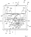
- FIG. 200 illustrates schematically an electronic unit 200, for instance electronic unit 120.
- Electronic unit 200 may comprise:
- Wake switch embodiments are described e.g. for a clip-on electronic encoding unit/module 120, 200.
- the present disclosure relates to features of an electronic unit/module 120, 200 that can be embodied as a re-usable clip-on module with a suitably configured pen injector for the purpose of recording doses that are delivered from the pen or other drug delivery device 100.
- This functionality may be of value to a wide variety of device users as a memory aid or to support detailed logging of dose history data.
- electronic unit/module 120, 200 could be configured to be connectable to a mobile device, e.g. a smart phone, or similar, to enable the dose history data to be downloaded from unit/module 120, 200 on a periodic basis.
- the wake switch Sw may be driven by rotation of the dose delivery mechanism within the injection device 100.
- this rotation may be observed in a number sleeve 400, which may be configured to rotate relative to a dose button during dispense, but e.g. not during dose-setting (dialing).
- the dose button may comprise button inner 300.
- Coupling feature 341 may comprise a proximal portion 341a and/or a middle portion 341b and/or a distal portion 341c. Distal portion 341c may be essentially identical with coupling portion 340.
- Coupling feature 341 may comprise a back face 342 (vertical), e.g. backwards facing or backwards directed with regard to the direction R of rotation of a ring member 402, see figure 4 .
- Coupling feature 341 may comprise a front face 343 relative to the direction R of rotation of a ring member 402.
- Front face 343 of coupling feature 340 may comprise:
- Coupling portion 340 may comprise:
- a distal face 360 may form the distal end of front coupling portion 352.
- a distal face 362 may form the distal end of back coupling portion 354.
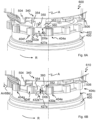
- Figure 4 illustrates ramped features 412d on teeth 404a to 404l of a number sleeve 400, more specific of a ring member 402 on a proximal end of number sleeve 400.
- Number Sleeve 400 e.g. of the pen device as described in WO 2014/033197 A1 or of another drug delivery device 100, may be configured to have ramped features, e.g. 412d, on each of the teeth, e.g. 404d, e.g. teeth of a clutch. There may be for instance 12 teeth 404a to 404e, see figure 4 .
- clutch 90 has teeth that are outwards directed. Teeth at the inner of proximal end of dial sleeve 62 are inwards directed. Contrary, in this application, teeth 404a to 404l on number/dial sleeve 400 are directed radially outwards. Thus the "clutch" of this embodiment, i.e. ring member 402 is different from the clutches.
- the clutch mechanism works in the same way as in the device described in the WO documents 2014/033195 A1 , WO 2014/033197 A1 - the clutch system still rotationally couples the button and number sleeve (via radial teeth) when the button is moved into a certain relative axial position, and rotationally decouples them in other relative axial positions.
- other clutch coupling mechanism may be used as well.
- no clutch mechanism may be involved.
- the clutch mechanism is based on the same design concept as in the WO document, but is a slightly different embodiment.
- number sleeve 400 and/or dial sleeve 400 may rotate, and the ramp features, e.g. 412d, of number sleeve 400 and/or dial sleeve 400 may engage with one of the two prongs (front coupling portion 352 and back coupling portion 354) on the coupling portion 340 of button inner 300, e.g. of a light pipe chassis or a chassis for other sensor units.
- This in turn may cause the flexible coupling portion 340 to bear rotationally against a ramped feature 702 on a button hold (button inner 300) within the chassis or on the chassis itself and to deflect upwards relative to the rest of the dose button and electronic module/unit 120, 200, thereby driving e.g.
- the user may release the dose button, e.g. button inner 300, which may spring axially outwards from the pen, e.g. in proximal direction. This may allow the coupling portion 340 on the flexible arm(s) 334l, 334r of the button inner 300 and/or chassis to once again deflect radially inwards and downwards, and switch Sw or another sensor may open or fulfill another switching operation.
- dose button e.g. button inner 300
- the coupling portion 340 on the flexible arm(s) 334l, 334r of the button inner 300 and/or chassis may once again deflect radially inwards and downwards, and switch Sw or another sensor may open or fulfill another switching operation.
- Number sleeve 400 may comprise circular central opening 401 and a coupling ring member 402 on its proximal end portion.
- Coupling ring member 402 may comprise teeth 404a to 400l, e.g. 12 teeth, arranged around the circular opening 401 and supported by a central ring of ring member 402.
- Teeth 404a to 400l may comprise:
- tooth 404d There may be the following faces on an inner portion of tooth, e.g. of tooth 404d:
- inner pockets e.g. 427d, 427e, 427f between two adjacent inner portions, see 406k.
- Outer pockets 429d, 429e, 429f may be arranged between two outer portions, see 408k.
- Vertical back face 416d of inner portion of a respective tooth, e.g. 404d, and back face 424d of outer portion may be arranged within the same plane, e.g. both back faces, e.g. 416d and 424d, may be coplanar to each other. However, other arrangements may also be used.
- At least one intermediate portion(s) 430e may be arranged at the bottom of inner pockets between two adjacent inner portions, e.g. 406k, e.g. a right intermediate portion 430e1 and a left intermediate portion 430e2.
- Proximal face(s), e.g. 432, of the at least one intermediate portion(s), e.g. 430e may face proximally P.
- the inner sub-portions, e.g. 440f, of outer portions, e.g. 408f, may have the function of a holding structure preventing re-engagement of coupling portion 340 with inner teeth 406a to 406l under specific conditions that are described in more detail below.
- Outer sub-portions, e.g. 442f, of the outer portions, e.g. 408f, may have a different function compared to the function of inner sub-portions, e.g. 440f.
- outer sub-portions, e.g. 442f may have the function of clutch teeth of a clutch for forwarding a rotational movement between different parts or for disabling forwarding of a rotational movement between these different parts of the clutch.
- Proximal (top) faces of inner sub-portions, e.g. 440f, and outer sub-portions, e.g. 442f, may be arranged within the same plane, i.e. be coplanar to each other, see for instance face 426d. However, other arrangements of these two proximal faces may also be used.
- leading edge there may be a leading edge, e.g. 444g, on each of the front faces, e.g. 420g, of an outer portion, e.g. 408k.
- the leading edge, e.g. 444g may be convex.
- the concave edge e.g.
- Inner part of the front surface or face, e.g. of front face 420g may be curved.
- An axis of curvature may be arranged parallel to longitudinal axis A.
- An outer part of the front surface, e.g. 420g, may be flat.
- Figure 4 illustrates a direction of rotation R relative to which the terms "front" and "back" are used.
- a back face, e.g. 460e, of inner sub-portion, e.g. 440e, and a back face, e.g. 462e, of an outer sub-portion, e.g. 442e, on the same tooth, e.g. 404e, may be arranged within the same plane.
- a back face, e.g. 462e, of an outer sub-portion, e.g. 442e, on the same tooth, e.g. 404e may be arranged within the same plane.
- other arrangements of these faces are possible as well.
- a front face, e.g. 480e, of outer sub portion 408e is also illustrated in figure 9B that is described in more detail below.
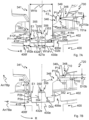
- Figures 5A and 5B illustrate coupling feature 340 as the button inner 300 travels axially, e.g. distally, straddling a single tooth 404f, e.g. the seventh tooth of ring member 402.
- coupling feature 340 may need to have at least two protrusions 352, 354 so that it can drop down into engagement with teeth 404a to 404l of the number/dial sleeve 400 in both conditions, i.e. either straddling a single tooth, e.g. 404f, see figures 5A and 5B , or between teeth, see figures 6A and 6B .
- Figure 5A illustrates a configuration 500 comprising a first axial position and a first angular position of button inner 300 (button inner) and of coupling portion 340 relative to ring member 402 and number sleeve 400.
- Distance D0a may be equal to the axial length of inner portion(s), e.g. 406f.
- the circumferential or angular width W1a of recess 350 may be slightly larger than the circumferential or angular width W2a of each inner portion, e.g. 406f.
- recess 350 and therefore also coupling portion 340 may engage with inner teeth, e.g. 406f, see figure 5A .
- Front ramped faces, e.g. 412f may fulfill a distal stop function for recess 350, e.g. for coupling portion 340.
- proximal faces, e.g. 432e, 432f, of intermediate portion(s), e.g. 430e, 430f may also be used as a distal stop face for the distal movement of button inner 300, e.g. of coupling portion 340.
- Figure 5B illustrates a second configuration 510 comprising a second axial position and the first angular position of button inner 300 (button inner) and of coupling portion 340 relative to ring member 402 and number sleeve 400.
- An axial distance D0b between distal face 360 of front coupling portion 352 and proximal face 432 of intermediate portion(s) 430e is less than axial distance D0a because button inner 300 has been moved distally by a user, see arrow Arr5Bd.
- Distance D0b may be greater than zero millimeter or may be zero millimeter.
- Coupling portion 340 is arranged above an inner pocket 427e between teeth 404e and 404f. There may be a first axial distance D0a between a distal face 360 of front coupling portion 352 and a proximal face 432 of intermediate portion(s) 430e. Distance D0a may be equal to the axial length of inner portion(s), e.g. 406f.
- a further configuration 610 comprises the second axial and the third angular position of button inner 300 (button inner) and of coupling portion 340 relative to number sleeve 400.
- An arrow Arr6Bd illustrates the distal movement of button inner 300 relative to number sleeve 400.
- Figure 7A illustrates a first configuration 700 of ring member 402, coupling feature 340 and ramped feature 702.
- Configuration 700 illustrates the axial and angular positions of these parts 402, 340 and 702 relative to each other.
- Figure 7A illustrates a cross section through coupling feature 340 (comb) showing engagement of coupling feature 340 with ring member 402 of number sleeve 400, e.g. within inner pocket 427e that is located between inner portions 406e and 406f that form teeth 406e and 406f.
- coupling feature 341 is contacting both a number sleeve tooth 406f on one side (left) and an optional ramped feature 702 on the button inner 300 (chassis) on the other (right) side, e.g. on front face 343 of coupling feature 341, more specifically on curved portion 345 of front face 343.
- Figure 7A illustrates the following geometrical dimensions:
- recess 350 can engage with inner tooth 406f.
- a circumferential or angular force F1 may be generated by rotation of ring member 402 by inner tooth 406 onto the back edge E1 of coupling member 340. As is explained in the following in more detail, angular force F1 is converted to a proximal movement of coupling feature 341, see e.g. arrow Arr7Bp in figure 7B .
- an arrow 701a indicates the contact portion between curved portion 345 of coupling feature 341 and ramped feature 702.
- An arrow 701b illustrates the contact portion between coupling portion 340 and inner tooth 406f.
- Guiding feature or ramped feature 702 on button inner 300 may comprising at least one ramp, e.g. a linear ramp or a curved ramp as described in more detail below.
- Ramped feature 702 may be arranged fixed relative to button inner 300 (chassis), e.g. ramped feature 702 may not rotate but is rotationally fixed on button inner 300 that does also not rotate but may move axially.
- An edge E2 may be formed by the border between distal portion 712 and middle portion 714. Edge E2 may be a convex edge. An edge E3 may be formed by the border between middle portion 714 and proximal portion 716. Edge E3 may be a concave edge.
- curved face 345 and curved face 710 may be engage complementary, e.g.:
- a point P2a is located on vertical front face 410f of inner portion/tooth 406f. Point P2a may be in direct mechanical contact with edge E1 on coupling portion 354. Thus, the force F1 impacted on point P2a may be forwarded via coupling feature 341 to point P1a and then to ramped feature 702. Ramped feature 702 may generate a proximal directed force F2 due to its complementary contact with curved portion 345. Resiliency of coupling feature 341 and/or resilient holding of coupling feature 341 on arms (ring portion) 334l and 334r may promote the conversion of force F1 to force F2.
- a distance D0b between distal face 360 of front coupling portion 352 and proximal face 432e of intermediate portion 430e may have the value mentioned above, e.g. of more than zero millimeter as illustrated in figure 7A or of zero millimeter.
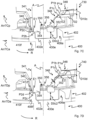
- Figure 7B illustrates a second configuration 720 of ring member 402, coupling feature 340 and ramped feature 702.
- Figure 7B illustrates a cross section through coupling feature 340 (comb) showing the coupling feature 340 to ride up the button inner 330, e.g. to ride up on ramped feature 702 of button inner 330.
- number sleeve 400 may deflect coupling portion 340 to the right, driving coupling portion 340 up the angled/curved face 710 on the ramped feature 702 of button inner 300 (chassis) to open up the gap D10b shown in figure 7B .
- the angle of this face 710 may start steep and may gradually get less steep as coupling portion 340 drives up this face. This may be because the force required to deflect coupling feature 340 elastically may increase as coupling portion 340 moves up axially. This may be in part due to the actuation force needed for actuating switch Sw.
- An arrow Arr7Bp illustrates the proximal displacement of coupling feature 341 comprising coupling portion 340.
- An arrow Arr7Ba illustrates the angular movement of ring member 402.
- a minimum distance D11c between edge E2 on ramp feature 702 and distal curved portion 346 of coupling portion 340 may still be zero millimeter due to direct mechanical contact of curved portion 345 and ramped feature 702.
- An arrow Arr7Cp illustrates the proximal displacement of coupling feature 341 comprising coupling portion 340.
- An arrow Arr7Ca illustrates the angular movement of ring member 402.
- Figure 7D illustrates a fourth configuration 740 of ring member 402, coupling feature 340 and ramped feature 702.
- Figure 7D illustrates a cross section through coupling feature 340, showing coupling feature 340 returning to the "left" and riding up the angled face 412f of tooth 404f, more specific of inner portion 406f of tooth 404f.
- Figure 7E illustrates a fifth relative configuration 750 of ring member 402, coupling feature 340 and ramped feature 702.
- Figure 7E illustrates a cross section through coupling feature 340, showing coupling feature 340 running along the top edge, see point P2e, or top surface of inner portion 406f of tooth 404f of number sleeve 400.
- the available 'width' of the teeth, e.g. of the inner teeth, e.g. 406f, of number/dial sleeve 400 may be limited, e.g. by the small lateral or radial dimensions of ring member 402. This means that to achieve the total required axial travel of coupling portion 340 to activate switch Sw, e.g. a micro-switch, or another sensor, based on the angled face on inner teeth alone, the necessary angled face on inner teeth would be too steep and would require too much torque to drive coupling portion 340 up this slope.
- switch Sw e.g. a micro-switch, or another sensor
- axially displacing coupling portion 340 may require additional applied user force to the button inner 300 (chassis), but this may only occur at the start of dispense, before the fluid pressure inside the cartridge may have risen and therefore when the user force to expel fluid is very low.
- Such an increase to dispense force at the start of dose is still likely to be below a typical force plateau during dose delivery (e.g. at 150 international units I.U. per second) and is therefore not expected to manifest in a noticeable increase in dispense force for the user.
- a distance D10e between middle portion 714 of curved face 710 on ramped feature 702 and distally facing segment 349 of curved portion 348 may now be greater than distance D10d.
- a distance D0e between distal face 360 and proximal face 432e of intermediate portion 430e may now be greater than distance D0d.
- Edge E2 may not make direct mechanical contact with curved portion 345 of front face 343.
- Edge E1 or distal face 362 of back coupling portion 354 may have reached and/or may make direct mechanical contact with a point P2e that is more proximal than point P2c on front ramped face 412f.
- a minimum distance D11e between edge E2 on ramp feature 702 and distal curved portion 346 of coupling portion 340 may be greater than distance D11d.
- coupling portion 340 has left inner pocket 427e.
- button inner 300 is still pressed, there is a radial deflection of coupling portion 340 that results in radial displacement of coupling portion 340 from inner portion 406f to adjacent inner sub-portion 440f of outer portion 408f of the same tooth 404f. This radial displacement is described in more detail in the following, e.g. with relation to figure 8 .
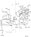
- Figure 8 illustrates the coupling feature 340 in a deflected state, e.g. deflected upwards and deflected radially outwards.
- the coupling portion 340 (comb) continues to run on the flat top face or faces 426d, 426e, 426f, 426g, etc. of the teeth 404d, 404e, 404f and 404g of the number/dial sleeve 400 and do not drop back down into outer pockets 429d, 429e and 429f between teeth 404e, 404f and 404g of the number/dial sleeve 400.
- Teeth 404e, 404f and 404g may be part of a clutch of the drug delivery device 100.
- the coupling portion 340 (comb) deflects axially upwards it may deflect also radially outwards, especially at the distal tip, e.g. as shown in figure 8 , arrow 810.
- a finite element analysis may have predicted that for 0.6 mm (millimeter) axial deflection, the tip may deflect 0.42 mm radially outwards. This radial outwards displacement may happen as the coupling portion 340 (comb) climbs out of the inner pocket 327e at the end of angled face 412d, 412e, 412f, etc. of one of the inner teeth (inner portion) 406d, 406e, 406f, etc.
- Configuration 800 illustrates coupling portion 340 on top of teeth 404f and 404g.
- There may be an angle A1 between the left portion 334l of ring 330, especially between the lower side thereof, in the axially (proximally) most deflected position, and a reference plane that is parallel to a plane in which coupling ring 402 is arranged.
- the reference plane may correspond to the plane in which the lower side of the left portion 334l of ring 330 is arranged in its released position, e.g. in the position where no axial deflection of left portion 334l occurs.
- Angle A1 may be in the range of 1 to 5 degrees or in the range of 2 to 4 degrees or within another appropriate range.
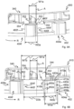
- Angular width W3a may be measured from leading edge 444f or inner sub-portion 440f of a respective tooth 404f to the back face of the same respective tooth 404f, e.g. the back face 460f of the inner sub-portion 440f of a respective tooth 404f, see figure 9 , corresponding back face 460e of tooth 404e.
- Angular width W1a of recessed portion 350 may be measured from back face of front coupling portion 352 to front face 355 of back coupling portion 354.
- the distal portion 340c of coupling portion 340 is supported by the inner sub-portion, e.g. 440f, etc. if above one of the teeth, e.g. 404f, etc.
- recess 350 may not engage with inner portions 406f in the radial outwards position of coupling portion 340.
- button inner 300 may move axially away from the top face of number/dial sleeve 400 and as it does so, the flexible switcher arms, e.g. left portion 334l of ring 330 and right portion 334r of ring 330 may relax back to their original state with the tip of coupling portion 340 (comb) on the smaller radius whereupon it can drop back down into inner pocket(s) 427l, etc. between inner portions, e.g. 406k and 406l, or into engagement with one of these inner portions, e.g. 406k and 406l, e.g. depending on the rotational end position of coupling ring 402 after dose delivery.
- the flexible switcher arms e.g. left portion 334l of ring 330 and right portion 334r of ring 330 may relax back to their original state with the tip of coupling portion 340 (comb) on the smaller radius whereupon it can drop back down into inner pocket(s) 427l, etc. between inner portions, e.g. 406
- the coupling portion 340 (comb) may be positioned radially over the ramped inner pockets 427k, 427l, etc. rather than over the flat surfaces/faces 426l, 426a. Therefore, coupling portion 340 will be not deflected axially and/or radially and switch Sw will not be activated during this depressing of button inner 300, see figure 10 .
- An arrow Arr10d indicates the proximal movement of button inner 300 and of coupling portion 340 in order to release coupling portion 340 from the flat faces 4261, 426a, etc.
- left portion 334l of ring 330 and/or right portion of ring 330 may be straight or may have a different form, e.g. cranked.
- the benefit to waking the electronic module 120, 200 on or shortly before the beginning of dose delivery may be that power consumption of the dose capture system can be limited by having the capture system active for the shortest possible time.
- IR-LED infrared - light emitting diode
- an actuating unit 301 for a drug delivery device 100 may comprise:
- a rotating member may comprise:
- a number sleeve 400 may be claimed comprising the actuating unit 301 and the rotating member.
- a drug delivery device 100 is disclosed, e.g. pen type device, comprising the actuating member 301 and/or the rotating member, e.g. ring member 330.
- a method for actuating a drug delivery device 100 may comprise:
- a system 98 comprising:
Landscapes
- Health & Medical Sciences (AREA)
- Vascular Medicine (AREA)
- Engineering & Computer Science (AREA)
- Anesthesiology (AREA)
- Biomedical Technology (AREA)
- Heart & Thoracic Surgery (AREA)
- Hematology (AREA)
- Life Sciences & Earth Sciences (AREA)
- Animal Behavior & Ethology (AREA)
- General Health & Medical Sciences (AREA)
- Public Health (AREA)
- Veterinary Medicine (AREA)
- Infusion, Injection, And Reservoir Apparatuses (AREA)
Priority Applications (6)
| Application Number | Priority Date | Filing Date | Title |
|---|---|---|---|
| EP21315262.2A EP4249016A1 (de) | 2022-03-24 | 2022-03-24 | Betätigungseinheit für eine medikamentenabgabevorrichtung und verwandte gegenstände |
| JP2024556085A JP2025510720A (ja) | 2022-03-24 | 2022-11-30 | 薬物送達デバイス用の作動ユニット及び関連物品 |
| PCT/EP2022/083755 WO2023179902A1 (en) | 2022-03-24 | 2022-11-30 | Actuating unit for a drug delivery device and related items |
| CN202280093566.6A CN118871151A (zh) | 2022-03-24 | 2022-11-30 | 用于药物递送装置的致动单元及相关物品 |
| EP22823416.7A EP4499177A1 (de) | 2022-03-24 | 2022-11-30 | Betätigungseinheit für eine arzneimittelabgabevorrichtung und zugehörige artikel |
| US18/850,019 US20250205432A1 (en) | 2022-03-24 | 2022-11-30 | Actuating unit for a drug delivery device and related items |
Applications Claiming Priority (1)
| Application Number | Priority Date | Filing Date | Title |
|---|---|---|---|
| EP21315262.2A EP4249016A1 (de) | 2022-03-24 | 2022-03-24 | Betätigungseinheit für eine medikamentenabgabevorrichtung und verwandte gegenstände |
Publications (1)
| Publication Number | Publication Date |
|---|---|
| EP4249016A1 true EP4249016A1 (de) | 2023-09-27 |
Family
ID=81454670
Family Applications (2)
| Application Number | Title | Priority Date | Filing Date |
|---|---|---|---|
| EP21315262.2A Ceased EP4249016A1 (de) | 2022-03-24 | 2022-03-24 | Betätigungseinheit für eine medikamentenabgabevorrichtung und verwandte gegenstände |
| EP22823416.7A Pending EP4499177A1 (de) | 2022-03-24 | 2022-11-30 | Betätigungseinheit für eine arzneimittelabgabevorrichtung und zugehörige artikel |
Family Applications After (1)
| Application Number | Title | Priority Date | Filing Date |
|---|---|---|---|
| EP22823416.7A Pending EP4499177A1 (de) | 2022-03-24 | 2022-11-30 | Betätigungseinheit für eine arzneimittelabgabevorrichtung und zugehörige artikel |
Country Status (5)
| Country | Link |
|---|---|
| US (1) | US20250205432A1 (de) |
| EP (2) | EP4249016A1 (de) |
| JP (1) | JP2025510720A (de) |
| CN (1) | CN118871151A (de) |
| WO (1) | WO2023179902A1 (de) |
Citations (7)
| Publication number | Priority date | Publication date | Assignee | Title |
|---|---|---|---|---|
| US6004297A (en) | 1998-01-30 | 1999-12-21 | Novo Nordisk A/S | Injection syringe |
| WO2005018721A1 (en) | 2003-08-12 | 2005-03-03 | Eli Lilly And Company | Medication dispensing apparatus with triple screw threads for mechanical advantage |
| WO2014033195A1 (en) | 2012-08-31 | 2014-03-06 | Sanofi-Aventis Deutschland Gmbh | Drug delivery device |
| WO2014033197A1 (en) | 2012-08-31 | 2014-03-06 | Sanofi-Aventis Deutschland Gmbh | Drug delivery device |
| US9108002B2 (en) | 2005-01-21 | 2015-08-18 | Novo Nordisk A/S | Automatic injection device with a top release mechanism |
| US20210170111A1 (en) * | 2017-12-21 | 2021-06-10 | Sanofi | Drive Mechanism with Noise Reduction |
| WO2021191329A1 (en) * | 2020-03-27 | 2021-09-30 | Sanofi | Electronic system for a drug delivery device |
-
2022
- 2022-03-24 EP EP21315262.2A patent/EP4249016A1/de not_active Ceased
- 2022-11-30 WO PCT/EP2022/083755 patent/WO2023179902A1/en not_active Ceased
- 2022-11-30 US US18/850,019 patent/US20250205432A1/en active Pending
- 2022-11-30 JP JP2024556085A patent/JP2025510720A/ja active Pending
- 2022-11-30 CN CN202280093566.6A patent/CN118871151A/zh active Pending
- 2022-11-30 EP EP22823416.7A patent/EP4499177A1/de active Pending
Patent Citations (7)
| Publication number | Priority date | Publication date | Assignee | Title |
|---|---|---|---|---|
| US6004297A (en) | 1998-01-30 | 1999-12-21 | Novo Nordisk A/S | Injection syringe |
| WO2005018721A1 (en) | 2003-08-12 | 2005-03-03 | Eli Lilly And Company | Medication dispensing apparatus with triple screw threads for mechanical advantage |
| US9108002B2 (en) | 2005-01-21 | 2015-08-18 | Novo Nordisk A/S | Automatic injection device with a top release mechanism |
| WO2014033195A1 (en) | 2012-08-31 | 2014-03-06 | Sanofi-Aventis Deutschland Gmbh | Drug delivery device |
| WO2014033197A1 (en) | 2012-08-31 | 2014-03-06 | Sanofi-Aventis Deutschland Gmbh | Drug delivery device |
| US20210170111A1 (en) * | 2017-12-21 | 2021-06-10 | Sanofi | Drive Mechanism with Noise Reduction |
| WO2021191329A1 (en) * | 2020-03-27 | 2021-09-30 | Sanofi | Electronic system for a drug delivery device |
Also Published As
| Publication number | Publication date |
|---|---|
| US20250205432A1 (en) | 2025-06-26 |
| JP2025510720A (ja) | 2025-04-15 |
| WO2023179902A1 (en) | 2023-09-28 |
| CN118871151A (zh) | 2024-10-29 |
| EP4499177A1 (de) | 2025-02-05 |
Similar Documents
| Publication | Publication Date | Title |
|---|---|---|
| US20230158246A1 (en) | Electronic Module and Drug Delivery Device | |
| US20230001096A1 (en) | Medicament Injection Device | |
| JP7763774B2 (ja) | 薬物送達デバイス用の電子システム | |
| US20230330345A1 (en) | Drug delivery device with electronic system | |
| US12544513B2 (en) | Electronic system for a drug delivery device | |
| US20250205432A1 (en) | Actuating unit for a drug delivery device and related items | |
| US20240269390A1 (en) | Drug delivery device and method for operating a drug delivery device | |
| US20240091453A1 (en) | Electronic System for a Drug Delivery Device and Drug Delivery Device | |
| US20230398294A1 (en) | Electronic system for a drug delivery device and drug delivery device | |
| US20230112820A1 (en) | Electronic System for a Drug Delivery Device | |
| US20230347065A1 (en) | Electronic system for a drug delivery device, drug delivery device, and associated method | |
| EP4126122B1 (de) | Schalteranordnung für ein elektronisches system eines arzneimittelabgabegeräts | |
| US20240293625A1 (en) | Data Logging Device for Monitoring Use of an Injection Device |
Legal Events
| Date | Code | Title | Description |
|---|---|---|---|
| PUAI | Public reference made under article 153(3) epc to a published international application that has entered the european phase |
Free format text: ORIGINAL CODE: 0009012 |
|
| STAA | Information on the status of an ep patent application or granted ep patent |
Free format text: STATUS: THE APPLICATION HAS BEEN PUBLISHED |
|
| AK | Designated contracting states |
Kind code of ref document: A1 Designated state(s): AL AT BE BG CH CY CZ DE DK EE ES FI FR GB GR HR HU IE IS IT LI LT LU LV MC MK MT NL NO PL PT RO RS SE SI SK SM TR |
|
| STAA | Information on the status of an ep patent application or granted ep patent |
Free format text: STATUS: THE APPLICATION HAS BEEN REFUSED |
|
| 18R | Application refused |
Effective date: 20231015 |