EP4249228A1 - Vorrichtung und verfahren zum verdichten eines pulvers - Google Patents
Vorrichtung und verfahren zum verdichten eines pulvers Download PDFInfo
- Publication number
- EP4249228A1 EP4249228A1 EP23164127.5A EP23164127A EP4249228A1 EP 4249228 A1 EP4249228 A1 EP 4249228A1 EP 23164127 A EP23164127 A EP 23164127A EP 4249228 A1 EP4249228 A1 EP 4249228A1
- Authority
- EP
- European Patent Office
- Prior art keywords
- compaction
- piston
- powder
- shutter
- compacting
- Prior art date
- Legal status (The legal status is an assumption and is not a legal conclusion. Google has not performed a legal analysis and makes no representation as to the accuracy of the status listed.)
- Pending
Links
Images


Classifications
-
- B—PERFORMING OPERATIONS; TRANSPORTING
- B30—PRESSES
- B30B—PRESSES IN GENERAL
- B30B11/00—Presses specially adapted for forming shaped articles from material in particulate or plastic state, e.g. briquetting presses, tabletting presses
- B30B11/02—Presses specially adapted for forming shaped articles from material in particulate or plastic state, e.g. briquetting presses, tabletting presses using a ram exerting pressure on the material in a moulding space
- B30B11/04—Presses specially adapted for forming shaped articles from material in particulate or plastic state, e.g. briquetting presses, tabletting presses using a ram exerting pressure on the material in a moulding space co-operating with a fixed mould
-
- B—PERFORMING OPERATIONS; TRANSPORTING
- B30—PRESSES
- B30B—PRESSES IN GENERAL
- B30B11/00—Presses specially adapted for forming shaped articles from material in particulate or plastic state, e.g. briquetting presses, tabletting presses
- B30B11/005—Control arrangements
-
- B—PERFORMING OPERATIONS; TRANSPORTING
- B30—PRESSES
- B30B—PRESSES IN GENERAL
- B30B11/00—Presses specially adapted for forming shaped articles from material in particulate or plastic state, e.g. briquetting presses, tabletting presses
- B30B11/02—Presses specially adapted for forming shaped articles from material in particulate or plastic state, e.g. briquetting presses, tabletting presses using a ram exerting pressure on the material in a moulding space
-
- B—PERFORMING OPERATIONS; TRANSPORTING
- B30—PRESSES
- B30B—PRESSES IN GENERAL
- B30B15/00—Details of, or accessories for, presses; Auxiliary measures in connection with pressing
- B30B15/0005—Details of, or accessories for, presses; Auxiliary measures in connection with pressing for briquetting presses
- B30B15/0017—Deairing means
Definitions
- the present invention generally relates to the field of solid blocks or tablets consisting of a compacted powder and intended for aqueous solution before use. It relates more particularly to a device and a method for compacting a powder.
- the invention finds a particularly advantageous application in the mass production of solid cosmetics, detergents or food supplements. It also relates to a powder composition suitable for the manufacture of a compacted powder using the device and the method. In a preferred but non-limiting application, the invention relates to solid cosmetics.
- Solid cosmetics to be rehydrated make it possible to meet both economic and environmental constraints. Indeed, their solid and dry form avoids the transport and packaging of a large quantity of water, water can represent up to 90% of the weight of a shower gel, a liquid shampoo or a toothpaste.
- solid cosmetics intended to allow reconstitution before use of cosmetics in liquid form the user is encouraged to reuse the containers they already have to rehydrate the new solid cosmetics they obtain. . Once rehydrated, they can reconstitute liquid soaps, shower gels and liquid shampoos.
- the solid cosmetics thus used generally consist of a compacted powder, for example in the form of tablets or sticks which facilitate transport and application.
- powder compaction devices comprising an enclosure in which is placed a metal capsule in which the blush powder is agglomerated or compacted by means of a piston sliding in the enclosure.
- the assembly consisting of the capsule and the makeup tablet is ejected from the device, the capsule ensuring the consistency of the whole and the protection of the tablet against impacts.
- Such a device is not suitable for producing solid cosmetics as envisaged by the invention which do not include a metal capsule receiving the powder.
- devices for compacting bath salts comprising a compaction enclosure and a piston.
- the bottom of the enclosure and the piston have, for example, complementary hemispherical shapes to obtain spherical bath salts.
- a capsule once the powder is compacted, it is difficult to remove the solid cosmetic obtained from the enclosure without risk of damaging it.
- the compacted powder is not enclosed in the bottom of an enclosure since the compaction surface, namely the shutter, can be moved towards the release position, which makes it possible to extract solid cosmetics.
- the piston when the shutter is in the release position, the piston can even continue its travel towards the filling opening to bring out or eject the solid cosmetic out of the compaction chamber.
- the piston remains positioned in the compaction chamber between two compaction cycles, that is to say between the manufacture of two solid cosmetics. It is therefore not necessary to remove the piston from the compaction chamber to insert the powder, as is the case in the devices of the prior art.
- the device according to the invention makes it possible to precisely dose the quantity of powder to be compacted by choosing the starting position of the piston in the compaction chamber.
- the main direction is substantially vertical, the filling opening being located above the piston.
- the shutter is movable in translation in a direction substantially orthogonal to the main direction. This movement simplifies the implementation of the shutter while maintaining effective separation of the solid cosmetic and the shutter. In addition, such kinematics of movement of the shutter make it possible to optimize the recovery of compaction efforts by the shutter.
- the compression unit comprises: means for measuring a force exerted by the actuator on the piston; a control unit programmed to determine, based on the force, a speed of movement of the piston.
- the compression unit comprises: means for measuring a stroke of the piston; a control unit programmed to determine, based on the stroke, at least one of a speed of movement of the piston and a force exerted by the actuator on the piston.
- Adapting the speed of movement of the piston makes it possible to quickly empty the air contained in the powder in order to increase the production rate while compacting the powder evenly.
- the compaction device comprises a support structure on which the shutter and the actuator are fixed, the compaction chamber and the piston being held removably relative to the support structure.
- the shape of the solid cosmetic or the formed block can therefore be modified simply by interchanging the compaction chamber with another compaction chamber of the desired shape.
- the compaction chamber is a cylinder of revolution having a diameter of between 10 and 30 mm.
- Such a shape allows radial stresses (perpendicular to the direction of compaction) to be well distributed over the entire surface of the cylinder.
- Such a compaction chamber is therefore very resistant.
- the compaction device is then particularly suited to the manufacture of solid cosmetics in series and at a high rate.
- the compaction device includes only one shutter for all of the compaction chambers.
- the compaction device by compacting the powder very strongly, makes it possible to obtain very resistant solid cosmetics but also to use a wide variety of powders such as powders comprising a large number of ingredients, for example greater than five or six.
- the powder is compacted so as to reduce the duration of the compaction cycle while ensuring homogeneous compaction.
- the decomposition of the compaction into an initial phase and a subsequent phase makes it possible in particular to quickly empty a large quantity of the air contained in the powder then to obtain homogeneous compaction of the powder by slowing down the speed of the piston.
- the compaction process according to the invention makes it possible to produce solid cosmetics in the form of compacted powder at a high rate and at low cost. In fact, it makes it possible to reduce or simplify manual operations by automating a large number of manufacturing steps.
- the first set speed is imposed on the piston and when the force exerted by the actuator on the piston or a stroke of the piston is greater than the threshold value, the second set speed is imposed on the piston.
- the method comprises, after compaction, moving the piston opposite the filling opening. This helps release the pressure between the solid cosmetic and the filler against which it was compacted. The separation of the solid cosmetic from the obturator is then facilitated.
- the method comprises, after compaction, moving the shutter from the closed position to the release position in order to be able to remove the solid cosmetic from its compaction chamber.
- the method comprises, after moving the shutter from the closed position to the release position, a movement of the piston in the direction of the filling opening.
- the method comprises, after moving the shutter from the closed position to the release position, the extraction of the compacted powder from the compaction chamber.
- the piston limits or facilitates a delicate manual operation of extracting the solid cosmetic.
- the shutter by moving laterally, can recover the solid cosmetics, for example by sweeping them towards a receptacle. Since the filling opening is located above the piston, the solid cosmetic does not fall when the piston pushes it out of the chamber.
- the invention also proposes a powder composition for the manufacture of solid cosmetics to be reconstituted in an aqueous medium comprising a compaction promoter which comprises a compacting agent in solid form or a compacting agent in liquid form, the compaction promoter being between 5% and 30% by weight, relative to the total weight of the composition.
- the use of a compaction promoter improves the cohesion of the compacted powder and therefore the solidity of the solid cosmetics formed.
- they make the powder composition more difficult to handle before compacting (risk of lumps and heating).
- the proportion of compaction promoter is both sufficiently low so that the powder composition is fine and fluid before its compaction, which makes it possible to easily fill the compaction chamber, and at the same time sufficiently high so that solid cosmetic blocks, i.e. compacted powder, are impact resistant.
- the compacting agent in solid form is between 2% and 30% by weight, relative to the total weight of the composition and is for example selected from a group comprising: zinc citrate, maltrodextrin, trisodium citrate dihydra.
- the compacting agent in liquid form is between 2% and 10% by weight, relative to the total weight of the composition and is preferably selected from a group comprising: maltitol, a flavor, a scent.
- the compacting agent in liquid form is not in the aqueous phase. This makes it possible in particular to improve the conservation of solid cosmetics.
- the compacting agent in liquid form comprises less than 1% by weight of water.
- At least 95% of the particles constituting the composition have a particle size less than 1 mm, which improves the resistance of the solid cosmetic.
- the interfaces between two particles within the solid cosmetic are sufficiently small so that the detachment of one of these interfaces does not lead to the breakage of the entire solid cosmetic.
- 95% of the particles constituting the composition have a particle size of between 0.5 mm and 1 mm.
- the composition comprises an effervescent agent of between 12% and 60% by weight, relative to the total weight of the composition, preferably selected from a group comprising: bicarbonate sodium, anhydrous citric acid.
- effervescent agent of between 12% and 60% by weight, relative to the total weight of the composition, preferably selected from a group comprising: bicarbonate sodium, anhydrous citric acid. This quantity of effervescent agent allows rapid dissolution of the solid cosmetic in an aqueous medium for its use.
- the composition comprises a moisturizing agent of between 5% and 60% by weight, relative to the total weight of the composition, for example selected from a group comprising: erythritol, polysaccharide, anionic polysaccharide, an extract plant oil, a dry extract of aloe vera.
- the composition comprises a gelling agent of between 10% and 20% by weight, relative to the total weight of the composition, preferably selected from a group comprising: sodium alginate, xanthan gum, sodium polyacrylate .
- the composition comprises a pH regulator of between 3% and 40% by weight, relative to the total weight of the composition, preferably selected from a group comprising: sodium gluconate, anhydrous citric acid, monosodium citrate. This quantity of pH regulator gives the solution comprising the dissolved solid cosmetic an appropriate pH.
- the composition comprises a preservative of between 5% and 20% by weight, relative to the total weight of the composition, preferably selected from a group comprising: sodium benzoate, potassium sorbate, isopropyl methylphenol, sodium gluconate.
- a preservative of between 5% and 20% by weight, relative to the total weight of the composition, preferably selected from a group comprising: sodium benzoate, potassium sorbate, isopropyl methylphenol, sodium gluconate.
- the invention finally proposes a solid cosmetic to be dissolved in an aqueous medium obtained by compacting a composition as described above by implementing the process described above.
- the powder here is a composition made powdery by grinding or pulverization.
- the powder has, for example, a particle size of less than 1 mm.
- Powder 2 is a powder composition which includes particles and which is here intended for the manufacture of solid cosmetics.
- the powder composition is in a dispersed state before its compaction by the compacting device 1; it is then referred to below as “powder”. After its compaction by the compacting device 1, the powder composition is referred to as “solid cosmetic”.
- this term is not restrictive and must be considered equivalent to compacted block in the context of the manufacture of detergents or food supplements.
- each compaction chamber 11, when filled with said part of the powder 2, makes it possible to manufacture a solid cosmetic.
- this part of the powder 2 filling the compaction chamber 11 is more simply referred to as “the powder” filling the compaction chamber 11.
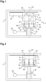
- the compaction device 1 also comprises a support structure 3 securely holding the compaction chambers 11, the shutter 20 and the compression unit 30 so as to compensate for the efforts of the compression unit 30 to ensure the compaction of the powder 2 against shutter 20.
- the compaction device 1 here comprises two actuators 31.
- Each compaction chamber 11 has a general cylindrical shape in that it comprises an internal surface which is cylindrical and whose generators extend parallel to a main direction D1 which is here the vertical direction (corresponding to the up-down direction on THE figures 1 and 2 ).
- the compaction chambers 11 will hereinafter be designated indifferently by the terms “compaction cylinders” 11 or “compaction chambers” 11.
- the compaction cylinders 11 appear as a dotted line on the figures 1 and 2 , each dotted line represents more particularly a generator of a compaction cylinder 11.
- the compaction device 1 preferably comprises at least two compaction chambers 11 and preferably more than ten compaction chambers 11.
- the compaction device 1 comprises sixty compaction chambers 11 distributed in a matrix of fifteen per four.
- the compaction device 1 is particularly suitable for the mass production of solid cosmetics.
- the compacting device 1 makes it possible, for example, to produce between 1 and 100 solid cosmetics per minute.
- each compaction cylinder 11 comprises two opposite openings located respectively at its two bases.
- Each compaction cylinder 11 thus comprises a filling opening 12, through which the powder 2 is put into the compaction cylinder 11, and a working opening 13 through which the associated piston 40 passes.
- the filling openings 12 are located above, and here vertically, the working openings 13.
- each compaction cylinder 11 has more specifically an internal surface extending along a cylinder of revolution whose diameter is between 10 mm and 30 mm.
- the solid cosmetics produced are then in the shape of a cylinder of revolution.
- the length of the compaction cylinders 11, that is to say their dimension along the main direction D1, is for example between 5 mm and 200 mm.
- the compaction cylinders may have a cross section of another shape such as a hexagonal or rectangular section.
- the compaction device 1 comprises a cylinder block 10 within which the compaction cylinders 11 are held or arranged.
- the cylinder block 10 is here a support part of generally parallelepiped shape.
- all the compaction cylinders 11 installed within the cylinder block 10 are identical.
- the cylinder block 10 has a filling face 14 that is substantially flat and extends substantially horizontally.
- Each filling opening 12 opens at the level of the filling face 14.
- the compaction cylinders 11 are more specifically mounted removably in the cylinder block 10.
- Each compaction cylinder 11 is thus formed by an interchangeable sheath, which makes it possible to adapt the shape that one wishes to give to the solid cosmetic. It is thus possible to mount compacting cylinders of rectangular or square section to form solid parallelepiped cosmetics. Means are also provided for fixing the cylinders to the cylinder block 10, for example threads and passages in the compacting cylinders 11 and in the cylinder block 10 so as to secure the latter by means of screws.
- the compaction cylinders 11, that is to say here the sleeves, are made of metallic material such as for example aluminum, stainless steel or polytetrafluoroethylene.
- the compaction cylinders could be formed by bores passing through a solid cylinder block.
- the pistons 40 are positioned opposite the filling openings 12.
- the pistons 40 are movable through the working openings 13.
- the compression unit 30 comprises a support plate 32 on which the pistons 40 are mounted.
- the pistons 40 are here mounted on a front face 33 of the support plate 32.
- the actuators 31 for their part exert their force at the level of a rear face 34 of the support plate 32 opposite the front face 33.
- the faces 33, 34 of the support plate 32 extend here substantially horizontally.
- Each piston 40 comprises more particularly a head 41, the shape of which is adapted to or complementary to that of the corresponding compaction cylinder 11, and a rod 42.
- Each head 41 thus has here a cylindrical shape with a diameter equal to the diameter of the compaction cylinder 11 associated, with a clearance to allow nesting in the latter.
- the rods 42 here have a width, corresponding to a dimension in a direction orthogonal to the main direction D1, less than the diameter of the heads 41.
- the pistons 40 are also interchangeable.
- the pistons 40 are for example removably fixed on the support plate 32.
- the heads 41 of the pistons 40 are interchangeable, the rods remaining fixed to the support plate 32.
- the heads 41 can by examples being screwed onto the rods 42.
- the heads 41 of the pistons 40 are made of polytetrafluoroethylene (PTFE), which limits friction in the compacting cylinders 11.
- the rods 41 are for example made of aluminum, steel or stainless steel.
- each piston 40 is adapted to be moved by the actuators 31 in the corresponding compaction cylinder 11, that is to say in its associated compaction cylinder 11.
- FIG 2 illustrates a state of the compacting device 1 in which the heads 41 of the pistons 40 are located approximately halfway between the working openings 13 and the filling openings 12.
- Each piston 40 is more specifically adapted to be moved according to a generator of its associated compaction cylinder 11.
- the pistons 40 are thus all adapted to be moved according to the main direction D1.
- the pistons 40 by being moved by the actuators 31, allow the compaction of the powder 2 filling the compaction cylinders 11 against the shutter 20, the latter then being in the closed position.
- the compression unit 30 also comprises a control unit 35 comprising at least one processor, at least one memory, at least one actuator control interface as well as a communication interface with sensors or measuring means.
- the control unit is programmed to control the actuators 31.
- the control unit 35 is in particular adapted to control the actuators 31 so as to impose a determined speed of movement on the pistons 40.
- the compression unit 30 can also include means for measuring a force exerted by the actuators 31 on the support plate 32, and therefore indirectly on each piston 40.
- This means for measuring a force is for example an electronic circuit making it possible to measure the intensity and/or voltage of the electric current supplied to the actuators 31 to make them operate.
- the control unit 35 is then programmed to determine, on the basis of this force exerted by the actuators 31 on the support plate 32, the speed of movement of the pistons 40.
- the compression unit 30 may also include means for measuring a stroke of the pistons 40.
- This means for measuring the stroke is for example an integrator integrating the speed of the pistons 40 over time on the basis of the electric current supplied. to the actuators 31.
- This means of measuring the stroke can also be a displacement sensor measuring the displacement of the actuators 31 or even of the support plate 32.
- the control unit 35 is then programmed to determine, on the basis of this stroke, the speed of movement of the pistons 40.
- the control unit 35 is for example programmed by means of instructions entered manually by an operator (for example via set speeds as described below).
- the control unit 35 is adapted to control the speed of the pistons 40 as a function of a compression ratio, itself determined on the basis of a difference between a starting position of the pistons 40, before compaction, and an instantaneous position of the pistons 40 during compaction.
- the shutter 20 comprises a substantially flat compaction face 21.
- the compaction face 21 is designed to extend into contact with the filling face 12 of the cylinder block 10 when the shutter 20 is in the closed position. In the closed position, the compaction face 21 extends more specifically against the filling face 14 so as to close the filling openings 12.
- closing is meant here that the shutter 20 closes, at the level of the filling openings. filling 12, the compaction cylinders 11 so as to prevent the powder 2 from coming out but still allows the air present in the compaction cylinders 11 to escape. In other words, “closing” here means making it airtight to the powder 2 but not to air.
- the shutter 20 has for example the shape of a plate whose thickness, here its dimension along the main direction D1, is sufficiently large to resist the compaction of the powder 2, that is to say here not to deform during compaction.
- the thickness of the shutter 20 is for example between 3 mm and 200 mm.
- the shutter 20 can be made of metallic material, for example stainless steel, polytetrafluoroethylene or a combination of these materials.
- the shutter 20 is movable between the release position, as shown on the figure 1 and on the Figure 3 , and the closed position as shown on the figure 2 .
- the shutter 20 leaves the filling openings 12 accessible, which makes it possible to fill the compacting cylinders 11 or, conversely, to remove the solid cosmetics.
- the shutter 20 is more specifically movable parallel to the filling face 14 of the cylinder block, and more specifically in contact with the latter.
- the shutter 20 is movable horizontally, that is to say in a plane substantially orthogonal to the direction main D1. This makes it possible in particular to ensure effective separation of solid cosmetics from the compacting face 21 of the shutter 20 against which they were compacted.
- the shutter 20 is here movable in translation, in a direction orthogonal to the main direction D1, which simplifies its implementation.
- the shutter 20 is here mounted on the support structure 3 by means of guide rails 22.
- two rails 22 are located laterally, that is to say along the two opposite sides of the compaction face 21 which extend in the direction of translation of the shutter 20. As illustrated in Figure 3 , this makes it possible to leave the cylinder block 10 easily accessible when the shutter 20 is in the release position.
- the compaction device 1 comprises for example a dedicated actuator (not shown) also controlled by the control unit 35.
- the compaction process is part of a broader process for manufacturing solid cosmetics or solid blocks of compacted powder.
- This process for manufacturing solid cosmetics includes two main phases: a first phase of preparing powder 2 and a second phase of compacting powder 2.
- the first phase may include grinding solid ingredients and/or mixing ingredients already in powder form.
- the composition of powder 2 is described in detail later. However, it can be noted at this stage that the compaction device 1 and the compaction method make it possible to effectively compact powders whose proportion of liquid is not negligible, for example because it is greater than 2% by weight, which are difficult to compact with the devices according to the prior art.
- the second phase of compaction of powder 2 corresponds to the implementation of the compaction process presented in Figure 4 .
- the compaction process begins with step E1 of filling the compaction cylinders 11 with the powder 2.
- the filling can be carried out automatically, for example using an injector mounted on a robotic arm and connected to a tank filled with powder 2, or manually by an operator.
- the pistons 40 are positioned at a starting position PD inside and at the bottom of the compaction cylinders 11, that is to say near the working openings 13.
- the starting position PD is here predetermined according to the quantity of powder 2 desired to form solid cosmetics. It is for example determined by considering the final mass that a solid cosmetic must have and the density of the powder 2.
- the mass of powder 2 deposited in each compacting cylinder 11 is for example between 2 g and 40 g.
- a volume of powder 2 greater than the volume of all of the compaction cylinders 11 is used to ensure that each compaction cylinder 11 is completely filled.
- the surplus powder 2 is then recovered for reuse.
- the excess powder 2 can be recovered by moving the shutter 20 from the release position to the closed position (see next step).
- step E2 of closing the filling openings 12.
- the dedicated actuator translates the shutter 20 from the release position to the closed position.
- the powder 2 is interposed between the corresponding piston 40 and the shutter 20.
- step E3 of compacting the powder 2 included in each compacting cylinder 11.
- the control unit 35 determines in particular the speed of movement of the pistons 40.
- the compaction that is to say the movement of the pistons 40 from the starting position PD to a final position PF, comprises two successive phases P1, P2 as represented on the figures 5 And 6 .
- THE compaction also includes the starting and stopping of the pistons 40 which take place respectively before and after the two phases P1, P2.
- the final position PF corresponds to the position of the pistons 40 at the end of the compaction of the powder 2, in the sense that, at the final position PF, the solid cosmetics are formed. It thus corresponds to a final compression rate of the powder 2.
- the Figure 6 illustrates here the stroke of the pistons 40 along the main direction D1.
- Compaction begins with an initial phase P1 which is characterized by the expulsion of the air present in the powder and in the compaction cylinders 11.
- initial phase P1 which is characterized by the expulsion of the air present in the powder and in the compaction cylinders 11.
- the pistons 40 advance quickly.
- the pistons 40 are then moved by the actuators 31 according to a first set speed called expulsion speed V1 which is determined by the control unit 35. It is selected to quickly expel the majority of the air contained in the powder 2
- the pistons 40 generally advance at the expulsion speed V1 during the initial phase.
- the expulsion speed can be constant, as shown in the Figure 5 , or vary, for example linearly, in a given interval.
- the control unit 35 is for example programmed to impose the expulsion speed V1 on the pistons 40 until the stroke of the pistons 40, measured using means for measuring a stroke of the pistons 40, reaches a first value threshold. Equivalently, the pistons 40 can be moved at the expulsion speed V1 until a compression ratio reaches a second threshold value, for example between 50% and 90%.
- the first and second threshold values depend for example on the density of the powder 2 or on a quantity of compaction promoter within the powder 2.
- the initial phase P1 continues until the inversion time T corresponding to the moment from which the stroke of the pistons 40 is greater than the first threshold value (or the compression ratio greater than the second threshold value).
- the inversion time T corresponds to the intermediate position PI of the pistons 40.
- the second threshold value (which relates to the compression ratio) is approximately 65%.
- the compression ratio is here calculated as the ratio of i) the difference between the instantaneous position and the starting position PD of the pistons 40, on ii) the difference between a flush position PA (when the pistons 40 are at the level of the filling openings 12) and the starting position PD of the pistons 40.
- a subsequent phase P2 of compression of the powder begins which is characterized in particular by the plastic deformation of the particles composing the powder 2 so as to ensure their agglomeration by sintering.
- the pistons 40 are then moved by the actuators 31 according to a second set speed called compression speed V2 which is determined by the control unit 35.
- the compression speed V2 is strictly lower than the expulsion speed V1.
- the compression speed V2 is less than the lower limit of this given interval.
- the rotation speed of the drive motor determining the expulsion speed V1 and the compression speed V2 is for example between 500 and 4000 rpm, i.e. speeds between 1 mm/s and 400 mm/s (millimeters/seconds).
- the expulsion speed V1 and the compression speed V2 are between 100 mm/s and 250 mm/s.
- the compression speed V2 is for example twice as low as the expulsion speed V1.
- This slower advance of the pistons 40 makes it possible to obtain homogeneous compaction of the powder 2.
- the applicant has in fact demonstrated that a compression speed V2 that is too high induces a compaction gradient in the solid cosmetic, the latter being increasingly more compact towards the end located against the shutter 20.
- This slower advance aims to approach a quasi-static process and to achieve high compression, for example greater than 80%.
- the inversion time T can also correspond to the moment from which a torque exerted by the electric motor becomes greater than a third threshold value.
- the powder 2 offers little resistance to the movement of the pistons. Once the subsequent phase P2 begins, the powder 2 puts up a great resistance, it is then preferable that the torque supplied is greater than that of the initial phase P1.
- the third threshold value can be expressed absolutely or as a percentage of a nominal torque of the actuators 31.
- the initial phase P1 corresponds for example to 50% to 80% of the total stroke of the pistons 40, between the starting position and the final position PF.
- the initial phase P1 lasts, for example, between 500 milliseconds and 5000 milliseconds.
- the subsequent phase P2 corresponds for example to 20% to 50% of the total stroke of the pistons 40.
- the subsequent phase P2 lasts, for example, between 500 milliseconds and 5000 milliseconds.
- the subsequent phase P2 is for example two to three times shorter than the initial phase P1.
- the initial phase P1 and the subsequent phase P2 appear on the Figure 6 which represents the position of the pistons 40 along the main direction D1 during a complete compaction cycle, in the direction that the pistons 40 start from and return to the starting position PD.
- the majority of the total stroke of the pistons 40 (between the starting position PD and the final position PF) takes place during the initial phase P1 between the starting position PD and the intermediate position PI. It appears well on the Figure 6 that the remaining part of the total stroke of the pistons 40 (part which is a minority) is carried out, during the subsequent phase P2, at a speed lower than that of the initial phase P1. The slope of the curve is in fact lower during the subsequent phase P2.
- the actuators 31 deliver a torque greater than that delivered during the initial phase P1.
- step E3 powder 2 is compacted, the solid cosmetic is therefore formed.
- the method then comprises a step E4 during which the pistons 40 perform a short withdrawal movement.
- the actuators 31 move the pistons 40 opposite the shutter 20, for example over a distance of between 0.2 mm and 2 mm. This makes it possible to release the pressure exerted by the solid cosmetics on the shutter 20.
- the pistons 40 perform a withdrawal movement from the final position PF to the intermediate position PI. This withdrawal can be carried out at a speed greater than the expulsion speed V1.
- the method then comprises a step E5 of translation of the shutter 20 from the closed position to the release position.
- step E6 the solid cosmetics can then be taken out of the compaction cylinders 11.
- step E6 comprises the movement of the pistons 40 by the actuators 31 towards the filling openings 12 so as to bring out at least part of the solid cosmetics from the cylinder block 10. Solid cosmetics can then easily be picked up, for example manually by the operator.
- the pistons 40 can also be moved up to the filling openings 12 so as to be flush with the filling face 14 of the cylinder block 10. In the example of the Figure 6 , the pistons 40 are thus moved from the intermediate position PI to the flush position PA.
- the solid cosmetics can then be moved, or in other words swept, by the shutter 20 towards a receptacle.
- step E7 of returning the pistons 40 to the starting position PD.
- this return can be carried out at a high speed, for example two to three times greater than the expulsion speed V1.
- the method described above is controlled by the compression unit 30 and in particular by the control unit 35.
- the control unit 35 notably includes in memory instructions, in the form of lines of code, which, when they are executed by the processor, make it possible to implement steps E2 to E7.
- the powder composition that is to say the powder 2, manufactured during the first phase can for example make it possible to manufacture solid cosmetics to be reconstituted in an aqueous medium, for example for toothpaste, shampoo, shower gel, liquid soap, cream. face, micellar water or mouthwash.
- solid cosmetics are intended to be rehydrated in a volume of water in order to generate a viscous cosmetic or in solution.
- the powder composition comprises a compaction promoter which has the role of improving the compaction of the particles composing the powder against each other.
- the compaction promoter is here between 5% and 30% by weight, relative to the total weight of the composition.
- the compaction promoter may comprise one or more compacting agents in solid form such as zinc citrate, maltrodextrin, trisodium or citrate dihydra.
- the compacting agents in solid form represent between 2% and 30% of the total weight of the composition.
- the compaction promoter may comprise one or more compacting agents in liquid form such as maltinol, flavors or perfumes, for example essential oils.
- in liquid form we mean here that these compacting agents are added to the composition while they are in solution.
- the compacting agents in liquid form represent between 2% and 10% of the total weight of the composition.
- the compaction promoting agents can also have another function in the context of powder composition. The same applies to effervescent agents, moisturizing agents, gelling agents, pH regulators or preservatives which may be included in the composition.
- the compacting agents in liquid form are non-aqueous in the sense that they are dissolved in an organic solvent such as an oil, so they are not in the aqueous phase.
- Such non-aqueous compacting agents make it possible to improve the conservation of solid cosmetics.
- a large majority of the particles included in the composition for example at least 95% of them, have a particle size less than 1 mm.
Landscapes
- Engineering & Computer Science (AREA)
- Mechanical Engineering (AREA)
- Basic Packing Technique (AREA)
- Cosmetics (AREA)
Applications Claiming Priority (1)
| Application Number | Priority Date | Filing Date | Title |
|---|---|---|---|
| FR2202632A FR3133841B1 (fr) | 2022-03-24 | 2022-03-24 | Dispositif et procédé de compactage d’une poudre |
Publications (1)
| Publication Number | Publication Date |
|---|---|
| EP4249228A1 true EP4249228A1 (de) | 2023-09-27 |
Family
ID=83280583
Family Applications (1)
| Application Number | Title | Priority Date | Filing Date |
|---|---|---|---|
| EP23164127.5A Pending EP4249228A1 (de) | 2022-03-24 | 2023-03-24 | Vorrichtung und verfahren zum verdichten eines pulvers |
Country Status (2)
| Country | Link |
|---|---|
| EP (1) | EP4249228A1 (de) |
| FR (1) | FR3133841B1 (de) |
Citations (12)
| Publication number | Priority date | Publication date | Assignee | Title |
|---|---|---|---|---|
| DE2356029A1 (de) * | 1973-11-09 | 1975-05-15 | Lindemann Maschfab Gmbh | Presse zum herstellen von formlingen aus abfallmaterial |
| US4559004A (en) * | 1984-08-24 | 1985-12-17 | Societe Anonyme De Recherche Et D'etudes Techniques | Apparatus for manufacturing bricks of compressed earth |
| JPS6360913A (ja) * | 1986-09-01 | 1988-03-17 | Nanyou Seisakusho:Kk | 各種化粧料の圧縮成形装置 |
| DE3840366A1 (de) * | 1987-12-15 | 1989-07-06 | Leinweber Anstalt Ing Joh | Vorrichtung zum pressen von gekruemmten bremsbelaegen fuer trommelbremsen |
| GB2219242A (en) * | 1988-05-31 | 1989-12-06 | Oreal | Controlling the speed of a punch, during the gas removal stage of powder compression |
| US4957668A (en) * | 1988-12-07 | 1990-09-18 | General Motors Corporation | Ultrasonic compacting and bonding particles |
| US6619945B1 (en) * | 2000-08-31 | 2003-09-16 | James O. Sims | Apparatus for forming structural blocks from compactible materials |
| EP1837278A1 (de) * | 2006-03-22 | 2007-09-26 | Intercos S.p.A. | Verfahren zur Herstellung kosmetischer Produkte mit Pudern verschiedener Charakteristik. |
| WO2009135947A2 (en) * | 2008-05-09 | 2009-11-12 | Atacama Labs Oy | Process for preparing a low drug load tablet |
| CN202528490U (zh) * | 2012-03-13 | 2012-11-14 | 广东雅威生物科技有限公司 | 化妆品生产用成形机 |
| JP2014108441A (ja) * | 2012-12-03 | 2014-06-12 | Kao Corp | 粉体の圧縮成型装置 |
| EP3260114A1 (de) * | 2016-06-21 | 2017-12-27 | Omya International AG | Verfahren zur herstellung einer darreichungsform |
-
2022
- 2022-03-24 FR FR2202632A patent/FR3133841B1/fr active Active
-
2023
- 2023-03-24 EP EP23164127.5A patent/EP4249228A1/de active Pending
Patent Citations (12)
| Publication number | Priority date | Publication date | Assignee | Title |
|---|---|---|---|---|
| DE2356029A1 (de) * | 1973-11-09 | 1975-05-15 | Lindemann Maschfab Gmbh | Presse zum herstellen von formlingen aus abfallmaterial |
| US4559004A (en) * | 1984-08-24 | 1985-12-17 | Societe Anonyme De Recherche Et D'etudes Techniques | Apparatus for manufacturing bricks of compressed earth |
| JPS6360913A (ja) * | 1986-09-01 | 1988-03-17 | Nanyou Seisakusho:Kk | 各種化粧料の圧縮成形装置 |
| DE3840366A1 (de) * | 1987-12-15 | 1989-07-06 | Leinweber Anstalt Ing Joh | Vorrichtung zum pressen von gekruemmten bremsbelaegen fuer trommelbremsen |
| GB2219242A (en) * | 1988-05-31 | 1989-12-06 | Oreal | Controlling the speed of a punch, during the gas removal stage of powder compression |
| US4957668A (en) * | 1988-12-07 | 1990-09-18 | General Motors Corporation | Ultrasonic compacting and bonding particles |
| US6619945B1 (en) * | 2000-08-31 | 2003-09-16 | James O. Sims | Apparatus for forming structural blocks from compactible materials |
| EP1837278A1 (de) * | 2006-03-22 | 2007-09-26 | Intercos S.p.A. | Verfahren zur Herstellung kosmetischer Produkte mit Pudern verschiedener Charakteristik. |
| WO2009135947A2 (en) * | 2008-05-09 | 2009-11-12 | Atacama Labs Oy | Process for preparing a low drug load tablet |
| CN202528490U (zh) * | 2012-03-13 | 2012-11-14 | 广东雅威生物科技有限公司 | 化妆品生产用成形机 |
| JP2014108441A (ja) * | 2012-12-03 | 2014-06-12 | Kao Corp | 粉体の圧縮成型装置 |
| EP3260114A1 (de) * | 2016-06-21 | 2017-12-27 | Omya International AG | Verfahren zur herstellung einer darreichungsform |
Also Published As
| Publication number | Publication date |
|---|---|
| FR3133841B1 (fr) | 2025-11-07 |
| FR3133841A1 (fr) | 2023-09-29 |
Similar Documents
| Publication | Publication Date | Title |
|---|---|---|
| EP1235650B1 (de) | Vorrichtung und verfahren zum aufbringen einer dünnen schicht eines pulverförmigen materials | |
| EP3010366B1 (de) | Verfahren und vorrichtung zum füllen eines unitären behälters aus einer kapsel und kapsel dafür | |
| EP1184156A1 (de) | Fotopolymerisierbare Schaumzusammensetzung, Rapid-Prototyping-Verfahren und -Vorrichtung zur Herstellung von dreidimensionalen Gegenständen, sowie danach hergestellte Gegenstände und ihre Verwendung | |
| EP2529725B1 (de) | Kosmetische Pflege- oder Schminkzusammensetzung, die Puder enthält, und entsprechendes Herstellungsverfahren | |
| FR3046361A1 (fr) | Procede et dispositif pour la fabrication et la distribution d'un produit personnalise avec capsules | |
| FR3055530A1 (fr) | Systeme melangeur pour fabriquer un produit cosmetique et flacon de distribution | |
| CA2730157C (fr) | Dispositif pour former des tablettes par compaction a volume constant | |
| FR2476020A1 (de) | ||
| WO2010136601A1 (fr) | Appareil a usage domestique pour separer un contenu sous forme de dechet alimentaire, de son contenant et a les recuperer separement | |
| EP4249228A1 (de) | Vorrichtung und verfahren zum verdichten eines pulvers | |
| WO2013132083A1 (fr) | Dispersion comprenant des corps dispersés, chacun comportant une goutte interne et une membrane | |
| FR2826290A1 (fr) | Procede de sechage d'une solution de saccharose, produit tel qu'obtenu et son utilisation | |
| CH619640A5 (de) | ||
| FR2946916A1 (fr) | Procede et dispositif de fabrication de produits compactes par compaction lente | |
| FR2612758A1 (fr) | Mouture pour produire une boisson a l'extrait de cafe dite " express " et doseur-compresseur de ladite mouture | |
| CA1307443C (fr) | Procede et dispositif pour separer des fractions liquides et solides notamment de jus de fruits | |
| CH617599A5 (de) | ||
| FR2996768A1 (fr) | Procede pour l'obtention de billes cosmetiques, billes obtenues et utilisation de telles billes | |
| FR2582985A1 (fr) | Pressoir alternatif a piston | |
| FR3063914A1 (fr) | Procede de fabrication d'une dispersion de gouttes d'une premiere phase dans une deuxieme phase immiscible par fragmentation d'un jet et coacervation | |
| BE1028351B1 (fr) | Dispositif pour remplir des gélules comprenant des moyens de vibration | |
| EP1089703A1 (de) | Handhabbares festes produkt auf basis von hydrophoben mineralpulver | |
| FR3060269B1 (fr) | Recharge de produit cosmetique sous forme de composition aqueuse pour dispositif de traitement de la chevelure | |
| BE503418A (de) | ||
| FR3141856A1 (fr) | Composition solide comprenant au moins une cavité comprenant au moins une phase gélifiée aqueuse et/ou grasse |
Legal Events
| Date | Code | Title | Description |
|---|---|---|---|
| PUAI | Public reference made under article 153(3) epc to a published international application that has entered the european phase |
Free format text: ORIGINAL CODE: 0009012 |
|
| STAA | Information on the status of an ep patent application or granted ep patent |
Free format text: STATUS: THE APPLICATION HAS BEEN PUBLISHED |
|
| AK | Designated contracting states |
Kind code of ref document: A1 Designated state(s): AL AT BE BG CH CY CZ DE DK EE ES FI FR GB GR HR HU IE IS IT LI LT LU LV MC ME MK MT NL NO PL PT RO RS SE SI SK SM TR |
|
| STAA | Information on the status of an ep patent application or granted ep patent |
Free format text: STATUS: REQUEST FOR EXAMINATION WAS MADE |
|
| 17P | Request for examination filed |
Effective date: 20240327 |
|
| RBV | Designated contracting states (corrected) |
Designated state(s): AL AT BE BG CH CY CZ DE DK EE ES FI FR GB GR HR HU IE IS IT LI LT LU LV MC ME MK MT NL NO PL PT RO RS SE SI SK SM TR |
|
| STAA | Information on the status of an ep patent application or granted ep patent |
Free format text: STATUS: EXAMINATION IS IN PROGRESS |
|
| 17Q | First examination report despatched |
Effective date: 20240619 |