EP4249256A2 - Composites piézorésistifs par fabrication additive et filaments composites associés à ceux-ci - Google Patents
Composites piézorésistifs par fabrication additive et filaments composites associés à ceux-ci Download PDFInfo
- Publication number
- EP4249256A2 EP4249256A2 EP23159602.4A EP23159602A EP4249256A2 EP 4249256 A2 EP4249256 A2 EP 4249256A2 EP 23159602 A EP23159602 A EP 23159602A EP 4249256 A2 EP4249256 A2 EP 4249256A2
- Authority
- EP
- European Patent Office
- Prior art keywords
- thermoplastic polymer
- polymer
- composite
- electrically conductive
- conductive particles
- Prior art date
- Legal status (The legal status is an assumption and is not a legal conclusion. Google has not performed a legal analysis and makes no representation as to the accuracy of the status listed.)
- Pending
Links
Images







Classifications
-
- C—CHEMISTRY; METALLURGY
- C09—DYES; PAINTS; POLISHES; NATURAL RESINS; ADHESIVES; COMPOSITIONS NOT OTHERWISE PROVIDED FOR; APPLICATIONS OF MATERIALS NOT OTHERWISE PROVIDED FOR
- C09D—COATING COMPOSITIONS, e.g. PAINTS, VARNISHES OR LACQUERS; FILLING PASTES; CHEMICAL PAINT OR INK REMOVERS; INKS; CORRECTING FLUIDS; WOODSTAINS; PASTES OR SOLIDS FOR COLOURING OR PRINTING; USE OF MATERIALS THEREFOR
- C09D11/00—Inks
- C09D11/52—Electrically conductive inks
-
- B—PERFORMING OPERATIONS; TRANSPORTING
- B33—ADDITIVE MANUFACTURING TECHNOLOGY
- B33Y—ADDITIVE MANUFACTURING, i.e. MANUFACTURING OF THREE-DIMENSIONAL [3D] OBJECTS BY ADDITIVE DEPOSITION, ADDITIVE AGGLOMERATION OR ADDITIVE LAYERING, e.g. BY 3D PRINTING, STEREOLITHOGRAPHY OR SELECTIVE LASER SINTERING
- B33Y70/00—Materials specially adapted for additive manufacturing
- B33Y70/10—Composites of different types of material, e.g. mixtures of ceramics and polymers or mixtures of metals and biomaterials
-
- B—PERFORMING OPERATIONS; TRANSPORTING
- B29—WORKING OF PLASTICS; WORKING OF SUBSTANCES IN A PLASTIC STATE IN GENERAL
- B29C—SHAPING OR JOINING OF PLASTICS; SHAPING OF MATERIAL IN A PLASTIC STATE, NOT OTHERWISE PROVIDED FOR; AFTER-TREATMENT OF THE SHAPED PRODUCTS, e.g. REPAIRING
- B29C48/00—Extrusion moulding, i.e. expressing the moulding material through a die or nozzle which imparts the desired form; Apparatus therefor
- B29C48/022—Extrusion moulding, i.e. expressing the moulding material through a die or nozzle which imparts the desired form; Apparatus therefor characterised by the choice of material
-
- B—PERFORMING OPERATIONS; TRANSPORTING
- B29—WORKING OF PLASTICS; WORKING OF SUBSTANCES IN A PLASTIC STATE IN GENERAL
- B29C—SHAPING OR JOINING OF PLASTICS; SHAPING OF MATERIAL IN A PLASTIC STATE, NOT OTHERWISE PROVIDED FOR; AFTER-TREATMENT OF THE SHAPED PRODUCTS, e.g. REPAIRING
- B29C48/00—Extrusion moulding, i.e. expressing the moulding material through a die or nozzle which imparts the desired form; Apparatus therefor
- B29C48/03—Extrusion moulding, i.e. expressing the moulding material through a die or nozzle which imparts the desired form; Apparatus therefor characterised by the shape of the extruded material at extrusion
- B29C48/05—Filamentary, e.g. strands
-
- B—PERFORMING OPERATIONS; TRANSPORTING
- B29—WORKING OF PLASTICS; WORKING OF SUBSTANCES IN A PLASTIC STATE IN GENERAL
- B29C—SHAPING OR JOINING OF PLASTICS; SHAPING OF MATERIAL IN A PLASTIC STATE, NOT OTHERWISE PROVIDED FOR; AFTER-TREATMENT OF THE SHAPED PRODUCTS, e.g. REPAIRING
- B29C64/00—Additive manufacturing, i.e. manufacturing of three-dimensional [3D] objects by additive deposition, additive agglomeration or additive layering, e.g. by 3D printing, stereolithography or selective laser sintering
- B29C64/10—Processes of additive manufacturing
- B29C64/106—Processes of additive manufacturing using only liquids or viscous materials, e.g. depositing a continuous bead of viscous material
- B29C64/118—Processes of additive manufacturing using only liquids or viscous materials, e.g. depositing a continuous bead of viscous material using filamentary material being melted, e.g. fused deposition modelling [FDM]
-
- B—PERFORMING OPERATIONS; TRANSPORTING
- B29—WORKING OF PLASTICS; WORKING OF SUBSTANCES IN A PLASTIC STATE IN GENERAL
- B29C—SHAPING OR JOINING OF PLASTICS; SHAPING OF MATERIAL IN A PLASTIC STATE, NOT OTHERWISE PROVIDED FOR; AFTER-TREATMENT OF THE SHAPED PRODUCTS, e.g. REPAIRING
- B29C64/00—Additive manufacturing, i.e. manufacturing of three-dimensional [3D] objects by additive deposition, additive agglomeration or additive layering, e.g. by 3D printing, stereolithography or selective laser sintering
- B29C64/30—Auxiliary operations or equipment
- B29C64/307—Handling of material to be used in additive manufacturing
- B29C64/314—Preparation
-
- B—PERFORMING OPERATIONS; TRANSPORTING
- B29—WORKING OF PLASTICS; WORKING OF SUBSTANCES IN A PLASTIC STATE IN GENERAL
- B29C—SHAPING OR JOINING OF PLASTICS; SHAPING OF MATERIAL IN A PLASTIC STATE, NOT OTHERWISE PROVIDED FOR; AFTER-TREATMENT OF THE SHAPED PRODUCTS, e.g. REPAIRING
- B29C70/00—Shaping composites, i.e. plastics material comprising reinforcements, fillers or preformed parts, e.g. inserts
- B29C70/58—Shaping composites, i.e. plastics material comprising reinforcements, fillers or preformed parts, e.g. inserts comprising fillers only, e.g. particles, powder, beads, flakes, spheres
-
- B—PERFORMING OPERATIONS; TRANSPORTING
- B29—WORKING OF PLASTICS; WORKING OF SUBSTANCES IN A PLASTIC STATE IN GENERAL
- B29C—SHAPING OR JOINING OF PLASTICS; SHAPING OF MATERIAL IN A PLASTIC STATE, NOT OTHERWISE PROVIDED FOR; AFTER-TREATMENT OF THE SHAPED PRODUCTS, e.g. REPAIRING
- B29C70/00—Shaping composites, i.e. plastics material comprising reinforcements, fillers or preformed parts, e.g. inserts
- B29C70/88—Shaping composites, i.e. plastics material comprising reinforcements, fillers or preformed parts, e.g. inserts characterised primarily by possessing specific properties, e.g. electrically conductive or locally reinforced
-
- B—PERFORMING OPERATIONS; TRANSPORTING
- B33—ADDITIVE MANUFACTURING TECHNOLOGY
- B33Y—ADDITIVE MANUFACTURING, i.e. MANUFACTURING OF THREE-DIMENSIONAL [3D] OBJECTS BY ADDITIVE DEPOSITION, ADDITIVE AGGLOMERATION OR ADDITIVE LAYERING, e.g. BY 3D PRINTING, STEREOLITHOGRAPHY OR SELECTIVE LASER SINTERING
- B33Y10/00—Processes of additive manufacturing
-
- B—PERFORMING OPERATIONS; TRANSPORTING
- B33—ADDITIVE MANUFACTURING TECHNOLOGY
- B33Y—ADDITIVE MANUFACTURING, i.e. MANUFACTURING OF THREE-DIMENSIONAL [3D] OBJECTS BY ADDITIVE DEPOSITION, ADDITIVE AGGLOMERATION OR ADDITIVE LAYERING, e.g. BY 3D PRINTING, STEREOLITHOGRAPHY OR SELECTIVE LASER SINTERING
- B33Y40/00—Auxiliary operations or equipment, e.g. for material handling
-
- B—PERFORMING OPERATIONS; TRANSPORTING
- B33—ADDITIVE MANUFACTURING TECHNOLOGY
- B33Y—ADDITIVE MANUFACTURING, i.e. MANUFACTURING OF THREE-DIMENSIONAL [3D] OBJECTS BY ADDITIVE DEPOSITION, ADDITIVE AGGLOMERATION OR ADDITIVE LAYERING, e.g. BY 3D PRINTING, STEREOLITHOGRAPHY OR SELECTIVE LASER SINTERING
- B33Y40/00—Auxiliary operations or equipment, e.g. for material handling
- B33Y40/10—Pre-treatment
-
- B—PERFORMING OPERATIONS; TRANSPORTING
- B33—ADDITIVE MANUFACTURING TECHNOLOGY
- B33Y—ADDITIVE MANUFACTURING, i.e. MANUFACTURING OF THREE-DIMENSIONAL [3D] OBJECTS BY ADDITIVE DEPOSITION, ADDITIVE AGGLOMERATION OR ADDITIVE LAYERING, e.g. BY 3D PRINTING, STEREOLITHOGRAPHY OR SELECTIVE LASER SINTERING
- B33Y70/00—Materials specially adapted for additive manufacturing
-
- B—PERFORMING OPERATIONS; TRANSPORTING
- B33—ADDITIVE MANUFACTURING TECHNOLOGY
- B33Y—ADDITIVE MANUFACTURING, i.e. MANUFACTURING OF THREE-DIMENSIONAL [3D] OBJECTS BY ADDITIVE DEPOSITION, ADDITIVE AGGLOMERATION OR ADDITIVE LAYERING, e.g. BY 3D PRINTING, STEREOLITHOGRAPHY OR SELECTIVE LASER SINTERING
- B33Y80/00—Products made by additive manufacturing
-
- C—CHEMISTRY; METALLURGY
- C09—DYES; PAINTS; POLISHES; NATURAL RESINS; ADHESIVES; COMPOSITIONS NOT OTHERWISE PROVIDED FOR; APPLICATIONS OF MATERIALS NOT OTHERWISE PROVIDED FOR
- C09D—COATING COMPOSITIONS, e.g. PAINTS, VARNISHES OR LACQUERS; FILLING PASTES; CHEMICAL PAINT OR INK REMOVERS; INKS; CORRECTING FLUIDS; WOODSTAINS; PASTES OR SOLIDS FOR COLOURING OR PRINTING; USE OF MATERIALS THEREFOR
- C09D11/00—Inks
- C09D11/02—Printing inks
- C09D11/023—Emulsion inks
-
- C—CHEMISTRY; METALLURGY
- C09—DYES; PAINTS; POLISHES; NATURAL RESINS; ADHESIVES; COMPOSITIONS NOT OTHERWISE PROVIDED FOR; APPLICATIONS OF MATERIALS NOT OTHERWISE PROVIDED FOR
- C09D—COATING COMPOSITIONS, e.g. PAINTS, VARNISHES OR LACQUERS; FILLING PASTES; CHEMICAL PAINT OR INK REMOVERS; INKS; CORRECTING FLUIDS; WOODSTAINS; PASTES OR SOLIDS FOR COLOURING OR PRINTING; USE OF MATERIALS THEREFOR
- C09D11/00—Inks
- C09D11/02—Printing inks
- C09D11/03—Printing inks characterised by features other than the chemical nature of the binder
- C09D11/037—Printing inks characterised by features other than the chemical nature of the binder characterised by the pigment
-
- C—CHEMISTRY; METALLURGY
- C09—DYES; PAINTS; POLISHES; NATURAL RESINS; ADHESIVES; COMPOSITIONS NOT OTHERWISE PROVIDED FOR; APPLICATIONS OF MATERIALS NOT OTHERWISE PROVIDED FOR
- C09D—COATING COMPOSITIONS, e.g. PAINTS, VARNISHES OR LACQUERS; FILLING PASTES; CHEMICAL PAINT OR INK REMOVERS; INKS; CORRECTING FLUIDS; WOODSTAINS; PASTES OR SOLIDS FOR COLOURING OR PRINTING; USE OF MATERIALS THEREFOR
- C09D11/00—Inks
- C09D11/02—Printing inks
- C09D11/10—Printing inks based on artificial resins
- C09D11/102—Printing inks based on artificial resins containing macromolecular compounds obtained by reactions other than those only involving unsaturated carbon-to-carbon bonds
-
- D—TEXTILES; PAPER
- D01—NATURAL OR MAN-MADE THREADS OR FIBRES; SPINNING
- D01D—MECHANICAL METHODS OR APPARATUS IN THE MANUFACTURE OF ARTIFICIAL FILAMENTS, THREADS, FIBRES, BRISTLES OR RIBBONS
- D01D5/00—Formation of filaments, threads, or the like
- D01D5/24—Formation of filaments, threads, or the like with a hollow structure; Spinnerette packs therefor
- D01D5/247—Discontinuous hollow structure or microporous structure
-
- D—TEXTILES; PAPER
- D01—NATURAL OR MAN-MADE THREADS OR FIBRES; SPINNING
- D01F—CHEMICAL FEATURES IN THE MANUFACTURE OF ARTIFICIAL FILAMENTS, THREADS, FIBRES, BRISTLES OR RIBBONS; APPARATUS SPECIALLY ADAPTED FOR THE MANUFACTURE OF CARBON FILAMENTS
- D01F1/00—General methods for the manufacture of artificial filaments or the like
- D01F1/02—Addition of substances to the spinning solution or to the melt
- D01F1/09—Addition of substances to the spinning solution or to the melt for making electroconductive or anti-static filaments
-
- D—TEXTILES; PAPER
- D01—NATURAL OR MAN-MADE THREADS OR FIBRES; SPINNING
- D01F—CHEMICAL FEATURES IN THE MANUFACTURE OF ARTIFICIAL FILAMENTS, THREADS, FIBRES, BRISTLES OR RIBBONS; APPARATUS SPECIALLY ADAPTED FOR THE MANUFACTURE OF CARBON FILAMENTS
- D01F6/00—Monocomponent artificial filaments or the like of synthetic polymers; Manufacture thereof
- D01F6/44—Monocomponent artificial filaments or the like of synthetic polymers; Manufacture thereof from mixtures of polymers obtained by reactions only involving carbon-to-carbon unsaturated bonds as major constituent with other polymers or low-molecular-weight compounds
- D01F6/50—Monocomponent artificial filaments or the like of synthetic polymers; Manufacture thereof from mixtures of polymers obtained by reactions only involving carbon-to-carbon unsaturated bonds as major constituent with other polymers or low-molecular-weight compounds of polyalcohols, polyacetals or polyketals
-
- D—TEXTILES; PAPER
- D01—NATURAL OR MAN-MADE THREADS OR FIBRES; SPINNING
- D01F—CHEMICAL FEATURES IN THE MANUFACTURE OF ARTIFICIAL FILAMENTS, THREADS, FIBRES, BRISTLES OR RIBBONS; APPARATUS SPECIALLY ADAPTED FOR THE MANUFACTURE OF CARBON FILAMENTS
- D01F6/00—Monocomponent artificial filaments or the like of synthetic polymers; Manufacture thereof
- D01F6/58—Monocomponent artificial filaments or the like of synthetic polymers; Manufacture thereof from homopolycondensation products
- D01F6/70—Monocomponent artificial filaments or the like of synthetic polymers; Manufacture thereof from homopolycondensation products from polyurethanes
-
- D—TEXTILES; PAPER
- D01—NATURAL OR MAN-MADE THREADS OR FIBRES; SPINNING
- D01F—CHEMICAL FEATURES IN THE MANUFACTURE OF ARTIFICIAL FILAMENTS, THREADS, FIBRES, BRISTLES OR RIBBONS; APPARATUS SPECIALLY ADAPTED FOR THE MANUFACTURE OF CARBON FILAMENTS
- D01F6/00—Monocomponent artificial filaments or the like of synthetic polymers; Manufacture thereof
- D01F6/88—Monocomponent artificial filaments or the like of synthetic polymers; Manufacture thereof from mixtures of polycondensation products as major constituent with other polymers or low-molecular-weight compounds
- D01F6/94—Monocomponent artificial filaments or the like of synthetic polymers; Manufacture thereof from mixtures of polycondensation products as major constituent with other polymers or low-molecular-weight compounds of other polycondensation products
-
- D—TEXTILES; PAPER
- D01—NATURAL OR MAN-MADE THREADS OR FIBRES; SPINNING
- D01F—CHEMICAL FEATURES IN THE MANUFACTURE OF ARTIFICIAL FILAMENTS, THREADS, FIBRES, BRISTLES OR RIBBONS; APPARATUS SPECIALLY ADAPTED FOR THE MANUFACTURE OF CARBON FILAMENTS
- D01F8/00—Conjugated, i.e. bi- or multicomponent, artificial filaments or the like; Manufacture thereof
- D01F8/04—Conjugated, i.e. bi- or multicomponent, artificial filaments or the like; Manufacture thereof from synthetic polymers
- D01F8/10—Conjugated, i.e. bi- or multicomponent, artificial filaments or the like; Manufacture thereof from synthetic polymers with at least one other macromolecular compound obtained by reactions only involving carbon-to-carbon unsaturated bonds as constituent
-
- D—TEXTILES; PAPER
- D01—NATURAL OR MAN-MADE THREADS OR FIBRES; SPINNING
- D01F—CHEMICAL FEATURES IN THE MANUFACTURE OF ARTIFICIAL FILAMENTS, THREADS, FIBRES, BRISTLES OR RIBBONS; APPARATUS SPECIALLY ADAPTED FOR THE MANUFACTURE OF CARBON FILAMENTS
- D01F8/00—Conjugated, i.e. bi- or multicomponent, artificial filaments or the like; Manufacture thereof
- D01F8/04—Conjugated, i.e. bi- or multicomponent, artificial filaments or the like; Manufacture thereof from synthetic polymers
- D01F8/16—Conjugated, i.e. bi- or multicomponent, artificial filaments or the like; Manufacture thereof from synthetic polymers with at least one other macromolecular compound obtained otherwise than by reactions only involving carbon-to-carbon unsaturated bonds as constituent
-
- B—PERFORMING OPERATIONS; TRANSPORTING
- B29—WORKING OF PLASTICS; WORKING OF SUBSTANCES IN A PLASTIC STATE IN GENERAL
- B29C—SHAPING OR JOINING OF PLASTICS; SHAPING OF MATERIAL IN A PLASTIC STATE, NOT OTHERWISE PROVIDED FOR; AFTER-TREATMENT OF THE SHAPED PRODUCTS, e.g. REPAIRING
- B29C64/00—Additive manufacturing, i.e. manufacturing of three-dimensional [3D] objects by additive deposition, additive agglomeration or additive layering, e.g. by 3D printing, stereolithography or selective laser sintering
- B29C64/30—Auxiliary operations or equipment
- B29C64/307—Handling of material to be used in additive manufacturing
- B29C64/321—Feeding
- B29C64/336—Feeding of two or more materials
-
- B—PERFORMING OPERATIONS; TRANSPORTING
- B29—WORKING OF PLASTICS; WORKING OF SUBSTANCES IN A PLASTIC STATE IN GENERAL
- B29K—INDEXING SCHEME ASSOCIATED WITH SUBCLASSES B29B, B29C OR B29D, RELATING TO MOULDING MATERIALS OR TO MATERIALS FOR MOULDS, REINFORCEMENTS, FILLERS OR PREFORMED PARTS, e.g. INSERTS
- B29K2029/00—Use of polyvinylalcohols, polyvinylethers, polyvinylaldehydes, polyvinylketones or polyvinylketals or derivatives thereof as moulding material
- B29K2029/04—PVOH, i.e. polyvinyl alcohol
-
- B—PERFORMING OPERATIONS; TRANSPORTING
- B29—WORKING OF PLASTICS; WORKING OF SUBSTANCES IN A PLASTIC STATE IN GENERAL
- B29K—INDEXING SCHEME ASSOCIATED WITH SUBCLASSES B29B, B29C OR B29D, RELATING TO MOULDING MATERIALS OR TO MATERIALS FOR MOULDS, REINFORCEMENTS, FILLERS OR PREFORMED PARTS, e.g. INSERTS
- B29K2071/00—Use of polyethers, e.g. PEEK, i.e. polyether-etherketone or PEK, i.e. polyetherketone or derivatives thereof, as moulding material
- B29K2071/02—Polyalkylene oxides, e.g. PEO, i.e. polyethylene oxide, or derivatives thereof
-
- B—PERFORMING OPERATIONS; TRANSPORTING
- B29—WORKING OF PLASTICS; WORKING OF SUBSTANCES IN A PLASTIC STATE IN GENERAL
- B29K—INDEXING SCHEME ASSOCIATED WITH SUBCLASSES B29B, B29C OR B29D, RELATING TO MOULDING MATERIALS OR TO MATERIALS FOR MOULDS, REINFORCEMENTS, FILLERS OR PREFORMED PARTS, e.g. INSERTS
- B29K2075/00—Use of PU, i.e. polyureas or polyurethanes or derivatives thereof, as moulding material
-
- B—PERFORMING OPERATIONS; TRANSPORTING
- B29—WORKING OF PLASTICS; WORKING OF SUBSTANCES IN A PLASTIC STATE IN GENERAL
- B29K—INDEXING SCHEME ASSOCIATED WITH SUBCLASSES B29B, B29C OR B29D, RELATING TO MOULDING MATERIALS OR TO MATERIALS FOR MOULDS, REINFORCEMENTS, FILLERS OR PREFORMED PARTS, e.g. INSERTS
- B29K2105/00—Condition, form or state of moulded material or of the material to be shaped
- B29K2105/06—Condition, form or state of moulded material or of the material to be shaped containing reinforcements, fillers or inserts
- B29K2105/16—Fillers
- B29K2105/162—Nanoparticles
-
- B—PERFORMING OPERATIONS; TRANSPORTING
- B29—WORKING OF PLASTICS; WORKING OF SUBSTANCES IN A PLASTIC STATE IN GENERAL
- B29K—INDEXING SCHEME ASSOCIATED WITH SUBCLASSES B29B, B29C OR B29D, RELATING TO MOULDING MATERIALS OR TO MATERIALS FOR MOULDS, REINFORCEMENTS, FILLERS OR PREFORMED PARTS, e.g. INSERTS
- B29K2505/00—Use of metals, their alloys or their compounds, as filler
- B29K2505/08—Transition metals
- B29K2505/14—Noble metals, e.g. silver, gold or platinum
-
- B—PERFORMING OPERATIONS; TRANSPORTING
- B29—WORKING OF PLASTICS; WORKING OF SUBSTANCES IN A PLASTIC STATE IN GENERAL
- B29K—INDEXING SCHEME ASSOCIATED WITH SUBCLASSES B29B, B29C OR B29D, RELATING TO MOULDING MATERIALS OR TO MATERIALS FOR MOULDS, REINFORCEMENTS, FILLERS OR PREFORMED PARTS, e.g. INSERTS
- B29K2995/00—Properties of moulding materials, reinforcements, fillers, preformed parts or moulds
- B29K2995/0003—Properties of moulding materials, reinforcements, fillers, preformed parts or moulds having particular electrical or magnetic properties, e.g. piezoelectric
- B29K2995/0005—Conductive
-
- B—PERFORMING OPERATIONS; TRANSPORTING
- B29—WORKING OF PLASTICS; WORKING OF SUBSTANCES IN A PLASTIC STATE IN GENERAL
- B29K—INDEXING SCHEME ASSOCIATED WITH SUBCLASSES B29B, B29C OR B29D, RELATING TO MOULDING MATERIALS OR TO MATERIALS FOR MOULDS, REINFORCEMENTS, FILLERS OR PREFORMED PARTS, e.g. INSERTS
- B29K2995/00—Properties of moulding materials, reinforcements, fillers, preformed parts or moulds
- B29K2995/0037—Other properties
- B29K2995/0059—Degradable
-
- B—PERFORMING OPERATIONS; TRANSPORTING
- B29—WORKING OF PLASTICS; WORKING OF SUBSTANCES IN A PLASTIC STATE IN GENERAL
- B29K—INDEXING SCHEME ASSOCIATED WITH SUBCLASSES B29B, B29C OR B29D, RELATING TO MOULDING MATERIALS OR TO MATERIALS FOR MOULDS, REINFORCEMENTS, FILLERS OR PREFORMED PARTS, e.g. INSERTS
- B29K2995/00—Properties of moulding materials, reinforcements, fillers, preformed parts or moulds
- B29K2995/0037—Other properties
- B29K2995/0059—Degradable
- B29K2995/0062—Degradable water-soluble
Definitions
- the present disclosure generally relates to additive manufacturing and, more particularly, additive manufacturing processes utilizing composites and continuous filaments thereof capable of forming printed parts exhibiting piezoresistive behavior.
- Additive manufacturing also known as three-dimensional printing (3-D printing) is a rapidly growing technology area. Although additive manufacturing has traditionally been used for rapid prototyping activities, this technique is being increasingly employed for producing commercial and industrial parts in any number of complex shapes. Additive manufacturing processes typically operate by building an object layer-by-layer, for example, by 1) deposition of a stream of molten printing material obtained from a continuous filament or 2) sintering powder particulates of a printing material using a laser. The layer-by-layer deposition usually takes place under control of a computer to deposit the printing material in precise locations based upon a digital three-dimensional "blueprint" of the part to be manufactured, with consolidation of the printing material taking place in conjunction with deposition to form the printed part.
- the printing material forming the body of a printed part may be referred to as a "build material" herein.
- Additive manufacturing processes employing a stream of molten printing material for part formation typically utilize a thermoplastic polymer filament as a source of the molten printing material. Such additive manufacturing processes are sometimes referred to as “fused deposition modeling (FDM ® )” or “fused filament fabrication (FFF)” processes. The latter term is used herein. Additive manufacturing processes employing thermoplastic pellets as a source of printing material are also known.
- FDM ® fused deposition modeling
- FFF fused filament fabrication
- Additive manufacturing processes employing powder particulates of a printing material oftentimes perform directed heating in selected locations of a particulate bed following printing material deposition to promote coalescence of the powder particulates into a consolidated part.
- Techniques suitable for promoting consolidation of powder particulates to form a consolidated part include, for example, Powder Bed Fusion (PBF), selective laser sintering (SLS), Electron Beam Melting (EBM), Binder Jetting and Multi-Jet Fusion (MJF).
- a wide range of printed parts having various shapes may be fabricated using both types of additive manufacturing processes.
- build materials employed in both types of additive manufacturing processes may be largely structural in nature, rather than the build material having an innate functionality itself. It also may be difficult to introduce functional characteristics to a printed part after deposition thereof.
- Functional characteristics potentially of interest in printed parts include, but are not limited to, electrical conductivity, piezoelectric behavior, piezoresistive behavior, phase change behavior, color-change behavior, and the like.
- Piezoresistive materials undergo a change in resistance with applied mechanical strain.
- pressure sensors based on piezoresistive materials are used for many applications including automotive, medical, industrial, consumer, and building devices.
- printing materials polymers
- Filaments containing carbon-based additives are one example of currently available printing materials that may exhibit electrical conductivity, although the electrical conductivity is usually low ( ⁇ 1 S/cm) and the piezoresistive behavior potentially obtainable therefrom may be correspondingly limited.
- Porous networks, such as foams may increase piezoresistive behavior, but such porosity is difficult to incorporate reliably into printed parts using currently available printing materials.
- the present disclosure provides composite filaments comprising: a continuous polymer phase comprising a first thermoplastic polymer and a second thermoplastic polymer that are immiscible with one another; wherein the first thermoplastic polymer is dissolvable or degradable under specified conditions, and the second thermoplastic polymer is insoluble or non-degradable under the specified conditions; and a plurality of electrically conductive particles distributed in the continuous polymer phase, the plurality of electrically conductive particles comprising microparticles, nanoparticles, or any combination thereof.
- the present disclosure also provides composites or composite pellets comprising: a continuous polymer phase comprising a first thermoplastic polymer and a second thermoplastic polymer that are immiscible with one another; wherein the first thermoplastic polymer is dissolvable or degradable under specified conditions, and the second thermoplastic polymer is insoluble or non-degradable under the specified conditions; and a plurality of electrically conductive particles distributed in the continuous polymer phase, the plurality of electrically conductive particles comprising microparticles, nanoparticles, or any combination thereof.
- the present disclosure also provides printed parts comprising: a continuous printed polymer matrix comprising a first thermoplastic polymer and a second thermoplastic polymer that are immiscible with one another; wherein the first thermoplastic polymer is dissolvable or degradable under specified conditions, and the second thermoplastic polymer is insoluble or non-degradable under the specified conditions; and a plurality of electrically conductive particles distributed in the continuous printed polymer matrix, the plurality of electrically conductive particles comprising microparticles, nanoparticles, or any combination thereof.
- the present disclosure also provides piezoresistive printed parts comprising: a printed polymer matrix having porosity defined therein and comprising a plurality of electrically conductive particles distributed in a thermoplastic polymer.
- the present disclosure still further provides methods for forming a composite filament containing electrically conductive particles.
- the methods comprise: combining a plurality of electrically conductive particles and a first thermoplastic polymer that is water-soluble with an aqueous dispersion of a second thermoplastic polymer that is water-insoluble to provide a combined aqueous mixture; removing water from the combined aqueous mixture to provide a composite residue comprising at least a portion of the electrically conductive particles distributed in a continuous polymer phase comprising the first thermoplastic polymer and the second thermoplastic polymer, the first thermoplastic polymer and the second thermoplastic polymer being immiscible with one another in the continuous polymer phase; and extruding the composite residue into a composite filament comprising the electrically conductive particles distributed in the continuous polymer phase.
- the present disclosure also provides printing methods comprising: providing a composite filament of the present disclosure; and depositing the composite filament layer-by-layer above a softening temperature thereof to form a printed part.
- the present disclosure generally relates to additive manufacturing and, more particularly, additive manufacturing processes utilizing composites and continuous filaments thereof capable of forming printed parts exhibiting piezoresistive behavior. More specifically, the present disclosure provides composite filaments suitable for fused filament fabrication additive manufacturing processes, which are capable of forming printed parts having piezoresistive properties after further processing. Pelletized forms of the composites may also be formed through utilization of the blending processes disclosed herein.
- fused filament fabrication As discussed above, additive manufacturing processes, such as fused filament fabrication, are powerful tools for generating printed parts in a wide range of complex shapes.
- the polymers used for performing fused filament fabrication are largely structural in nature and do not convey functional properties to a printed part by themselves.
- polymer filaments compatible with fused filament fabrication exhibiting even modest electrical conductivity, and the piezoresistive behavior obtainable therefrom may be weak and of insufficient magnitude for various intended applications.
- the present disclosure provides polymer composites and composite filaments obtained therefrom that are suitable for additive manufacturing (e.g ., fused filament fabrication) and are capable of forming printed parts having significant piezoresistivity after processing to introduce porosity, as discussed further herein.
- Composite filaments that are suitable for fused filament fabrication may have diameters that are appropriate for the drive unit for a particular printing system, such as about 1.0 mm to about 10.0 mm (common filament diameters include 1.75 mm and 2.85 mm).
- the composite filaments may be of spoolable length, such as at least about 1 foot, or at least about 5 feet, or at least about 10 feet, or at least about 25 feet, or at least about 50 feet, or at least about 100 feet, or at least about 250 feet, or at least about 500 feet, or at least about 1000 feet.
- Other properties that may determine if a composite filament is suitable for fused filament fabrication include the temperature required to extrude the filament, which should not be undesirably high.
- a suitable filament for fused filament fabrication may minimize printing issues, such as oozing from the print nozzle or clogging of the print nozzle.
- Suitable composite filaments may additionally form printed parts that easily separate from a print bed or, alternately, exhibit strong adherence to a permanent substrate, have sufficient mechanical strength once printed, and exhibit good interlayer adhesion once printed, for example.
- Composites of the present disclosure may comprise electrically conductive particles distributed in a continuous polymer phase comprising first and second thermoplastic polymers that are immiscible with one another, wherein one of the thermoplastic polymers is dissolvable or degradable and may be removed from the other thermoplastic polymer under specified conditions, thereby introducing porosity to the composite, or a filament or printed part formed therefrom, in a controlled manner.
- continuous polymer phase refers to the bulk phase in which the electrically conductive particles are dispersed.
- a continuous polymer phase may contain the first and second thermoplastic distributed co-continuously or non-co-continuously within one another.
- the first and second thermoplastic polymers may exist as separate, continuous polymer matrices that are interblended with each other.
- the first and second thermoplastic polymers may define an interpenetrating network of the two thermoplastic polymers in some instances, wherein there is connectivity between at least a majority of the first thermoplastic polymer and connectivity between at least a majority of the second thermoplastic polymer throughout the continuous polymer phase.
- isolated pockets of one of the thermoplastic polymers may exist in a continuous matrix of the other.
- any cross-section of the polymer composite contains at least some of both the first thermoplastic polymer and the second thermoplastic polymer.
- Composites containing regions that are separately co-continuous or non-co-continuous also are within the scope of the present disclosure. Since the thermoplastic polymers are immiscible with one another (including physical blends of the first thermoplastic polymer and the second thermoplastic polymer), removal of one of the polymers may afford controlled porosity or channel introduction into a printed part. Very fine porosity features may be realized, much smaller than those that might be attainable through direct printing.
- one of the thermoplastic polymers is a water-soluble polymer and the other thermoplastic polymer is a water-insoluble polymer.
- one of the thermoplastic polymers is dissolvable in an organic solvent and the other thermoplastic polymer is not soluble in the same organic solvent (but may be soluble in a different organic solvent).
- one of the thermoplastic polymers may be degraded to byproducts that separate from the composite, wherein conditions promoting degradation do not impact the other thermoplastic polymer. Degradation by melting which removes one of the thermoplastic polymers from the other also resides within the scope of the present disclosure.
- the extent of porosity may be regulated to a desired degree, thereby also impacting the piezoresistivity that may be realized.
- the electrically conductive particles may remain well-distributed in the composite filaments following formation thereof.
- first thermoplastic polymer and the second thermoplastic polymer need not necessarily comprise a single polymer of each type.
- first thermoplastic polymer may comprise one or more thermoplastic polymers, such as two thermoplastic polymers that are dissolvable or degradable under specified conditions
- second thermoplastic polymer may comprise one or more thermoplastic polymers, such as two thermoplastic polymers that are non-dissolvable or non-degradable under the specified conditions.
- the electrically conductive particles may remain substantially associated with or located in the thermoplastic polymer that remains undissolved or non-degraded, thus experiencing minimal loss when the dissolvable or degradable polymer is removed ( e.g ., through exposure to an appropriate solvent or other conditions that may promote removal of one of the thermoplastic polymers in preference to the other). Accordingly, a porous network of the electrically conductive particles distributed in the remaining thermoplastic polymer (e.g., the insoluble or non-degradable thermoplastic polymer) may be realized after printing and further processing. The electrically conductive particles may be uniformly distributed in the remaining thermoplastic polymer defining the porous network.
- composites capable of forming printed parts having piezoresistive behavior may be formulated using a room temperature aqueous-based process employing a water-soluble polymer.
- Polyvinyl alcohol (PVA), polyethylene glycol (PEG, also known as polyethylene oxide), or any combination thereof may be combined with electrically conductive particles in an aqueous phase containing a second thermoplastic polymer that is suspended in the aqueous phase and with which the water-soluble polymer is immiscible.
- the two thermoplastic polymers may form a continuous polymer phase, in which the two thermoplastic polymers remain mutually immiscible with one another, and in which the electrically conductive particles are distributed throughout the continuous polymer phase while being substantially located in the second thermoplastic polymer (i.e., the water-insoluble polymer).
- the continuous polymer network and electrically conductive particles therein may be obtained as a cast film before being processed into a continuous filament.
- the electrically conductive particles even though being distributed throughout the continuous polymer phase, surprisingly are located predominantly within the polymer that is not water-soluble.
- the water-soluble polymer may be removed to afford a porous polymer network but without releasing substantial quantities of the electrically conductive particles.
- Composite residue obtained from the composite film e.g ., obtained after drying and shredding/pulverization
- Composite residue obtained from the composite film may be converted into a continuous filament through extrusion.
- Subsequent removal of the water-soluble polymer may generate a porous polymer network of the remaining thermoplastic polymer and distributed electrically conductive particles, either before or after printing.
- the continuous filament (composite filament) or a printed part obtained therefrom may have porosity defined therein through removal of the water-soluble polymer.
- the porous polymer network may be capable of exhibiting piezoresistive behavior.
- composite filaments may be particularly advantageous when formed according to the disclosure herein, it is to be realized that composite residue (e.g., shreds) obtained from film casting, breakup, and optional further processing may also be useful for similar printing processes or as a precursor to the composite filaments suitable for fused filament fabrication.
- the composite residue obtained from an intermediate composite film may be utilized directly or extruded under conditions effective to provide a fiber form larger than a composite filament.
- the larger fiber form may then be cut, pulverized, or the like to afford composite pellets likewise containing electrically conductive particles distributed in a continuous polymer phase comprising a mixture of immiscible thermoplastic polymers.
- composite pellets or similar non-filamentous composite materials may be subsequently processed into printed parts having piezoresistive properties under suitable additive manufacturing conditions. Porosity may be introduced into the printed parts to induce or increase the piezoresistive behavior.
- FIG. 1 shows a schematic of an illustrative fused filament fabrication process for producing a part using a build material and a removable support material.
- print head 100 includes first extruder 102a and second extruder 102b, which are each configured to receive a filamentous printing material.
- First extruder 102a is configured to receive first filament 104a from first payout reel 106a and provide molten stream 108a of a first printing material
- second extruder 102b is configured to receive second filament 104b from second payout reel 106b and provide molten stream 108b of a second printing material. Both molten streams are initially deposited upon a print bed (not shown in FIG. 1 ) to promote layer-by-layer growth of supported part 120.
- the first printing material (build material) supplied by first extruder 102a may comprise a composite filament of the present disclosure (e.g., a continuous filament containing electrically conductive particles distributed in a continuous polymer phase comprising mutually immiscible thermoplastic polymers) used to fabricate part 110, and the second printing material (removable support material) supplied by second extruder 102b may be a dissolvable or degradable polymer, which is used to fabricate removable support 112 under overhang 114.
- Overhang 114 is not in direct contact with the print bed or a lower printed layer formed from the build material. Since overhang 114 may not be deposited in free space, removable support 112 is provided as a temporary structure for deposition of part 110 thereon. In the part arrangement shown in FIG.
- removable support 112 is interposed between overhang 114 and the print bed, but it is to be appreciated that in alternatively configured parts, removable support 114 may be interposed between two or more portions of part 110.
- FIG. 2 shows illustrative part 200, in which removable support 202 is interposed between an overhang defined between part 200 and print bed 204, and removable support 206 is interposed between two portions of part 200.
- supported part 120 may be subjected to support removal conditions 125 that result in elimination of removable support 112 (e.g ., dissolution or disintegration conditions, or the like) and leave part 110 with overhang 114 unsupported thereon.
- Support removal conditions 125 may include contact of supported part 120 with a solvent in which removable support 112 is dissolvable or degradable and part 110 is not.
- Support removal conditions 125 may also promote degradation or dissolution of one of the thermoplastic polymers in the continuous polymer phase as well, thereby leaving electrically conductive particles dispersed in the remaining thermoplastic polymer defined as a porous network.
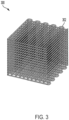
- FIG. 3 shows a schematic of illustrative part 300 defined as a porous network formed from continuous polymer matrix 302.
- continuous polymer matrix 302 contains electrically conductive particles in a suitably distributed state, enhanced piezoresistive behavior may be observed.
- the additive manufacturing process shown in FIG. 1 might be modified to introduce porosity into a printed part (such as illustrative part 300 in FIG. 3 ) for purposes of inducing or increasing piezoresistive behavior therein, doing so may be problematic in various aspects. It may be difficult to introduce fine porosity features with coextruded build and removable support materials, and co-extrusion in this manner may significantly increase the time needed to complete a printing process.
- Printing of a part having porosity defined therein as a regular array may also be accomplished using a single print head depositing a suitable build material, but resolution of the printing process may similarly limit the pores or channels to excessively large sizes, and the printing process may significantly increase in complexity.
- removable supports similar to removable support 114 in FIG. 1 may be introduced, as needed, to facilitate fabrication of the printed part.
- the dissolvable or degradable material (sacrificial material) defining the removable support may comprise the same or different dissolvable or degradable thermoplastic polymer comprising a portion of the as-printed polymer matrix defining the part.
- the dissolvable or degradable polymer in the as-printed polymer matrix defining the part may be removed to define porosity in the printed part under the same or different conditions to those used for eliminating a removable support to define an overhang. Definition of porosity within the printed part and elimination of the removable support may take place in any order, including definition of porosity and elimination of the removable support at substantially the same time.
- composite filaments of the present disclosure may be suitable for use in fused filament fabrication and comprise a continuous polymer phase comprising a first thermoplastic polymer and second thermoplastic polymer that are immiscible with one another, and a plurality of electrically conductive particles distributed in the continuous polymer phase, in which the plurality of electrically conductive particles may comprise microparticles, nanoparticles, or any combination thereof.
- the first thermoplastic polymer may be dissolvable or degradable under specified conditions
- the second thermoplastic polymer may be insoluble or non-degradable under the specified conditions. Examples of dissolvable or degradable thermoplastic polymers, insoluble or non-degradable thermoplastic polymers, and electrically conductive particles are provided hereinafter.
- the continuous polymer phase or the electrically conductive particles may constitute a majority component or a minority component of the composite filaments disclosed herein.
- the electrically conductive particles may be present in the continuous polymer phase at a particle:polymer weight ratio ranging from about 10:90 to about 95:5 or any subrange in between, based on total composite weight with both thermoplastic polymers present. These weight percentages correspond to a particle volume percentage ranging from about 1.2 vol. % to about 68 vol. %. The foregoing volume percentages are likewise based upon total composite volume before removal of one of the thermoplastic polymers and presume a particle density of 10.49 g/cm 3 for Ag particles. Other types of electrically conductive particles may be present in similar volume percentage ranges.
- the weight ratio of electrically conductive particles to continuous polymer phase in the composite filaments may range from about 20:80 (3 vol. % Ag particles) to about 80:20 (62 vol. % Ag particles), or about 30:70 (5 vol. % Ag particles) to about 70:30 (21 vol. % Ag particles), or about 40:60 (7 vol. % Ag particles) to about 60:40 (15 vol. % Ag particles), based on total composite weight with both thermoplastic polymers present.
- the volume percentage range for the electrically conductive particles may range from about 2 vol. % to about 80 vol. %.
- a maximum loading of the electrically conductive particles may be chosen such that the composite filament maintains structural integrity as a continuous filament and remains printable by fused filament fabrication.
- the loading of electrically conductive particles may be selected such that a printed part has desired mechanical properties and/or a desired degree of piezoresistivity following removal of one of the thermoplastic polymers.
- the electrically conductive particles may be distributed within the continuous polymer phase in a manner such that the electrically conductive particles remain substantially dispersed as individuals, both in the composite filament or a printed part obtained therefrom.
- the distribution of the electrically conductive particles in the continuous polymer phase may be substantially uniform in portions of the continuous polymer phase where the electrically conductive particles are present (e.g., a substantially uniform distribution of the electrically conductive particles within the non-degradable or non-dissolvable thermoplastic polymer).
- the ratio of the first thermoplastic polymer to the second thermoplastic polymer may likewise vary over a wide range. In non-limiting examples, a ratio of the first thermoplastic polymer to the second thermoplastic polymer may range from about 1:99 to about 99:1 by weight.
- the ratio of the first thermoplastic polymer to the second thermoplastic polymer may range from about 10:90 to about 90:10, or about 20:80 to about 80:20, or about 30:70 to about 70:30, or about 40:60 to about 60:40, or about 10:90 to about 20:80, or about 20:80 to about 30:70, or about 30:70 to about 40:60, or about 40:60 to about 50:50, or about 50:50 to about 60:40, or about 60:40 to about 70:30, or about 70:30 to about 80:20, or about 80:20 to about 90:10.
- the ratio of the first thermoplastic polymer to the second thermoplastic polymer may be selected such that a desired extent of flexibility is realized once a printed part is formed and the first thermoplastic polymer is removed, or to tailor the extent of porosity formed in the printed part. Similarly, the ratio may be tailored to facilitate formation of the composite filament and/or printing therewith prior to removal of one of the thermoplastic polymers. Based on the degree of porosity formed, the piezoresistive behavior may vary accordingly. Piezoresistive behavior may be observed by a decrease in resistance as a higher mechanical load (weight) is borne by the continuous polymer phase or a printed part formed therefrom. Increased or emergent piezoresistivity may be observed after removal of at least a portion of the first thermoplastic polymer from a printed part.
- the printed parts may have a degree of porosity commensurate with the amount of the first thermoplastic polymer that is removed.
- the printed parts may have a porosity ranging from about 5% to about 80%, or about 10% to about 50%, or about 30% to about 70%, based upon the amount of mass removed relative to the total mass of a printed part prior to removal of the first thermoplastic polymer.
- the pore size or the channel size of interconnected pores may depend upon the extent of dispersion of the first thermoplastic polymer in the continuous polymer phase, as well as the amount of the first thermoplastic polymer that is removed.
- the electrically conductive particles may be present in a printed polymer matrix comprising the second thermoplastic polymer (the remaining thermoplastic polymer) at a particle:polymer mass ratio of about 20:80 to about 97:3, based on total mass of the part following removal of the first thermoplastic polymer.
- the second thermoplastic polymer the remaining thermoplastic polymer
- a particle:polymer mass ratio of about 20:80 to about 97:3, based on total mass of the part following removal of the first thermoplastic polymer.
- Electrically conductive particles suitable for use in any embodiment of the disclosure herein may have an average particle size in a micrometer or nanometer size range, or a combination of micrometer- and nanometer-size electrically conductive particles may be used.
- suitable electrically conductive particles may have a diameter of about 25 microns or less, or about 10 microns or less, such as about 1 micron to about 10 microns, or about 2 microns to about 8 microns.
- Smaller electrically conductive particles such as those having an average particle size of about 100 nm or under or an average particle size of about 500 nm or under, such as average particle size of about 10 nm to about 100 nm, or about 20 nm to about 80 nm, or about 100 nm to about 500 nm, may also be utilized in the disclosure herein, either alone or in combination with larger electrically conductive particles in the micrometer-size range.
- Average particle sizes in the disclosure herein represent D 50 values, which refers to a diameter at which 50% of the sample (on a volume basis unless otherwise specified) is comprised of particles having a diameter less than said diameter.
- D 50 may also be referred to as the "average particle size.”
- average particle size measurements may be made by analysis of optical images, including via SEM analysis, or using onboard software of a Malvern MASTERSIZER 3000 Aero S instrument, which uses light scattering techniques for particle size measurement.
- Electrically conductive particles suitable for use in the disclosure herein may comprise a metal, a carbonaceous conductor, or any combination thereof.
- Metals that may comprise the electrically conductive particles include, but are not limited to, high-conductivity metals such as silver, copper, aluminum, gold, and the like.
- Illustrative forms of electrically conductive particles comprising a metal may include, for example, nanoparticles, nanoflakes, nanowires, nanorods, microflakes, and the like, such as silver nanoparticles, silver nanoflakes, silver microflakes, silver nanowires, silver nanorods, aluminum microflakes, aluminum nanowires, copper microflakes, copper nanoparticles, copper nanowires, gold nanoparticles, the like, or any combination thereof.
- Carbonaceous conductors that may be used alone or in combination with one or more electrically conductive particles comprising a metal may include, but are not limited to, carbon black, carbon fibers, graphene, carbon nanotubes, the like, or any combination thereof.
- the electrically conductive particles may be distributed substantially as individuals in the continuous polymer phase.
- at least a majority of the electrically conductive particles may be located in or otherwise associated with the second thermoplastic polymer in the continuous polymer phase.
- the extent of localization with or association between the electrically conductive particles and the second thermoplastic polymer may be determined based upon the amount of electrically conductive particles lost upon dissolution or degradation of the first thermoplastic polymer when establishing porosity in the disclosure herein.
- At least about 80%, at least about 85%, at least about 90%, or at least about 95% of the electrically conductive particles originally blended with the continuous polymer phase may remain associated with the second thermoplastic polymer once the first thermoplastic polymer has been removed.
- the first thermoplastic polymer may be water-soluble and the second thermoplastic polymer may be water-insoluble.
- water-soluble thermoplastic polymers suitable for use in the disclosure herein may include, for example, polyvinyl alcohol, polyethylene glycol, any copolymer thereof, or any combination thereof.
- suitable first thermoplastic polymers may include, but are not limited, to a polyvinylpyrrolidone, a polyoxazoline (e.g ., poly(2-ethyl-2-oxazoline)), a cellulose ester, a polylactic acid, a polylactate, a polycaprolactone, any copolymer thereof, or any combination thereof.
- Solubility or degradiation in aqueous acid solutions is also included within the scope of water solubility in the disclosure herein.
- Polylactic acid may be effectively degraded through contact with an aqueous acid.
- Polylactic acid may also be used effectively as a build material in the disclosure herein (i.e., as the second thermoplastic polymer). If polylactic acid is used as the second thermoplastic polymer, the specified conditions for dissolving or degrading the first thermoplastic polymer may be chosen so as not to degrade the polylactic acid (i.e ., non-acidic conditions). Similar considerations apply to polyesters like polycaprolactones, which may likewise be degradable under aqueous acid conditions but may be suitably used as a second thermoplastic polymer if the first thermoplastic polymer is removed under conditions that do not promote their degradation.
- thermoplastic polymers may be utilized as the second thermoplastic polymer in the disclosure herein. Any thermoplastic polymer may constitute a suitable second thermoplastic polymer, provided that the second thermoplastic polymer is insoluble and/or non-degradable under the specified conditions at which the first thermoplastic polymer is dissolvable or degradable.
- the second thermoplastic polymer may also be selected based upon printing feasibility and the physical properties of the printed part obtained following removal of the first thermoplastic polymer.
- Suitable thermoplastic polymers usable as the second thermoplastic polymer may exhibit a softening temperature or melting point sufficient to facilitate deposition (printing) at a temperature ranging from about 50°C to about 400°C, or about 70°C to about 275°C, or from about 100°C to about 200°C, or from about 175°C to about 250°C. Melting points may be determined using ASTM E794-06 (2016) with a 10°C ramping and cooling rate, and softening temperatures may be determined using ASTM D6090-17.
- thermoplastic polymers usable as the second thermoplastic polymer in the disclosure herein may include, for instance, a polyamide, a polycaprolactone, a polylactic acid, a poly(styrene-isoprene-styrene) (SIS), a poly(styrene-ethylene-butylene-styrene) (SEBS), a poly(styrene-butylene-styrene) (SBS), a high-impact polystyrene (HIPS), polystyrene, a thermoplastic polyurethane (TPU), a poly(acrylonitrile-butadiene-styrene) (ABS), a polymethylmethacrylate, a poly(vinylpyrrolidine-vinylacetate), a polyester, a polycarbonate, a polyethersulfone, a polyoxymethylene, a polyether ether ketone, a polyetherimide, a polyethylene,
- thermoplastic polymers are water-soluble, they may still be utilized as the second (insoluble and/or non-degradable) thermoplastic polymer if the first (soluble and/or degradable polymer) is removed under nonaqueous conditions (e.g., through dissolution with an organic solvent).
- the second thermoplastic polymer which remains associated with the electrically conductive particles following removal of the first thermoplastic polymer, may itself be an electrically conductive polymer.
- electrically conductive polymers may include, but are not limited to, polyacetylenes, polyanilines, polypyrroles, polythiophenes (including, poly-(3,4-ethylenedioxythiophene), PEDOT), polyphenylenes and other polyarylenes, polyphenylene vinylenes, and the like.
- electrically conductive polymers may also be blended with non-conductive thermoplastic polymers as well.
- the polymer composites and composite filaments of the present disclosure may be substantially free of thermosetting polymers, including uv-curable resins and similar resins capable of forming thermosetting polymers.
- the composites of the present disclosure may be obtained under aqueous processing conditions to afford electrically conductive particles distributed in a continuous polymer matrix comprising the first thermoplastic polymer and the second thermoplastic polymer.
- the composites may be obtained in the form of a film before subsequently being processed into a composite filament.
- the composites may be processed into a composite filament (e.g ., through extrusion) suitable for conducting fused filament fabrication, processed into a larger composite fiber or filament, converted into pellets, and/or used directly in the form of a shredded or pulverized composite film ( e.g ., composite pieces).
- Suitable extrusion conditions may take place above the melting point or softening temperature of the continuous polymer matrix with a single- or twin-screw extruder, for example.
- electrically conductive particles may be combined with an aqueous dispersion of the second thermoplastic polymer. Thereafter, the first thermoplastic polymer (e.g ., a water-soluble polymer) may be added to the aqueous dispersion. Water may be evaporated to form a composite film, which may then be extruded into a filament.
- the first thermoplastic polymer e.g ., a water-soluble polymer
- electrically conductive particles may be combined with an aqueous dispersion of the second thermoplastic polymer. Thereafter, the water may be evaporated, and the first thermoplastic polymer (e.g ., a water-soluble polymer) may be combined with the residue, which may then be blended together to form the composite. A composite filament may then be obtained by extrusion thereafter.
- first thermoplastic polymer e.g ., a water-soluble polymer
- methods for forming a composite according to the disclosure herein may comprise combining a plurality of electrically conductive particles and a first thermoplastic polymer that is water-soluble (or alternately degradable under specified conditions) with an aqueous dispersion of a second thermoplastic polymer that is water-insoluble (or alternately non-degradable under the specified conditions at which the first thermoplastic polymer is dissolvable or degradable) to provide a combined aqueous mixture; and removing water from the combined aqueous mixture to provide a composite residue comprising at least a portion of the electrically conductive particles distributed in a continuous polymer phase comprising the first thermoplastic polymer and the second thermoplastic polymer, in which the first thermoplastic polymer and the second thermoplastic polymer may remain immiscible with one another in the continuous polymer phase.
- the first thermoplastic polymer may be at least partially replaced with dissolvable or degradable particles that may undergo separation or removal from the second thermoplastic polymer under specified conditions.
- Liquids that are removal under specified conditions may similarly at least partially replace the first thermoplastic polymer, provided that a blend of the liquid, the second thermoplastic polymer, and the conductive particles retains the capability for being processed into a continuous filament according to the disclosure herein.
- Dissolvable or degradable particles or liquids may undergo degradation or removal under similar conditions to those used for promoting degradation or removal of the first thermoplastic polymer.
- dissolvable or degradable particles or liquids may be water-soluble
- the second thermoplastic polymer may be water-insoluble under specified conditions.
- gas-forming substances may be utilized to introduce porosity in a continuous polymer matrix comprising the second thermoplastic polymer.
- the first thermoplastic polymer may be at least partially replaced with the gas-forming substance (e.g., microspheres containing a gas or a material that degrades to a gas under specified conditions) and combined with the second thermoplastic polymer. Formation of gas within the second thermoplastic polymer may result in bubble formation and definition of porosity therein once processing takes place under suitable conditions.
- the composite residue may be utilized directly in the form of shreds or a pulverized film (e.g., when the combined aqueous mixture is cast as a composite film and water is evaporated therefrom).
- the composite residue may be extruded into a composite filament suitable for fused filament fabrication or a composite fiber having an even larger diameter, in which the electrically conductive particles are distributed in the continuous polymer phase.
- a larger composite fiber may be cut or similarly processed into composite pellets having the electrically conductive particles similarly distributed in the continuous polymer phase.
- the composite film may be broken up (e.g., by shredding or pulverizing) after evaporating water therefrom into a plurality of composite pieces, and extruding the composite pieces to form a composite filament.
- the composite or the composite filament obtained in accordance with foregoing may be processed to remove at least a portion of the first thermoplastic polymer therefrom, thereby defining porosity in the continuous polymer phase.
- Such composite filaments may comprise the second thermoplastic polymer defined as a porous polymer network with the electrically conductive particles distributed therein.
- pores or channels within the porous polymer network may be backfilled with one or more additives to modify the composite properties still further, such as additional electrically conductive particles, thermally conductive particles, reinforcement fibers, colorants, stabilizers, plasticizers, and the like.
- additives may be introduced in a liquid solution or dispersion, which is subsequently evaporated once backfilling has taken place.
- the composite filaments may be deposited layer-by-layer above a softening temperature thereof to form a printed part having a specified shape.
- the printed part may comprise a continuous polymer matrix comprising the first thermoplastic polymer and the second thermoplastic polymer that remain immiscible with one another, and a plurality of electrically conductive particles distributed in the continuous printed polymer matrix.
- At least a majority of the electrically conductive particles may be substantially located in or associated with the second thermoplastic polymer, such that the first thermoplastic polymer may be removed from the printed part through dissolution or degradation (e.g., through water-solubility) without also removing a significant fraction of the electrically conductive particles.
- a printed part having porosity defined therein may be obtained.
- such printed parts may exhibit piezoresistivity and comprise a printed polymer matrix having porosity defined therein and comprising a plurality of electrically conductive particles distributed in a thermoplastic polymer (e.g., the second thermoplastic polymer remaining after dissolution or degradation of the first thermoplastic polymer).
- Suitable types of printed parts having piezoresistive behavior are not considered to be particularly limited in the present disclosure.
- the resulting porosity in a printed part may be backfilled with one or more additional additives.
- backfilling may take place in a similar manner to that described above in regard to backfilling a porous composite filament.
- exemplary combinations applicable to A-E include, but are not limited to: 1, and 2 or 2A; 1 and 3; 1 and 4; 1 and 5; 1 and 6; 1 and 7; 1 and 8; 2 or 2A, and 3; 2-4; 2A, 3 and 4; 2 or 2A, 3 and 5; 2 or 2A, 3 and 6; 2 or 2A, 3 and 7; 2 or 2A, 3 and 8; 3 and 4; 3 and 5; 3 and 6; 3 and 7; 3 and 8; 4 and 5; 4 and 6; 4 and 7; 4 and 8; 5 and 6; 5 and 7; 5 and 8; 6 or 7, and 8; any of 1-8, and 9; any of 1-9, and 10; any of 1-10, and 11; 10 and 11; and any of 1-11, and 12.
- Composite Film Formation The following general procedure was utilized to prepare composite films that may be further processed into composite filaments. Silver microflakes were combined with an aqueous polymer dispersion, and the aqueous polymer dispersion was combined with a solution of a water-soluble polymer. The resulting combined aqueous mixture was cast as a film, and the water was evaporated. The resulting composite residue was analyzed, and optionally ground and extruded into a composite filament.
- Silver microflakes ( ⁇ 2-4 ⁇ m) were purchased from Inframat Advanced Materials, LLC.
- Thermoplastic Polyurethane (TPU) emulsions (Alberdingk U 615) were purchased from Alberdingk Boley Inc.
- Polyvinyl Alcohol (PVA, SELVOL TM E 203 S, a low viscosity partially hydrolysed polyvinyl alcohol) was purchased from Sekisui Specialty Chemicals.
- Polyethylene glycol) (PEG) having an average molecular weight (Mn) of 35,000 was purchased from Sigma-Aldrich, Inc.
- Example 1 Base Piezoresistive Formulation without Water-Soluble Polymer.
- One gram of silver microflakes were combined with 1.25 g of TPU emulsion, and the resulting mixture was rolled on a movil rod roller for 4 hours to mix thoroughly. Films were cast by pouring the mixture into trays. Water from the mixture was evaporated under ambient conditions in a fume hood, under vacuum overnight, or in an oven at 60°C for 2 hours. After drying, the mass ratio of silver microflakes to TPU was 2:1.
- Example 2 Piezoresistive Formulation with PVA.
- Example 1 was repeated, except 1.0 g of a 25 wt. % solution of PVA was combined with the mixture of silver microflakes and TPU. After drying, the mass ratio of silver microflakes to TPU to PVA was 4:2:1.
- processing was conducted by mixing 180 g of silver microflakes with 225 g Alberdink U 615 TPU emulsion (90 g TPU solids), and rolling the mixture on a movil rod roller for 4 hours. Films were cast by pouring the rolled mixture onto trays and removing the water under ambient conditions, under reduced pressure, or in an oven at 60°C for 2 hours. The dried material was ground into small pieces and further dried overnight at 40°C under reduced pressure. 90 g of the further dried material (representing 60 g silver microflakes and 30 g TPU) was combined with 15 g PVA and compounded at 180°C in a Haake mixer. Filaments were successfully extruded from the material produced under scale up conditions.
- Example 3 Sonicated Film of Example 2. The dried film of Example 2 was sonicated in water for 3 hours to remove the PVA. Sonication was conducted with a Branson 1510 ultrasonic bath.
- Example 4 Piezoresistive Formulation with PEG.
- Example 1 was repeated, except 0.25 g of a 40 wt. % solution of PEG was combined with the mixture of silver microflakes and TPU. After drying, the mass ratio of silver microflakes to TPU to PEG was 4:2:1.
- Example 2 The scale up synthesis of Example 2 was conducted, except substituting PEG for PVA. After compounding, the resulting mixture had a mass ratio of silver microflakes to TPU to PEG of 4:2:1. Filaments were successfully extruded from the material produced under scale up conditions.
- Example 5 Sonicated Film of Example 4. The dried film of Example 4 was sonicated 3 hours to remove the PVA. Sonication was conducted with a Branson 1510 ultrasonic bath.
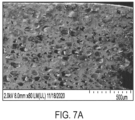
- Example 1 The product from Example 1 was analyzed by scanning electron microscopy (SEM). Cross-sectional SEM images showed a good distribution of the silver microflakes in the composite matrix. The SEM images are shown in FIGS. 7A and 7B and are discussed below in reference to composite filaments prepared therefrom.
- the discrepancy between the silver content for the films of Examples 1, 2 and 4 is believed to arise from retention of water in the composite films.
- the film of Example 1 was not dried under vacuum prior to analysis, which may account for its higher than expected water content, even though this film did not contain a water-soluble polymer.
- the experimental silver content was very close to that predicted by theory (samples of Examples 3 and 5). The close correlation to theory indicates that PVA and PEG were effectively removed by sonication, and very little silver was dispersed in the water-soluble phase (PVA or PEG) of the two immiscible polymers.
- the composite films of Examples 1-5 were qualitatively assessed for their flexibility and brittleness by manually bending the films by hand.
- the composite film of Example 1 cracked directly upon folding.
- the composite film of Example 2 was highly brittle, but after removing PVA (Example 3), the film was much more flexible and could be folded in half without cracking and breaking. Comparing Examples 4 and 5, the composite film was considerably more flexible after removing PEG (Example 5).
- the PEG system (Example 4) was not as rigid as the PVA system (Example 2).
- the piezoresistive performance of the composite films of Examples 1-5 was assessed by measuring the change in resistance with varying applied pressures.
- Composite films for piezoresistive measurements were prepared by drying in an oven at 60°C for 2 hours to afford a 0.8 mm film thickness. Resistance was measured using a multimeter connected to the composite. The resistance was measured at five different weights applied to the composite film: 72 g, 122 g, 272 g, 572 g, and 1072 g.
- An aluminum plaque (72 g) was placed on the film as a top electrode to better distribute applied force upon the composite and to provide a consistent contact area. Additional weights were added to the aluminum plaque to reach the indicated total weights.
- Example 4 shows a plot of resistance as a function of weight applied to the film of Examples 1-5. All the composite films showed a decrease in resistance with increased applied weight (load). The composite film lacking PVA or PEG (Example 1) tended to show lower initial resistance than did the other films, especially in the lower applied pressure range. At the lowest applied pressure, the composite film containing PVA (Example 2) had a statistically significant 14.3% higher resistance than did the comparable film containing PEG (Example 4). After removal of the PVA or PEG, the resistance values were much closer to one another (Examples 3 and 5), but still much higher than that of TPU alone (Example 1) at the lowest applied pressures. The composite films comprising PVA/PEG showed higher initial resistance values than the ones without, and higher sensitivity in the lower pressure range ( i.e., the lower weights). As the pressure increased, the resistance values became less distinguishable from one another.
- the composite films prepared as above were further processed into composite filaments using a Filabot EX6 filament extruder.
- the extruder consists of an extruder, an air path, and a filament winder.
- the extruder has four zones of heating: i) a feed port nozzle, ii) a back zone, iii) a middle zone, and iv) a front zone.
- the extruder was modified with a digital voltage readout for controlling the motor speed of the extrusion screw and therefore the extrusion speed.
- the feed path nozzle can be interchanged with nozzles of different diameters.
- the air path can be adjusted for airflow.
- the position of the air path can be adjusted with respect to the distance from an outlet nozzle, or by raising the air path on a jack.
- the height of the air path was kept constant in this experiment.
- the distance of the air path from the outlet nozzle was also varied to maintain a constant filament diameter.
- Table 2 summarizes the filament extrusion conditions used to prepare the composite filaments of Examples 6 and 7 (see below). The filament diameter was measured using an inline thickness gauge.
- Example 7 Feed Temperature (°C) 40 30 Back Temp (°C) 165 120 Middle Temp (°C) 165 125 Front Temp (°C) 165 125 Voltage (V) 7.7 10.0 Current (A) 0.651 2.2 Nozzle size (mm) 1.75 2 Air flow 90% 100% Winding speed (rpm) 0.95 0.9 Average filament diameter (mm) 1.6 1.7
- Example 6 Piezoresistive Filament Lacking a Water-Soluble Polymer.
- the composite film of Example 1 was prepared at 100 times the previous scale, ground into pieces and dried under vacuum for 2 hours. The ground material was then extruded into filaments as specified in Table 2.
- FIG. 5A shows a photograph of the composite filament of Example 6.
- Example 7 Piezoresistive Filament Containing PVA.
- the composite film of Example 2 was prepared at 100 times the previous scale, ground into pieces and dried under vacuum for 2 hours. The ground material was then extruded into filaments as specified in Table 2.
- FIG. 5B shows a photograph of the composite filament of Example 7.
- the as-produced composite filament had an average density of 2.63 g/cm 3 , as measured by gas pycnometry using a Micromeritics ACCYPYC 1330 instrument.
- Example 8 Sonicated Piezoresistive Filament of Example 7.
- the composite filament of Example 7 was sonicated in water for 3 hours, soaked in water for 24 hours, and then dried under vacuum oven to remove the PVA. Sonication was conducted with a Branson 1510 ultrasonic bath.
- the sonicated composite filament had an average density, as measured by gas pycnometry, of 2.97 g/cm 3 .
- the gas pycnometry-measured density increase is consistent with at least partial removal of PVA from the composite filaments and formation of porosity therein.
- FIG. 6 shows a plot of resistance as a function of weight applied to the composite filament of Example 8. As shown, the resistance decreased from 12.2 MS2 to 2.4 MS2 as the applied weight was increased.
- piezoresistive composites may be obtained from the composite filaments after removal of the PVA.
- FIGS. 7A and 7B show SEM images of a silver microflake/TPU composite film (Example 1) at two different magnifications. As shown, the silver microflakes were dispersed mostly uniformly in the polymer matrix, with a few regions of non-uniform dispersion and porosity being present. The porosity of the film may account for its piezoresistive behavior.
- FIGS. 8A and 8B show cross-sectional SEM images of a silver microflake/TPU composite filament (Example 6) at two different magnifications. Compared to the corresponding film ( FIGS. 7A and 7B ), the silver microflakes were more uniformly dispersed and more densely packed in the filament. In contrast to the porous films, porosity was not evident in the filament. The lack of porosity and dense silver microflake packing may account for the lack of electrical conductivity.
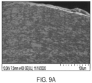
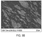
- FIGS. 9A and 9B , and FIGS. 9C and 9D show cross-sectional SEM images of composite filaments of Examples 7 and 8, respectively, (before and after PVA removal) at two magnifications.
- the composite filament of Example 7 showed uniform silver microflake distribution and dense packing, indicating that addition of PVA did not disrupt particle dispersion. Porosity was evident in the composite filament of Example 8, which may account for its electrical conductivity and piezoresistive effect.
- Example 7 The composite filament of Example 7 was printed as single- and multi-layer 2 cm x 2 cm square coupons using a Hyrel HYDRA 16A 3D printer employing a HT2-250 extruder print head. Each printed layer was approximately 200 microns in thickness. A five-layer coupon was chosen as an illustrative sample for further evaluation described below. Extrusion was conducted at an extrusion rate of 10 mm/s at 170°C onto a glass plate held at 45°C.
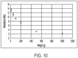
- the as-printed coupon was non-conductive. After sonication of the as-printed coupon to remove PVA, the resulting porous coupon was electrically conductive both upon its surface and through its cross-sectional thickness. Resistance was then measured across the cross-sectional thickness using applied weights of 10, 50, 100, 200, 500 and 1000 g.
- FIG. 10 shows a plot of resistance versus applied pressure. As shown, the resistance decreased gradually with increasing pressure.
- compositions described herein may be free of any component, or composition not expressly recited or disclosed herein. Any method may lack any step not recited or disclosed herein.
- compositions, element or group of elements are preceded with the transitional phrase “comprising,” it is understood that we also contemplate the same composition or group of elements with transitional phrases “consisting essentially of,” “consisting of,” “selected from the group of consisting of,” or “is” preceding the recitation of the composition, element, or elements and vice versa.
Landscapes
- Chemical & Material Sciences (AREA)
- Engineering & Computer Science (AREA)
- Materials Engineering (AREA)
- Manufacturing & Machinery (AREA)
- Mechanical Engineering (AREA)
- Chemical Kinetics & Catalysis (AREA)
- General Chemical & Material Sciences (AREA)
- Textile Engineering (AREA)
- Optics & Photonics (AREA)
- Physics & Mathematics (AREA)
- Life Sciences & Earth Sciences (AREA)
- Organic Chemistry (AREA)
- Wood Science & Technology (AREA)
- Composite Materials (AREA)
- Structural Engineering (AREA)
- Civil Engineering (AREA)
- Ceramic Engineering (AREA)
- Compositions Of Macromolecular Compounds (AREA)
- Extrusion Moulding Of Plastics Or The Like (AREA)
Applications Claiming Priority (1)
| Application Number | Priority Date | Filing Date | Title |
|---|---|---|---|
| US17/701,364 US12319826B2 (en) | 2022-03-22 | 2022-03-22 | Piezoresistive composites via additive manufacturing and composite filaments associated therewith |
Publications (2)
| Publication Number | Publication Date |
|---|---|
| EP4249256A2 true EP4249256A2 (fr) | 2023-09-27 |
| EP4249256A3 EP4249256A3 (fr) | 2023-10-18 |
Family
ID=85415170
Family Applications (1)
| Application Number | Title | Priority Date | Filing Date |
|---|---|---|---|
| EP23159602.4A Pending EP4249256A3 (fr) | 2022-03-22 | 2023-03-02 | Composites piézorésistifs par fabrication additive et filaments composites associés à ceux-ci |
Country Status (6)
| Country | Link |
|---|---|
| US (1) | US12319826B2 (fr) |
| EP (1) | EP4249256A3 (fr) |
| JP (1) | JP2023140312A (fr) |
| KR (1) | KR20230140477A (fr) |
| CN (1) | CN116791235A (fr) |
| CA (1) | CA3193546A1 (fr) |
Families Citing this family (2)
| Publication number | Priority date | Publication date | Assignee | Title |
|---|---|---|---|---|
| US20240165852A1 (en) * | 2022-05-06 | 2024-05-23 | Purdue Research Foundation | Three-dimensional printing processes, fused deposition modeling (fdm) materials, filaments, and inks, and associated methods |
| WO2025109677A1 (fr) * | 2023-11-21 | 2025-05-30 | 日本電信電話株式会社 | Imprimante tridimensionnelle, procédé d'impression tridimensionnelle et programme |
Family Cites Families (9)
| Publication number | Priority date | Publication date | Assignee | Title |
|---|---|---|---|---|
| CN101249410B (zh) * | 2008-04-10 | 2011-05-11 | 华东理工大学 | 一种有机—无机复合微球的制备方法 |
| FR2975708B1 (fr) | 2011-05-23 | 2014-07-18 | Arkema France | Fibres composites conductrices comprenant des charges conductrices carbonees et un polymere conducteur |
| US10744695B2 (en) | 2018-01-18 | 2020-08-18 | Battelle Memorial Institute | Polymer composites for fused filament fabrication and methods of making the same |
| CN109785995B (zh) * | 2018-12-07 | 2021-07-13 | 深圳大学 | 一种用于制备柔性压阻式传感器的多孔导电浆料及其制备方法和应用 |
| US12338552B2 (en) | 2018-12-21 | 2025-06-24 | Kuraray Co., Ltd. | Composite fiber |
| CN110823421A (zh) * | 2019-11-18 | 2020-02-21 | 西南石油大学 | 一种利用3d打印制备柔性压阻式剪切力传感器的方法 |
| CN113073426B (zh) * | 2021-02-25 | 2022-05-31 | 东华大学 | 多孔多中空柔性复合纳米纤维膜材料及其制备方法 |
| CN113683858A (zh) * | 2021-07-13 | 2021-11-23 | 浙江工业大学 | 一种高机械强度的导电3d打印石墨烯复合材料的制备方法 |
| EP4184529A1 (fr) | 2021-11-23 | 2023-05-24 | Karlsruher Institut für Technologie | Filament hautement conducteur de modelage par dépôt en fusion |
-
2022
- 2022-03-22 US US17/701,364 patent/US12319826B2/en active Active
-
2023
- 2023-03-02 EP EP23159602.4A patent/EP4249256A3/fr active Pending
- 2023-03-13 CN CN202310234258.7A patent/CN116791235A/zh active Pending
- 2023-03-13 JP JP2023038209A patent/JP2023140312A/ja active Pending
- 2023-03-15 KR KR1020230033715A patent/KR20230140477A/ko active Pending
- 2023-03-20 CA CA3193546A patent/CA3193546A1/fr active Pending
Also Published As
| Publication number | Publication date |
|---|---|
| US20230323146A1 (en) | 2023-10-12 |
| CN116791235A (zh) | 2023-09-22 |
| EP4249256A3 (fr) | 2023-10-18 |
| CA3193546A1 (fr) | 2023-09-22 |
| US12319826B2 (en) | 2025-06-03 |
| KR20230140477A (ko) | 2023-10-06 |
| JP2023140312A (ja) | 2023-10-04 |
Similar Documents
| Publication | Publication Date | Title |
|---|---|---|
| Sezer et al. | FDM 3D printing of MWCNT re-inforced ABS nano-composite parts with enhanced mechanical and electrical properties | |
| Isobe et al. | Comparison of strength of 3D printing objects using short fiber and continuous long fiber | |
| EP4249256A2 (fr) | Composites piézorésistifs par fabrication additive et filaments composites associés à ceux-ci | |
| EP3475958B1 (fr) | Corps moulé électriquement conducteur à coefficient de température positif | |
| AU2014302635B2 (en) | Printed three-dimensional (3D) functional part and method of making | |
| EP4315439A1 (fr) | Composites piézoélectriques contenant un matériau sacrificiel et leur utilisation dans la fabrication additive | |
| US7481952B2 (en) | Electrically conductive PTFE tape | |
| JP2017095694A (ja) | 高導電性コンポジットのための3相の不混和性ポリマー−金属ブレンド | |
| Karimi et al. | Development of highly filled nickel-polymer feedstock from recycled and biodegradable resources for low-cost material extrusion additive manufacturing of metals | |
| AU2018217234B2 (en) | Carbon nanotube enhanced polymers and methods for manufacturing the same | |
| KR102641155B1 (ko) | 금속-나노탄소 복합 입자를 포함하는 3d 프린팅용 압저항 조성물, 이를 이용하여 제조된 압저항 복합체 및 이의 제조방법 | |
| Mohammadi et al. | Additive manufacturing of recyclable, highly conductive, and structurally robust graphite structures | |
| US20200207983A1 (en) | Composite material and its use in additive manufacturing methods | |
| WO2022229962A1 (fr) | Compositions extrudables comprenant des particules polymères revêtues de nanotubes de carbone | |
| Shanmugam et al. | 3D printing of nanocomposites | |
| Sukati et al. | Additive Manufacturing of Controlled Porous Elastomeric Nanocomposites for Enhanced Sensing Function | |
| Shanmugam et al. | 3D Printing | |
| KR20210040952A (ko) | 분말의 제조 방법, 용융 성형체의 제조 방법, 분말, 압축 성형체 및 용융 성형체 | |
| Mohammadi et al. | Additive manufacturing of recyclable, highly conductive, and structurally robust graphite structures |
Legal Events
| Date | Code | Title | Description |
|---|---|---|---|
| PUAI | Public reference made under article 153(3) epc to a published international application that has entered the european phase |
Free format text: ORIGINAL CODE: 0009012 |
|
| STAA | Information on the status of an ep patent application or granted ep patent |
Free format text: STATUS: THE APPLICATION HAS BEEN PUBLISHED |
|
| PUAL | Search report despatched |
Free format text: ORIGINAL CODE: 0009013 |
|
| AK | Designated contracting states |
Kind code of ref document: A2 Designated state(s): AL AT BE BG CH CY CZ DE DK EE ES FI FR GB GR HR HU IE IS IT LI LT LU LV MC ME MK MT NL NO PL PT RO RS SE SI SK SM TR |
|
| AK | Designated contracting states |
Kind code of ref document: A3 Designated state(s): AL AT BE BG CH CY CZ DE DK EE ES FI FR GB GR HR HU IE IS IT LI LT LU LV MC ME MK MT NL NO PL PT RO RS SE SI SK SM TR |
|
| RIC1 | Information provided on ipc code assigned before grant |
Ipc: D01F 6/94 20060101ALI20230913BHEP Ipc: D01F 6/70 20060101ALI20230913BHEP Ipc: D01D 5/247 20060101ALI20230913BHEP Ipc: B29C 64/118 20170101ALI20230913BHEP Ipc: D01F 6/50 20060101ALI20230913BHEP Ipc: D01F 1/09 20060101ALI20230913BHEP Ipc: B33Y 70/10 20200101AFI20230913BHEP |
|
| STAA | Information on the status of an ep patent application or granted ep patent |
Free format text: STATUS: REQUEST FOR EXAMINATION WAS MADE |
|
| 17P | Request for examination filed |
Effective date: 20240418 |
|
| RBV | Designated contracting states (corrected) |
Designated state(s): AL AT BE BG CH CY CZ DE DK EE ES FI FR GB GR HR HU IE IS IT LI LT LU LV MC ME MK MT NL NO PL PT RO RS SE SI SK SM TR |