EP4249330A1 - Connecteur d'essuie-glace, ensemble balai d'essuie-glace et dispositif d'essuie-glace - Google Patents
Connecteur d'essuie-glace, ensemble balai d'essuie-glace et dispositif d'essuie-glace Download PDFInfo
- Publication number
- EP4249330A1 EP4249330A1 EP23162086.5A EP23162086A EP4249330A1 EP 4249330 A1 EP4249330 A1 EP 4249330A1 EP 23162086 A EP23162086 A EP 23162086A EP 4249330 A1 EP4249330 A1 EP 4249330A1
- Authority
- EP
- European Patent Office
- Prior art keywords
- wiper
- fastener
- wiper arm
- connector
- state
- Prior art date
- Legal status (The legal status is an assumption and is not a legal conclusion. Google has not performed a legal analysis and makes no representation as to the accuracy of the status listed.)
- Granted
Links
Images




Classifications
-
- B—PERFORMING OPERATIONS; TRANSPORTING
- B60—VEHICLES IN GENERAL
- B60S—SERVICING, CLEANING, REPAIRING, SUPPORTING, LIFTING, OR MANOEUVRING OF VEHICLES, NOT OTHERWISE PROVIDED FOR
- B60S1/00—Cleaning of vehicles
- B60S1/02—Cleaning windscreens, windows or optical devices
- B60S1/04—Wipers or the like, e.g. scrapers
- B60S1/32—Wipers or the like, e.g. scrapers characterised by constructional features of wiper blade arms or blades
- B60S1/38—Wiper blades
- B60S1/3848—Flat-type wiper blade, i.e. without harness
- B60S1/3849—Connectors therefor; Connection to wiper arm; Attached to blade
-
- B—PERFORMING OPERATIONS; TRANSPORTING
- B60—VEHICLES IN GENERAL
- B60S—SERVICING, CLEANING, REPAIRING, SUPPORTING, LIFTING, OR MANOEUVRING OF VEHICLES, NOT OTHERWISE PROVIDED FOR
- B60S1/00—Cleaning of vehicles
- B60S1/02—Cleaning windscreens, windows or optical devices
- B60S1/04—Wipers or the like, e.g. scrapers
- B60S1/32—Wipers or the like, e.g. scrapers characterised by constructional features of wiper blade arms or blades
- B60S1/40—Connections between blades and arms
- B60S1/4038—Connections between blades and arms for arms provided with a channel-shaped end
- B60S1/4045—Connections between blades and arms for arms provided with a channel-shaped end comprising a detachable intermediate element mounted on the channel-shaped end
- B60S1/4048—Connections between blades and arms for arms provided with a channel-shaped end comprising a detachable intermediate element mounted on the channel-shaped end the element being provided with retention means co-operating with the channel-shaped end of the arm
-
- B—PERFORMING OPERATIONS; TRANSPORTING
- B60—VEHICLES IN GENERAL
- B60S—SERVICING, CLEANING, REPAIRING, SUPPORTING, LIFTING, OR MANOEUVRING OF VEHICLES, NOT OTHERWISE PROVIDED FOR
- B60S1/00—Cleaning of vehicles
- B60S1/02—Cleaning windscreens, windows or optical devices
- B60S1/04—Wipers or the like, e.g. scrapers
- B60S1/32—Wipers or the like, e.g. scrapers characterised by constructional features of wiper blade arms or blades
- B60S1/34—Wiper arms; Mountings therefor
- B60S1/3415—Wiper arms; Mountings therefor with means for supplying cleaning fluid to windscreen cleaners, e.g. washers
-
- B—PERFORMING OPERATIONS; TRANSPORTING
- B60—VEHICLES IN GENERAL
- B60S—SERVICING, CLEANING, REPAIRING, SUPPORTING, LIFTING, OR MANOEUVRING OF VEHICLES, NOT OTHERWISE PROVIDED FOR
- B60S1/00—Cleaning of vehicles
- B60S1/02—Cleaning windscreens, windows or optical devices
- B60S1/04—Wipers or the like, e.g. scrapers
- B60S1/32—Wipers or the like, e.g. scrapers characterised by constructional features of wiper blade arms or blades
- B60S1/40—Connections between blades and arms
-
- B—PERFORMING OPERATIONS; TRANSPORTING
- B60—VEHICLES IN GENERAL
- B60S—SERVICING, CLEANING, REPAIRING, SUPPORTING, LIFTING, OR MANOEUVRING OF VEHICLES, NOT OTHERWISE PROVIDED FOR
- B60S1/00—Cleaning of vehicles
- B60S1/02—Cleaning windscreens, windows or optical devices
- B60S1/04—Wipers or the like, e.g. scrapers
- B60S1/32—Wipers or the like, e.g. scrapers characterised by constructional features of wiper blade arms or blades
- B60S1/40—Connections between blades and arms
- B60S1/4038—Connections between blades and arms for arms provided with a channel-shaped end
- B60S1/4045—Connections between blades and arms for arms provided with a channel-shaped end comprising a detachable intermediate element mounted on the channel-shaped end
-
- B—PERFORMING OPERATIONS; TRANSPORTING
- B60—VEHICLES IN GENERAL
- B60S—SERVICING, CLEANING, REPAIRING, SUPPORTING, LIFTING, OR MANOEUVRING OF VEHICLES, NOT OTHERWISE PROVIDED FOR
- B60S1/00—Cleaning of vehicles
- B60S1/02—Cleaning windscreens, windows or optical devices
- B60S1/46—Cleaning windscreens, windows or optical devices using liquid; Windscreen washers
- B60S1/48—Liquid supply therefor
- B60S1/52—Arrangement of nozzles; Liquid spreading means
- B60S1/522—Arrangement of nozzles; Liquid spreading means moving liquid spreading means, e.g. arranged in wiper arms
-
- B—PERFORMING OPERATIONS; TRANSPORTING
- B60—VEHICLES IN GENERAL
- B60S—SERVICING, CLEANING, REPAIRING, SUPPORTING, LIFTING, OR MANOEUVRING OF VEHICLES, NOT OTHERWISE PROVIDED FOR
- B60S1/00—Cleaning of vehicles
- B60S1/02—Cleaning windscreens, windows or optical devices
- B60S1/04—Wipers or the like, e.g. scrapers
- B60S1/32—Wipers or the like, e.g. scrapers characterised by constructional features of wiper blade arms or blades
- B60S1/40—Connections between blades and arms
- B60S1/4038—Connections between blades and arms for arms provided with a channel-shaped end
- B60S1/4045—Connections between blades and arms for arms provided with a channel-shaped end comprising a detachable intermediate element mounted on the channel-shaped end
- B60S1/4048—Connections between blades and arms for arms provided with a channel-shaped end comprising a detachable intermediate element mounted on the channel-shaped end the element being provided with retention means co-operating with the channel-shaped end of the arm
- B60S2001/4051—Connections between blades and arms for arms provided with a channel-shaped end comprising a detachable intermediate element mounted on the channel-shaped end the element being provided with retention means co-operating with the channel-shaped end of the arm the intermediate element engaging the side walls of the arm
-
- B—PERFORMING OPERATIONS; TRANSPORTING
- B60—VEHICLES IN GENERAL
- B60S—SERVICING, CLEANING, REPAIRING, SUPPORTING, LIFTING, OR MANOEUVRING OF VEHICLES, NOT OTHERWISE PROVIDED FOR
- B60S1/00—Cleaning of vehicles
- B60S1/02—Cleaning windscreens, windows or optical devices
- B60S1/04—Wipers or the like, e.g. scrapers
- B60S1/32—Wipers or the like, e.g. scrapers characterised by constructional features of wiper blade arms or blades
- B60S1/40—Connections between blades and arms
- B60S1/4038—Connections between blades and arms for arms provided with a channel-shaped end
- B60S1/4045—Connections between blades and arms for arms provided with a channel-shaped end comprising a detachable intermediate element mounted on the channel-shaped end
- B60S1/4048—Connections between blades and arms for arms provided with a channel-shaped end comprising a detachable intermediate element mounted on the channel-shaped end the element being provided with retention means co-operating with the channel-shaped end of the arm
- B60S2001/4054—Connections between blades and arms for arms provided with a channel-shaped end comprising a detachable intermediate element mounted on the channel-shaped end the element being provided with retention means co-operating with the channel-shaped end of the arm the intermediate element engaging the back part of the arm
Definitions
- the present disclosure relates to a wiper connector, a wiper blade assembly, and a wiper device.
- wiper devices are installed in a vehicle or the like to wipe a surface of a windshield.
- a wiper device includes a wiper motor, a wiper arm, a wiper blade, etc., and an adapter may be used for structural connection between the wiper arm and the wiper blade.
- Such a wiper arm has a base end connected to a rotational shaft of the wiper motor and rotated reciprocally by the wiper motor, one or more wiper arms are provided according to a size of the windshield, and when a plurality of wiper arms are provided, the plurality of wiper arms are provided so that the rotations thereof are not interfered with each other.
- the wiper blade is detachably coupled to an end of the wiper arm through an adapter.
- the wiper blade is provided in a straight shape and slides and wipes a surface of the windshield by the movement of the rotating wiper arm while maintaining a state of being in close contact with the windshield.
- Such a wiper blade is continuously rubbing the windshield in a state of being installed in a vehicle and thus may be worn over a period of use, may generate unnecessary noise, or may degrade surface wiping performance. Therefore, the wiper blade needs periodic replacement.
- the user of the vehicle separates a current wiper blade from the wiper arm and then fastens a new wiper blade thereto, and in this case, an adapter having a detachable structure is used between the wiper arm and the wiper blade.
- the adapter has various shapes depending on the type of wiper arm, and recently, since a type of wiper arm in which a nozzle for spraying a washing liquid to wash the windshield is integrated into the wiper arm is used, the development for the adapter that may be efficiently detached from such the type of wiper arm is urgently required.
- the present disclosure is directed to providing a wiper connector, a wiper blade assembly, and a wiper device, which are provided with an adapter capable of being easily detached from a wiper arm equipped with a nozzle for spraying a washing liquid, thereby significantly increasing a user's convenience.
- a wiper connector for mutually connecting a wiper blade and a wiper arm includes an insertion portion inserted into the wiper arm and disposed at one side of a washing liquid spray nozzle provided on the wiper arm, and a fixing portion integrally provided with the insertion portion and fixed to the wiper blade, wherein the insertion portion includes a first fastener caught by a hole provided in an upper surface of the wiper arm, and a second fastener caught by a rib provided inside the wiper arm, and the second fastener is provided to be elastically deformed and provided to be switched from a first state in which the first fastener is elastically deformed by the rib when passing through the hole to a second state in which the first fastener passes the rib and is restored to an original state when being caught by the hole.
- the first fastener may have a hook shape in which an upper end has relatively greater area than a lower end and may be switched between the first state in which the upper end passes through the hole and the second state in which the lower end moves in the hole and at least a part of the upper end is misaligned with the hole.
- the upper end of the first fastener may face the upper surface of the wiper arm to limit movement of the wiper arm in a height direction.
- the second fastener may have a cantilever shape, and have a pressing portion that induces deformation of the wiper arm in a width direction while pressed by the rib, and a button portion that integrally moves with the pressing portion and has at least a part exposed to the outside.
- the pressing portion may face the rib in a longitudinal direction of the wiper arm to limit movement of the wiper arm in the longitudinal direction.
- One surface of the pressing portion facing the rib may have an inclined surface or curved surface shape.
- the second fastener may be switched from the second state to a third state in which when the button portion is deformed by an external force, the pressing portion is misaligned with the rib to allow the movement in a longitudinal direction.
- a wiper blade assembly includes the wiper connector, and a wiper blade connected to the wiper connector and being in close contact with a surface of a close contact target to slide along the surface, wherein the wiper connector further includes a base portion provided on the wiper blade, and the fixing portion is rotatably connected to the base portion.
- a wiper device includes the wiper blade assembly, and the wiper arm seated on the wiper connector.
- a pair of washing liquid spray nozzles may be provided in parallel to each face an end of the wiper arm, and the insertion portion may be disposed between the pair of washing liquid spray nozzles.
- FIGS. 1 and 2 are perspective views of a wiper device according to one embodiment of the present disclosure
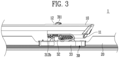
- FIGS. 3 and 4 are side views of the wiper device according to one embodiment of the present disclosure
- FIGS. 5 and 6 are exploded perspective views of the wiper device according to one embodiment of the present disclosure.
- FIG. 7 is a partially exploded perspective view of the wiper device according to one embodiment of the present disclosure
- FIG. 8 is a partially exploded side view of the wiper device according to one embodiment of the present disclosure
- FIG. 9 is a partial perspective view of the wiper device according to one embodiment of the present disclosure.
- FIG. 10 is a partial side cross-sectional view of the wiper device according to one embodiment of the present disclosure
- FIG. 11 is a partial bottom view of the wiper device according to one embodiment of the present disclosure
- FIG. 12 is a partial side cross-sectional view of the wiper device according to one embodiment of the present disclosure
- FIG. 13 is a partial bottom view of the wiper device according to one embodiment of the present disclosure.
- FIG. 14 is a partial perspective view of the wiper device according to one embodiment of the present disclosure.
- FIGS. 1 to 4 are views showing a second state to be described below
- FIGS. 7 to 9 are views showing a zeroth state to be described below
- FIGS. 10 and 11 are views showing a first state to be described below
- FIGS. 12 to 14 are also views showing the second state.
- a longitudinal direction is a direction in which a wiper blade 20 or a wiper arm 10 extends, and may be a left-right direction based on FIG. 3 .
- a width direction may be a direction perpendicular to the longitudinal direction.
- a height direction may be a direction away from a close contact target with which the wiper blade 20 is in close contact and may be a vertical direction based on FIG. 3 .
- the above directions do not limit the scope of the present disclosure, but are merely for convenience in the description of the present disclosure.
- a wiper device 1 includes a wiper arm 10, a wiper blade 20, and a wiper connector 30.
- the wiper arm 10, the wiper blade 20, the wiper connector 30, etc. may be collectively referred to as the wiper device 1, and in the wiper device 1, the components (the wiper blade 20 and the wiper connector 30) other than the wiper arm 10 and the like may be referred to as an assembly of a wiper blade 20.
- the wiper device 1 may be formed in a form in which the wiper arm 10 is connected to the assembly of the wiper blade 20.
- the wiper arm 10 has a base end to be rotatably connected and an end to which the wiper blade 20 is connected.
- the wiper arm 10 is implemented to transmit a rotational force to the wiper blade 20 connected to the end while rotating about the base end so that the wiper blade 20 cleans a close contact target.
- the close contact target may be a windshield of a vehicle, but is not limited thereto, and any object that can be cleaned by sliding may be the close contact target.
- the close contact target is the windshield for convenience.
- the wiper arm 10 is directly or indirectly connected to a driving source (motor or the like) provided in the vehicle or the like and has the end that rotates along an arc by a rotational force of the driving source. At this time, since the wiper blade 20 is connected to the end of the wiper arm 10, the wiper blade 20 may implement cleaning while moving along a predetermined path in a state of being in close contact with the close contact target.
- a driving source motor or the like
- the wiper arm 10 has a washing liquid spray nozzle 11.
- the washing liquid is sprayed through the nozzle disposed to be spaced apart from the wiper arm 10, but in the present disclosure, by integrating the washing liquid spray nozzle 11 into the wiper arm 10, it is possible to efficiently supply the washing liquid to a portion to be swept with the wiper blade 20.
- the washing liquid spray nozzle 11 may be embedded in the wiper arm 10 to face the wiper blade 20 or the close contact target.
- the washing liquid spray nozzle 11 may be connected to a washing liquid supply source (not shown) through a washing liquid supply tube (not shown), and the washing liquid may be sprayed through the washing liquid spray nozzle 11 at a constant pressure by performing a separate operation.
- a pair of washing liquid spray nozzles 11 may be provided and disposed in parallel at both sides at a front end of the wiper arm 10. Therefore, since the washing liquid may be sprayed at start and end points of a sweep direction of the wiper blade 20, it is possible to further increase a washing force for the close contact target.
- the wiper connector 30 to be described below may be inserted into a space between the pair of washing liquid spray nozzles 11 provided on the wiper arm 10.
- the washing liquid spray nozzle 11 is provided not to interfere with the wiper connector 30 when embedded in the wiper arm 10.
- the wiper arm 10 may have various unlimited shapes, and a shape of the wiper connector 30 may be freely changed to correspond to the shape of the wiper arm 10.
- the wiper connector 30 may also be provided in a multi-fastening type in which a plurality of wiper arms 10 having different shapes may be selectively coupled.
- the wiper arm 10 in the embodiment may have a hole 12 provided in an upper surface thereof to be coupled with the wiper connector 30.
- the hole 12 is configured to fasten a first fastener 311 of the wiper connector 30 to be described below and has a larger planar cross-section than the first fastener 311 so that the first fastener 311 may pass therethrough and a form in which a part of the first fastener 311 is movable in the longitudinal direction.
- the first fastener 311 may pass through the hole 12 of the wiper arm 10, and the first fastener 311 may move in the longitudinal direction in the state of passing through the hole 12 of the wiper arm 10.
- the first fastener 311 has a "T-shaped cross section and couples the wiper arm 10 and the wiper connector 30 by moving in the longitudinal direction in the state of passing through a certain portion of the hole 12 of the wiper arm 10 and being caught by the hole 12 of the wiper arm 10.
- the hole 12 of the wiper arm 10 and the first fastener 311 are implemented for fixing in the height direction and the width direction, and fixing in the longitudinal direction is implemented using a second fastener 312 to be described below.
- the wiper arm 10 includes a rib 13 therein for fastening of the second fastener 312.
- the rib 13 is provided inside the wiper arm 10 and has a shape protruding from an inner surface of the wiper arm 10 in the width direction.
- the rib 13 is provided to interfere with the second fastener 312 when the first fastener 311 of the wiper connector 30 is vertically disposed side by side in the hole 12 of the wiper arm 10. This case means that the first fastener 311 may pass through the hole 12.
- the rib 13 is provided not to interfere with the second fastener 312 in the state in which the first fastener 311 of the wiper connector 30 is fastened to the hole 12 of the wiper arm 10. However, this will be described in detail below.
- the rib 13 of the wiper arm 10 is configured to elastically deform the second fastener 312 while pressing a pressing portion 312a provided on the second fastener 312, and an inclined surface or a curved surface may be applied to at least one side of a portion in which the second fastener 312 and the rib 13 are in contact with each other.
- the drawings show that the rib 13 has a planar surface and the pressing portion 312a has an inclined surface, the rib 13 may have an inclined surface and the pressing portion 312a may have a planar surface, or both the rib 13 and the pressing portion 312a may have inclined surfaces.
- the rib 13 may be provided to have a partition wall shape in the width direction inside the wiper arm 10 and may serve to reinforce the structural strength of the wiper arm 10. In this case, since the rib 13 has a shape in which at least a portion is recessed upward, the second fastener 312 may be elastically deformed through the recessed portion of the rib 13.
- the wiper blade 20 is in close contact with a surface of the close contact target and cleans the surface of the close contact target by movement.
- the close contact target may be any object to be cleaned by sliding, such as a windshield of a vehicle.
- the wiper blade 20 may include a close contact member (not shown), an elastic member (not shown), a cover member (not shown), and a finishing cover (not shown).
- the close contact member is in direct close contact with the surface of the close contact target and slides along the surface.
- the close contact member may have a shape in which a close contact side is different from the surface of the close contact target in a state in which an external force is not applied thereto and then may be deformed into a shape in which the close contact side is naturally consistent with the surface of the close contact target while being pressed toward the close contact target when the wiper blade 20 is coupled to the wiper arm 10 through the wiper connector 30.
- the elastic member is made of a metal material and embedded inside the wiper blade 20 to apply an elastic force to the close contact member.
- the elastic member may be provided as a plate spring or the like and give an elastic force, which allows the close contact member to return to a more curved shape than the surface of the close contact target, to the close contact member. Therefore, when the close contact member is pressed to the close contact target by the wiper arm 10, the close contact side of the close contact member is deformed and applies a force to push the close contact target, but the close contact side may be firmly in close contact with the close contact target while maintaining the state of being pressed by the wiper arm 10.
- the cover member is provided at a side opposite to the close contact member and has an A-shaped or mountain-shaped cross-section at the top, thereby preventing the wiper blade 20 from being lifted by wind while a vehicle travels.
- the finishing cover (not shown) may be provided to finish both ends of the cover member and the close contact member and isolate the elastic member from the outside.
- a pair of finishing covers may be provided at both ends of the wiper blade 20 in the longitudinal direction, but the finishing covers may be omitted depending on the shape of the cover member.
- the wiper arm 10 may be connected to a central portion of the wiper blade 20 in the longitudinal direction.
- the wiper connector 30 is seated on the central portion of the wiper blade 20 in the longitudinal direction.
- a base portion 33 of the wiper connector 30 to be described below may be coupled to the wiper blade 20, and in a coupling method between the wiper connector 30 and the wiper blade 20, protrusion engagement, rivet, bolting, etc. may be used.
- a pair of cover members or the like may have a shape in which the pair of cover members are spaced apart from each other with respect to the center of the wiper blade 20.
- the wiper connector 30 is for mutually fastening the wiper blade 20 and the wiper arm 10 and may be referred to as an adapter.
- the wiper connector 30 does not only have a shape completely separable from the wiper blade 20, the wiper arm 10, etc. and may be formed by a part of the wiper blade 20, or may also be formed in a shape in which at least a portion is integrated into the wiper blade 20 or the wiper arm 10.
- the wiper connector 30 will be described as a separate component provided independently of the wiper blade 20 and the wiper arm 10.
- the wiper connector 30 includes an insertion portion 31, a fixing portion 32, and the base portion 33.
- the insertion portion 31 is inserted into the wiper arm 10 and disposed at one side of the washing liquid spray nozzle 11 provided on the wiper arm 10. As described above, the pair of washing liquid spray nozzles 11 may be provided on the wiper arm 10, and the insertion portion 31 may be disposed between the pair of washing liquid spray nozzles 11.
- At least a part of the insertion portion 31 is inserted into the wiper arm 10 and fixed to the wiper arm 10, and a part of a lower portion of the insertion portion 31 may be exposed to the outside of the wiper arm 10.
- a part of the second fastener 312 provided on the insertion portion 31 is exposed to the outside.
- the insertion portion 31 has the first fastener 311 and the second fastener 312 to be fixed to the wiper arm 10.
- the first fastener 311 restricts movement between the wiper connector 30 and the wiper arm 10 in the height direction and the width direction.
- the first fastener 311 is caught by the hole 12 provided in an upper surface of the wiper arm 10.
- the hole 12 having a size that the first fastener 311 can pass through may be provided in the upper surface of the wiper arm 10, and the first fastener 311 may be switched to enter a second state of being caught by the hole 12 from a first state of passing through the hole 12.
- the first fastener 311 is provided to have a lower end 311b and an upper end 311a and has a hook shape (e.g., a " ⁇ " shape) in which the upper end 311a has a relatively larger area than the lower end 311b.
- the area of the upper end 311a of the first fastener 311 is smaller than the area of the hole 12 so that the first fastener 311 passes through the hole 12 of the wiper arm 10.
- the first fastener 311 is switched between the first state in which the upper end 311a passes through the hole 12 and the second state in which the lower end 311b moves in the hole 12 so that at least a part of the upper end 311a is misaligned with the hole 12.
- the first state since the upper end 311a of the first fastener 311 is disposed to pass through the hole 12 in the height direction, the movement of the first fastener 311 in the width direction with respect to the wiper arm 10 is restricted, but the movement thereof in the height direction may not be restricted.
- the first fastener 311 when the first fastener 311 is in the second state, a part of the upper end 311a of the first fastener 311 is misaligned with the hole 12 to face the close upper surface of the wiper arm 10, and thus the first fastener 311 may not move downward from the hole 12.
- the first fastener 311 since the upper surface of the insertion portion 31 faces the surrounding of the hole 12, the first fastener 311 may not move upward from the hole 12. Therefore, the first fastener 311 restricts the movement of the wiper arm 10 in the width direction and the longitudinal direction in the second state.
- the state of FIGS. 7 to 9 in which the first fastener 311 is disposed just under the hole 12 and which is a state before the first fastener 311 passes through the hole 12 may be defined as a zeroth state.
- the second fastener 312 is caught by the rib 13 provided inside the wiper arm 10.
- the second fastener 312 is provided in an elastically deformable form and is in the first state of being elastically deformed by being pressed by the rib 13 when the first fastener 311 passes through the hole 12.
- the second fastener 312 passes the rib 13 and is restored to an original state by the elastic force, and at this time, the second fastener 312 enters the second state of restricting the movement of the wiper arm 10 in the longitudinal direction.
- the second fastener 312 may limit the retract of the wiper arm 10 in the longitudinal direction with respect to the wiper connector 30 while facing the rib 13 at a rear side thereof, and the advance of the wiper arm 10 in the longitudinal direction with respect to the wiper connector 30 may be limited by the insertion portion 31 itself and an inner structure of the wiper arm 10 in contact with each other.
- one or more ribs 13 may be provided on the wiper arm 10, and the rib 13 is additionally disposed in front of the second fastener 312 in the second state in the longitudinal direction so that the front-rear movement of the wiper arm 10 in the longitudinal direction may be all restricted by only the second fastener 312.
- the insertion portion 31 has a shape that does not interfere with the rib 13 when moving upward to the wiper arm 10 to pass the first fastener 311 through the hole 12.
- the second fastener 312 has a cantilever shape and includes the pressing portion 312a, a button portion 312b, etc.
- the pressing portion 312a is disposed above the second fastener 312 having the cantilever shape adjacent to the wiper arm 10 and induces the deformation of the wiper arm 10 inward in the width direction with respect to the second fastener 312 while being pressed by the rib 13 of the wiper arm 10 when the wiper connector 30 and the wiper arm 10 are fastened to each other.
- one surface of the pressing portion 312a facing the rib 13 may have an inclined surface or curved surface shape.
- the pressing portion 312a is in contact with or faces the rib 13 in the second state to limit the movement of the wiper arm 10 in the longitudinal direction, and a thickness of the pressing portion 312a in the width direction may be sufficiently determined in consideration of the fastening force of the wiper arm 10.
- the button portion 312b is disposed at a lower portion of the second fastener 312 having the cantilever shape that is far from the wiper arm 10 and moves integrally with the pressing portion 312a.
- the button portion 312b may have at least a part exposed to the outside and may be pressed by a user.
- the button portion 312b may be sufficiently exposed to be easily pressed by the user, and an uneven structure may also be applied to the surface to enhance the user's pressing convenience.
- a recess structure may be applied to an exposed surface of the button portion 312b, and unevenness may be given thereto.
- friction protrusion may also be added.
- the button portion 312b may have an area that may be sufficiently pressed by at least one fingertip, but has a form in a range in which the hinge movement of the fixing portion 32 and the base portion 33 is not interfered with the button portion 312b.
- the button portion 312b may have an outstanding color when compared to the wiper arm 10 or the insertion portion 31, and thus when the user separates the wiper arm 10 from the wiper connector 30, the user can easily find the button portion 312b.
- the button portion 312b is deformed inward in the width direction of the wiper arm 10 by an external force.
- the direction in which the pressing portion 312a is deformed by being pressed by the rib 13 and the direction in which the button portion 312b is deformed by being pressed by the external force are the same.
- the wiper connector 30 is disposed to be movable backward from the wiper arm 10.
- a state in which in the second state, the pressing portion 312a is misaligned with the rib 13 as the button portion 312b is pressed, and thus the second fastener 312 is movably disposed in the longitudinal direction with respect to the wiper arm is defined as the third state.
- the button portion 312b is pressed by the external force, the switching from the second state to the third state may be made.
- the fixing portion 32 is integrally provided with the insertion portion 31 and fixed to the wiper blade 20.
- the fixing portion 32 may be provided under the insertion portion 31 and manufactured separately and then connected to the insertion portion 31 or integrally manufactured with the insertion portion 31.
- the fixing portion 32 may be integrated with the insertion portion 31 in a shape in which a point structurally separated from the insertion portion 31 is not clearly partitioned, but a portion under the second fastener 312 having the cantilever shape may be defined as the fixing portion 32.
- the fixing portion 32 may be directly or indirectly connected to the wiper blade 20, and in the embodiment, the fixing portion 32 may be indirectly connected to the wiper blade 20 through the base portion 33 fastened to the wiper blade 20.
- the fixing portion 32 may be provided to be hinge-rotated with respect to the wiper blade 20, and to this end, a rotational shaft 321 is provided on the fixing portion 32.
- the rotational shaft 321 may have a bar shape extending from the fixing portion 32 in the width direction or have at least a pair of protrusion shapes capable of implementing a stable hinge rotation on the base portion 33.
- the fixing portion 32 may be rotatably provided with the wiper blade 20 in the longitudinal direction using the rotational shaft 321, and therefore, even when an angle between the wiper arm 10 and the close contact target is changed, the wiper blade 20 can be in stable close contact with the close contact target.
- the base portion 33 is provided on the wiper blade 20.
- the base portion 33 may be provided at the central point of the wiper blade 20 in the longitudinal direction and fastened to the close contact member, the cover member, etc. of the wiper blade 20.
- a pair of cover members of the wiper blade 20 may be divided with respect to the central portion of the wiper blade 20 in the longitudinal direction, and the base portion 33 may be fixedly seated in a space between the pair of cover members.
- a rotation groove 331 is provided in the base portion 33.
- the rotation groove 331 of the base portion 33 accommodates the rotational shaft 321 provided on the fixing portion 32, but has a shape in which the rotational shaft 321 is not easily separated.
- an open top of the rotation groove 331 may be formed in a shape having a smaller diameter than a diameter of the rotational shaft 321 of the base portion 33.
- the rotational shaft 321 and the rotation groove 331 may also be disposed in an opposite way. That is, the rotation groove 331 may be provided in the fixing portion 32, and the rotational shaft 321 may also be provided on the base portion 33.
- the wiper connector 30 may also be fastened to the wiper blade 20 without hinge rotation, and in this case, the base portion 33 may be omitted, and the fixing portion 32 may also be directly coupled to the wiper blade 20.
- the fixing portion 32 may have a structure that is detachably coupled to the wiper blade 20 or the fixing portion 32 may be integrated with the wiper blade 20, and thus the wiper blade 20 and the wiper connector 30 may be integrally provided.
- the base portion 33 may be separated from the wiper blade 20, and the base portion 33 and the wiper blade 20 may be assembled in a manufacturing process rather than user work. In other words, the base portion 33 may be integrated with the wiper blade 20 at the time of manufacture.
- FIGS. 7 and 8 show the wiper connector 30 in which the base portion 33 is omitted, but the starting step in which the user couples the wiper connector 30 to the wiper arm 10 will be described assuming as being a state in which the base portion 33 is already fastened on the wiper blade 20, and the base portion 33 and the fixing portion 32 are interconnected so that the wiper connector 30 is connected to the wiper blade 20.
- the wiper connector 30 is disposed under the wiper arm 10 in the height direction.
- the upper end 311a of the first fastener 311 is provided just under the hole 12 provided in the upper surface of the wiper arm 10.
- such a state may be defined as the zeroth state.
- the zeroth state is a state in which the wiper arm 10 and the wiper connector 30 are vertically disposed in a column and the fastening to the first fastener 311 is prepared.
- the wiper connector 30 is disposed adjacent to the wiper arm 10 when compared to FIGS. 7 and 8 .
- This state is that the wiper connector 30 moves toward the wiper arm 10 when compared to FIG. 7 and the like, but may still be defined as the zeroth state.
- the pressing portion 312a of the second fastener 312 is in contact with the rib 13.
- states from the state of the wiper arm 10 separated from the wiper connector 30 to the state of the second fastener 312 in contact with the rib 13 of the wiper arm 10 are collectively referred to as the zeroth state.
- the rib 13 is in contact with the pressing portion 312a of the second fastener 312 with an inclined surface, and in this case, when a predetermined external force (an extent to which the rib 13 deforms the pressing portion 312a) is not applied, the wiper connector 30 is not inserted into the wiper arm 10.
- the wiper connector 30 may be completely inserted into the wiper arm 10, and the first fastener 311 may pass through the hole 12 provided in the wiper arm 10.
- the upper end 311a of the first fastener 311 may pass through the hole 12, and the lower end 311b of the first fastener 311 is positioned in the hole 12.
- the pressing portion 312a of the second fastener 312 is pressed by the rib 13.
- the rib 13 presses the inclined surface of the pressing portion 312a and thus the second fastener 312 is elastically deformed.
- a free end of the second fastener 312 having the cantilever shape is bent inward from the wiper arm 10 in the width direction, and in this case, the pressing portion 312a is misaligned inward from the rib 13 in the width direction.
- the above state is defined as the first state, and in the first state, the first fastener 311 is in a state of passing through the hole 12, but does not restrict the movement of the wiper arm 10 in the height direction and the longitudinal direction.
- the first fastener 311 may restrict the movement of the wiper arm 10 in the height direction and the width direction.
- the first fastener 311 may be not seen as completely restricting the movement of the wiper arm 10 in the longitudinal direction.
- the second fastener 312 restricts the movement of the wiper arm 10 in the longitudinal direction. Specifically, the second fastener 312 is restored to the original state by the elastic force as the pressing portion 312a passes the rib 13 forward in the longitudinal direction. In this case, since the pressing portion 312a of the second fastener 312 is disposed to overlap the rib 13 in the longitudinal direction, and as can be seen in FIG. 14 , the backward movement of the pressing portion 312a in the longitudinal direction is limited by the rib 13.
- the second state is a state in which the wiper arm 10 is completely fastened to the wiper blade 20 by the wiper connector 30. Specifically, the movement of the wiper arm 10 in the height direction and the width direction is restricted by the first fastener 311, and the movement of the wiper arm 10 in the longitudinal direction (backward movement) is restricted by the second fastener 312, and the movement of the wiper arm 10 in the longitudinal direction (advance) is restricted by the insertion portion 31.
- the movement of the wiper arm 10 in the width direction may be additionally restricted by the insertion portion 31 inserted into the wiper arm 10.
- one or more protrusions (not shown), which allows the insertion portion 31 to face or be in contact with the inner surface of the wiper arm 10, may be provided on both side surfaces of the insertion portion 31.
- the first fastener 311 may pass through the hole 12 of the wiper arm 10, and in the state of being inserted into the hole 12, the movement of the first fastener 311 in the width direction may be naturally restricted by the hole 12, and thus the first fastener 311 may structurally restrict the movement of the wiper arm 10 in the width direction.
- one or more protrusions in the longitudinal direction and/or one or more protrusions in the height direction may be disposed to protrude from a side surface of the insertion portion 31.
- the protruding degree of the protrusion may be uniformly or non-uniformly determined depending on the shape of the inner surface of the wiper arm 10.
- At least some of the plurality of protrusions may be in direct contact with the inner structure of the wiper arm 10, thereby not only sufficiently limiting the movement of the wiper arm 10 in the width direction but also effectively suppressing shaking.
- the user may press the button portion 312b of the second fastener 312.
- the pressing portion 312a also moves inward in the width direction of the wiper arm 10, and thus the pressing portion 312a is misaligned with the rib 13 in the longitudinal direction. Therefore, the wiper connector 30 can move backward in the longitudinal direction with respect to the wiper arm 10.
- a state in which the pressing portion 312a is misaligned with the rib 13 when the button portion 312b of the second fastener 312 is pressed may be defined as the third state.
- the user may retract the wiper connector 30 in the longitudinal direction with respect to the wiper arm 10, and when the wiper connector 30 sufficiently moves backward, this returns to the first state in which the first fastener 311 may pass through the hole 12 of the wiper arm 10.
- the user may move the wiper connector 30 downward from the wiper arm 10, and thus the wiper arm 10 and the wiper blade 20 are separated.
- the wiper connector 30 partially inserted into the wiper arm 10 is provided, and it is possible to not only simply couple the wiper arm 10 and the wiper connector 30, but also easily separate the wiper arm 10 from the wiper connector 30 through the button operation, thereby maximizing the user's convenience.
- a wiper connector, a wiper blade assembly, and a wiper device it is possible to apply an adapter that is easily fastened to and separated from a wiper arm having a washing liquid spray nozzle by performing a simple operation, thereby securing fixing strength between the wiper arm and the adapter and easily disassembling the wiper arm from the adapter.
- the present disclosure relates to a wiper connector, a wiper blade assembly, and a wiper device, and a wiper connector for mutually connecting a wiper blade and a wiper arm includes an insertion portion inserted into the wiper arm and disposed at one side of a washing liquid spray nozzle provided on the wiper arm, and a fixing portion integrally provided with the insertion portion and fixed to the wiper blade, wherein the insertion portion includes a first fastener caught by a hole provided in an upper surface of the wiper arm, and a second fastener caught by a rib provided inside the wiper arm.
Landscapes
- Engineering & Computer Science (AREA)
- Mechanical Engineering (AREA)
- Water Supply & Treatment (AREA)
- Cleaning Implements For Floors, Carpets, Furniture, Walls, And The Like (AREA)
Applications Claiming Priority (1)
| Application Number | Priority Date | Filing Date | Title |
|---|---|---|---|
| KR1020220035003A KR102673613B1 (ko) | 2022-03-21 | 2022-03-21 | 와이퍼용 체결기구, 와이퍼 블레이드 조립체 및 와이퍼 장치 |
Publications (2)
| Publication Number | Publication Date |
|---|---|
| EP4249330A1 true EP4249330A1 (fr) | 2023-09-27 |
| EP4249330B1 EP4249330B1 (fr) | 2025-07-30 |
Family
ID=85703889
Family Applications (1)
| Application Number | Title | Priority Date | Filing Date |
|---|---|---|---|
| EP23162086.5A Active EP4249330B1 (fr) | 2022-03-21 | 2023-03-15 | Connecteur d'essuie-glace, ensemble balai d'essuie-glace et dispositif d'essuie-glace |
Country Status (3)
| Country | Link |
|---|---|
| US (1) | US12065107B2 (fr) |
| EP (1) | EP4249330B1 (fr) |
| KR (1) | KR102673613B1 (fr) |
Citations (2)
| Publication number | Priority date | Publication date | Assignee | Title |
|---|---|---|---|---|
| US20170066418A1 (en) * | 2015-09-07 | 2017-03-09 | Valeo Systèmes d'Essuyage | Wiper device for cleaning vehicle windows, and cleaning arrangement for a wiper device |
| DE112015003232T5 (de) * | 2014-07-11 | 2017-05-18 | Valeo Systèmes d'Éssuyage | Adapter zum Verbinden eines Scheibenwischerblatts mit einem Antriebsarm dieses Blatts |
Family Cites Families (6)
| Publication number | Priority date | Publication date | Assignee | Title |
|---|---|---|---|---|
| FR2781741B1 (fr) * | 1998-07-31 | 2000-09-22 | Valeo Systemes Dessuyage | Essuie-glace comprenant au moins un premier et un second element relies par l'intermediaire d'une piece de liaison |
| DE102005016486A1 (de) * | 2005-04-08 | 2006-10-12 | Robert Bosch Gmbh | Vorrichtung zum gelenkigen Verbinden eines Wischblatts mit einem Wischarm eines Scheibenwischers |
| PL2460700T3 (pl) | 2010-12-02 | 2014-05-30 | Valeo Systemes Dessuyage | Hydrauliczny łącznik dla pióra wycieraczki przedniej szyby |
| FR2981622B1 (fr) * | 2011-10-25 | 2014-09-12 | Valeo Systemes Dessuyage | Dispositif de fixation d'essuie-glace a position de securite, connecteur et adaptateur d'un tel dispositif et systeme d'essuyage comprenant ledit dispositif de fixation. |
| KR101681224B1 (ko) * | 2014-04-18 | 2016-12-01 | 서덕희 | 다중 결합구조의 자동차용 와이퍼 |
| FR3066457B1 (fr) * | 2017-05-19 | 2019-07-12 | Valeo Systemes D'essuyage | Adaptateur destine a relier un balai d'essuyage a un bras d'entrainement d'un systeme d'essuyage |
-
2022
- 2022-03-21 KR KR1020220035003A patent/KR102673613B1/ko active Active
-
2023
- 2023-03-15 EP EP23162086.5A patent/EP4249330B1/fr active Active
- 2023-03-20 US US18/186,510 patent/US12065107B2/en active Active
Patent Citations (2)
| Publication number | Priority date | Publication date | Assignee | Title |
|---|---|---|---|---|
| DE112015003232T5 (de) * | 2014-07-11 | 2017-05-18 | Valeo Systèmes d'Éssuyage | Adapter zum Verbinden eines Scheibenwischerblatts mit einem Antriebsarm dieses Blatts |
| US20170066418A1 (en) * | 2015-09-07 | 2017-03-09 | Valeo Systèmes d'Essuyage | Wiper device for cleaning vehicle windows, and cleaning arrangement for a wiper device |
Also Published As
| Publication number | Publication date |
|---|---|
| US20230294642A1 (en) | 2023-09-21 |
| US12065107B2 (en) | 2024-08-20 |
| EP4249330B1 (fr) | 2025-07-30 |
| KR20230137178A (ko) | 2023-10-04 |
| KR102673613B1 (ko) | 2024-06-12 |
Similar Documents
| Publication | Publication Date | Title |
|---|---|---|
| EP1584527B1 (fr) | Dispositif d'essuyage | |
| JP4580124B2 (ja) | ワイパアーム | |
| US20140041143A1 (en) | Wiper blade assembly | |
| JP3781904B2 (ja) | トリガー式液体噴出器における合成樹脂製復帰ばね | |
| CN107531215A (zh) | 雨刮器装置 | |
| EP4249330A1 (fr) | Connecteur d'essuie-glace, ensemble balai d'essuie-glace et dispositif d'essuie-glace | |
| CN217827679U (zh) | 一种窗擦 | |
| EP3808614B1 (fr) | Adaptateur d'assemblage de balai d'essuie-glace, ensemble balai d'essuie-glace et appareil d'essuie-glace | |
| JP6441156B2 (ja) | ワイパ装置 | |
| CN217447634U (zh) | 振动机构、清洁组件及清洁设备 | |
| JP6437235B2 (ja) | ワイパ装置 | |
| CN113116241B (zh) | 清洁组件、清洁装置及控制方法 | |
| CN217365675U (zh) | 清洁刷组件及表面清洁装置 | |
| CN110001590B (zh) | 刮片和刮水器 | |
| JP2619828B2 (ja) | 電動式爪みがき機 | |
| JP5307668B2 (ja) | 電気掃除機 | |
| CN223126431U (zh) | 清洁组件和清洁设备 | |
| KR102310968B1 (ko) | 와이퍼 암 선단부에 설치되는 워셔액 분사 노즐 장치 | |
| CN218500611U (zh) | 一种角度自适应的窗擦 | |
| CN113815570B (zh) | 一种连接器及雨刷 | |
| CN218684153U (zh) | 一种滚刷侧向拆卸的清洁装置 | |
| CN116369787B (zh) | 一种扫地机器人基站及扫地机器人系统 | |
| CN219578832U (zh) | 一种便于更换擦拭物的平板拖把 | |
| JPH0341603Y2 (fr) | ||
| CN114190829B (zh) | 清洁机器人的清洁组件和具有其的清洁机器人 |
Legal Events
| Date | Code | Title | Description |
|---|---|---|---|
| PUAI | Public reference made under article 153(3) epc to a published international application that has entered the european phase |
Free format text: ORIGINAL CODE: 0009012 |
|
| STAA | Information on the status of an ep patent application or granted ep patent |
Free format text: STATUS: REQUEST FOR EXAMINATION WAS MADE |
|
| 17P | Request for examination filed |
Effective date: 20230315 |
|
| AK | Designated contracting states |
Kind code of ref document: A1 Designated state(s): AL AT BE BG CH CY CZ DE DK EE ES FI FR GB GR HR HU IE IS IT LI LT LU LV MC ME MK MT NL NO PL PT RO RS SE SI SK SM TR |
|
| GRAP | Despatch of communication of intention to grant a patent |
Free format text: ORIGINAL CODE: EPIDOSNIGR1 |
|
| STAA | Information on the status of an ep patent application or granted ep patent |
Free format text: STATUS: GRANT OF PATENT IS INTENDED |
|
| INTG | Intention to grant announced |
Effective date: 20250324 |
|
| GRAS | Grant fee paid |
Free format text: ORIGINAL CODE: EPIDOSNIGR3 |
|
| GRAA | (expected) grant |
Free format text: ORIGINAL CODE: 0009210 |
|
| STAA | Information on the status of an ep patent application or granted ep patent |
Free format text: STATUS: THE PATENT HAS BEEN GRANTED |
|
| AK | Designated contracting states |
Kind code of ref document: B1 Designated state(s): AL AT BE BG CH CY CZ DE DK EE ES FI FR GB GR HR HU IE IS IT LI LT LU LV MC ME MK MT NL NO PL PT RO RS SE SI SK SM TR |
|
| REG | Reference to a national code |
Ref country code: GB Ref legal event code: FG4D |
|
| REG | Reference to a national code |
Ref country code: CH Ref legal event code: EP |
|
| REG | Reference to a national code |
Ref country code: DE Ref legal event code: R096 Ref document number: 602023005110 Country of ref document: DE |
|
| REG | Reference to a national code |
Ref country code: IE Ref legal event code: FG4D |
|
| REG | Reference to a national code |
Ref country code: NL Ref legal event code: MP Effective date: 20250730 |
|
| REG | Reference to a national code |
Ref country code: AT Ref legal event code: MK05 Ref document number: 1818626 Country of ref document: AT Kind code of ref document: T Effective date: 20250730 |
|
| PG25 | Lapsed in a contracting state [announced via postgrant information from national office to epo] |
Ref country code: PT Free format text: LAPSE BECAUSE OF FAILURE TO SUBMIT A TRANSLATION OF THE DESCRIPTION OR TO PAY THE FEE WITHIN THE PRESCRIBED TIME-LIMIT Effective date: 20251202 |
|
| PG25 | Lapsed in a contracting state [announced via postgrant information from national office to epo] |
Ref country code: IS Free format text: LAPSE BECAUSE OF FAILURE TO SUBMIT A TRANSLATION OF THE DESCRIPTION OR TO PAY THE FEE WITHIN THE PRESCRIBED TIME-LIMIT Effective date: 20251130 |
|
| PG25 | Lapsed in a contracting state [announced via postgrant information from national office to epo] |
Ref country code: NO Free format text: LAPSE BECAUSE OF FAILURE TO SUBMIT A TRANSLATION OF THE DESCRIPTION OR TO PAY THE FEE WITHIN THE PRESCRIBED TIME-LIMIT Effective date: 20251030 |
|
| REG | Reference to a national code |
Ref country code: LT Ref legal event code: MG9D |
|
| PG25 | Lapsed in a contracting state [announced via postgrant information from national office to epo] |
Ref country code: AT Free format text: LAPSE BECAUSE OF FAILURE TO SUBMIT A TRANSLATION OF THE DESCRIPTION OR TO PAY THE FEE WITHIN THE PRESCRIBED TIME-LIMIT Effective date: 20250730 |
|
| PG25 | Lapsed in a contracting state [announced via postgrant information from national office to epo] |
Ref country code: FI Free format text: LAPSE BECAUSE OF FAILURE TO SUBMIT A TRANSLATION OF THE DESCRIPTION OR TO PAY THE FEE WITHIN THE PRESCRIBED TIME-LIMIT Effective date: 20250730 |
|
| PG25 | Lapsed in a contracting state [announced via postgrant information from national office to epo] |
Ref country code: HR Free format text: LAPSE BECAUSE OF FAILURE TO SUBMIT A TRANSLATION OF THE DESCRIPTION OR TO PAY THE FEE WITHIN THE PRESCRIBED TIME-LIMIT Effective date: 20250730 Ref country code: NL Free format text: LAPSE BECAUSE OF FAILURE TO SUBMIT A TRANSLATION OF THE DESCRIPTION OR TO PAY THE FEE WITHIN THE PRESCRIBED TIME-LIMIT Effective date: 20250730 |
|
| PG25 | Lapsed in a contracting state [announced via postgrant information from national office to epo] |
Ref country code: GR Free format text: LAPSE BECAUSE OF FAILURE TO SUBMIT A TRANSLATION OF THE DESCRIPTION OR TO PAY THE FEE WITHIN THE PRESCRIBED TIME-LIMIT Effective date: 20251031 |
|
| PG25 | Lapsed in a contracting state [announced via postgrant information from national office to epo] |
Ref country code: SE Free format text: LAPSE BECAUSE OF FAILURE TO SUBMIT A TRANSLATION OF THE DESCRIPTION OR TO PAY THE FEE WITHIN THE PRESCRIBED TIME-LIMIT Effective date: 20250730 |
|
| PG25 | Lapsed in a contracting state [announced via postgrant information from national office to epo] |
Ref country code: LV Free format text: LAPSE BECAUSE OF FAILURE TO SUBMIT A TRANSLATION OF THE DESCRIPTION OR TO PAY THE FEE WITHIN THE PRESCRIBED TIME-LIMIT Effective date: 20250730 |
|
| PG25 | Lapsed in a contracting state [announced via postgrant information from national office to epo] |
Ref country code: PL Free format text: LAPSE BECAUSE OF FAILURE TO SUBMIT A TRANSLATION OF THE DESCRIPTION OR TO PAY THE FEE WITHIN THE PRESCRIBED TIME-LIMIT Effective date: 20250730 Ref country code: BG Free format text: LAPSE BECAUSE OF FAILURE TO SUBMIT A TRANSLATION OF THE DESCRIPTION OR TO PAY THE FEE WITHIN THE PRESCRIBED TIME-LIMIT Effective date: 20250730 |
|
| PG25 | Lapsed in a contracting state [announced via postgrant information from national office to epo] |
Ref country code: RS Free format text: LAPSE BECAUSE OF FAILURE TO SUBMIT A TRANSLATION OF THE DESCRIPTION OR TO PAY THE FEE WITHIN THE PRESCRIBED TIME-LIMIT Effective date: 20251030 |
|
| PG25 | Lapsed in a contracting state [announced via postgrant information from national office to epo] |
Ref country code: ES Free format text: LAPSE BECAUSE OF FAILURE TO SUBMIT A TRANSLATION OF THE DESCRIPTION OR TO PAY THE FEE WITHIN THE PRESCRIBED TIME-LIMIT Effective date: 20250730 |
|
| PG25 | Lapsed in a contracting state [announced via postgrant information from national office to epo] |
Ref country code: SM Free format text: LAPSE BECAUSE OF FAILURE TO SUBMIT A TRANSLATION OF THE DESCRIPTION OR TO PAY THE FEE WITHIN THE PRESCRIBED TIME-LIMIT Effective date: 20250730 |
|
| PG25 | Lapsed in a contracting state [announced via postgrant information from national office to epo] |
Ref country code: DK Free format text: LAPSE BECAUSE OF FAILURE TO SUBMIT A TRANSLATION OF THE DESCRIPTION OR TO PAY THE FEE WITHIN THE PRESCRIBED TIME-LIMIT Effective date: 20250730 |
|
| PG25 | Lapsed in a contracting state [announced via postgrant information from national office to epo] |
Ref country code: IT Free format text: LAPSE BECAUSE OF FAILURE TO SUBMIT A TRANSLATION OF THE DESCRIPTION OR TO PAY THE FEE WITHIN THE PRESCRIBED TIME-LIMIT Effective date: 20250730 |
|
| PGFP | Annual fee paid to national office [announced via postgrant information from national office to epo] |
Ref country code: FR Payment date: 20260324 Year of fee payment: 4 |