EP4249405A1 - Transportfahrzeugsystem - Google Patents
Transportfahrzeugsystem Download PDFInfo
- Publication number
- EP4249405A1 EP4249405A1 EP21894323.1A EP21894323A EP4249405A1 EP 4249405 A1 EP4249405 A1 EP 4249405A1 EP 21894323 A EP21894323 A EP 21894323A EP 4249405 A1 EP4249405 A1 EP 4249405A1
- Authority
- EP
- European Patent Office
- Prior art keywords
- transport vehicle
- unit
- measured
- lifting
- overhead transport
- Prior art date
- Legal status (The legal status is an assumption and is not a legal conclusion. Google has not performed a legal analysis and makes no representation as to the accuracy of the status listed.)
- Granted
Links
Images





Classifications
-
- B—PERFORMING OPERATIONS; TRANSPORTING
- B65—CONVEYING; PACKING; STORING; HANDLING THIN OR FILAMENTARY MATERIAL
- B65G—TRANSPORT OR STORAGE DEVICES, e.g. CONVEYORS FOR LOADING OR TIPPING, SHOP CONVEYOR SYSTEMS OR PNEUMATIC TUBE CONVEYORS
- B65G1/00—Storing articles, individually or in orderly arrangement, in warehouses or magazines
- B65G1/02—Storage devices
- B65G1/04—Storage devices mechanical
-
- H—ELECTRICITY
- H10—SEMICONDUCTOR DEVICES; ELECTRIC SOLID-STATE DEVICES NOT OTHERWISE PROVIDED FOR
- H10P—GENERIC PROCESSES OR APPARATUS FOR THE MANUFACTURE OR TREATMENT OF DEVICES COVERED BY CLASS H10
- H10P72/00—Handling or holding of wafers, substrates or devices during manufacture or treatment thereof
- H10P72/30—Handling or holding of wafers, substrates or devices during manufacture or treatment thereof for conveying, e.g. between different workstations
- H10P72/32—Handling or holding of wafers, substrates or devices during manufacture or treatment thereof for conveying, e.g. between different workstations between different workstations
- H10P72/3218—Conveying cassettes, containers or carriers
-
- B—PERFORMING OPERATIONS; TRANSPORTING
- B65—CONVEYING; PACKING; STORING; HANDLING THIN OR FILAMENTARY MATERIAL
- B65G—TRANSPORT OR STORAGE DEVICES, e.g. CONVEYORS FOR LOADING OR TIPPING, SHOP CONVEYOR SYSTEMS OR PNEUMATIC TUBE CONVEYORS
- B65G1/00—Storing articles, individually or in orderly arrangement, in warehouses or magazines
- B65G1/02—Storage devices
- B65G1/04—Storage devices mechanical
- B65G1/0457—Storage devices mechanical with suspended load carriers
-
- B—PERFORMING OPERATIONS; TRANSPORTING
- B65—CONVEYING; PACKING; STORING; HANDLING THIN OR FILAMENTARY MATERIAL
- B65G—TRANSPORT OR STORAGE DEVICES, e.g. CONVEYORS FOR LOADING OR TIPPING, SHOP CONVEYOR SYSTEMS OR PNEUMATIC TUBE CONVEYORS
- B65G43/00—Control devices, e.g. for safety, warning or fault-correcting
-
- H—ELECTRICITY
- H10—SEMICONDUCTOR DEVICES; ELECTRIC SOLID-STATE DEVICES NOT OTHERWISE PROVIDED FOR
- H10P—GENERIC PROCESSES OR APPARATUS FOR THE MANUFACTURE OR TREATMENT OF DEVICES COVERED BY CLASS H10
- H10P72/00—Handling or holding of wafers, substrates or devices during manufacture or treatment thereof
- H10P72/06—Apparatus for monitoring, sorting, marking, testing or measuring
- H10P72/0606—Position monitoring, e.g. misposition detection or presence detection
-
- H—ELECTRICITY
- H10—SEMICONDUCTOR DEVICES; ELECTRIC SOLID-STATE DEVICES NOT OTHERWISE PROVIDED FOR
- H10P—GENERIC PROCESSES OR APPARATUS FOR THE MANUFACTURE OR TREATMENT OF DEVICES COVERED BY CLASS H10
- H10P72/00—Handling or holding of wafers, substrates or devices during manufacture or treatment thereof
- H10P72/30—Handling or holding of wafers, substrates or devices during manufacture or treatment thereof for conveying, e.g. between different workstations
- H10P72/32—Handling or holding of wafers, substrates or devices during manufacture or treatment thereof for conveying, e.g. between different workstations between different workstations
- H10P72/3221—Overhead conveying
-
- H—ELECTRICITY
- H10—SEMICONDUCTOR DEVICES; ELECTRIC SOLID-STATE DEVICES NOT OTHERWISE PROVIDED FOR
- H10P—GENERIC PROCESSES OR APPARATUS FOR THE MANUFACTURE OR TREATMENT OF DEVICES COVERED BY CLASS H10
- H10P72/00—Handling or holding of wafers, substrates or devices during manufacture or treatment thereof
- H10P72/30—Handling or holding of wafers, substrates or devices during manufacture or treatment thereof for conveying, e.g. between different workstations
- H10P72/32—Handling or holding of wafers, substrates or devices during manufacture or treatment thereof for conveying, e.g. between different workstations between different workstations
- H10P72/3222—Loading to or unloading from a conveyor
-
- H—ELECTRICITY
- H10—SEMICONDUCTOR DEVICES; ELECTRIC SOLID-STATE DEVICES NOT OTHERWISE PROVIDED FOR
- H10P—GENERIC PROCESSES OR APPARATUS FOR THE MANUFACTURE OR TREATMENT OF DEVICES COVERED BY CLASS H10
- H10P72/00—Handling or holding of wafers, substrates or devices during manufacture or treatment thereof
- H10P72/50—Handling or holding of wafers, substrates or devices during manufacture or treatment thereof for positioning, orientation or alignment
- H10P72/53—Handling or holding of wafers, substrates or devices during manufacture or treatment thereof for positioning, orientation or alignment using optical controlling means
-
- B—PERFORMING OPERATIONS; TRANSPORTING
- B65—CONVEYING; PACKING; STORING; HANDLING THIN OR FILAMENTARY MATERIAL
- B65G—TRANSPORT OR STORAGE DEVICES, e.g. CONVEYORS FOR LOADING OR TIPPING, SHOP CONVEYOR SYSTEMS OR PNEUMATIC TUBE CONVEYORS
- B65G2203/00—Indexing code relating to control or detection of the articles or the load carriers during conveying
- B65G2203/02—Control or detection
- B65G2203/0208—Control or detection relating to the transported articles
- B65G2203/0233—Position of the article
Definitions
- One aspect of the present invention relates to a transport vehicle system.
- an overhead transport vehicle in which a traveling part configured to travel on a track installed on a ceiling and the like and a lifting part including a gripping part configured to transfer an article to a transfer part such as a shelf or a load port are provided.
- the lifting part is suspended and held by a plurality of suspending members such as a belt, and configured to be lifted and lowered by winding or paying out the suspending members.
- the lifting part is required to be maintained in parallel with the transfer part (in a case in which the transfer part is horizontal, the lifting part is required to be horizontal) during lifting or lowering.
- Patent Document 1 discloses an overhead transport vehicle in which fixed end positions of suspending members with respect to a drum and an unwinding angle of both suspending members extending from a winding surface of the drum are set so that accumulation of winding differences per rotation of the drum caused by deviation of timing when the two suspending members (lifting belts) that are double wound shift to winding of the next layer is smaller than a predetermined value with which the lifting part (placement table) can be held at a required horizontal degree.
- the winding difference between the two suspending members can be suppressed to fall within a permissible range, and the article can be horizontally gripped irrespective of a lifting position.
- Patent Document 1 Japanese Unexamined Patent Publication No. H10-194410
- an object of one aspect of the present invention is to provide a transport vehicle system in which the state of the lifting part can be appropriately adjusted for each overhead transport vehicle without human intervention.
- a transport vehicle system is a transport vehicle system equipped with an overhead transport vehicle in which a lifting part having a gripping part for gripping an article is lifted and lowered by a plurality of suspending members, the transport vehicle including a measuring part configured to measure a measurement target portion, a measured part on which the measurement target portion is formed, and a control part configured to cause the lifting part to be lifted and lowered according to a predetermined set value, and the control part controls lifting and lowering of the lifting part so that the measuring part is able to measure the measured part by one of the measuring part and the measured part gripped by the gripping part and by the other of the measuring part formed or placed at a predetermined position and the measured part formed or placed on a predetermined position, and corrects the set value based on a result of measurement of the measured part made by the measuring part.
- the lifting part is controlled based on a predetermined set value when lifted or lowered, but in the transport vehicle system of the present invention, the set value is appropriately corrected based on the measurement result acquired by the measured part and the measuring part (that is, information considered to be indicative of the current state of the lifting part when the lifting part is lifted and lowered to a transfer part). This makes it possible to appropriately adjust the state of the lifting part for each overhead transport vehicle without human intervention.
- one of the measuring part and the measured part may be formed as a first unit member grippable by the gripping part, the other of the measuring part and the measured part may be formed as a second unit member placeable at the predetermined position, and one of the first unit member and the second unit member may be placed at the predetermined position in a state of being supported by the other of the first unit member and the second unit member.
- the transport vehicle system may further include a communication unit configured to transmit the result of measurement of the measured part made by the measuring part to a control device provided in the overhead transport vehicle, and the measured part may be used in a state of being gripped by the gripping part and the measuring part may be used in a state of being placed at the predetermined position.
- a communication unit configured to transmit the result of measurement of the measured part made by the measuring part to a control device provided in the overhead transport vehicle, and the measured part may be used in a state of being gripped by the gripping part and the measuring part may be used in a state of being placed at the predetermined position.
- the transport vehicle system may further include a maintenance trestle that is provided in a traveling area of the overhead transport vehicle and on which a placement table to be the predetermined position is formed.
- a maintenance trestle that is provided in a traveling area of the overhead transport vehicle and on which a placement table to be the predetermined position is formed.
- the overhead transport vehicle may have a body part, the lifting part provided in a manner of being able to be lifted and lowered with respect to the body part by the suspending members being wound and unwound, and a sliding part configured to move the lifting part in a direction orthogonal to both a transport direction of the overhead transport vehicle and the vertical direction
- the maintenance trestle may include a first placement table provided at a position where the article is placeable by lowering the lifting part without activating the sliding part, a second placement table provided above the first placement table in the vertical direction and provided to be retractable in a horizontal direction from an area above the first placement table in the vertical direction, and a third placement table provided at a position where the article is placeable by activating at least the sliding part.
- control part may cause the overhead transport vehicle to periodically move to the maintenance trestle and cause the measuring part to measure the measured part.
- the set value may be set for each placement part for the article, one of the measuring part and the measured part may be used in a state of being gripped by the gripping part, and the other of the measuring part and the measured part may be used in a state of being formed or placed on the placement part to be a measurement target.
- the overhead transport vehicle may include a winding drum configured to lift and lower the lifting part by winding and unwinding the suspending members, at least one guide roller around which the suspending members unwound from the winding drum are wound, a body part supporting the winding drum and the guide roller, at least one position adjustment part configured to move a connection portion of the suspending members with the lifting part in a lifting-and-lowering direction by moving a relative position of the guide roller with respect to the body part, and a control device configured to control a movement of the guide roller by the position adjustment part based on information about inclination of the lifting part, and the set value may include the information about inclination.
- the inclination of the lifting part can be adjusted with a simple configuration.
- a transport vehicle system 100 of one embodiment includes a plurality of overhead transport vehicles 1 (see FIG.
- At least one of the overhead transport vehicles 1 includes a linear motion mechanism (position adjustment part) 67 (see FIG. 4 ) configured to adjust the inclination of a holding unit (lifting part) 7 with respect to the horizontal plane.
- an overhead transport vehicle 1 travels along the track 20 installed in the vicinity of a ceiling of a clean room in which semiconductor devices are manufactured.
- the overhead transport vehicle 1 according to the embodiment carries a front opening unified pod (FOUP) (article) 200 housing a plurality of semiconductor wafers, and transfers the FOUP 200 to a load port (transfer part) 300 and the like provided on a processing device configured to perform various kinds of processing on the semiconductor wafers.
- FOUP front opening unified pod
- the overhead transport vehicle 1 includes a frame unit 2, a traveling unit 3, a lateral unit 4, a theta unit 5 (angle adjustment unit), a lifting drive unit 6, a holding unit 7, a transport vehicle controller (control part) 8, a storage unit 8A, and a communication unit 9.
- the frame unit 2 includes a center frame 15, a front frame 16, and a rear frame 17.
- the front frame 16 extends downward from an end part on a front side of the center frame 15 (front side in a traveling direction of the overhead transport vehicle 1).
- the rear frame 17 extends downward from an end part on a rear side of the center frame 15 (rear side in the traveling direction of the overhead transport vehicle 1).
- the traveling unit 3 is disposed on an upper side of the center frame 15. For example, the traveling unit 3 travels along the track 20 by receiving electric power supplied from a high-frequency current line installed along the track 20 in a non-contact manner.
- the lateral unit 4 is disposed on a lower side of the center frame 15.
- the lateral unit 4 causes the theta unit 5, the lifting drive unit 6, and the holding unit 7 to move in a lateral direction (a lateral side in the traveling direction of the overhead transport vehicle 1).
- the theta unit 5 is disposed on a lower side of the lateral unit 4.
- the theta unit 5 turns the lifting drive unit 6 and the holding unit 7 in a horizontal plane.
- the lifting drive unit 6 is disposed on a lower side of the theta unit 5.
- the lifting drive unit 6 causes the holding unit 7 to be lifted and lowered.
- the holding unit 7 is disposed on a lower side of the lifting drive unit 6.
- the holding unit 7 holds a flange 201 of the FOUP 200.
- the transport vehicle controller (control part) 8 is disposed in the center frame 15.
- the transport vehicle controller 8 is an electronic control unit including a central processing unit (CPU), read-only memory (ROM), random access memory (RAM), and the like.
- the transport vehicle controller 8 controls respective parts of the overhead transport vehicle 1.
- the overhead transport vehicle 1 configured as described above operates as follows. In a case of transferring the FOUP 200 to the overhead transport vehicle 1 from the load port 300, the overhead transport vehicle 1 not holding the FOUP 200 stops at a predetermined position above the load port 300. If the position of the holding unit 7 that lowers at the stop position deviates from a predetermined position with respect to the load port 300 (FOUP 200 placed on the load port 300), the horizontal position and the horizontal angle of the holding unit 7 are adjusted by driving the lateral unit 4 and the theta unit 5. If the holding unit 7 lowered by paying out the belts (suspending members) B is inclined with respect to the horizontal plane, the inclination of the holding unit 7 is adjusted by activating the linear motion mechanism 67 (see FIG. 4 ) .
- the transport vehicle controller 8 performs, based on the set values stored in the storage unit 8A, adjustments of the horizontal position and horizontal angle of the holding unit 7 and the inclination of the holding unit 7. Subsequently, the lifting drive unit 6 lowers the holding unit 7, and the holding unit 7 holds the flange 201 of the FOUP 200 placed on the load port 300. Then, the lifting drive unit 6 lifts the holding unit 7 up to a lifting end, and disposes the FOUP 200 between the front frame 16 and the rear frame 17. Subsequently, the overhead transport vehicle 1 holding the FOUP 200 starts to travel.
- the overhead transport vehicle 1 holding the FOUP 200 stops at a predetermined position above the load port 300. If the position of the holding unit 7 (FOUP 200) to be lowered at the stop position deviates from the predetermined position with respect to the load port 300, the horizontal position and horizontal angle of the holding unit are adjusted by driving the lateral unit 4 and the theta unit 5. If the holding unit 7 lowered by paying out the belts B is inclined with respect to the horizontal plane, the inclination of the holding unit 7 is adjusted by activating the linear motion mechanism 67 (see FIG. 4 ) .
- the transport vehicle controller 8 performs, based on the set values stored in the storage unit 8A, adjustments of the horizontal position and horizontal angle of the holding unit 7 and the inclination of the holding unit 7. Subsequently, the lifting drive unit 6 lowers the holding unit 7, the FOUP 200 is placed on the load port 300, and the holding unit 7 releases the flange 201 of the FOUP 200. Then, the lifting drive unit 6 lifts the holding unit 7 up to the lifting end. Subsequently, the overhead transport vehicle 1 not holding the FOUP 200 starts to travel.
- the holding unit 7 has a base 11, a pair of grippers (gripping parts) 12 and 12, and a housing 13.
- the pair of grippers 12, 12 is supported by the base 11 so as to be openable and closeable along the horizontal direction.
- the pair of grippers 12, 12 is opened or closed by a driving motor (not illustrated) and a link mechanism (not illustrated).
- the height position of the holding unit 7 is adjusted so that the holding surfaces of the grippers 12 are lower than the height of the lower surface of the flange 201 when the pair of grippers 12, 12 is in an opened state.
- the holding surfaces of the grippers 12 advance toward the lower surface of the flange 201, and as the lifting drive unit 6 is lifted in this state, the flange 201 is held (gripped) by the pair of grippers 12, 12 and the FOUP 200 is supported.
- the base 11 constitutes a bottom wall of the housing 13, and the position thereof with respect to the housing 13 is fixed.
- first buffering mechanism 50 and the second buffering mechanism 40 are mechanisms configured to couple the belts B to the holding unit 7 (see FIG. 1 ), and are mechanisms configured to prevent vibration, which is caused when the traveling unit 3 travels or the holding unit 7 is lifted or lowered, from being transmitted to the FOUP 200.
- the first buffering mechanism 50 has elastic members 58 that support the base 11 to be movable vertically from below in the vertical direction, and is disposed on one side in the width direction orthogonal to the traveling direction of the overhead transport vehicle 1 in a plan view seen from the vertical direction.
- the first buffering mechanism 50 is provided on the right side of the holding unit 7 in the left-and-right direction.
- the first buffering mechanism 50 has connection members 51, swing members 53, first body members 54, a second body member 56, and a pair of the elastic members 58, 58.
- the left-and-right direction in the present embodiment means the left-and-right direction when the overhead transport vehicle 1 is viewed from the front in the traveling direction.
- the connection member 51 is a member attached to the belt B.
- the swing member 53 is a member coupled to the connection member 51.
- the swing member 53 is coupled to the connection member 51 to be rotatable bidirectionally via a pin member 52.
- the first body member 54 is a substantially L-shaped member, and the bottom part thereof is formed to be flat.
- the upper end of the first body member 54 is connected to the swing member 53.
- the bottom part of the first body member 54 is connected to the second body member 56 by a bolt and the like.
- the second body member 56 supports the elastic members 58 from below and also supports the bottom parts of the first body members 54.
- the pair of elastic members 58, 58 are coil springs each having a predetermined spring constant.
- the pair of elastic members 58, 58 are supported by the second body member 56 and support the base 11 from below.
- the lower end of the elastic member 58 is fixed to the second body member 56.
- the upper end of the elastic member 58 is not fixed to the base 11, but supports the base 11 in contact. That is, each of the pair of elastic members 58, 58 urges the second body member 56 and the base 11 in a direction to be away from each other when in a contracted state being in contact with both the second body member 56 and the base 11.
- the elastic member 58 has the role of reducing vibration transmitted between the members being in contact with each other. It may be fixed to the base 11 and provided to be separable from and contactable to the second body member 56.
- the second buffering mechanism 40 has elastic members 48 that support the base 11 to be movable vertically from below in the vertical direction, and is disposed on the other side in the width direction (opposite side to the first buffering mechanism 50 in the width direction) that is orthogonal to the traveling direction of the overhead transport vehicle 1 in a plan view seen from the vertical direction.
- the second buffering mechanism 40 is provided on the left side of the holding unit 7 in the left-and-right direction.
- the second buffering mechanism 40 has connection members 41, 41, swing members 43, a third body member 45, a fourth body member 46, a restriction member 47, and a pair of elastic members 48, 48.
- connection members 41, 41 are members to which belts B, B are respectively attached.
- the swing member 43 is a member configured to couple the pair of connection members 41, 41 to the third body member 45.
- the pair of connection members 41, 41 and the swing members 43 are coupled to be bidirectionally rotatable and are coupled via a pair of pin members 42, 42.
- the swing members 43 and the third body member 45 are coupled to be bidirectionally rotatable via a pin member 44.
- the fourth body member 46 supports the elastic members 48, 48 from below.
- the pair of elastic members 48, 48 are coil springs each having a predetermined spring constant.
- the pair of elastic members 48, 48 are supported by the fourth body member 46 and also support the base 11 from below.
- the lower end of the elastic member 48 is fixed to the fourth body member 46.
- the restriction member 47 restricts the base 11 from being separated from the fourth body member 46 by more than a predetermined distance.
- the restriction member 47 locks the top surface of the base 11 that tries to go away from the fourth body member 46 by more than the predetermined distance.
- the upper end of the elastic member 48 is not fixed to the base 11, but supports the base 11 in contact.
- each of the pair of elastic members 48, 48 urges the fourth body member 46 and the base 11 in the direction to be away from each other, when in a contracted state being in contact with both the fourth body member 46 and the base 11.
- the elastic member 48 has the role of reducing vibration transmitted between the members being in contact with each other.
- the elastic member 48 may be fixed to the base 11 and provided to be separable from and contactable to the fourth body member 46.
- the holding unit 7 may be provided with a link mechanism that couples the first buffering mechanism 50 and the second buffering mechanism 40 and operates to make each of the distance between the first buffering mechanism 50 and the base 11 in the vertical direction and the distance between the second buffering mechanism 40 and the base 11 in the vertical direction closer together.
- the lifting drive unit 6 has a base (body part) 61, a supporting part 62, four (a plurality of) winding drums 63, a driving motor (winding drive part) 63A, first idler rollers (guide rollers) 65A, second idler rollers (guide rollers) 65B, third idler rollers (guide rollers) 64, linear motion mechanisms (position adjustment parts) 67, swing members 68, and four (a plurality of) belts B.
- the base 61 supports the winding drums 63, the first idler rollers 65A, and the third idler rollers 64 via the supporting part 62.
- the supporting part 62 supports the four winding drums 63 in a rotatable manner.
- the four winding drums 63 are arranged in the front and rear direction, and winds or pays out each of the four belts B by being driven by the driving motor 63A.
- the supporting part 62 supports the first idler roller 65A and one end part 68A of the swing member 68 in a swingable manner.
- Each of the winding drums 63 is attached to the base 61 via the supporting part 62 in a rotatable manner.
- the driving motor 63A is a driving source for rotating each of the winding drums 63, and fixed to the base 61.
- the four winding drums 63 are driven by the one driving motor 63A by being attached to a common rotating shaft (not illustrated), or by being coupled to each other via an interlocking mechanism (not illustrated).
- each belt B is connected to the holding unit 7, and the other end of each belt B is connected to each winding drum 63.
- the four belts B are provided to suspend three points of the holding unit 7. More specifically, the holding unit 7 is suspended by the four belts B.
- Two of the four belts B are connected to the one swing member 43 (refer to FIG. 3 ) that is provided in a swingable manner with respect to the holding unit 7 via the connection members 41, and the remaining two of the four belts are respectively connected to swing members 53 that are provided in a swingable manner with respect to the holding unit 7 via connection members 51.
- the first idler roller 65A and the second idler roller 65B guide movement of the belt B connected to the first buffering mechanism 50.
- the two belts B are connected to the first buffering mechanism 50, and the first idler roller 65A and the second idler roller 65B are provided corresponding to each of the belts B.
- the first idler roller 65A is provided on the supporting part 62, and does not move relatively to the base 61.
- the second idler roller 65B is provided on the swing member 68 (described later), and moves relatively to the base 61. The configuration in which the second idler roller 65B moves relatively to the base 61 will be described at a latter stage.
- the third idler roller 64 guides movement of the belt B connected to the second buffering mechanism 40.
- the two belts B are connected to the second buffering mechanism 40, and the third idler roller 64 is provided corresponding to each of the belts B.
- the linear motion mechanism 67 is a known mechanism mainly including a driving motor 67A, a screw shaft 67B, and a ball nut 67C, and configured to convert a rotational motion of the driving motor 67A into a linear motion.
- the linear motion mechanism 67 is fixed to the base 61 via a bracket 66.
- Another end part 68B of the swing member 68 is connected to the ball nut 67C in a swingable manner, the ball nut 67C configured to move along the screw shaft 67B by being driven by the driving motor 67A.
- the swing member 68 swings when the ball nut 67C moves along the screw shaft 67B, and the second idler roller 65B moves relatively to the base 61 along with the swing of the swing member 68.
- the linear motion mechanism 67 moves the position of the second idler roller 65B so that a connection portion of the belt B (one end of the belt B) to the holding unit 7 (first buffering mechanism 50) moves in the lifting-and-lowering direction.
- the swing member 68 may be changed to a vertically movable member that is cantilevered by the linear motion mechanism 67, and by moving this member vertically, the position of the second idler roller 65B may be moved linearly.
- the right side of the holding unit 7 can be inclined upward.
- the right side of the holding unit 7 can be inclined downward.
- the front side of the holding unit 7 can be inclined upward.
- the other linear motion mechanism 67 (on the rear side) of the two linear motion mechanisms 67 may be activated, and the second idler roller 65B may be moved downward (to be away from the base 61).
- the rear side of the holding unit 7 can be inclined upward.
- one linear motion mechanism 67 (on the front side) of the two linear motion mechanisms 67 may be activated, and the second idler roller 65B may be moved downward (to be away from the base 61).
- the overhead transport vehicle 1 of the present embodiment can adjust, by activating both or one of the two linear motion mechanisms 67, the inclination of the holding unit 7 with respect to the horizontal plane. Furthermore, in the overhead transport vehicle 1 of the present embodiment, the operation of the linear motion mechanism 67 is controlled based on the state of the overhead transport vehicle 1 (information on inclination of the lifting part).
- the state of the overhead transport vehicle 1 is stored, for example, in the storage unit 8A provided in the center frame 15.
- the state of the overhead transport vehicle 1 includes the state of the overhead transport vehicle 1 acquired during teaching and the state of the overhead transport vehicle 1 acquired by the measuring unit 80 and the measured unit 90.
- teaching is performed before the transport vehicle system 100 is put into operation.
- the teaching is making the overhead transport vehicle 1 store the operation to be performed such that, in order for the overhead transport vehicle 1 to transfer the FOUP 200 at the load port 300, the state of the overhead transport vehicle 1 is acquired in a state in which the overhead transfer transport 1 is stopped at a predetermined position on the track 20 and the holding unit 7 is lowered by a predetermined distance to know an amount of deviation of the position of the holding unit 7 (more precisely, the position of the grippers 12) from a target position, and based on the state of the relevant overhead transport vehicle 1, the deviation from the target position falls within an allowable range when the transport vehicle system 100 is in operation.
- Examples of the state of the overhead transport vehicle 1 include information such as the actual position (X coordinate, Y coordinate, Z coordinate) of the grippers 12 with the reference position of the load port 300 as the origin, the angle ⁇ , the angle ⁇ x, the angle ⁇ y, and the like.
- FIG. 8 is a perspective view of the measuring unit 80 and the measured unit 90
- FIG. 9 is a schematic diagram illustrating the measurement target of each distance sensor 83X1, 83Y1, 83Y2, 83Z1, 83Z2, 83Z3 when the measuring unit 80 measures the measured unit 90.
- the solid line arrows and broken line arrows illustrated in FIG. 8 and FIG. 9 indicate the output directions of the laser at each distance sensor 83X1, 83Y1, 83Y2, 83Z1, 83Z2, and 83Z3.
- the measured unit 90 when acquiring the state of the overhead transport vehicle 1, the measured unit 90 is mounted on the overhead transport vehicle 1 and the measuring unit 80 is mounted on the load port 300. That is, the measured unit (first unit member) 90 is used by being gripped by the pair of grippers 12, 12 and the measuring unit (second unit member) 80 is used by being placed on the load port 300.
- the holding unit 7 In a state in which the overhead transport vehicle 1 is stopped at a predetermined position on the track 20, the holding unit 7 is lowered by a predetermined distance, and the measured unit 90 is separated from the measuring unit 80 above the load port 300, the state of the overhead transport vehicle 1 is acquired.
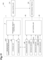
- the measuring unit 80 includes a body part 81, a unit controller 82 (see FIG. 11 ), a plurality of distance sensors 83X1, 83Y1, 83Y2, 83Z1, 83Z2, and 83Z3, mounting parts 84, support parts 85, and guide parts 86.
- the body part 81 is a flat plate-like member that supports the unit controller 82, the mounting parts 84, and the guide parts 86.
- the unit controller 82 is provided in a state of being supported by the body part 81 and performs various electrical processes in the measuring unit 80.
- Each of the distance sensors 83X1, 83Y1, 83Y2, 83Z1, 83Z2, and 83Z3 is a laser-type distance sensor, for example, and is attached to the mounting parts 84.
- the distance sensor 83X1 measures the distance to an object by emitting a laser beam toward the inside of the body part 81 along the X-axis direction.
- the distance sensors 83Y1 and 83Y2 measure the distances to an object by emitting laser beams toward the inside of the body part 81 along the Y-axis direction.
- the distance sensors 83Z1, 83Z2, and 83Z3 measure the distances to an object by emitting laser beams upward along the Z-axis direction.
- the mounting parts 84 are the portions on which each of the distance sensors 83X1, 83Y1, 83Y2, 83Z1, 83Z2, and 83Z3 is mounted, and are provided to stand on the body part 81.
- the support parts 85 are the portions that support the measured unit 90 and are provided to stand on the body part 81.
- the guide parts 86 are the portions that guide so that the measured unit 90 is positioned in a predetermined position when the measured unit 90 is supported on the support parts 85.
- the guide parts 86 are provided to stand on the body part 81.
- the measured unit 90 has a flange 91, a base plate 92, a plurality of target plates 93, 94, and 95, and legs 97.
- the flange 91 is the portion provided grippable by the gripper 12.
- the base plate 92 is connected to the flange 91, and the target plates 93, 94, and 95 are provided to stand thereon.
- the base plate 92 and the target plates 93, 94, and 95 are the portions forming the target surfaces to be measured by the respective distance sensors 83X1, 83Y1, 83Y2, 83Z1, 83Z2, and 83Z3.
- Each target plate 93, 94, and 95 is fixed in a predetermined place on the base plate 92.
- a surface 93a facing the distance sensor 83X1 in the target plate 93 is a plane perpendicular to the X-axis direction and has a predetermined positional relation with the reference position of the load port 300 (center position of the placement surface of the load port 300).
- a surface 94a facing the distance sensor 83Y1 in the target plate 94 and a surface 95a facing the distance sensor 83Y2 in the target plate 95 are planes perpendicular to the Y-axis direction and have a predetermined positional relation with the reference position of the load port 300.
- the legs 97 are provided at the bottom of each of the target plates 93, 94, and 95, and come into contact with the body part 81 of the measuring unit 80 when the measured unit 90 is supported by the measuring unit 80.
- the unit controller 82 of the measuring unit 80 can acquire the measurement distance X1 by the distance sensor 83X1, the measurement distance Y1 by the distance sensor 83Y1, the measurement distance Y2 by the distance sensor 83Y2, the measurement distance Z1 by the distance sensor 83Z1, the measurement distance Z2 by the distance sensor 83Z2, and the measurement distance Z3 by the distance sensor 83Z3. Then, the unit controller 82 can, based on a plurality of measurement distances X1, Y1, Y2, Z1, Z2, and Z3, calculate the actual position (X coordinate, Y coordinate, Z coordinate) of the grippers 12 with the reference position of the load port 300 as the origin, and the angle ⁇ , the angle ⁇ x, and the angle ⁇ y.
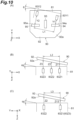
- the angle ⁇ is the rotation angle of the measuring unit 80 rotating about the Z-axis with respect to the measured unit 90 (that is, the rotation angle of the gripper 12 rotating about the Z-axis with respect to the load port 300).
- depiction of the distance sensors 83X1, 83Z1, 83Z2, 83Z3, and the like is omitted.
- the angle ⁇ x is the tilt angle of the measuring unit 80 inclined about the Y-axis with respect to a surface 92a of the base plate 92 of the measured unit 90 (that is, the tilt angle of the gripper 12 inclined about the Y-axis with respect to the reference plane of the load port 300).
- FIG. 10(B) depiction of the distance sensors 83X1, 83Y1, and 83Y2 and the target plates 93, 94, 95, and the like is omitted.
- the angle ⁇ y is the tilt angle of the measuring unit 80 inclined about the X-axis with respect to the surface 92a of the base plate 92 of the measured unit 90 (that is, the tilt angle of the gripper 12 inclined about the X-axis with respect to the reference plane of the load port 300).
- the state of the overhead transport vehicle 1 is acquired using the measuring units 80 placed on a first placement table 151, a second placement table 152, and a pair of third placement tables 153, 153 provided on a maintenance trestle 150 illustrated in FIG. 12(A) and FIG. 12(B) and using at least one measured unit 90.
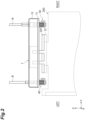
- the maintenance trestle 150 is described in detail. As illustrated in FIG. 12(A) , the maintenance trestle 150 is provided at a predetermined position along the track 20.
- the first placement table 151, the second placement table 152, and the pair of third placement tables 153, 153 are supported by a frame 154.
- the first placement table 151 is provided below the track 20 and at a relatively low position with respect to the second placement table 152 (in other words, at a position where the unwound amount of belts B for placing the FOUP 200 is relatively large).
- the second placement table 152 is provided below the track 20 and at a relatively high position with respect to the first placement table 151 (in other words, at a position where the unwound amount of belts B for placing the FOUP 200 is relatively small).
- the second placement table 152 is provided at a position displaced from the first placement table 151 (in the present embodiment, at a position displaced toward the rear) in a plan view seen from above in the vertical direction.
- the second placement table 152 is provided to be slidable in the front-and-rear direction and is provided to be movable between an advanced position at which it is located in the area above the first placement table 151 and a retracted position at which it is not located in the area above the first placement table 151.
- the second placement table 152 is moved to the advanced position.
- the pair of third placement tables 153, 153 are disposed so as to sandwich the track 20 in a plan view seen from above.
- the pair of third placement tables 153, 153 are provided at a position where the FOUP 200 cannot be transferred without activating the lateral unit 4.
- the pair of third placement tables 153, 153 are fixed immovably, unlike the second placement table 152.
- the state of the overhead transport vehicle 1 can be acquired for each of the first placement table 151, the second placement table 152, and the pair of third placement tables 153, 153.
- the state of the overhead transport vehicle 1 when the unwound amount of belts B is relatively large can be acquired using the first placement table 151
- the state of the overhead transport vehicle 1 when the unwound amount of belts B is relatively small can be acquired using the second placement table 152
- the state of the overhead transport vehicle 1 when the belts B are unwound by activating the lateral unit 4 can be acquired using the pair of third placement tables 153, 153.
- the area controller 110 causes the overhead transport vehicle 1 to move to the maintenance trestle 150 with predetermined timing.
- the area controller 110 (see FIG. 11 ) causes the overhead transport vehicle 1 to move to the maintenance trestle 150 according to a predetermined schedule (periodically).
- the measured unit 90 is placed in a state of being supported by the measuring unit 80 (see FIG. 8 ).
- the overhead transport vehicle 1 unwinds the belts B in a state of stopping above the first placement table 151 and lowers the holding unit 7. After unwinding the belts B by a predetermined amount, the overhead transport vehicle 1 activates the grippers 12 to grip the flange 91 of the measured unit 90. Thereafter, a predetermined amount of belts B is rewound and the measured unit 90 supported by the measuring unit 80 is separated from the measuring unit 80.
- the measuring unit 80 placed on the first placement table 151 measures, in this state, the distances X1, Y1, Y2, Z1, Z2, and Z3 to the base plate 92 and the target plates 93, 94, and 95 of the measured unit 90.
- the overhead transport vehicle 1 After the measurement by the measuring unit 80 placed on the first placement table 151, the overhead transport vehicle 1 winds the belts B in a state of gripping the measured unit 90, and moves the holding unit 7 to a height position higher than the second placement table 152.
- the second placement table 152 is slid and moved to the advanced position above the first placement table 151.
- the overhead transport vehicle 1 unwinds the belts B and lowers the holding unit 7 holding the measured unit 90.
- the overhead transport vehicle 1 unwinds the belts B by a predetermined amount and positions the measured unit 90 so as to be in a state of being separated by a predetermined amount from the measuring unit 80 placed on the second placement table 152.
- the measuring unit 80 placed on the second placement table 152 measures, in this state, the distances X1, Y1, Y2, Z1, Z2, and Z3 to the base plate 92 and the target plates 93, 94, and 95 of the measured unit 90.
- the overhead transport vehicle 1 After the measurement by the measuring unit 80 placed on the second placement table 152, the overhead transport vehicle 1 winds the belts B in a state of gripping the measured unit 90, and then, activates the lateral unit 4 to move the holding unit 7 above one of the pair of third placement tables 153. The overhead transport vehicle 1 unwinds the belts B and lowers the holding unit 7 holding the measured unit 90. The overhead transport vehicle 1 unwinds the belt B by a predetermined amount and positions the measured unit 90 so as to be in a state of being separated by a predetermined amount from the measuring unit 80 placed on the one of the pair of third placement tables 153.
- the measuring unit 80 placed on the one of the pair of third placement tables 153 measures, in this state, the distances X1, Y1, Y2, Z1, Z2, and Z3 to the base plate 92 and the target plates 93, 94, and 95 of the measured unit 90.
- the overhead transport vehicle 1 After the measurement by the measuring unit 80 placed on the one of the pair of third placement tables 153, the overhead transport vehicle 1 winds the belts B in a state of gripping the measured unit 90, activates the lateral unit 4, and this time, moves the holding unit 7 above the other of the pair of third placement tables 153. The overhead transport vehicle 1 unwinds the belts B and lowers the holding unit 7 holding the measured unit 90. The overhead transport vehicle 1 unwinds the belts B by a predetermined amount and positions the measured unit 90 so as to be in a state of being separated by a predetermined amount from the measuring unit 80 placed on the other of the pair of third placement tables 153.
- the measuring unit 80 placed on the other of the pair of third placement tables 153 measures, in this state, the distances X1, Y1, Y2, Z1, Z2, and Z3 to the base plate 92 and the target plates 93, 94, and 95 of the measured unit 90.
- the overhead transport vehicle 1 After the measurement by the measuring unit 80 placed on the other of the pair of third placement tables 153, the overhead transport vehicle 1 winds the belts B in a state of gripping the measured unit 90, activates the lateral unit 4, and this time, moves the holding unit 7 above the first placement table 151.
- the second placement table 152 moves to the retracted position retracted from above the first placement table 151.
- the move to the retracted position of the second placement table 152 may be performed at an appropriate timing after the measurement by the measuring unit 80 placed on the second placement table 152.
- the overhead transport vehicle 1 unwinds the belts B in a state of stopping above the first placement table 151 and lowers the holding unit 7 holding the measured unit 90. As illustrated in FIG. 15 , the overhead transport vehicle 1 unwinds the belts B until the measured unit 90 is in a state of being supported by the measuring unit 80 placed on the first placement table 151, then activates the grippers 12 to release the gripping of the flange 91 of the measured unit 90. The measured unit 90 is in a state of being supported by the measuring unit 80 placed on the first placement table 151. Thereafter, the overhead transport vehicle 1 winds the belts B until the holding unit 7 is ready to travel. The area controller 110 causes the overhead transport vehicle 1 to leave from the maintenance trestle 150.
- the communication unit 88 of the maintenance trestle 150 and the communication unit 9 of the overhead transport vehicle 1 can perform communication by appropriate means such as optical communication, wireless communication, and the like.
- the transport vehicle controller 8 causes the storage unit 8A (see FIG. 11 ) to store the information received via the communication unit 9 such as the actual position (X coordinate, Y coordinate, Z coordinate) of the grippers 12 with the reference position of each placement table as the origin, the angle ⁇ , the angle ⁇ x, and the angle ⁇ y. That is, the transport vehicle controller 8 causes the storage unit 8A to store (update) the latest state of the overhead transport vehicle 1 acquired by the measuring unit 80 and the measured unit 90. The transport vehicle controller 8 controls the operation of the linear motion mechanisms 67 based on the state of the overhead transport vehicle 1 stored in this storage unit 8A.
- the holding unit 7 is controlled based on predetermined set values when lifted or lowered, but in the transport vehicle system 100 of the above-described embodiment, the set values are appropriately corrected based on the measurement result acquired by the measuring unit 80 and the measured unit 90, that is, the information that is considered to be indicative of the current state of the holding unit 7 when the holding unit 7 is lifted or lowered to the transfer part, for example, the load port 300.
- This makes it possible to appropriately adjust the inclination of the holding unit 7 for each overhead transport vehicle 1 without human intervention
- the measured unit 90 is formed as a unit member grippable by the grippers 12, and the measuring unit 80 is formed as a unit member placeable on each of the placement tables of the maintenance trestle 150.
- the measured unit 90 is placed on the first placement table 151 in a state of being supported by the measuring unit 80. This makes it possible to rapidly execute automatic measurement by the measuring unit 80 and the measured unit 90.
- the measured unit 90 is used in a state of being gripped by the grippers 12, and the measuring unit 80 is used in a state of being placed on each of the placement tables of the maintenance trestle 150. This makes it possible to perform automatic measurement by the measuring unit 80 and the measured unit 90 without significantly changing the configuration of the overhead transport vehicle 1.
- the maintenance trestle 150 is provided in the traveling area of the overhead transport vehicle 1 separately from the load port 300, so that the overhead transport vehicle 1 can be measured efficiently without stopping the operation by the transport vehicle system 100.
- the maintenance trestle 150 including the first placement table 151, the second placement table 152, and the third placement tables 153 is provided, so that, on each of the load port 300 provided at a relatively low position with respect to the traveling position of the overhead transport vehicle 1, the load port 300 provided at a relatively high position, and the load port 300 on which placing is performed by operating the sliding part, it is possible to appropriately adjust the inclination of the holding unit 7 for each overhead transport vehicle 1.
- the overhead transport vehicle 1 is periodically moved to the maintenance trestle 150 and the measuring unit 80 is made to measure the measured unit 90, so that periodic adjustment of the set values can be made.
- the inclination of the holding unit 7 with respect to the horizontal plane can be adjusted.
- the amount of operation of the linear motion mechanisms 67 is automatically adjusted based on the information about the inclination on the holding unit 7 (information such as the angle ⁇ x and the angle ⁇ y) that is the state of the overhead transport vehicle 1, so that the holding unit 7 can be adjusted to the desired tilt. That is, the overhead transport vehicle 1 of the present embodiment can appropriately adjust the inclination of the holding unit 7 without human intervention.
- the holding unit 7 can be adjusted to the optimum inclination for each load port 300 on which the FOUP 200 is actually placed.
- the state of the overhead transport vehicle 1 may be acquired by moving the holding unit 7, which is gripping the measuring unit (first unit member) 80, away from or closer to the measured unit (second unit member) 90 placed on each of the placement tables.
- the measured unit 90 which is inexpensive relative to the measuring unit 80, is placed on each of the placement tables of the maintenance trestle 150, so that the maintenance trestle 150 can be constructed at a low cost.
- the state of the overhead transport vehicle 1 to be stored in the storage unit 8A with an example of the information such as the actual position (X coordinate, Y coordinate, Z coordinate) of the grippers 12 with a predetermined reference position as the origin, the angle ⁇ , the angle ⁇ x, the angle ⁇ y, and the like, but it may be set values of the amount of operation of the linear motion mechanisms 67 (amount of movement of the guide rollers) determined based on such information on the actual position (X coordinate, Y coordinate, Z coordinate), the angle ⁇ , the angle ⁇ x, the angle ⁇ y, and the like.
- the information such as the actual position (X coordinate, Y coordinate, Z coordinate) of the grippers 12 with a predetermined reference position as the origin, the angle ⁇ , the angle ⁇ x, the angle ⁇ y, and the like, but it may be set values of the amount of operation of the linear motion mechanisms 67 (amount of movement of the guide rollers) determined based on such information on the actual position (X coordinate, Y coordinate, Z coordinate),
- the measured unit 90 having the target plates 93, 94, and 95 which are measurement targets by the measuring unit 80, is disposed on each of the placement tables of the maintenance trestle 150, but in a case of the load port 300, for example, positioning pins or the like formed on a portion where the FOUP 200 is placed may be used, in place of the measured unit 90, as the measurement target of the measuring unit 80, or targets to be the measurement targets may be formed directly on each of the placement tables of the maintenance trestle 150.
- a cam mechanism position adjustment part having a similar function may be provided.
- the holding unit 7 of the above-described embodiment and the modifications has been described with an example in which one ends of the belts B are connected via the first buffering mechanism 50 and the second buffering mechanism 40, but it may be directly connected to the holding unit 7.
- the four belts B may be directly connected to the holding unit 7 as is.
- the three belts B may be connected to the holding unit 7.
- a measuring unit including a battery and a communication unit, which are integrally configured may be used.
Landscapes
- Engineering & Computer Science (AREA)
- Mechanical Engineering (AREA)
- Carriers, Traveling Bodies, And Overhead Traveling Cranes (AREA)
- Control And Safety Of Cranes (AREA)
- Warehouses Or Storage Devices (AREA)
- Container, Conveyance, Adherence, Positioning, Of Wafer (AREA)
- Loading Or Unloading Of Vehicles (AREA)
- Threshing Machine Elements (AREA)
- Control Of Vehicles With Linear Motors And Vehicles That Are Magnetically Levitated (AREA)
Applications Claiming Priority (2)
| Application Number | Priority Date | Filing Date | Title |
|---|---|---|---|
| JP2020191794 | 2020-11-18 | ||
| PCT/JP2021/035104 WO2022107448A1 (ja) | 2020-11-18 | 2021-09-24 | 搬送車システム |
Publications (3)
| Publication Number | Publication Date |
|---|---|
| EP4249405A1 true EP4249405A1 (de) | 2023-09-27 |
| EP4249405A4 EP4249405A4 (de) | 2024-12-04 |
| EP4249405B1 EP4249405B1 (de) | 2026-01-28 |
Family
ID=81708853
Family Applications (1)
| Application Number | Title | Priority Date | Filing Date |
|---|---|---|---|
| EP21894323.1A Active EP4249405B1 (de) | 2020-11-18 | 2021-09-24 | Transportfahrzeugsystem |
Country Status (8)
| Country | Link |
|---|---|
| US (1) | US12434907B2 (de) |
| EP (1) | EP4249405B1 (de) |
| JP (1) | JP7347692B2 (de) |
| KR (1) | KR102821026B1 (de) |
| CN (1) | CN116547220B (de) |
| IL (1) | IL302848B2 (de) |
| TW (1) | TWI870631B (de) |
| WO (1) | WO2022107448A1 (de) |
Families Citing this family (5)
| Publication number | Priority date | Publication date | Assignee | Title |
|---|---|---|---|---|
| WO2023203911A1 (ja) * | 2022-04-19 | 2023-10-26 | 村田機械株式会社 | 搬送システム |
| TWI861567B (zh) * | 2022-10-05 | 2024-11-11 | 張榮傑 | 自動倉儲台車搬運裝置 |
| JP7819677B2 (ja) * | 2023-06-09 | 2026-02-25 | 株式会社ダイフク | 検査装置 |
| CN117886118A (zh) * | 2024-02-27 | 2024-04-16 | 杭州海康机器人股份有限公司 | 一种搬运机器人和搬运机器人的上下料方法 |
| WO2026094474A1 (ja) * | 2024-11-01 | 2026-05-07 | 村田機械株式会社 | 天井搬送車システム及び保持ユニットの角度補正方法 |
Family Cites Families (18)
| Publication number | Priority date | Publication date | Assignee | Title |
|---|---|---|---|---|
| KR100194410B1 (ko) | 1996-03-19 | 1999-06-15 | 윤종용 | 전화기의 표시램프 불밝기 조절방법 |
| JPH10194410A (ja) | 1997-01-09 | 1998-07-28 | Toyota Autom Loom Works Ltd | 搬送台車における昇降ベルトの巻取構造及び搬送台車 |
| EP2790210A3 (de) * | 2002-06-19 | 2014-12-31 | Murata Machinery, Ltd. | Automatisiertes Materialhandhabungssystem |
| DE102007035839B4 (de) * | 2007-07-31 | 2017-06-22 | Globalfoundries Dresden Module One Limited Liability Company & Co. Kg | Verfahren und System zum lokalen Aufbewahren von Substratbehältern in einem Deckentransportsystem zum Verbessern der Aufnahme/Abgabe-Kapazitäten von Prozessanlagen |
| JP5266683B2 (ja) * | 2007-08-03 | 2013-08-21 | 村田機械株式会社 | 搬送システム、及び該搬送システムにおける教示方法 |
| JP5636849B2 (ja) * | 2010-09-30 | 2014-12-10 | 村田機械株式会社 | 移載システム |
| JP6191543B2 (ja) * | 2014-05-22 | 2017-09-06 | 株式会社ダイフク | 搬送装置 |
| JP6119699B2 (ja) * | 2014-08-27 | 2017-04-26 | 村田機械株式会社 | 移載位置決定方法 |
| JP6304084B2 (ja) * | 2015-03-16 | 2018-04-04 | 株式会社ダイフク | 物品搬送設備及び検査用治具 |
| JP6544434B2 (ja) * | 2015-08-28 | 2019-07-17 | 村田機械株式会社 | ティーチング装置、搬送システム、及び位置決めピンの測定方法 |
| JP6641926B2 (ja) * | 2015-11-26 | 2020-02-05 | 株式会社ダイフク | 物品搬送設備 |
| JP2017154840A (ja) | 2016-02-29 | 2017-09-07 | 株式会社ダイフク | 物品搬送設備 |
| EP3460834B1 (de) * | 2016-05-20 | 2020-08-05 | Murata Machinery, Ltd. | Transportfahrzeug und transportverfahren |
| KR102206058B1 (ko) * | 2016-06-27 | 2021-01-20 | 무라다기카이가부시끼가이샤 | 반송 시스템 |
| EP3670389B1 (de) * | 2017-08-16 | 2024-05-15 | Murata Machinery, Ltd. | Hochbahn-transportfahrzeug, hochbahn-transportsystem und steuerungsverfahren für ein hochbahn-transportfahrzeug |
| JP6784277B2 (ja) * | 2018-06-11 | 2020-11-11 | 村田機械株式会社 | ストッカ及び搬送車システム |
| SG11202106155VA (en) | 2018-12-14 | 2021-07-29 | Murata Machinery Ltd | Conveyance vehicle |
| CN114728743B (zh) * | 2019-11-20 | 2024-03-19 | 村田机械株式会社 | 空中搬送车 |
-
2021
- 2021-09-24 US US18/036,701 patent/US12434907B2/en active Active
- 2021-09-24 IL IL302848A patent/IL302848B2/en unknown
- 2021-09-24 WO PCT/JP2021/035104 patent/WO2022107448A1/ja not_active Ceased
- 2021-09-24 EP EP21894323.1A patent/EP4249405B1/de active Active
- 2021-09-24 JP JP2022563602A patent/JP7347692B2/ja active Active
- 2021-09-24 CN CN202180076467.2A patent/CN116547220B/zh active Active
- 2021-09-24 KR KR1020237019649A patent/KR102821026B1/ko active Active
- 2021-11-15 TW TW110142345A patent/TWI870631B/zh active
Also Published As
| Publication number | Publication date |
|---|---|
| CN116547220B (zh) | 2025-09-30 |
| IL302848A (en) | 2023-07-01 |
| US12434907B2 (en) | 2025-10-07 |
| EP4249405A4 (de) | 2024-12-04 |
| IL302848B2 (en) | 2026-03-01 |
| WO2022107448A1 (ja) | 2022-05-27 |
| KR102821026B1 (ko) | 2025-06-16 |
| KR20230104707A (ko) | 2023-07-10 |
| TWI870631B (zh) | 2025-01-21 |
| CN116547220A (zh) | 2023-08-04 |
| US20230406622A1 (en) | 2023-12-21 |
| JPWO2022107448A1 (de) | 2022-05-27 |
| IL302848B1 (en) | 2025-11-01 |
| JP7347692B2 (ja) | 2023-09-20 |
| TW202225061A (zh) | 2022-07-01 |
| EP4249405B1 (de) | 2026-01-28 |
Similar Documents
| Publication | Publication Date | Title |
|---|---|---|
| EP4249405B1 (de) | Transportfahrzeugsystem | |
| US12106992B2 (en) | Ceiling carrier | |
| US12540060B2 (en) | Overhead transport vehicle and transport vehicle system | |
| KR101305265B1 (ko) | 물품 반송 설비에 있어서의 학습 장치 및 학습 방법 | |
| US20170247190A1 (en) | Article Transport Facility | |
| KR102230179B1 (ko) | 스태커 크레인 | |
| WO2014115472A1 (ja) | 移載装置及び移載方法 | |
| US12522433B2 (en) | Overhead transport vehicle | |
| US20250229810A1 (en) | Overhead carrier vehicle | |
| WO2026094474A1 (ja) | 天井搬送車システム及び保持ユニットの角度補正方法 | |
| WO2023017655A1 (ja) | 天井搬送車システム | |
| KR101951091B1 (ko) | 코일 이송 장치 | |
| WO2025169533A1 (ja) | ティーチングユニット及び天井搬送車システム | |
| CN119461034A (zh) | 天车控制方法、系统及天车 |
Legal Events
| Date | Code | Title | Description |
|---|---|---|---|
| STAA | Information on the status of an ep patent application or granted ep patent |
Free format text: STATUS: THE INTERNATIONAL PUBLICATION HAS BEEN MADE |
|
| PUAI | Public reference made under article 153(3) epc to a published international application that has entered the european phase |
Free format text: ORIGINAL CODE: 0009012 |
|
| STAA | Information on the status of an ep patent application or granted ep patent |
Free format text: STATUS: REQUEST FOR EXAMINATION WAS MADE |
|
| 17P | Request for examination filed |
Effective date: 20230512 |
|
| AK | Designated contracting states |
Kind code of ref document: A1 Designated state(s): AL AT BE BG CH CY CZ DE DK EE ES FI FR GB GR HR HU IE IS IT LI LT LU LV MC MK MT NL NO PL PT RO RS SE SI SK SM TR |
|
| DAV | Request for validation of the european patent (deleted) | ||
| DAX | Request for extension of the european patent (deleted) | ||
| REG | Reference to a national code |
Ref country code: DE Ref legal event code: R079 Free format text: PREVIOUS MAIN CLASS: B65G0001040000 Ipc: H01L0021670000 Ref country code: DE Ref legal event code: R079 Ref document number: 602021047321 Country of ref document: DE Free format text: PREVIOUS MAIN CLASS: B65G0001040000 Ipc: H01L0021670000 |
|
| A4 | Supplementary search report drawn up and despatched |
Effective date: 20241107 |
|
| RIC1 | Information provided on ipc code assigned before grant |
Ipc: H01L 21/68 20060101ALI20241031BHEP Ipc: H01L 21/677 20060101ALI20241031BHEP Ipc: H01L 21/67 20060101AFI20241031BHEP |
|
| GRAP | Despatch of communication of intention to grant a patent |
Free format text: ORIGINAL CODE: EPIDOSNIGR1 |
|
| STAA | Information on the status of an ep patent application or granted ep patent |
Free format text: STATUS: GRANT OF PATENT IS INTENDED |
|
| INTG | Intention to grant announced |
Effective date: 20250904 |
|
| GRAS | Grant fee paid |
Free format text: ORIGINAL CODE: EPIDOSNIGR3 |
|
| GRAA | (expected) grant |
Free format text: ORIGINAL CODE: 0009210 |
|
| STAA | Information on the status of an ep patent application or granted ep patent |
Free format text: STATUS: THE PATENT HAS BEEN GRANTED |
|
| AK | Designated contracting states |
Kind code of ref document: B1 Designated state(s): AL AT BE BG CH CY CZ DE DK EE ES FI FR GB GR HR HU IE IS IT LI LT LU LV MC MK MT NL NO PL PT RO RS SE SI SK SM TR |
|
| REG | Reference to a national code |
Ref country code: CH Ref legal event code: F10 Free format text: ST27 STATUS EVENT CODE: U-0-0-F10-F00 (AS PROVIDED BY THE NATIONAL OFFICE) Effective date: 20260128 Ref country code: GB Ref legal event code: FG4D |
|
| REG | Reference to a national code |
Ref country code: DE Ref legal event code: R096 Ref document number: 602021047321 Country of ref document: DE |
|
| REG | Reference to a national code |
Ref country code: IE Ref legal event code: FG4D |