EP4249643A1 - Reduktionssystem und verfahren für hochschmelzende metalloxide mit flüssigmetalltiegel - Google Patents
Reduktionssystem und verfahren für hochschmelzende metalloxide mit flüssigmetalltiegel Download PDFInfo
- Publication number
- EP4249643A1 EP4249643A1 EP21894785.1A EP21894785A EP4249643A1 EP 4249643 A1 EP4249643 A1 EP 4249643A1 EP 21894785 A EP21894785 A EP 21894785A EP 4249643 A1 EP4249643 A1 EP 4249643A1
- Authority
- EP
- European Patent Office
- Prior art keywords
- metal
- raw material
- flux
- alloy
- oxide
- Prior art date
- Legal status (The legal status is an assumption and is not a legal conclusion. Google has not performed a legal analysis and makes no representation as to the accuracy of the status listed.)
- Pending
Links
Images


Classifications
-
- C—CHEMISTRY; METALLURGY
- C22—METALLURGY; FERROUS OR NON-FERROUS ALLOYS; TREATMENT OF ALLOYS OR NON-FERROUS METALS
- C22B—PRODUCTION AND REFINING OF METALS; PRETREATMENT OF RAW MATERIALS
- C22B9/00—General processes of refining or remelting of metals; Apparatus for electroslag or arc remelting of metals
- C22B9/10—General processes of refining or remelting of metals; Apparatus for electroslag or arc remelting of metals with refining or fluxing agents; Use of materials therefor, e.g. slagging or scorifying agents
-
- C—CHEMISTRY; METALLURGY
- C22—METALLURGY; FERROUS OR NON-FERROUS ALLOYS; TREATMENT OF ALLOYS OR NON-FERROUS METALS
- C22B—PRODUCTION AND REFINING OF METALS; PRETREATMENT OF RAW MATERIALS
- C22B34/00—Obtaining refractory metals
- C22B34/10—Obtaining titanium, zirconium or hafnium
- C22B34/12—Obtaining titanium or titanium compounds from ores or scrap by metallurgical processing; preparation of titanium compounds from other titanium compounds see C01G23/00 - C01G23/08
- C22B34/1263—Obtaining titanium or titanium compounds from ores or scrap by metallurgical processing; preparation of titanium compounds from other titanium compounds see C01G23/00 - C01G23/08 obtaining metallic titanium from titanium compounds, e.g. by reduction
- C22B34/1268—Obtaining titanium or titanium compounds from ores or scrap by metallurgical processing; preparation of titanium compounds from other titanium compounds see C01G23/00 - C01G23/08 obtaining metallic titanium from titanium compounds, e.g. by reduction using alkali or alkaline-earth metals or amalgams
-
- C—CHEMISTRY; METALLURGY
- C22—METALLURGY; FERROUS OR NON-FERROUS ALLOYS; TREATMENT OF ALLOYS OR NON-FERROUS METALS
- C22B—PRODUCTION AND REFINING OF METALS; PRETREATMENT OF RAW MATERIALS
- C22B34/00—Obtaining refractory metals
- C22B34/10—Obtaining titanium, zirconium or hafnium
- C22B34/12—Obtaining titanium or titanium compounds from ores or scrap by metallurgical processing; preparation of titanium compounds from other titanium compounds see C01G23/00 - C01G23/08
- C22B34/1263—Obtaining titanium or titanium compounds from ores or scrap by metallurgical processing; preparation of titanium compounds from other titanium compounds see C01G23/00 - C01G23/08 obtaining metallic titanium from titanium compounds, e.g. by reduction
- C22B34/1277—Obtaining titanium or titanium compounds from ores or scrap by metallurgical processing; preparation of titanium compounds from other titanium compounds see C01G23/00 - C01G23/08 obtaining metallic titanium from titanium compounds, e.g. by reduction using other metals, e.g. Al, Si, Mn
-
- C—CHEMISTRY; METALLURGY
- C22—METALLURGY; FERROUS OR NON-FERROUS ALLOYS; TREATMENT OF ALLOYS OR NON-FERROUS METALS
- C22B—PRODUCTION AND REFINING OF METALS; PRETREATMENT OF RAW MATERIALS
- C22B5/00—General methods of reducing to metals
- C22B5/02—Dry methods smelting of sulfides or formation of mattes
- C22B5/04—Dry methods smelting of sulfides or formation of mattes by aluminium, other metals or silicon
-
- C—CHEMISTRY; METALLURGY
- C22—METALLURGY; FERROUS OR NON-FERROUS ALLOYS; TREATMENT OF ALLOYS OR NON-FERROUS METALS
- C22B—PRODUCTION AND REFINING OF METALS; PRETREATMENT OF RAW MATERIALS
- C22B9/00—General processes of refining or remelting of metals; Apparatus for electroslag or arc remelting of metals
- C22B9/006—General processes of refining or remelting of metals; Apparatus for electroslag or arc remelting of metals with use of an inert protective material including the use of an inert gas
-
- C—CHEMISTRY; METALLURGY
- C22—METALLURGY; FERROUS OR NON-FERROUS ALLOYS; TREATMENT OF ALLOYS OR NON-FERROUS METALS
- C22B—PRODUCTION AND REFINING OF METALS; PRETREATMENT OF RAW MATERIALS
- C22B9/00—General processes of refining or remelting of metals; Apparatus for electroslag or arc remelting of metals
- C22B9/04—Refining by applying a vacuum
-
- C—CHEMISTRY; METALLURGY
- C22—METALLURGY; FERROUS OR NON-FERROUS ALLOYS; TREATMENT OF ALLOYS OR NON-FERROUS METALS
- C22B—PRODUCTION AND REFINING OF METALS; PRETREATMENT OF RAW MATERIALS
- C22B9/00—General processes of refining or remelting of metals; Apparatus for electroslag or arc remelting of metals
- C22B9/05—Refining by treating with gases, e.g. gas flushing also refining by means of a material generating gas in situ
-
- C—CHEMISTRY; METALLURGY
- C22—METALLURGY; FERROUS OR NON-FERROUS ALLOYS; TREATMENT OF ALLOYS OR NON-FERROUS METALS
- C22B—PRODUCTION AND REFINING OF METALS; PRETREATMENT OF RAW MATERIALS
- C22B9/00—General processes of refining or remelting of metals; Apparatus for electroslag or arc remelting of metals
- C22B9/14—Refining in the solid state
-
- C—CHEMISTRY; METALLURGY
- C25—ELECTROLYTIC OR ELECTROPHORETIC PROCESSES; APPARATUS THEREFOR
- C25C—PROCESSES FOR THE ELECTROLYTIC PRODUCTION, RECOVERY OR REFINING OF METALS; APPARATUS THEREFOR
- C25C3/00—Electrolytic production, recovery or refining of metals by electrolysis of melts
- C25C3/06—Electrolytic production, recovery or refining of metals by electrolysis of melts of aluminium
-
- C—CHEMISTRY; METALLURGY
- C25—ELECTROLYTIC OR ELECTROPHORETIC PROCESSES; APPARATUS THEREFOR
- C25C—PROCESSES FOR THE ELECTROLYTIC PRODUCTION, RECOVERY OR REFINING OF METALS; APPARATUS THEREFOR
- C25C3/00—Electrolytic production, recovery or refining of metals by electrolysis of melts
- C25C3/26—Electrolytic production, recovery or refining of metals by electrolysis of melts of titanium, zirconium, hafnium, tantalum or vanadium
- C25C3/28—Electrolytic production, recovery or refining of metals by electrolysis of melts of titanium, zirconium, hafnium, tantalum or vanadium of titanium
-
- C—CHEMISTRY; METALLURGY
- C25—ELECTROLYTIC OR ELECTROPHORETIC PROCESSES; APPARATUS THEREFOR
- C25C—PROCESSES FOR THE ELECTROLYTIC PRODUCTION, RECOVERY OR REFINING OF METALS; APPARATUS THEREFOR
- C25C3/00—Electrolytic production, recovery or refining of metals by electrolysis of melts
- C25C3/30—Electrolytic production, recovery or refining of metals by electrolysis of melts of manganese
-
- C—CHEMISTRY; METALLURGY
- C25—ELECTROLYTIC OR ELECTROPHORETIC PROCESSES; APPARATUS THEREFOR
- C25C—PROCESSES FOR THE ELECTROLYTIC PRODUCTION, RECOVERY OR REFINING OF METALS; APPARATUS THEREFOR
- C25C3/00—Electrolytic production, recovery or refining of metals by electrolysis of melts
- C25C3/32—Electrolytic production, recovery or refining of metals by electrolysis of melts of chromium
-
- C—CHEMISTRY; METALLURGY
- C25—ELECTROLYTIC OR ELECTROPHORETIC PROCESSES; APPARATUS THEREFOR
- C25C—PROCESSES FOR THE ELECTROLYTIC PRODUCTION, RECOVERY OR REFINING OF METALS; APPARATUS THEREFOR
- C25C3/00—Electrolytic production, recovery or refining of metals by electrolysis of melts
- C25C3/34—Electrolytic production, recovery or refining of metals by electrolysis of melts of metals not provided for in groups C25C3/02 - C25C3/32
-
- C—CHEMISTRY; METALLURGY
- C25—ELECTROLYTIC OR ELECTROPHORETIC PROCESSES; APPARATUS THEREFOR
- C25C—PROCESSES FOR THE ELECTROLYTIC PRODUCTION, RECOVERY OR REFINING OF METALS; APPARATUS THEREFOR
- C25C7/00—Constructional parts, or assemblies thereof, of cells; Servicing or operating of cells
- C25C7/005—Constructional parts, or assemblies thereof, of cells; Servicing or operating of cells of cells for the electrolysis of melts
-
- C—CHEMISTRY; METALLURGY
- C25—ELECTROLYTIC OR ELECTROPHORETIC PROCESSES; APPARATUS THEREFOR
- C25C—PROCESSES FOR THE ELECTROLYTIC PRODUCTION, RECOVERY OR REFINING OF METALS; APPARATUS THEREFOR
- C25C7/00—Constructional parts, or assemblies thereof, of cells; Servicing or operating of cells
- C25C7/06—Operating or servicing
Definitions
- the present disclosure relates to a system and a method for reducing a high-melting-point metal oxide using a liquid metal crucible.
- the metal M When a metal typically known in the art is referred to as any metal "M", the metal M may be obtained by reducing a raw material such as an oxide or halide.
- a method which is relatively well-known and most widely commonly used in the art, is the so-called Kroll process.
- the Kroll process may be summarized as a process in which molten magnesium is used as a reducing agent and a chloride of the desired metal M, such as titanium chloride or zirconium chloride, is added thereto and reduced to titanium or zirconium.
- a chloride of the desired metal M such as titanium chloride or zirconium chloride
- this Kroll process is a process that uses chloride as a raw material, chlorine gas and magnesium chloride are generated as by-products during the process.
- chlorine gas is regarded as a representative problem of the Kroll process, which is an environmental problem that causes fatal problems to the human body, and magnesium chloride causes process problems such as rapid corrosion of reaction vessels called cells, melting furnaces or crucibles or the like.
- the Kroll process requires an additional device to overcome environmental regulations, and involves frequent replacement of reaction vessels, resulting in high costs for operating the process.
- the metal obtained through the Kroll is in the form of a sponge including a large number of pores, and thus it is very difficult to control oxygen that may exist in the metal.
- the Kroll process has limitations in obtaining high-purity metals.
- the above method has a problem in that a reducing agent having strong reducing power directly contacts a portion of the reactor due to the characteristics of the process system, causing corrosion of the reaction vessel, similar to the Kroll process.
- An object of the present disclosure is to provide a technology capable of overcoming the above-described problems.
- the present disclosure provides a system optimized for obtaining a desired metal from a metal oxide without using a metal chloride or using chloride as an flux, and a method capable of producing this metal. Accordingly, the present disclosure is capable of resolving the environmental problems of the above-described Kroll process and the cost problems caused by cell corrosion.
- the present disclosure provides a technology capable of obtaining a large amount of high-purity metal while facilitating the operation of the process according to the following aspects.
- a system and method provided in the present disclosure are characterized by using a liquid metal crucible that includes a liquid metal alloy of metal M 1 and metal M 2 forming a eutectic phase with each other.
- liquid metal crucible may significantly reduce energy consumption, leading to cost reduction. This because when a metal oxide included in a raw material module is reduced to metal M 1 , the melting point of metal M 1 is lowered by a eutectic reaction so that electrolytic reduction may be effectively performed at a relatively low temperature.
- a liquid alloy (M 1 and M 2 form a liquid metal alloy) is obtained by a eutectic reaction, and thus the metal alloy itself may be used as a final product. Since the final product derived from such a liquid alloy has a significantly smaller specific surface area that may be in contact with oxygen than the sponge-type product of the Kroll process, the system and method of the present disclosure may minimize the problem of oxygen contamination of the product.
- metal M 1 may be obtained by electrorefining the obtained metal alloy.
- the liquid alloy thus obtained may be completely isolated from an environment in which oxygen may exist, and thus contamination thereof by oxygen may be significantly prevented. That is, according to the above aspect, it is possible to obtain a high-purity metal alloy and metal M 1 .
- raw materials for example, an oxide containing a desired metal, a reducing agent, and an alloying metal
- the system and method are characterized by using such a raw material module.
- the raw materials are likely to be oxidized or contaminated with oxygen before being introduced.
- the raw material module according to the present disclosure includes a structure treated to be prevented from oxidation, and thus has a more enhanced oxygen barrier effect compared to the Kroll process. Accordingly, the metal alloy and metal obtained according to the present disclosure may have a remarkably low oxygen content. In other words, according to the present disclosure, it is possible to obtain a high-purity metal alloy and metal having little oxygen.
- a system for reducing a metal oxide to metal M 1 is provided.
- the system may further include an electrorefining part configured to collect and electrorefine the liquid metal alloy formed by the reduced metal M 1 and metal M 2 to obtain metal M 1 .
- the metal oxide may include at least one selected from the group consisting of M 1 x O z and M 1 x M 3 y O z , wherein x and y are each a real number ranging from 1 to 3, and z is a real number ranging from 1 to 4.
- the solid raw material module may include: a core layer including the metal oxide and the reducing metal M 3 ; and a shell layer composed of metal M 2 surrounding the core layer.
- the solid raw material module may be a multilayer structure including: a core layer including the metal oxide; and a shell layer coated to surround the outer surface of the core layer, wherein the shell layer may include an alloy phase composed of metal M 2 and metal M 3 .
- the solid raw material module may be configured to descend vertically within the cell until it reaches the liquid metal crucible through the flux, and the solid raw material module may descend at a rate of a distance corresponding to 0.1% to 10% of the depth of the cell per min.
- oxide M 3 a O b when the metal oxide is reduced to metal M 1 by reaction with reducing metal M 3 while the solid raw material module is melted, oxide M 3 a O b may be produced, and the oxide M 3 a O b may have a lower specific gravity than that of the flux.
- a and b are each a real number ranging from 1 to 3.
- the oxide M 3 a O b may float on the flux due to a density difference to form a by-product layer.
- the liquid metal alloy may be continuously collected through the bottom of the cell, and the by-product layer may be continuously collected through the top of the cell, thereby enabling a continuous process.
- system may further include a recycling part configured to collect the byproduct layer and mix the same with M 1 x O z to produce M 1 x M 3 y O z .
- the reaction between the metal oxide and the reducing metal may be performed in an inert gas atmosphere and/or air.
- the core layer may be composed of a powder mixture including the metal oxide powder and the reducing metal M 3 powder.
- the core layer may have a multilayer structure including: a first core composed of the metal oxide; and a second core coated to surround the outer surface of the first core and composed of metal M 3 .
- the solid raw material module may further include an oxidation-preventing layer surrounding the shell layer and serving to prevent oxidation of metal included in the core layer and/or the shell layer.
- the oxidation-preventing layer may include at least one selected from the group consisting of LiF, MgF 2 , CaF 2 , BaF 2 , CaCl 2 , MgCl 2 , MgO, CaO, BaO, Al 2 O 3 and SiO 2 .
- metal M 1 may be one selected from the group consisting of Ti, Zr, Hf, W, Fe, Ni, Zn, Co, Mn, Cr, Ta, Ga, Nb, Sn, Ag, La, Ce, Pr, Nd, Nb, Pm, Sm, Eu, Al, V, Mo, Gd, Tb, Dy, Ho, Er, Tm, Yb, Ac, Th, Pa, U, Np, Pu, Am, Cm, Bk, Cf, Es, Fm, Md and No, metal M 2 may be at least one selected from the group consisting of Cu, Ni, Fe, Sn, Zn, Pb, Bi, Cd, and alloys thereof, and metal M 3 may be at least one selected from the group consisting of Ca, Mg, Al, and alloys thereof.
- a method of reducing and refining a metal oxide to metal M 1 is provided.
- oxide M 3 a O b may be produced as a by-product in moving the solid raw material module and/or obtaining the liquid metal alloy, and the oxide M 3 a O b may have a lower specific gravity than that of the flux, and the method may further include continuously collecting the by-product M 3 a O b forming a layer on the flux, and adding and mixing M 1 x O z with the collected M 3 a O b , thereby producing a metal oxide expressed as M 1 x M 3 y O z derived from the by-product M 3 a O b and the added M 1 x O z .
- three is provided a metal alloy or metal produced by the method according to the above-described example embodiment, wherein the metal alloy may have a residual reducing metal M 3 content of 0.1 wt% or less, specifically 0.01 wt% or less, more specifically 0.001 wt% or less, based on the total weight of the metal alloy, and an oxygen content of 1,200 ppm or less, specifically 1,000 ppm or less, more specifically 990 ppm or less.
- the present disclosure provides a system optimized for obtaining a desired metal from a metal oxide without using a metal chloride or using chloride as an flux, and a method for producing this metal. Accordingly, the present disclosure is capable of resolving the environmental problems of the above-described Kroll process and the cost problems caused by cell corrosion.
- the system and method provided in the present disclosure are characterized by using a liquid metal crucible that includes a liquid metal alloy of metal M 1 and metal M 2 forming a eutectic phase with each other.
- a liquid metal crucible may significantly reduce energy consumption, leading to cost reduction. This because when a metal oxide included in a module, which is a raw material, is reduced to metal M 1 , the melting point of metal M 1 is lowered by a eutectic reaction so that electrolytic reduction may be effectively performed at a relatively low temperature.
- a liquid alloy (M 1 and M 2 form a liquid metal alloy) is obtained by a eutectic reaction, and thus the metal alloy itself may be used as a final product. Since the final product derived from such a liquid alloy has a significantly smaller specific surface area that may be in contact with oxygen than the sponge-type product of the Kroll process, the system and method of the present disclosure may minimize the problem of oxygen contamination of the product.
- the liquid alloy thus obtained may be completely isolated from an environment in which oxygen may exist, and thus contamination thereof by oxygen may be significantly prevented. That is, according to the foregoing, it is possible to obtain a high-purity metal alloy and metal M 1 .
- raw materials for example, an oxide containing a desired metal, a reducing agent, and an alloying metal
- the system and method are characterized by using such a raw material module.
- the raw materials are likely to be oxidized or contaminated with oxygen before being introduced.
- the raw material module according to the present disclosure includes a structure treated to be prevented from oxidation, and thus has a more enhanced oxygen barrier effect compared to the Kroll process. Accordingly, the metal alloy and metal obtained according to the present disclosure may have a remarkably low oxygen content. In other words, according to the present disclosure, it is possible to obtain a high-purity metal alloy and metal having little oxygen.
- charging as used in the present specification may be used interchangeably with the term “feeding”, “introducing”, “flowing in”, or “injection”, and may be understood to mean sending or putting any material, such as a raw material, into a place where it is needed.
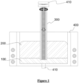
- a system for a metal oxide to metal M 1 according to the present disclosure is schematically shown in FIG. 1 .
- the system according to the present disclosure may include:
- the desired metal M 1 is not particularly limited, but may be specifically one selected from the group consisting of Ti, Zr, Hf, W, Fe, Ni, Zn, Co, Mn, Cr, Ta, Ga, Nb, Sn, Ag, La, Ce, Pr, Nd, Nb, Pm, Sm, Eu, Al, V, Mo, Gd, Tb, Dy, Ho, Er, Tm, Yb, Ac, Th, Pa, U, Np, Pu, Am, Cm, Bk, Cf, Es, Fm, Md and No.
- the desired metal M 1 may be one selected from the group consisting of Ti, Zr, W, Fe, Ni, Zn, Co, Mn, Cr, Ta, Er and No, and more specifically, may be one selected from the group consisting of Ti, Zr, W, Fe, Ni, Zn, Co, Mn, and Cr. Even more specifically, it may be Ti, Zr or W.
- metal M 2 is not particularly limited as long as it can form a liquid metal alloy by a eutectic reaction with metal M 1 .
- metal M 2 may be at least one selected from the group consisting of Cu, Ni, Fe, Sn, Zn, Pb, Bi, Cd, and alloys thereof, and more specifically, may be Cu, Ni, or an alloy thereof.
- metal M 3 is not particularly limited as long as it can reduce the metal oxide to M 1 .
- metal M 3 may be at least one selected from among Ca, Mg, Al, and alloys thereof, and more specifically, may be Ca or Mg, in particular, Mg.
- the metal oxide may include at least one selected from the group consisting of M 1 x O z and M 1 x M 3 y O z , wherein x and y are each a real number ranging from 1 to 3, and z is a real number ranging from 1 to 4.
- the metal oxide may include one or a combination of two or more selected from the group consisting of ZrO 2 , TiO 2 , MgTiO 3 , HfO 2 , Nb 2 O 5 , Dy 2 O 3 , Tb 4 O 7 , WO 3 , Co 3 O 4 , MnO, Cr 2 O 3 , MgO, CaO, Al 2 O 3 , Ta 2 O 5 , Ga 2 O 3 , Pb 3 O 4 , SnO, NbO and Ag 2 O, without being limited thereto.
- the system according to the present disclosure is different from the conventional Kroll process in that it uses a metal oxide instead of a metal chloride as a raw material.
- Raw materials usually found in nature include an oxide of metal M 1 , and in order to use this metal oxide in the Kroll process, a pretreatment process of substituting the metal oxide with a chloride needs to be performed. If this pretreatment process is performed, it itself will cause an increase in process cost.
- hydrochloric acid is used in the pretreatment process of substituting the metal oxide with a chloride, and in this case, corrosion of production equipment may be promoted due to the strong acidity of the hydrochloric acid, and toxic chlorine gas may be generated during the process, which may cause environmental problems.
- the system according to the present disclosure has advantages over the Kroll process in that it does not require the pretreatment process of substituting the metal oxide with a chloride, and thus it incurs a lower cost than the Kroll process cost and does not cause environmental problems.
- the cell 400 is preferably made of a material that has a high melting point in terms of durability and does not cause side reactions with the flux and the liquid metal crucible.
- the material of the cell may include at least one selected from the group consisting of MgO, Cr 2 O 3 , Al 2 O 3 , SiO 2 , CaO, SiC, WO 3 , W, C, and Mo, without being limited thereto.
- the cell 400 may include a tapping hole 410 for continuously tapping the liquid metal alloy produced at the bottom thereof.
- liquid metal crucible may refer to a reaction region capable of providing an environment in which at least one metal may be accommodated in, for example, the cell in a molten state while forming one layer, and the raw material module of the present disclosure may be melted within and the layer surface of the melted metal so that the metal oxide may be reduced.
- the system according to the present disclosure has the advantage of using this liquid metal crucible.
- melting point of metal M 1 may be lowered by the eutectic reaction while the metal oxide of the raw material module is reduced to metal M 1 , and thus electrolytic reduction may be effectively performed at a relatively low temperature. That is, in the system of the present disclosure, it is possible to obtain a liquid metal alloy while operating a liquid metal crucible in which metals are melted, and it is possible to operate the process at a lower temperature than the melting point of metal M 1 , thereby significantly reducing energy consumption. This temperature may vary depending on the types of M 1 and M 2 , but may preferably be 900°C to 1,600°C.
- a liquid alloy (M 1 and M 2 form a liquid metal alloy) may be obtained based on the eutectic reaction induced in the system of the present disclosure, and the metal alloy itself may be used as a final product.
- M 1 is often used industrially in the form of an alloy.
- a post-processing process for forming an alloy with another metal may be required.
- the present disclosure has high process efficiency in that it is possible to obtain a final product in the form of a metal alloy of M 1 and M 2 through reduction reaction without the above-described post-treatment process.
- metal M 1 may be obtained by electrorefining the obtained metal alloy, and a method known in the art may be used for such electrolytic refining.
- the liquid alloy obtained according to the present disclosure may be completely isolated from an environment in which oxygen may exist, and thus contamination thereof by oxygen may be significantly prevented. That is, according to the above aspect, it is possible to obtain a high-purity metal alloy and metal M 1 .
- the use of the liquid metal crucible including the liquid metal alloy of metal M 1 and metal M 2 forming a eutectic phase with each other has an advantage in that, even if the metal oxide contained in the raw material module is a material that is difficult to electrolytically reduce to metal, it is possible to more easily reduce the metal oxide in the raw material module using the standard oxidation-reduction potential difference between the liquid metal alloy and the desired metal M 1 . That is, when metal M 2 having a more positive standard reduction potential that of metal M 1 is used, the standard reduction potential value of M 1 may move in a positive direction due to the liquid metal crucible, so that electrolytic reduction of the metal may be more easily achieved.
- a metal oxide as a raw material, another metal as a reducing agent, and other additive metals are not introduced, but they constitute a raw material module like a single part, and based on this raw material module, it is possible to obtain a higher-quality metal alloy and metal.
- the raw materials are likely to be oxidized before being introduced, but the raw material module according to the present disclosure includes a structure treated to be prevented from oxidation, and thus has a more enhanced oxygen barrier effect compared to the Kroll process. Accordingly, the metal alloy and metal obtained according to the present disclosure may have a significantly low oxygen content.
- the system of the present disclosure includes a configuration for doubly blocking oxygen, because the flux serves as a barrier layer for blocking oxygen, and the raw material module itself can also block oxygen. Accordingly, the system of the present disclosure has significant advantages in that it is possible to perform the reaction between the metal oxide and the reducing metal under an inert gas atmosphere, which has been commonly recognized in the art, and it is also possible to perform the reaction between the metal oxide and the reducing metal in air. Even if the system of the present disclosure is operated in air, the metal alloy and metal produced thereby are of high purity with little oxygen. This will be clearly demonstrated through examples to be described later. In some cases, in the system of the present disclosure, the reaction between the metal oxide and the reducing metal may be performed in a combination of an inert gas atmosphere and a normal air atmosphere.
- the system of the present disclosure uses a raw material module in which raw materials necessary for the reaction are gathered into one body, and thus has an advantage in that it is easy to induce the reaction at the most optimal location in the cell.
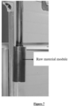
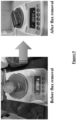
- FIG. 2 Photographs showing a process of preparing a raw material module according to the present disclosure are depicted in FIG. 2
- FIG. 4 shows a schematic view of a raw material module according to one example embodiment of the present disclosure.
- the photographs shown in FIG. 2 are only for helping understanding of the preparation of the raw material module as a non-limiting example, and the scope of the present disclosure is not limited thereto.
- the solid raw material module 300 may include: a core layer 30 including the metal oxide 10 and the reducing metal M 3 30; and a shell layer 320 composed of metal M 2 surrounding the core layer 310.
- the core layer 310 may have a multilayer structure including: a first core 311 composed of the metal oxide 10; and a second core 312 coated to surround the outer surface of the first core 311 and composed of the reducing metal M 3 30.
- a raw material module 300a as shown in FIG. 5 in which a core layer is shown as another example of the present disclosure may be used.
- the core layer 310a of the raw material module 300a may be composed of a powdery mixture including metal oxide powder 10a and reducing metal M 3 powder 30a.
- the structure shown in FIG. 6 may also be preferable as the raw material module.
- the raw material module 300b is similar to the above-described example in terms of a multilayer structure, but is different from the above-described example in that it includes the core layer 310b including the metal oxide 10b and the shell layer 320b coated to surround the outer surface of the core layer 310b, wherein the shell layer 320b is a coating layer including an alloy phase 330b composed of the metal M 2 20b and the metal M 3 30b.
- the above-described solid raw material module may further include an oxidation-preventing layer (330 in FIG. 4 ) surrounding the shell layer and serving to prevent oxidation of metal included in the core layer and/or the shell layer by blocking oxygen from contacting the metal.
- the oxidation-preventing layer 330 may include at least one selected from the group consisting of LiF, MgF 2 , CaF 2 , BaF 2 , CaCl 2 , MgCl 2 , MgO, CaO, BaO, Al 2 O 3 and SiO 2 , but the scope of the present disclosure is not limited thereto.
- the oxidation-preventing layer is shown only in FIG. 4 , it is to be understood that the oxidation-preventing layer may also be applied to the other example embodiments shown in FIGS. 5 and 6 .
- This solid raw material module may be configured to descend vertically within the cell until it reaches the liquid metal crucible through the flux.
- the solid raw material module may descend at a rate of a distance corresponding to 0.1% to 10% of the depth of the cell per min.
- rotating the solid raw material module about the axis is preferable in terms of stirring the liquid metal crucible and improving reactivity thereby.
- the rotation may be performed during the descent into the cell and/or until completion of the descent.
- system according to the present disclosure may further include a rotation unit to which the solid raw material module is mounted and which rotates the same.
- the solid raw material module descends to the liquid metal crucible and is melted, and at the same time or partially simultaneously, the metal oxide and the reducing metal M 3 react to reduce the metal oxide to M 1 , and the reduced M 1 forms a liquid metal alloy with M 2 contained in the solid raw material module.
- the metal oxide (M 1 x O z ) is TiO 2
- M 2 is Ni
- M 3 is Mg
- Reaction Formulas 1-1 and 1-2 below the metal oxide may be reduced to metal Ti, and then an M 3 oxide (M 3 a O b ) may be separated while the liquid metal alloy TiNi is obtained.
- Reaction Formula 1-1 2Mg + TiO 2 -> Ti + 2MgO
- Reaction Formula 1-2 Ti + Ni + 2MgO ⁇ TiNi (alloy) + 2MgO (separated)
- the metal oxide (M 1 x M 3 y O z ) is MgTiO 3
- M 2 is Ni
- M 3 is Mg
- Reaction Formulas 2-1 and 2-2 below the metal oxide may be reduced to metal Ti, and then an M 3 oxide (M 3 a O b ) may be separated while the liquid metal alloy TiNi is obtained.
- M 3 aO b produced according to the above-described reaction is a kind of by-product and may have a lower specific gravity that that of the flux of the present disclosure.
- the M 3 a O b may float on the flux due to its density difference from the flux to form a by-product layer. Therefore, the by-product M 3 a O b does not mix with the liquid metal crucible present as a layer under the flux and with the formed liquid metal alloy.
- the by-product layer may serve to prevent the flux from being lost by vaporization while being positioned on the flux, and to prevent oxygen in the air from penetrating into the reactor.
- the system according to the present disclosure may be configured to enable a continuous process by using this by-product.
- the system of the present disclosure may further include a recycling device that continuously collects the layered by-product floating on the flux through the top of the cell and mixes the collected by-product with, for example, M 1 x O z to produce metal oxide M 1 x M 3 y O z .
- M 1 x O z the reduction reaction rate may be further increased compared to when M 1 x O z is used.
- the flux preferably has a specific gravity which is intermediate between the specific gravity of the liquid metal crucible and the specific gravity of the by-product M 3 a O b so as to prevent the liquid metal crucible and the by-product M 3 a O b from mixing with each other, and at the same time, the flux is preferably insoluble in the by-product M 3 a O b .
- the flux is preferably a material such as a non-chlorine-based material, which does not cause environmental problems while being capable of preventing prevent oxygen from penetrating into the liquid metal crucible and the liquid metal alloy containing the desired metal M 1 .
- This flux may include a molten halide salt of at least one metal selected from the group consisting of alkali metals and alkaline earth metals, but does not contain chloride. More specifically, the flux in the system of the present disclosure may be a molten halide salt of at least one metal selected from the group consisting of alkali metals including Li, Na, K, Rb, and Cs, and alkaline earth metals including Mg, Ca, Sr, and Ba. In this case, the halide may include fluoride, bromide, iodide, or a mixture thereof.
- the flux may also be present in an amount of 10 wt% to 50 wt%, specifically 10 wt% to 20 wt%, more specifically 10 wt% to 15 wt%, even more specifically 12 wt% to 13 wt%, relative to the metal oxide involved in the overall reduction reaction, that is, the metal oxide contained in the raw material module and capable of being reduced to the desired metal M 1 .
- the flux may further contain, as an additive, at least one metal oxide selected from the group of alkali metals and alkaline earth metals.
- the content of the additive may be 0.1 to 25 wt% based on the total weight of the flux.
- the additive may include Li 2 O, Na 2 O, SrO, Cs 2 O, K 2 O, CaO, BaO, or a mixture thereof, without being limited thereto.
- the additive contained in the flux may enable easier reduction of the metal oxide contained in the raw material module.
- the system according to the present disclosure may further include an electrorefining part configured to continuously collect the liquid metal alloy formed by M 1 and M 2 through the bottom of the cell and to electrorefine the collected liquid metal alloy to obtain metal M 1 .
- the electrorefining part may solidify the collected liquid metal alloy to obtain a solid metal alloy, and electrorefine the solid metal alloy, thereby recovering metal M 1 from the metal alloy.
- an flux that may remain in the liquid metal alloy may be removed before electrorefining of the solid metal alloy, and this removal may be achieved, for example, by heat-treating the liquid metal alloy in a vacuum or inert gas atmosphere, causing the flux to be removed by distillation.
- the distillation temperature heat treatment temperature
- the distillation temperature is not particularly limited as long as it is a temperature equal to or higher than the melting point of the flux used in the system of the present disclosure, and it may be, for example, 780 to 1,000°C.
- the electrorefining part may include an flux including a molten halide salt of at least one metal selected from the group consisting of alkali metals and alkaline earth metals, independently of the flux used in the above-described reduction reaction.
- the method according to the present disclosure may include the operations of:
- the metal oxide and the reducing metal M 3 may react with each other to reduce the metal oxide to metal M 1 , and the reduced metal M 1 and metal M 2 may be continuously incorporated into the liquid metal crucible while forming a liquid metal alloy.
- the desired metal M 1 is not particularly limited, but may be specifically one selected from the group consisting of Ti, Zr, Hf, W, Fe, Ni, Zn, Co, Mn, Cr, Ta, Ga, Nb, Sn, Ag, La, Ce, Pr, Nd, Nb, Pm, Sm, Eu, Al, V, Mo, Gd, Tb, Dy, Ho, Er, Tm, Yb, Ac, Th, Pa, U, Np, Pu, Am, Cm, Bk, Cf, Es, Fm, Md and No.
- the desired metal M 1 may be one selected from the group consisting of Ti, Zr, W, Fe, Ni, Zn, Co, Mn, Cr, Ta, Er and No, and more specifically, may be one selected from the group consisting of Ti, Zr, W, Fe, Ni, Zn, Co, Mn, and Cr. Even more specifically, it may be Ti, Zr or W.
- metal M 2 is not particularly limited as long as it can form a liquid metal alloy by a eutectic reaction with metal M 1 .
- metal M 2 may be at least one selected from the group consisting of Cu, Ni, Fe, Sn, Zn, Pb, Bi, Cd, and alloys thereof, and more specifically, may be Cu, Ni, or an alloy thereof.
- metal M 3 is not particularly limited as long as it can reduce the metal oxide to M 1 .
- metal M 3 may be at least one selected from among Ca, Mg, Al, and alloys thereof, and more specifically, may be Ca or Mg, in particular, Mg.
- the metal oxide may include at least one selected from the group consisting of M 1 x O z and M 1 x M 3 y O z , wherein x and y are each a real number ranging from 1 to 3, and z is a real number ranging from 1 to 4.
- the metal oxide may include one or a combination of two or more selected from the group consisting of ZrO 2 , TiO 2 , MgTiO 3 , HfO 2 , Nb 2 O 5 , Dy 2 O 3 , Tb 4 O 7 , WO 3 , Co 3 O 4 , MnO, Cr 2 O 3 , MgO, CaO, Al 2 O 3 , Ta 2 O 5 , Ga 2 O 3 , Pb 3 O 4 , SnO, NbO and Ag 2 O, without being limited thereto.
- the method according to the present disclosure is different from the conventional Kroll process in that it uses a metal oxide instead of a metal chloride as a raw material.
- Raw materials usually found in nature include an oxide of metal M 1 , and in order to use this metal oxide in the Kroll process, a pretreatment process of substituting the metal oxide with a chloride needs to be performed. If this pretreatment process is performed, it itself will cause an increase in process cost.
- hydrochloric acid is used in the pretreatment process of substituting the metal oxide with a chloride, and in this case, corrosion of production equipment may be promoted due to the strong acidity of the hydrochloric acid, and toxic chlorine gas may be generated during the process, which may cause environmental problems.
- the method according to the present disclosure has advantages over the Kroll process in that it does not require the pretreatment process of substituting the metal oxide with a chloride, and thus it incurs a lower cost than the Kroll process cost and does not cause environmental problems.
- the raw material module that is used in the method of the present disclosure may include: a core layer including a metal oxide and reducing metal M 3 ; and a shell layer composed of metal M 2 surrounding the core layer.
- the core layer 310 may have a multilayer structure including: a first core composed of the metal oxide; and a second core coated to surround the outer surface of the first core and composed of the reducing metal M 3 .
- the core layer 310a of the raw material module 300a may be composed of a powdery mixture including metal oxide powder and reducing metal M 3 powder.
- the raw material module shown in FIG. 6 may also be used.
- This raw material module may include the core layer including the metal oxide and the shell layer coated to surround the outer surface of the core layer, wherein the shell layer may be a coating layer including an alloy phase composed of metal M 2 and metal M 3 .
- the solid raw material module may further include an oxidation-preventing layer surrounding the shell layer and serving to prevent oxidation of metal included in the core layer and/or the shell layer by blocking oxygen from contacting the metal.
- the oxidation-preventing layer may include at least one selected from the group consisting of LiF, MgF 2 , CaF 2 , BaF 2 , CaCl 2 , MgCl 2 , MgO, CaO, BaO, Al 2 O 3 and SiO 2 , but the scope of the present disclosure is not limited thereto.
- the solid raw material module may be descended at a rate of a distance corresponding to 0.1% to 10% of the depth of the cell per min, until it reaches the liquid metal crucible through the flux.
- the metal oxide may be reduced to metal M 1 by reaction with the reducing metal M 3 , and the reduced M 1 may form a liquid metal alloy with the metal M 2 contained in the solid raw material module.
- the metal oxide (M 1 x O z ) is TiO 2
- M 2 is Ni
- M 3 is Mg
- Reaction Formulas 1-1 and 1-2 below the metal oxide may be reduced to metal Ti, and then an M 3 oxide (M 3 a O b ) may be separated while the liquid metal alloy TiNi is obtained.
- Reaction Formula 1-1 2Mg + TiO 2 -> Ti + 2MgO
- Reaction Formula 1-2 Ti + Ni + 2MgO ⁇ TiNi (alloy) + 2MgO (separated)
- the metal oxide (M 1 x M 3 y O z ) is MgTiO 3
- M 2 is Ni
- M 3 is Mg
- Reaction Formulas 2-1 and 2-2 below the metal oxide may be reduced to metal Ti, and then an M 3 oxide (M 3 a O b ) may be separated while the liquid metal alloy TiNi is obtained.
- M 3 aO b produced according to the above-described reaction is a kind of by-product and may have a lower specific gravity that that of the flux of the present disclosure.
- the M 3 a O b may float on the flux due to its density difference from the flux to form a by-product layer. Therefore, the by-product M 3 a O b does not mix with the liquid metal crucible present as a layer under the flux and with the formed liquid metal alloy.
- the by-product layer may serve to prevent the flux from being lost by vaporization while being positioned on the flux, and to prevent oxygen in the air from penetrating into the reactor.
- the method according to the present disclosure may be configured to use this by-product.
- the method according to the present disclosure may further include the operation of continuously collecting the layered by-product (i.e., M 3 a O b ) floating on the flux through the top of the cell, and adding and mixing, for example, M 1 x O z with the collected M 3 a O b , thereby producing the metal oxide M 1 x M 3 y O z derived from the by-product M 3 a O b and the added M 1 x O z .
- M 3 a O b the layered by-product floating on the flux through the top of the cell
- the reduction reaction rate may be further increased compared to when M 1 x O z is used.
- the operation of producing M 1 x M 3 y O z may be performed at a temperature of 1,000°C to 1,500°C, specifically 1,200°C to 1,400°C, more specifically, 1,250°C to 1,350°C.
- the type of the flux is not particularly limited unless it is a chlorine-based material, and is preferably as defined in the previous example embodiment.
- the method according to the present disclosure may further include, after the operation of obtaining the alloy including metals M 1 and M 2 , the operation of obtaining metal M 1 by electrorefining the obtained alloy.
- the operation of obtaining metal M 1 by electrorefining may be the operation of solidifying the obtained liquid metal alloy to obtain a solid alloy, and electrorefining the solid alloy, thereby recovering metal M 1 from the alloy.
- Flux MgF 2 (0.2 kg)-BaF 2 (1.5 kg) in a resistance heating furnace was weighed, introduced into an cell, and then heated to about 1,200°C to form an flux layer.
- the prepared raw material module was charged into the cell and descended vertically at a rate of about 6 cm/min until it reached the layer of the liquid metal crucible. At this time, the module was rotated for 10 minutes to stir the flux and the liquid metal crucible. The melting and reduction reaction of the raw material module was performed for 2 hours, and a CuTi liquid metal alloy as a reaction product was collected through an outlet provided at the bottom of the cell and was solidified to finally obtain a CuTi alloy shown in FIG. 9 . In addition, after completion of the reaction, the crucible was cooled at a rate of -10°C/min to prevent damage to the crucible.
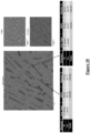
- FIG. 10 shows the results obtained by cutting the alloy produced in the Example and analyzing the residual impurity content in the inside of the alloy by energy dispersion spectrometry.
- the alloy is composed only of the desired metal Ti and Cu, and Mg used as the reducing metal does not exist at all.
Landscapes
- Chemical & Material Sciences (AREA)
- Engineering & Computer Science (AREA)
- Organic Chemistry (AREA)
- Metallurgy (AREA)
- Materials Engineering (AREA)
- Electrochemistry (AREA)
- Chemical Kinetics & Catalysis (AREA)
- Manufacturing & Machinery (AREA)
- Mechanical Engineering (AREA)
- Geology (AREA)
- General Life Sciences & Earth Sciences (AREA)
- Environmental & Geological Engineering (AREA)
- Life Sciences & Earth Sciences (AREA)
- Manufacture And Refinement Of Metals (AREA)
- Electrolytic Production Of Metals (AREA)
- Crucibles And Fluidized-Bed Furnaces (AREA)
Applications Claiming Priority (2)
| Application Number | Priority Date | Filing Date | Title |
|---|---|---|---|
| KR1020200154081A KR102386696B1 (ko) | 2020-11-17 | 2020-11-17 | 액상 금속 도가니를 이용한 고융점 금속 산화물의 환원 시스템 및 방법 |
| PCT/KR2021/003848 WO2022108006A1 (ko) | 2020-11-17 | 2021-03-29 | 액상 금속 도가니를 이용한 고융점 금속 산화물의 환원 시스템 및 방법 |
Publications (2)
| Publication Number | Publication Date |
|---|---|
| EP4249643A1 true EP4249643A1 (de) | 2023-09-27 |
| EP4249643A4 EP4249643A4 (de) | 2024-10-23 |
Family
ID=81212205
Family Applications (1)
| Application Number | Title | Priority Date | Filing Date |
|---|---|---|---|
| EP21894785.1A Pending EP4249643A4 (de) | 2020-11-17 | 2021-03-29 | Reduktionssystem und verfahren für hochschmelzende metalloxide mit flüssigmetalltiegel |
Country Status (8)
| Country | Link |
|---|---|
| US (1) | US20240026555A1 (de) |
| EP (1) | EP4249643A4 (de) |
| JP (1) | JP7580604B2 (de) |
| KR (1) | KR102386696B1 (de) |
| CN (1) | CN116583631A (de) |
| AU (1) | AU2021382943B2 (de) |
| CA (1) | CA3200992A1 (de) |
| WO (1) | WO2022108006A1 (de) |
Families Citing this family (1)
| Publication number | Priority date | Publication date | Assignee | Title |
|---|---|---|---|---|
| KR102638196B1 (ko) * | 2023-06-23 | 2024-02-16 | 충남대학교산학협력단 | Ⅳ족 전이금속 산화물로부터 저산소 전이금속 분말을 제조하기 위한 열환원 반응 혼합물과 이를 이용한 저산소 전이금속 분말 제조방법 |
Family Cites Families (22)
| Publication number | Priority date | Publication date | Assignee | Title |
|---|---|---|---|---|
| US4578242A (en) * | 1984-07-03 | 1986-03-25 | General Motors Corporation | Metallothermic reduction of rare earth oxides |
| US5035404A (en) | 1990-09-13 | 1991-07-30 | Westinghouse Electric Corp. | Retort assembly for kroll reductions |
| US5141723A (en) * | 1991-10-03 | 1992-08-25 | The United States Of America As Represented By The United States Department Of Energy | Uranium chloride extraction of transuranium elements from LWR fuel |
| US5769922A (en) * | 1996-04-12 | 1998-06-23 | Reading Alloys, Inc. | Method for producing vanadium-aluminum-ruthenium master alloys and master alloy compositions |
| BR9711581A (pt) * | 1996-09-30 | 2000-10-31 | Claude Fortin | Processo para a obtenção de titânio ou outros metais usando ligas lançadeira |
| ITTO970080A1 (it) * | 1997-02-04 | 1998-08-04 | Marco Vincenzo Ginatta | Procedimento per la produzione elettrolitica di metalli |
| JP2000239836A (ja) * | 1999-02-23 | 2000-09-05 | Japan Energy Corp | 高純度銅または銅合金スパッタリングターゲットおよびその製造方法 |
| AUPR443901A0 (en) * | 2001-04-10 | 2001-05-17 | Bhp Innovation Pty Ltd | Method for reduction of metal oxides to pure metals |
| WO2003046258A2 (en) * | 2001-11-22 | 2003-06-05 | Qit - Fer Et Titane Inc. | A method for electrowinning of titanium metal or alloy from titanium oxide containing compound in the liquid state |
| JP2004156130A (ja) * | 2002-09-11 | 2004-06-03 | Sumitomo Titanium Corp | 直接電解法による金属チタン製造用酸化チタン多孔質焼結体およびその製造方法 |
| JP4193984B2 (ja) * | 2003-08-28 | 2008-12-10 | 株式会社大阪チタニウムテクノロジーズ | 金属製造装置 |
| US7527669B2 (en) * | 2003-12-10 | 2009-05-05 | Babcock & Wilcox Technical Services Y-12, Llc | Displacement method and apparatus for reducing passivated metal powders and metal oxides |
| KR101070185B1 (ko) * | 2006-10-03 | 2011-10-05 | Jx닛코 닛세끼 킨조쿠 가부시키가이샤 | 구리-망간 합금 스퍼터링 타겟트 및 반도체 배선 |
| GB201106570D0 (en) * | 2011-04-19 | 2011-06-01 | Hamilton James A | Methods and apparatus for the production of metal |
| CN104919631B (zh) * | 2012-12-14 | 2019-08-02 | 尤米科尔公司 | 涂覆有内芯材料元素与一种或多种金属氧化物的混合物的锂金属氧化物颗粒 |
| JP6095374B2 (ja) * | 2013-01-11 | 2017-03-15 | 国立大学法人京都大学 | チタンの製造方法。 |
| KR101476308B1 (ko) * | 2013-04-30 | 2014-12-24 | 한국기계연구원 | 마그네슘을 이용한 금속산화물 환원장치 및 이를 이용한 금속산화물 환원방법 |
| KR101793471B1 (ko) * | 2016-07-20 | 2017-11-06 | 충남대학교산학협력단 | 전해환원 및 전해정련 공정에 의한 금속 정련 방법 |
| CA3047102C (en) * | 2016-09-14 | 2023-12-05 | Universal Achemetal Titanium, Llc | A method for producing titanium-aluminum-vanadium alloy |
| KR101878652B1 (ko) * | 2017-07-12 | 2018-07-16 | 충남대학교산학협력단 | 전해환원 및 전해정련 일관공정에 의한 금속 정련 방법 |
| CN207525356U (zh) * | 2017-09-22 | 2018-06-22 | 湖南金纯新材料有限公司 | 一种利用液态合金作为电极制备纯钛的装置 |
| KR102004920B1 (ko) * | 2019-01-28 | 2019-07-29 | 한국지질자원연구원 | 액체금속 음극을 이용한 금속 제련 방법 |
-
2020
- 2020-11-17 KR KR1020200154081A patent/KR102386696B1/ko active Active
-
2021
- 2021-03-29 JP JP2023529926A patent/JP7580604B2/ja active Active
- 2021-03-29 CA CA3200992A patent/CA3200992A1/en active Pending
- 2021-03-29 CN CN202180084249.3A patent/CN116583631A/zh active Pending
- 2021-03-29 AU AU2021382943A patent/AU2021382943B2/en active Active
- 2021-03-29 EP EP21894785.1A patent/EP4249643A4/de active Pending
- 2021-03-29 US US18/253,346 patent/US20240026555A1/en active Pending
- 2021-03-29 WO PCT/KR2021/003848 patent/WO2022108006A1/ko not_active Ceased
Also Published As
| Publication number | Publication date |
|---|---|
| AU2021382943A1 (en) | 2023-06-29 |
| AU2021382943A9 (en) | 2024-10-10 |
| EP4249643A4 (de) | 2024-10-23 |
| CA3200992A1 (en) | 2022-05-27 |
| AU2021382943B2 (en) | 2024-08-08 |
| JP2023549557A (ja) | 2023-11-27 |
| WO2022108006A1 (ko) | 2022-05-27 |
| JP7580604B2 (ja) | 2024-11-11 |
| CN116583631A (zh) | 2023-08-11 |
| KR102386696B1 (ko) | 2022-04-15 |
| US20240026555A1 (en) | 2024-01-25 |
Similar Documents
| Publication | Publication Date | Title |
|---|---|---|
| Fray | Emerging molten salt technologies for metals production | |
| EP0238185B1 (de) | Metallothermische Reduktion der Chloride der seltenen Erden | |
| AU758931B2 (en) | Removal of oxygen from metal oxides and solid solutions by electrolysis in a fused salt | |
| CN108138343B (zh) | 利用电解还原和电解精炼工序的金属精炼方法 | |
| JP5160554B2 (ja) | 高純度イッテルビウム、高純度イッテルビウムからなるスパッタリングターゲット、高純度イッテルビウムを含有する薄膜及び高純度イッテルビウムの製造方法 | |
| JP5445725B1 (ja) | Al−Sc合金の製造方法 | |
| KR101878652B1 (ko) | 전해환원 및 전해정련 일관공정에 의한 금속 정련 방법 | |
| US11591704B2 (en) | Electrolytic production of reactive metals | |
| EP4249643A1 (de) | Reduktionssystem und verfahren für hochschmelzende metalloxide mit flüssigmetalltiegel | |
| KR20140007011A (ko) | 고순도 에르븀, 고순도 에르븀으로 이루어지는 스퍼터링 타깃, 고순도 에르븀을 주성분으로 하는 메탈 게이트막 및 고순도 에르븀의 제조 방법 | |
| KR102765192B1 (ko) | 불화물계 전해질을 이용한 고융점 금속 산화물의 환원 방법 및 시스템 | |
| KR920007932B1 (ko) | 희토류-철 합금의 제조방법 | |
| KR101740424B1 (ko) | 일메나이트 원광을 이용한 금속 티타늄의 제조방법 | |
| EP4372108A1 (de) | Lithiumrückgewinnung aus schlacken | |
| CN102459665B (zh) | 分离铪和锆的工艺 | |
| WO2012143719A2 (en) | Methods and apparatus for the production of metal | |
| WO2006098199A1 (ja) | 高融点金属の分離回収方法 | |
| KR20230081581A (ko) | 금속 정련방법 및 금속 전해환원장치 | |
| JP2022168438A (ja) | マンガン回収方法 | |
| WO2023228537A1 (ja) | リチウム含有スラグ、並びに有価金属の製造方法 |
Legal Events
| Date | Code | Title | Description |
|---|---|---|---|
| STAA | Information on the status of an ep patent application or granted ep patent |
Free format text: STATUS: THE INTERNATIONAL PUBLICATION HAS BEEN MADE |
|
| PUAI | Public reference made under article 153(3) epc to a published international application that has entered the european phase |
Free format text: ORIGINAL CODE: 0009012 |
|
| STAA | Information on the status of an ep patent application or granted ep patent |
Free format text: STATUS: REQUEST FOR EXAMINATION WAS MADE |
|
| 17P | Request for examination filed |
Effective date: 20230601 |
|
| AK | Designated contracting states |
Kind code of ref document: A1 Designated state(s): AL AT BE BG CH CY CZ DE DK EE ES FI FR GB GR HR HU IE IS IT LI LT LU LV MC MK MT NL NO PL PT RO RS SE SI SK SM TR |
|
| DAV | Request for validation of the european patent (deleted) | ||
| DAX | Request for extension of the european patent (deleted) | ||
| A4 | Supplementary search report drawn up and despatched |
Effective date: 20240920 |
|
| RIC1 | Information provided on ipc code assigned before grant |
Ipc: C22B 34/12 20060101ALI20240916BHEP Ipc: C22B 9/10 20060101ALI20240916BHEP Ipc: C22B 9/05 20060101ALI20240916BHEP Ipc: C22B 9/04 20060101ALI20240916BHEP Ipc: C25C 3/34 20060101ALI20240916BHEP Ipc: C25C 3/30 20060101ALI20240916BHEP Ipc: C25C 3/28 20060101ALI20240916BHEP Ipc: C25C 3/26 20060101ALI20240916BHEP Ipc: C22B 9/14 20060101ALI20240916BHEP Ipc: C22B 5/04 20060101ALI20240916BHEP Ipc: C25C 3/36 20060101ALI20240916BHEP Ipc: C25C 7/06 20060101ALI20240916BHEP Ipc: C25C 7/00 20060101AFI20240916BHEP |