EP4249687A2 - Dispositif de préhension et procédé de fonctionnement d'un dispositif de préhension - Google Patents
Dispositif de préhension et procédé de fonctionnement d'un dispositif de préhension Download PDFInfo
- Publication number
- EP4249687A2 EP4249687A2 EP23186291.3A EP23186291A EP4249687A2 EP 4249687 A2 EP4249687 A2 EP 4249687A2 EP 23186291 A EP23186291 A EP 23186291A EP 4249687 A2 EP4249687 A2 EP 4249687A2
- Authority
- EP
- European Patent Office
- Prior art keywords
- gripper
- cable
- blades
- rope
- actuating
- Prior art date
- Legal status (The legal status is an assumption and is not a legal conclusion. Google has not performed a legal analysis and makes no representation as to the accuracy of the status listed.)
- Pending
Links
Images

Classifications
-
- E—FIXED CONSTRUCTIONS
- E02—HYDRAULIC ENGINEERING; FOUNDATIONS; SOIL SHIFTING
- E02F—DREDGING; SOIL-SHIFTING
- E02F3/00—Dredgers; Soil-shifting machines
- E02F3/04—Dredgers; Soil-shifting machines mechanically-driven
- E02F3/46—Dredgers; Soil-shifting machines mechanically-driven with reciprocating digging or scraping elements moved by cables or hoisting ropes ; Drives or control devices therefor
- E02F3/47—Dredgers; Soil-shifting machines mechanically-driven with reciprocating digging or scraping elements moved by cables or hoisting ropes ; Drives or control devices therefor with grab buckets
-
- E—FIXED CONSTRUCTIONS
- E02—HYDRAULIC ENGINEERING; FOUNDATIONS; SOIL SHIFTING
- E02D—FOUNDATIONS; EXCAVATIONS; EMBANKMENTS; UNDERGROUND OR UNDERWATER STRUCTURES
- E02D17/00—Excavations; Bordering of excavations; Making embankments
- E02D17/13—Foundation slots or slits; Implements for making these slots or slits
-
- E—FIXED CONSTRUCTIONS
- E02—HYDRAULIC ENGINEERING; FOUNDATIONS; SOIL SHIFTING
- E02F—DREDGING; SOIL-SHIFTING
- E02F3/00—Dredgers; Soil-shifting machines
- E02F3/04—Dredgers; Soil-shifting machines mechanically-driven
- E02F3/28—Dredgers; Soil-shifting machines mechanically-driven with digging tools mounted on a dipper- or bucket-arm, i.e. there is either one arm or a pair of arms, e.g. dippers, buckets
- E02F3/36—Component parts
- E02F3/42—Drives for dippers, buckets, dipper-arms or bucket-arms
- E02F3/43—Control of dipper or bucket position; Control of sequence of drive operations
-
- E—FIXED CONSTRUCTIONS
- E02—HYDRAULIC ENGINEERING; FOUNDATIONS; SOIL SHIFTING
- E02F—DREDGING; SOIL-SHIFTING
- E02F3/00—Dredgers; Soil-shifting machines
- E02F3/04—Dredgers; Soil-shifting machines mechanically-driven
- E02F3/46—Dredgers; Soil-shifting machines mechanically-driven with reciprocating digging or scraping elements moved by cables or hoisting ropes ; Drives or control devices therefor
- E02F3/58—Component parts
- E02F3/60—Buckets, scrapers, or other digging elements
Definitions
- the invention relates to a method for operating a gripper device with a carrier device and a cable gripper arranged thereon, which has a gripper frame which is held on the carrier device via a tether, at least two gripper blades which can be pivoted at a lower end of the gripper frame between a closed position and an open position are mounted, and has an actuating device with an actuating cable for pivoting the gripper blades, an actuating cable being guided from the carrier device to the actuating device and the carrier device having a driven first cable winch for the tether and a driven second cable winch for the actuating cable, the carrier device having a Undercarriage and an uppercarriage rotatably mounted thereon about a vertical axis with an outrigger arm on which the cable gripper is mounted in a vertically adjustable manner, the cable gripper with open gripper blades being lowered into the ground by means of the retaining cable in a removal step to form a slot in the ground for removal and picking up soil material, the
- the invention further relates to a gripper device with a carrier device and a cable gripper arranged thereon, which has a gripper frame which is held on the carrier device via a tether, at least two gripper blades which are pivotably mounted at a lower end of the gripper frame between a closed position and an open position, and an actuating device with an actuating cable for pivoting the gripper blades, an actuating cable being guided from the carrier device to the actuating device and the carrier device having a driven first cable winch for the tether and a driven second cable winch for the actuating cable, the carrier device having an undercarriage and an has a superstructure mounted thereon that can be rotated about a vertical axis and has an outrigger arm on which the cable gripper is suspended in a vertically adjustable manner, according to the preamble of claim 9.
- Gripper devices essentially include a gripper with gripper blades, the gripper being suspended from a carrier device, typically a jib crane, via a tether.
- a grab can be lowered into the ground using the tether.
- soil material can be removed and picked up in the grab.
- the gripper is then pulled back out of the ground via the retaining cable and/or operating cable and pivoted with the carrier device to an emptying position, at which the gripper blades are opened to release the soil material.
- the gripper is then pivoted back into the working position and inserted into the slot in the floor for another gripping process.
- a so-called hydraulic gripper is, for example, from the EP 3 798 367 A1 known.
- a hydraulic gripper the movement for opening and closing the gripper blades is generated by a hydraulic cylinder which is arranged on the gripper frame.
- Such hydraulic grippers can be operated and controlled relatively easily by the hydraulic system.
- appropriate hydraulic lines are required to supply and remove hydraulic fluid, which run parallel to the tether.
- Appropriate line reels for the hydraulic lines with appropriate winch drives as well as an appropriately designed hydraulic system must be provided on the carrier device.
- the gripper device is correspondingly enlarged and also more expensive.
- the hydraulic system also requires additional maintenance.
- rope grippers offer a significantly simplified structure.
- a rope gripper is, for example, from GB 2 126 981 A known.
- the actuation cable runs essentially parallel to the tether from the actuation device of the gripper blades to the carrier device.
- the gripper blades can be opened or closed by unwinding or winding the operating cable onto the winches.
- a machine operator can bring about a rotational position of the cable gripper about its longitudinal axis by applying certain tensile forces to the retaining cable and the operating cable. This requires relatively sensitive operation of the corresponding cable winches. This requires the machine operator to have a certain amount of experience and also a high level of concentration when carrying out the process. In addition, cable winches are often operated using foot pedals, so that sensitive operation of the cable winches over several hours is also very strenuous for a machine operator.
- the invention is based on the object of specifying a method for operating the gripper device and a gripper device in which a simple structure of the gripper device is provided and at the same time simple operation is made possible.
- the method according to the invention is characterized in that a control device is provided with which rotation of the superstructure to the emptying position and opening of the gripper blades to dispense the soil material and/or rotation of the superstructure from the emptying position back to the soil slot are controlled automatically.
- the gripper device can be rotated about its vertical axis.
- a basic idea of the invention is to provide a control device through which, on the one hand, a rotary drive for the superstructure and, on the other hand, at least one cable winch for the operating cable are controlled in a coordinated manner. This makes it possible to move the rope gripper quickly and efficiently and empty it at the emptying position.
- a complex manual control by a machine operator and the coordination of the control of the rotation of the superstructure and / or the gripper device with the actuation of the cable winch for the operating cable and the cable winch for the tether with the usually existing foot pedals can be omitted. This represents a significant relief Machine operator both in physical and coordination terms, especially since a simply constructed rope gripper tends to oscillate, i.e. swing and/or twist.
- the invention allows a rope gripper to be operated safely and efficiently even by a less experienced machine operator.
- the superstructure can be rotated from the emptying position back to the bottom slot.
- the control device can therefore be used to carry out the repetitive movement of the rope gripper from the working position at the bottom slot to the emptying position and back completely, almost completely or at least partially automatically.
- a first process can initially be carried out manually by a machine operator, while a corresponding automatic program is created by the control device in a teach-in process. After the automatic program has been saved, it can be executed repeatedly, thereby significantly reducing the workload for the machine operator.
- particularly efficient emptying is achieved in that the control device opens the gripper blades while the cable gripper is in a pendulum movement due to the rotation of the superstructure.
- a dynamic emptying process can be achieved in this way, in which the rope gripper does not have to swing over the emptying point. This means a significant acceleration of the work process.
- the pendulum movement of the rope grab can be caused not only by the twisting of the superstructure, but also by the operation of the rope winches.
- the pendulum movement can include not only swinging in an approximately horizontal direction but also rotating or torsional swinging in an approximately vertical direction.
- the control device can control both the cable winch for the operating cable and the cable winch for the retaining cable in such a way that a pendulum movement of the cable gripper suspended from the cable is counteracted. This promotes occupational safety.
- control device automatically controls a movement of the rope gripper into the bottom slot and/or a retraction of the rope gripper from the bottom slot.
- the retraction and extension of the diaphragm wall grab can also be carried out automatically become.
- the increasing depth of the slot can also be taken into account.
- the machine operator preferably has the option at any time to carry out these process steps or other process steps by directly intervening in the control device. This can be done under direct control by the machine operator, particularly when the diaphragm wall grab is inserted into a slot in the ground.
- control device can carry out a program step which leads to a calming of the movement of the rope gripper around a vertical axis (twisting) as well as transversely to the vertical axis (swinging) immediately before entry into the created slot.
- control device is connected to the first cable winch and the second cable winch and controls them. In this way, coordinated operation of the holding and operating cable can be carried out in order to limit or avoid unwanted rotational and pendulum movements of the cable gripper.
- a particularly expedient operation of the gripper device results from the fact that a sensor device is provided with which a pendulum movement of the cable gripper is detected when the superstructure is rotated.
- the sensor device can be camera-based or have other contact or non-contact sensors with which a pendulum movement transverse to the vertical and/or a twisting pendulum movement about a vertical axis can be detected.
- the movement data recorded in this way can be used by the control device in particular to control one or both cable winches in order to counteract the undesirable or excessive pendulum movement.
- control device opens the gripper blades at the emptying position at a time at which the oscillating cable gripper is still in a deflected position in the vertical position. Overall, this leads to an acceleration of the entire process.
- the pendulum movement can be counteracted by the targeted emptying of the rope gripper in a deflected position, as the resulting reduction in the oscillating mass has a calming effect on the pendulum movement.
- a further efficient process sequence can also be achieved in that the oscillating rope gripper is retracted into the floor slot by the control device, the pendulum movement being calmed by contact with the floor. After a certain reduction in the pendulum movement has been achieved, the pendulum movement can be completely calmed by specifically retracting the rope gripper into the floor slot.
- the invention is characterized in that a control device is provided which is designed to automatically rotate the superstructure to an emptying position and open the gripper blades to dispense soil material and/or rotate the superstructure from the emptying position back to the soil slot to control.
- the gripper device according to the invention is particularly preferred for the gripper device according to the invention to be designed to carry out the previously described method according to the invention.
- a first detection device for detecting a first cable force on the tether and a second detection device for detecting a second cable force on the actuating cable are provided, and that the control device is connected to the first detection device second detection device of the first cable winch and the second cable winch is connected and is designed to control the first cable winch and / or the second cable winch according to a control program specification depending on the detected first cable force on the tether and the detected second cable force on the actuating cable.
- One aspect of the invention is based on the knowledge that a torque on a cable gripper about its longitudinal axis depends on the cable forces in the tether and the operating cable.
- Detection devices are provided with which a cable force on the retaining cable and a cable force on the operating cable are detected.
- the force values recorded in each case can be fed to a control device, which has a first cable winch for the holding cable and a second cable winch for the operating cable in accordance with inputs and specifications from the machine operator controls.
- the forces in the retaining cable and in the operating cable can be coordinated with one another via a corresponding control of the respective cable winch (winding/unwinding), so that in particular no torque about the longitudinal axis is caused by the cable gripper at a given or desired rotational position Retaining rope and the operating rope are generated.
- the control device can also be used to generate a defined variable torque for a desired rotation by appropriately influencing the respective cable forces. This can counteract a pendulum movement.
- a preferred embodiment of the invention is that a defined relationship between the first cable force in the tether and the second cable force in the actuating cable is predetermined and adjustable by the control program specification of the control device.
- the same or different designs of the tether and actuation cable can be taken into account.
- torque compensation can be achieved by setting largely equal tensile forces in the cables.
- the ropes are designed differently with regard to a different rope structure, this can be taken into account and preset in the control program specification.
- additional geometric conditions on the rope grab can also be preset and taken into account, for example with regard to different attachment points of the ropes on the grab frame.
- a further preferred embodiment of the invention is that the control device is designed with a compensation mode in which the cable winches are controlled in such a way that the first cable force on the tether and the second cable force on the operating cable are equalized to one another.
- the cable winches can be controlled in such a way that the torques in the actuation cable and the retaining cable compensate for or weaken each other. This allows the rotational position of the rope gripper to be stabilized about its longitudinal axis. Undesirable rotation of the rope gripper about its longitudinal axis during operation can thus largely be avoided.
- the control device is designed with a twisting mode in which the cable winches are controlled in such a way that a targeted rotation of the cable gripper about a vertical longitudinal axis can be generated.
- a machine operator can effect a desired change in the rotational position.
- the control device can also be designed in such a way that a value or a measure for a desired rotation is specified by the machine operator via an input device, the winches being actuated by the control device in accordance with the program logic in such a way that the desired changed rotational position is achieved.
- a further preferred embodiment of the invention is that the control device is designed with a mode for opening and/or closing the gripper blades at a predetermined height. This means that when opening and/or closing the two cable winches can be coordinated with one another in such a way that the lowest point of the gripper blades preferably remains at the same height or a certain height change is achieved.
- closing for example, it can be controlled whether the teeth or tooth tips of the gripper blades move on a circular path or a straight path or a defined path in between. This can be adjustable in particular depending on the type of soil.
- the gripper can be held freely hanging with closed gripper blades on the operating cable and retaining cable, with the cable force in the operating cable and retaining cable being approximately the same, for example corresponding to approximately +/- 1 t.
- the winch on which the operating cable is wound is automatically actuated in the direction of unwinding, which occurs either in free fall or force-fitting.
- the winch on which the tether is wound is automatically operated in the direction of winding up. This causes a carriage in the gripper body to move upwards and open the gripper blades via the push rods.
- control device can be designed with a mode for closing the gripper blades.
- the two cable winches can be coordinated with one another in such a way that the lowest point of the gripper blades preferably remains at the same height. Accordingly, when closing, it can be controlled whether the teeth or tooth tips of the gripper blades move on a circular path or a straight path or a curve in between, which can be adjusted in particular depending on the type of soil.
- the gripper can be held freely hanging with the gripper blade open on the operating cable and retaining cable, whereby the cable force in the retaining cable corresponds almost to the entire gripper weight and the cable force in the operating cable is in the range of approximately 1 t to 2 t.
- the winch on which the operating rope is wound is automatically actuated in the direction of winding up and at the same time the winch on which the tether rope is wound is automatically actuated in the direction of unwinding either in free fall or non-positively. This causes the carriage to move downwards in the gripper body and close the gripper blade via the push rods.
- a further preferred embodiment of the invention further consists in that the control device is designed with a mode for automatically opening and immediately closing the gripper blades.
- the gripper can be held freely hanging with a closed, filled gripper blade on the operating cable and retaining cable, with the cable force in the operating cable and retaining cable being approximately the same, in particular corresponding to approximately +/- 1 t.
- the processes of opening and closing the gripper blades are carried out automatically in one process.
- the aim is to do this in the shortest possible period of time to be carried out because for the “grab bucket open” state the rope force in the retaining rope is significantly higher than in the operating rope. This can lead to the gripper twisting around the longitudinal axis.
- an angular impulse in the opposite direction can occur before the automatic opening/closing function is carried out, in particular through an automatic, targeted short-term increase in the cable force in the operating cable.
- control device can detect the degree of opening of the gripper blades and this is visualized for the operator.
- the degree of opening of the gripper blade By recording the ratio of the depth or unwinding length of the retaining cable and the operating cable, it is possible to determine the degree of opening of the gripper blade via the device control and, in particular, to visualize it for an operator on a screen. This can be done by displaying a numerical value, such as an opening degree of 50%, and/or a graphical representation, such as displaying the gripper blades with an opening angle or as a bar graph. Without this display, the degree of opening of the blades and thus the status of the gripper in the slot is not visually visible to the operator.
- At least a third detection device is provided for detecting a rotational position of the rope gripper and/or a change in the rotational position.
- This can be done using an optical detection device, rotary encoder, a gyroscope on the rope gripper or in another suitable manner. Feedback on the rotational position or rotation of the gripper can thus take place when activated by the control device, so that the rotational position or rotation can be regulated. This enables a particularly precise adjustment of the rotational position of the rope gripper.
- a further improvement in operability results from a further embodiment of the invention in that at least one further detection device is provided, in particular for detecting a vertical position of the rope gripper, a distance and/or an angular position of the rope gripper to the carrier device.
- the additional parameters recorded in this way can be provided to a machine operator be displayed immediately and/or processed by the control device for controlling the gripper.
- a further advantageous embodiment of the invention is that a control panel is provided for a manual control for actuating the cable gripper and/or the cable winches.
- the control panel as an input device is designed in particular in such a way that a desired rotation or movement of the rope gripper, for example as a numerical value or angle measure, is entered by a machine operator, preferably using appropriate controls, such as a cursor, a rotary wheel, switches or buttons, in particular in combination with a display.
- the machine operator therefore no longer has to directly enter the winches and the rotation of the winches. Rather, in accordance with the operating input regarding the position of the gripper, the machine with the individual motors and actuators is controlled via the control device with the program logic in such a way that the desired position is achieved largely without undesirable rotations.
- control device is designed with an automatic program through which the rope gripper can be automatically moved to an emptying position and/or to a removal point.
- An automatic program can be permanently stored or can be individually defined and saved by a machine operator for repetitive processes. In this way, larger movements of the gripper can be carried out automatically, in particular a movement to the emptying position and/or back to a removal point. Such travel paths of the rope gripper occur particularly when creating deep slots in the ground with a high repetition frequency.
- the individual ropes can be designed the same or different.
- the retaining cable on the first cable winch has a first winding which is opposite to a second winding of the operating cable on the second cable winch.
- the tether and the actuating cable have a direction of lay that is opposite to one another or a so-called rope lay. When a tensile force is applied, opposite torques arise on the ropes. This makes it easier to compensate for the torques to stabilize the position of the rope gripper during operation.
- a display screen is provided for the control device for operation.
- the display screen can in particular be designed as a touchscreen on which at least some of the control elements for a machine operator are implemented.
- a position of the rope gripper can be displayed in various representations on the display screen in order to further make operation easier for a machine operator.
- the gripper device can be used in particular for different tasks.
- a preferred method variant is that soil is removed using the rope grab and in particular a slot is created in the soil.
- the rope grab can in particular be designed as a so-called diaphragm wall grab, with which a slot can be created for a sealing and/or supporting wall in the ground, for example for an excavation pit enclosure.
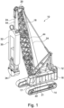
- a gripper device 10 according to the invention Fig. 1 has a mobile carrier device 12 with a crawler chassis as an undercarriage 14.
- An uppercarriage 16 with an operating cabin 17 is mounted on the undercarriage 14 so that it can rotate about a vertical axis of rotation.
- An outrigger arm 18 is pivotally connected to the superstructure 16 about a horizontal axis.
- a tether 24 is guided on a head 20 of the boom arm 18 with deflection rollers, at the end of which a rope gripper 30 with a gripper frame 32 and lower gripper blades 34 is attached.
- the tether 24 can be operated to raise and lower the cable gripper 30 via a first cable winch 21 on the carrier device 12.
- a second cable winch 22 on the carrier device 12 for an operating cable 44, which is also guided over the head 20 to the cable gripper 30 for actuating the gripper blades 34 at the lower end of the gripper frame 32.
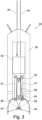
- an actuating carriage 42 of an actuating device 40 for actuating the gripper blades 34 is mounted so that it can be displaced in a vertical longitudinal direction.
- the end of the retaining rope 24 is attached, so that the rope gripper 30 is held over the operating carriage 42.
- an articulation mechanism 46 with articulation rods 47 is arranged at a lower end of the actuating carriage 42.
- the link rods 47 are articulated on the one hand to the actuating carriage 42 and on the other hand to one of the gripper blades 34.
- the gripper blades 34 are themselves pivotably mounted at the lower end of the gripper frame 32 via pivot bearings 35.
- the gripper blades 34 can be opened and closed by a relative displacement of the actuating carriage 42 with respect to the gripper frame 32.
- the linkage rods 47 are pulled upwards, with the gripper blade 34 being pivoted about their pivot axes 35 into their opening position, which is clearly shown in Fig. 3 is shown.
- the pulley arrangement 50 has at least one upper roller 52, which is rotatably mounted on the operating carriage 42, and at least one lower roller 54, which is rotatably mounted on a lower region of the gripper frame 32.
- the rollers 52, 54 are controlled by the operating cable 44 supplied from above, forming loops 56 or trains wrapped around, the lower end of the operating cable 44 being firmly connected to the gripper frame 32.
- the actuating carriage 42 is thus adjustably connected or coupled to the gripper frame 32 via the actuating cable 44.
- soil material When used in a slot in the ground, soil material can be gripped and enclosed between the gripper blades 34 with a closing force that is higher than the tensile force on the operating cable 44.
- the superstructure 16 When the gripper blades 34 are filled, the superstructure 16 is removed from the in Fig. 1 position shown is automatically pivoted by 90 degrees around the vertical axis to an emptying position.
- the boom arm 18 can also be adjusted.
- the gripper blades 34 are opened to release the soil material, even if the cable gripper 30 is still performing a pendulum movement.
- the rope gripper 30 can also be rotated about its longitudinal axis in order to align it with the trough of a truck.
- the superstructure 16 can then automatically return to the position according to Fig. 1 be swung back.
- the rope grab 30 is lowered into the ground into a slot in order to pick up new soil material when the grab blades 34 are open.
- the gripper blades 34 are then pulled back to the position Fig. 1 and another emptying process.
- forces in the retaining cable 24 and the operating cable 44 are recorded via appropriate detection devices, which can be arranged, for example, on the cable winches 21, 22 or on the deflection rollers on the head 20 of the boom arm 18.
- appropriate detection devices which can be arranged, for example, on the cable winches 21, 22 or on the deflection rollers on the head 20 of the boom arm 18.
- the winches 21, 22 can be controlled depending on the detected rope forces in such a way that either a stabilization of the pendulum movement to the longitudinal axis or the rotational position of the rope gripper 30 about its longitudinal axis or a Targeted rotation desired by the machine operator is achieved.
- the machine operator can make appropriate entries into the control device for a desired automatic movement, a compensation mode for position stabilization or entries for a desired rotational position of the steep gripper 30.
- control device of the superstructure 16 can correspondingly control the boom arm 18 or the cable winches 21, 22 in order to effect the desired positioning and opening/closing of the cable gripper 30. This considerably simplifies and facilitates the control of a simply constructed rope gripper 30 for a machine operator.
Landscapes
- Engineering & Computer Science (AREA)
- Mining & Mineral Resources (AREA)
- Mechanical Engineering (AREA)
- Civil Engineering (AREA)
- General Engineering & Computer Science (AREA)
- Structural Engineering (AREA)
- Life Sciences & Earth Sciences (AREA)
- General Life Sciences & Earth Sciences (AREA)
- Paleontology (AREA)
- Earth Drilling (AREA)
- Control And Safety Of Cranes (AREA)
- Load-Engaging Elements For Cranes (AREA)
Priority Applications (1)
| Application Number | Priority Date | Filing Date | Title |
|---|---|---|---|
| EP23186291.3A EP4249687A3 (fr) | 2021-08-12 | 2021-08-12 | Dispositif de préhension et procédé de fonctionnement d'un dispositif de préhension |
Applications Claiming Priority (2)
| Application Number | Priority Date | Filing Date | Title |
|---|---|---|---|
| EP21191054.2A EP4134490B1 (fr) | 2021-08-12 | 2021-08-12 | Dispositif préhenseur et procédé de fonctionnement d'un dispositif préhenseur |
| EP23186291.3A EP4249687A3 (fr) | 2021-08-12 | 2021-08-12 | Dispositif de préhension et procédé de fonctionnement d'un dispositif de préhension |
Related Parent Applications (2)
| Application Number | Title | Priority Date | Filing Date |
|---|---|---|---|
| EP21191054.2A Division EP4134490B1 (fr) | 2021-08-12 | 2021-08-12 | Dispositif préhenseur et procédé de fonctionnement d'un dispositif préhenseur |
| EP21191054.2A Division-Into EP4134490B1 (fr) | 2021-08-12 | 2021-08-12 | Dispositif préhenseur et procédé de fonctionnement d'un dispositif préhenseur |
Publications (2)
| Publication Number | Publication Date |
|---|---|
| EP4249687A2 true EP4249687A2 (fr) | 2023-09-27 |
| EP4249687A3 EP4249687A3 (fr) | 2023-11-29 |
Family
ID=77316903
Family Applications (2)
| Application Number | Title | Priority Date | Filing Date |
|---|---|---|---|
| EP21191054.2A Active EP4134490B1 (fr) | 2021-08-12 | 2021-08-12 | Dispositif préhenseur et procédé de fonctionnement d'un dispositif préhenseur |
| EP23186291.3A Pending EP4249687A3 (fr) | 2021-08-12 | 2021-08-12 | Dispositif de préhension et procédé de fonctionnement d'un dispositif de préhension |
Family Applications Before (1)
| Application Number | Title | Priority Date | Filing Date |
|---|---|---|---|
| EP21191054.2A Active EP4134490B1 (fr) | 2021-08-12 | 2021-08-12 | Dispositif préhenseur et procédé de fonctionnement d'un dispositif préhenseur |
Country Status (6)
| Country | Link |
|---|---|
| US (1) | US20250137225A1 (fr) |
| EP (2) | EP4134490B1 (fr) |
| JP (1) | JP7769780B2 (fr) |
| CN (1) | CN117897533A (fr) |
| ES (1) | ES3019934T3 (fr) |
| WO (1) | WO2023016883A1 (fr) |
Cited By (1)
| Publication number | Priority date | Publication date | Assignee | Title |
|---|---|---|---|---|
| WO2025113766A1 (fr) * | 2023-11-27 | 2025-06-05 | Bauer Maschinen Gmbh | Dispositif de préhension et procédé de fonctionnement d'un dispositif de préhension |
Families Citing this family (4)
| Publication number | Priority date | Publication date | Assignee | Title |
|---|---|---|---|---|
| DE102022123785A1 (de) * | 2022-09-16 | 2024-03-21 | Liebherr-Werk Nenzing Gmbh | Arbeitsgerät mit einem mechanischen Schlitzwandgreifer und Verfahren zum Durchführen eines Arbeitsschritts eines solchen |
| EP4675050A1 (fr) | 2024-07-01 | 2026-01-07 | BAUER Maschinen GmbH | Pince à câble et procédé de fonctionnement d'une pince à câble |
| EP4675048A1 (fr) | 2024-07-01 | 2026-01-07 | BAUER Maschinen GmbH | Pince à câble et procédé de fonctionnement d'une pince à câble |
| DE102024125138A1 (de) * | 2024-09-03 | 2026-03-05 | Liebherr-Werk Nenzing Gmbh | Arbeitsgerät mit einem Greifer, insbesondere Schlitzwandgreifer |
Citations (2)
| Publication number | Priority date | Publication date | Assignee | Title |
|---|---|---|---|---|
| GB2126981A (en) | 1982-09-13 | 1984-04-04 | Frankignoul Pieux Armes | Improvements in or relating to grab bucket apparatus |
| EP3798367A1 (fr) | 2019-09-25 | 2021-03-31 | BAUER Maschinen GmbH | Élément d'ancrage sur une tranchée, son procédé de fonctionnement et procédé de construction souterraine |
Family Cites Families (16)
| Publication number | Priority date | Publication date | Assignee | Title |
|---|---|---|---|---|
| US3479077A (en) * | 1968-09-24 | 1969-11-18 | Robert W Martin | Hydraulically actuated bucket closing means |
| JPS4895007A (fr) * | 1972-03-21 | 1973-12-06 | ||
| DE3615068C1 (en) * | 1986-05-03 | 1987-10-08 | Dyckerhoff & Widmann Ag | Rope-guided trench-wall grab |
| JPH07119473B2 (ja) * | 1990-02-19 | 1995-12-20 | 株式会社フジタ | 地中連続壁用溝の自動掘削装置 |
| FR2681352B1 (fr) * | 1991-09-16 | 1998-07-24 | Sol Cie | Appareil d'excavation a benne preneuse. |
| JP3062410B2 (ja) * | 1994-11-22 | 2000-07-10 | 日本鋼管株式会社 | 光ファイバージャイロ付きクレーン用フック |
| JP2000255973A (ja) * | 1999-03-04 | 2000-09-19 | Kobelco Contstruction Machinery Ltd | バケット作業機械の運転制御装置 |
| JP4318807B2 (ja) * | 1999-08-25 | 2009-08-26 | 株式会社鴻池組 | 掘削揚土作業支援システム |
| JP3941428B2 (ja) * | 2001-07-27 | 2007-07-04 | 株式会社大林組 | バケット式掘削機およびその運転方法 |
| JP3866962B2 (ja) * | 2001-11-12 | 2007-01-10 | コベルコ建機株式会社 | 深穴作業機 |
| JP2004293069A (ja) * | 2003-03-26 | 2004-10-21 | Minotsu Tekko Kk | 掘削バケット |
| DE20310240U1 (de) * | 2003-07-03 | 2003-09-11 | Wolfgang Rohr GmbH & Co. KG, 67165 Waldsee | Motorgreifer, insbesondere Motorunterwassergreifer |
| CL2012000933A1 (es) * | 2011-04-14 | 2014-07-25 | Harnischfeger Tech Inc | Un metodo y una pala de cable para la generacion de un trayecto ideal, comprende: un motor de oscilacion, un motor de izaje, un motor de avance, un cucharon para excavar y vaciar materiales y, posicionar la pala por medio de la operacion del motor de izaje, el motor de avance y el motor de oscilacion y; un controlador que incluye un modulo generador de un trayecto ideal. |
| KR101354146B1 (ko) * | 2012-03-02 | 2014-01-27 | 주식회사 준엔지니어링 | 오토센터링기능을 가지는 토사굴착용 그라브장치 |
| JP5746409B1 (ja) * | 2014-10-08 | 2015-07-08 | 久保建株式会社 | バケットの旋回姿勢調整装置、およびバケットの旋回姿勢調整方法 |
| WO2019163875A1 (fr) * | 2018-02-22 | 2019-08-29 | 株式会社タダノ | Dispositif de caméra, système de surveillance de charge suspendue et machine de travail |
-
2021
- 2021-08-12 EP EP21191054.2A patent/EP4134490B1/fr active Active
- 2021-08-12 EP EP23186291.3A patent/EP4249687A3/fr active Pending
- 2021-08-12 ES ES21191054T patent/ES3019934T3/es active Active
-
2022
- 2022-08-03 US US18/682,958 patent/US20250137225A1/en active Pending
- 2022-08-03 JP JP2024508712A patent/JP7769780B2/ja active Active
- 2022-08-03 CN CN202280055530.9A patent/CN117897533A/zh active Pending
- 2022-08-03 WO PCT/EP2022/071804 patent/WO2023016883A1/fr not_active Ceased
Patent Citations (2)
| Publication number | Priority date | Publication date | Assignee | Title |
|---|---|---|---|---|
| GB2126981A (en) | 1982-09-13 | 1984-04-04 | Frankignoul Pieux Armes | Improvements in or relating to grab bucket apparatus |
| EP3798367A1 (fr) | 2019-09-25 | 2021-03-31 | BAUER Maschinen GmbH | Élément d'ancrage sur une tranchée, son procédé de fonctionnement et procédé de construction souterraine |
Cited By (1)
| Publication number | Priority date | Publication date | Assignee | Title |
|---|---|---|---|---|
| WO2025113766A1 (fr) * | 2023-11-27 | 2025-06-05 | Bauer Maschinen Gmbh | Dispositif de préhension et procédé de fonctionnement d'un dispositif de préhension |
Also Published As
| Publication number | Publication date |
|---|---|
| JP2024530219A (ja) | 2024-08-16 |
| WO2023016883A1 (fr) | 2023-02-16 |
| EP4134490B1 (fr) | 2025-02-12 |
| EP4134490A1 (fr) | 2023-02-15 |
| EP4249687A3 (fr) | 2023-11-29 |
| US20250137225A1 (en) | 2025-05-01 |
| CN117897533A (zh) | 2024-04-16 |
| ES3019934T3 (en) | 2025-05-21 |
| EP4134490C0 (fr) | 2025-02-12 |
| JP7769780B2 (ja) | 2025-11-13 |
Similar Documents
| Publication | Publication Date | Title |
|---|---|---|
| EP4134490B1 (fr) | Dispositif préhenseur et procédé de fonctionnement d'un dispositif préhenseur | |
| EP4134489B1 (fr) | Dispositif préhenseur et procédé de fonctionnement d'un dispositif préhenseur | |
| EP1950353B1 (fr) | Dispositif d'excavation du sol | |
| DE2430319A1 (de) | Hebevorrichtung, insbesondere hydraulischer kran | |
| DE3339495A1 (de) | Verfahren und vorrichtung zum horizontalen vergiessen von beton | |
| DE102015115146A1 (de) | Baumaschine und Verfahren zum Auf- und Abbewegen eines Hubelementes | |
| EP3725951B1 (fr) | Dispositif de benne et procédé de fabrication d'une fouille de fondation | |
| EP3425123A1 (fr) | Console d'un engin | |
| DE3018560C2 (fr) | ||
| DE102022123785A1 (de) | Arbeitsgerät mit einem mechanischen Schlitzwandgreifer und Verfahren zum Durchführen eines Arbeitsschritts eines solchen | |
| EP4149876A1 (fr) | Dispositif de préhension doté d'un système de commande de fermeture par multiplication de force démultipliée | |
| DE1634733C3 (de) | Hochlöffelbagger | |
| DE2212876A1 (de) | Teleskopstange fuer Maschine fuer Gruendungsarbeiten | |
| DE828439C (de) | Am Ausleger eines Kranes aufgehaengter Greifer | |
| EP4105389A1 (fr) | Procédé de fonctionnement d'une machine de construction et machine de construction | |
| WO2025098585A1 (fr) | Appareil de préhension et procédé de fonctionnement d'un appareil de préhension | |
| WO2024074366A1 (fr) | Engin de génie civil et procédé de fonctionnement d'un engin de génie civil | |
| WO2025113766A1 (fr) | Dispositif de préhension et procédé de fonctionnement d'un dispositif de préhension | |
| EP4215717B1 (fr) | Machine de construction et procédé de fonctionnement d'une machine de construction | |
| DE2929463C2 (de) | Hydraulisch betätigter Bagger | |
| WO2012045444A1 (fr) | Machine de travail à fonction de burinage | |
| DE2542161A1 (de) | Loeffelbagger | |
| EP0702111A2 (fr) | Racleur radial | |
| CH687999A5 (de) | Tagebauloeffelbagger. | |
| DE102012006306A1 (de) | Reinigungsvorrichtung für eine Bohrschnecke |
Legal Events
| Date | Code | Title | Description |
|---|---|---|---|
| PUAI | Public reference made under article 153(3) epc to a published international application that has entered the european phase |
Free format text: ORIGINAL CODE: 0009012 |
|
| STAA | Information on the status of an ep patent application or granted ep patent |
Free format text: STATUS: THE APPLICATION HAS BEEN PUBLISHED |
|
| AC | Divisional application: reference to earlier application |
Ref document number: 4134490 Country of ref document: EP Kind code of ref document: P |
|
| AK | Designated contracting states |
Kind code of ref document: A2 Designated state(s): AL AT BE BG CH CY CZ DE DK EE ES FI FR GB GR HR HU IE IS IT LI LT LU LV MC MK MT NL NO PL PT RO RS SE SI SK SM TR |
|
| REG | Reference to a national code |
Ref country code: DE Ref legal event code: R079 Free format text: PREVIOUS MAIN CLASS: E02F0003430000 Ipc: E02F0003470000 |
|
| PUAL | Search report despatched |
Free format text: ORIGINAL CODE: 0009013 |
|
| AK | Designated contracting states |
Kind code of ref document: A3 Designated state(s): AL AT BE BG CH CY CZ DE DK EE ES FI FR GB GR HR HU IE IS IT LI LT LU LV MC MK MT NL NO PL PT RO RS SE SI SK SM TR |
|
| RIC1 | Information provided on ipc code assigned before grant |
Ipc: E02D 17/13 20060101ALI20231020BHEP Ipc: E02F 3/43 20060101ALI20231020BHEP Ipc: E02F 3/47 20060101AFI20231020BHEP |
|
| STAA | Information on the status of an ep patent application or granted ep patent |
Free format text: STATUS: REQUEST FOR EXAMINATION WAS MADE |
|
| 17P | Request for examination filed |
Effective date: 20240229 |
|
| RBV | Designated contracting states (corrected) |
Designated state(s): AL AT BE BG CH CY CZ DE DK EE ES FI FR GB GR HR HU IE IS IT LI LT LU LV MC MK MT NL NO PL PT RO RS SE SI SK SM TR |
|
| STAA | Information on the status of an ep patent application or granted ep patent |
Free format text: STATUS: EXAMINATION IS IN PROGRESS |
|
| 17Q | First examination report despatched |
Effective date: 20250318 |
|
| GRAP | Despatch of communication of intention to grant a patent |
Free format text: ORIGINAL CODE: EPIDOSNIGR1 |
|
| STAA | Information on the status of an ep patent application or granted ep patent |
Free format text: STATUS: GRANT OF PATENT IS INTENDED |