EP4249716B1 - Verbinder für gelenkige und feste komponenten von einem strukturelement, insbesondere für dachbodentreppen - Google Patents
Verbinder für gelenkige und feste komponenten von einem strukturelement, insbesondere für dachbodentreppen Download PDFInfo
- Publication number
- EP4249716B1 EP4249716B1 EP23163017.9A EP23163017A EP4249716B1 EP 4249716 B1 EP4249716 B1 EP 4249716B1 EP 23163017 A EP23163017 A EP 23163017A EP 4249716 B1 EP4249716 B1 EP 4249716B1
- Authority
- EP
- European Patent Office
- Prior art keywords
- bracket
- base
- articulated
- connector
- lock
- Prior art date
- Legal status (The legal status is an assumption and is not a legal conclusion. Google has not performed a legal analysis and makes no representation as to the accuracy of the status listed.)
- Active
Links
Images


Classifications
-
- E—FIXED CONSTRUCTIONS
- E06—DOORS, WINDOWS, SHUTTERS, OR ROLLER BLINDS IN GENERAL; LADDERS
- E06C—LADDERS
- E06C7/00—Component parts, supporting parts, or accessories
- E06C7/50—Joints or other connecting parts
-
- E—FIXED CONSTRUCTIONS
- E04—BUILDING
- E04F—FINISHING WORK ON BUILDINGS, e.g. STAIRS, FLOORS
- E04F11/00—Stairways, ramps, or like structures; Balustrades; Handrails
- E04F11/02—Stairways; Layouts thereof
- E04F11/04—Movable stairways, e.g. of loft ladders which may or may not be concealable or extensible
- E04F11/06—Movable stairways, e.g. of loft ladders which may or may not be concealable or extensible collapsible, e.g. folding, telescopic
- E04F11/062—Movable stairways, e.g. of loft ladders which may or may not be concealable or extensible collapsible, e.g. folding, telescopic folding
-
- E—FIXED CONSTRUCTIONS
- E05—LOCKS; KEYS; WINDOW OR DOOR FITTINGS; SAFES
- E05D—HINGES OR SUSPENSION DEVICES FOR DOORS, WINDOWS OR WINGS
- E05D3/00—Hinges with pins
-
- E—FIXED CONSTRUCTIONS
- E06—DOORS, WINDOWS, SHUTTERS, OR ROLLER BLINDS IN GENERAL; LADDERS
- E06C—LADDERS
- E06C1/00—Ladders in general
- E06C1/02—Ladders in general with rigid longitudinal member or members
- E06C1/34—Ladders attached to structures, such as windows, cornices, poles, or the like
-
- E—FIXED CONSTRUCTIONS
- E06—DOORS, WINDOWS, SHUTTERS, OR ROLLER BLINDS IN GENERAL; LADDERS
- E06C—LADDERS
- E06C9/00—Ladders characterised by being permanently attached to fixed structures, e.g. fire escapes
- E06C9/06—Ladders characterised by being permanently attached to fixed structures, e.g. fire escapes movably mounted
Definitions
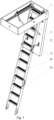
- the object of the invention is a connector for articulated and fixed components of a structural element, and in particular for attic stairs.
- Attic stairs where a hatch is suspended from the first segment of stairs using at least two pairs of connectors, which together with the first segment of the stairs and the hatch constitute a four-bar linkage system has been disclosed in PL228252B1 , or EP2754771A1 .
- the connectors used to suspend the hatch are attached to it using hook brackets, and each has a bearing seat for an extension seated in the connector used to suspend the hatch.
- the assembly opening for this seat is covered by an insert which includes a bearing fill surface and is snap mounted in the hook connector body.
- the hook connector bearing seat has a pass-through opening on both sides, and the extension of the connector used to suspend the hatch terminates with a flange with a larger diameter than the diameter of the seat.
- Another connector for an articulated and a fixed component of a structural element is known from PL67349Y1 , this connector comprises a flat bar with a latching element, a base plate including a pin passing through a hole in the flat bar.
- the invention aims to prepare a connector for components of a structural element which will enable these components to be detached simply and quickly.
- the connector construction also makes it possible to lock the connection of the components against unintentional detachment and this is achieved using only the connector without applying additional locking elements.
- the present invention is a connector according to claim 1.
- This connector comprises a bracket and a flat bar terminating with a latching element being a hook, wherein the connector is an element connecting an articulated component with a fixed component of a structural element.
- the connector bracket is mounted in a hole in the flat panel of the articulated component and comprises a base with a plate with at least one latching foot. The lower gap for the hole edge in the flat panel is located between the latching foot and the plate.
- the bracket base is fixed in the hole using the lock.
- the lock includes a locking foot which fills the hole in the flat panel which already holds one of the base latching feet. Once the lock is inserted into the hole, the lock and the base are connected by at least one coupling or glue.
- the bracket also includes a coaxial opening in the base and the lock wherein the pin used to suspend the flat bar hook is inserted into.
- the bracket is made out of plastic.
- the bracket also includes a gap, running perpendicular to the pin insertion direction, where the flat bar hook is located.
- the other end of the flat bar terminating with a hook is mounted to the fixed component in a manner making it possible to move the articulated component together with the flat bar relative to the fixed component.
- the articulated component When the articulated component is in an essentially vertical position relative to the fixed component, it may be lifted up slightly and the pin, seated earlier in the hook socket, is guided along the inner surface of the hook in the direction of the fixed component.
- the hook travels along the bracket gap, until the articulated component detaches from the fixed component. In a position where the articulated component is slightly tilted, the hook cannot travel in the bracket gap as it is locked by the stop face of the bracket base, and the articulated component remains attached to the fixed component.
- the connector prevents unintentional detachment of the articulated component from the fixed component.
- the components may be locked by tilting the articulated component relative to the fixed component whilst connecting the flat bar to the bracket, whereas the components may be unlocked by aligning the articulated element essentially vertically relative to the fixed component, wherein a tilted position of the articulated component is a natural use position for a structural element.
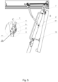
- Closing hatch 2 includes at least two brackets comprising a base 3 and lock 4, which are seated in hole 21 of closing hatch 2.
- the base includes plate 31 with two latching feet 32 with lower gap 33 for hole 21 edge in closing hatch 2 located between plate 31 and each latching foot 32.
- Lock 4 includes locking foot 43 which fills hole 21 in closing hatch 2 which already holds one of the latching feet 32, locking bracket base 3 in place in the bracket locked position.
- Both base 3 and lock 4 include shaped faces, which ensure lock 4 is guided during assembly into the correct position in base 3.
- Lock 4 also includes couplings 41, 42, and base 3 includes coupling 34. During lock insertion into the hole the couplings flex, and in base 3 locked position they are flush with appropriate base 3 and lock 4 surfaces fixing the bracket in closing hatch 2 hole.
- On an inside wall of a frame element of attic stairs box 1 is hinge hanger 5 on which ladder segments 61, 62, 63 are suspended.
- Flat bar 7 terminating with hook 71, with pin 8 seated in a coaxial holes of base 3 and lock 4 in its seat is suspended from the same hanger 5.
- Flat bar 7 terminating with hook 71, is in gap 9 of the bracket, wherein pin 8 is perpendicular to the longitudinal direction of said gap 9.
- hook 71 and the bracket makes it possible to detach closing hatch 2 from the attic stairs or to lock it in the attic stairs' use position.
- Closing hatch 2 is in an essentially vertical position relative to box 1 of the attic stairs, when closing hatch 2 and lower flat bar 10 are not attached. Then closing hatch 2 may be slightly lifted up, and pin 8 is guided along hook 71 inner surface towards attic stairs box 1. At the same time hook 71 travels along bracket gap 9, until closing hatch 2 detaches from the attic stairs.
- closing hatch 2 In the attic stairs' use position, closing hatch 2 assumes its use position, that is a position where it is tilted relative to attic stairs box 1.
- the closing hatch in a tilted position means it is attached by lower flat bars 10. In such closing hatch 2 position, hook 7 cannot travel in bracket gap 9 as it is locked by stop face 35 of bracket base 3 plate 31, and closing hatch 2 remains attached to the attic stairs.
Landscapes
- Engineering & Computer Science (AREA)
- Architecture (AREA)
- Mechanical Engineering (AREA)
- Structural Engineering (AREA)
- Civil Engineering (AREA)
- Ladders (AREA)
- Hooks, Suction Cups, And Attachment By Adhesive Means (AREA)
Claims (7)
- Verbinder für ein bewegliches und ein feststehendes Konstruktionselement. Der Verbinder besteht aus mindestens einer Halterung (3, 4) und mindestens einer Flacheisenstange (7, 10), wobei die Flacheisenstange ein Fangelement (71) aufweist, wobei die Halterung (3, 4) und die Flacheisenstange (7, 10) zur Befestigung an einer beweglichen und einer feststehenden Baugruppe ausgebildet sind, wobei die Halterung (3, 4) einen in der Aufnahme des Fangelements (71) der Flacheisenstange (7, 10) sitzenden Längsstift (8) aufweist, dadurch gekennzeichnet, dass das Fangelement (71) ein Haken ist und quer zur Richtung der Aufnahme des Längsstiftes (8) in der Halterung (3, 4) ein Schlitz (9) der Halterung vorhanden ist und in dem Schlitz (9) mindestens eine Rückhaltewand (35) des Bodens (31) der Halterung für das Fangelement (71) vorhanden ist, die in der Betriebsstellung des beweglichen Baugruppe den Austritt des Fangelements (71) aus der Halterung verhindert.
- Verbinder nach Anspruch 1, dadurch gekennzeichnet, dass die Halterung aus einer Basis (3) aufgebaut ist, wobei der Boden (31) der Basis (3) mit Mitteln versehen ist, um sie in der Montageposition in mindestens ein Loch (21) der flachen Trennwand der beweglichen Baugruppe (2) einzusetzen.
- Verbinder nach Anspruch 2, dadurch gekennzeichnet, dass das Mittel zum Aufsetzen der Halterung in der Montageposition mindestens ein Anschlagfuß (32) ist und zwischen dem Boden (31) der Basis (3) und jedem Anschlagfuß (32) ein unterer Schlitz (33) für den Rand des entsprechenden Lochs (21) in der flachen Trennwand der beweglichen Baugruppe (2) vorhanden ist.
- Verbinder nach Anspruch 1 oder 2 oder 3, dadurch gekennzeichnet, dass die Halterung eine Verriegelungsvorrichtung (4) der Basis aufweist, wobei die Halterung eine verriegelte Position einnimmt, wenn die Verriegelungsvorrichtung (4) und die Basis (3) miteinander verbunden sind.
- Verbinder nach Anspruch 4, dadurch gekennzeichnet, dass die Verriegelungsvorrichtung (4) einen Verriegelungsfuß (43) zum Ausfüllen eines Lochs (21) in der flachen Trennwand der beweglichen Baugruppe (2) aufweist, in dem sich einer der Rastfüße (32) befindet, der die freie Bewegung der Basis (3) der Halterung in der verriegelten Position der Halterung blockiert.
- Verbinder nach Anspruch 4 oder 5, dadurch gekennzeichnet, dass das Verriegelungsvorrichtung (4) und die Basis (3) durch mindestens eine Sperre (34, 41, 42) miteinander verbunden sind.
- Verbinder nach Anspruch 4 oder 5, oder 6 dadurch gekennzeichnet, dass die Verriegelungsvorrichtung (4) und die Basis (3) durch einen Klebstoff miteinander verbunden sind.
Applications Claiming Priority (1)
| Application Number | Priority Date | Filing Date | Title |
|---|---|---|---|
| PL440748A PL440748A1 (pl) | 2022-03-24 | 2022-03-24 | Łącznik podzespołów ruchomego i stałego elementu konstrukcyjnego zwłaszcza schodów strychowych |
Publications (2)
| Publication Number | Publication Date |
|---|---|
| EP4249716A1 EP4249716A1 (de) | 2023-09-27 |
| EP4249716B1 true EP4249716B1 (de) | 2024-10-16 |
Family
ID=87760174
Family Applications (1)
| Application Number | Title | Priority Date | Filing Date |
|---|---|---|---|
| EP23163017.9A Active EP4249716B1 (de) | 2022-03-24 | 2023-03-21 | Verbinder für gelenkige und feste komponenten von einem strukturelement, insbesondere für dachbodentreppen |
Country Status (2)
| Country | Link |
|---|---|
| EP (1) | EP4249716B1 (de) |
| PL (1) | PL440748A1 (de) |
Citations (1)
| Publication number | Priority date | Publication date | Assignee | Title |
|---|---|---|---|---|
| EP1035268A2 (de) * | 1999-03-11 | 2000-09-13 | Ming Dr. Gao | Motorangetriebene Treppen |
Family Cites Families (3)
| Publication number | Priority date | Publication date | Assignee | Title |
|---|---|---|---|---|
| PL67701Y1 (pl) * | 2008-02-11 | 2015-03-31 | Nowak Alojzy Przedsiębiorstwo Okuć Meblowych I Konstrukcji Lekkich | Mechanizm otwierający i zamykający skrzynię mebla |
| PL67349Y1 (pl) * | 2012-05-14 | 2014-08-29 | Okuć Meblowych Stalmot Spółka Akcyjna Fab | Mechanizm przestawnego oparcia mebla |
| PL228252B1 (pl) | 2013-01-14 | 2018-03-30 | Fakro Pp Spolka Z Ograniczona Odpowiedzialnoscia | Schody składane, zwłaszcza lekkie, drewniane |
-
2022
- 2022-03-24 PL PL440748A patent/PL440748A1/pl unknown
-
2023
- 2023-03-21 EP EP23163017.9A patent/EP4249716B1/de active Active
Patent Citations (1)
| Publication number | Priority date | Publication date | Assignee | Title |
|---|---|---|---|---|
| EP1035268A2 (de) * | 1999-03-11 | 2000-09-13 | Ming Dr. Gao | Motorangetriebene Treppen |
Also Published As
| Publication number | Publication date |
|---|---|
| EP4249716A1 (de) | 2023-09-27 |
| PL440748A1 (pl) | 2023-09-25 |
Similar Documents
| Publication | Publication Date | Title |
|---|---|---|
| CN102947601B (zh) | 用于与框架相互连结的滑动组件 | |
| US10533359B2 (en) | Method of assembling a window balance system | |
| CA2377526C (en) | Segmented garage door and hinges | |
| SK286426B6 (sk) | Podperné prostriedky na tieniace zariadenie | |
| EP3680416B1 (de) | Verbindungselement für eine abdeckungsanordnung zur verwendung in einer dachfensteranordnung und verfahren zum abdichten einer dachfensteranordnung | |
| CN110612376B (zh) | 用于窗户的铰链、包括一组这种铰链的窗户及安装这种窗户的方法 | |
| US5921307A (en) | Garage door hinge | |
| MXPA06014606A (es) | Cabina de ascensor y metodo de construccion de la misma. | |
| EP4249716B1 (de) | Verbinder für gelenkige und feste komponenten von einem strukturelement, insbesondere für dachbodentreppen | |
| PL176813B1 (pl) | Urządzenie łączące do montażu skrzydła okna dachowego w ościeżnicy | |
| CN111005491A (zh) | 顶板支撑装置以及顶板支撑组件 | |
| EP4249725A1 (de) | Halterung | |
| US12559983B2 (en) | Box construction lock | |
| KR20190084324A (ko) | 2개의 개폐기 캐비닛 프레임워크의 연결을 위한 연결 조립체 | |
| EP4249698B1 (de) | Dachbodentreppe mit stützbalken | |
| KR102224241B1 (ko) | 미닫이식 도어의 롤러 브래킷 장착구조 | |
| KR20070077305A (ko) | 보강재가 삽입된 창호 연결구 및 이를 이용한 창호구조 | |
| KR200307748Y1 (ko) | 문틀의 프레임 연결구 | |
| JPH11149250A (ja) | ディスプレイなどの支持構造及び支持具 | |
| CN212076121U (zh) | 具有安装配件的电梯门套 | |
| CN100543260C (zh) | 用于家具门的具有制动臂的设备 | |
| KR20230068856A (ko) | 수납장의 슬라이딩 도어용 코너 연결구 및 수납장용 슬라이딩 도어 | |
| EP1335096B1 (de) | tor mit verbesserten horizontalen sektionen | |
| EP2933419B1 (de) | Fensterprodukte | |
| CN210049751U (zh) | 一种新型门窗五金件固定结构 |
Legal Events
| Date | Code | Title | Description |
|---|---|---|---|
| PUAI | Public reference made under article 153(3) epc to a published international application that has entered the european phase |
Free format text: ORIGINAL CODE: 0009012 |
|
| STAA | Information on the status of an ep patent application or granted ep patent |
Free format text: STATUS: THE APPLICATION HAS BEEN PUBLISHED |
|
| STAA | Information on the status of an ep patent application or granted ep patent |
Free format text: STATUS: REQUEST FOR EXAMINATION WAS MADE |
|
| AK | Designated contracting states |
Kind code of ref document: A1 Designated state(s): AL AT BE BG CH CY CZ DE DK EE ES FI FR GB GR HR HU IE IS IT LI LT LU LV MC ME MK MT NL NO PL PT RO RS SE SI SK SM TR |
|
| 17P | Request for examination filed |
Effective date: 20230913 |
|
| RBV | Designated contracting states (corrected) |
Designated state(s): AL AT BE BG CH CY CZ DE DK EE ES FI FR GB GR HR HU IE IS IT LI LT LU LV MC ME MK MT NL NO PL PT RO RS SE SI SK SM TR |
|
| GRAP | Despatch of communication of intention to grant a patent |
Free format text: ORIGINAL CODE: EPIDOSNIGR1 |
|
| STAA | Information on the status of an ep patent application or granted ep patent |
Free format text: STATUS: GRANT OF PATENT IS INTENDED |
|
| INTG | Intention to grant announced |
Effective date: 20240723 |
|
| GRAS | Grant fee paid |
Free format text: ORIGINAL CODE: EPIDOSNIGR3 |
|
| GRAA | (expected) grant |
Free format text: ORIGINAL CODE: 0009210 |
|
| STAA | Information on the status of an ep patent application or granted ep patent |
Free format text: STATUS: THE PATENT HAS BEEN GRANTED |
|
| AK | Designated contracting states |
Kind code of ref document: B1 Designated state(s): AL AT BE BG CH CY CZ DE DK EE ES FI FR GB GR HR HU IE IS IT LI LT LU LV MC ME MK MT NL NO PL PT RO RS SE SI SK SM TR |
|
| REG | Reference to a national code |
Ref country code: GB Ref legal event code: FG4D |
|
| REG | Reference to a national code |
Ref country code: CH Ref legal event code: EP Ref country code: DE Ref legal event code: R096 Ref document number: 602023000727 Country of ref document: DE |
|
| REG | Reference to a national code |
Ref country code: IE Ref legal event code: FG4D |
|
| REG | Reference to a national code |
Ref country code: NL Ref legal event code: FP |
|
| REG | Reference to a national code |
Ref country code: LT Ref legal event code: MG9D |
|
| REG | Reference to a national code |
Ref country code: AT Ref legal event code: MK05 Ref document number: 1733039 Country of ref document: AT Kind code of ref document: T Effective date: 20241016 |
|
| PG25 | Lapsed in a contracting state [announced via postgrant information from national office to epo] |
Ref country code: HR Free format text: LAPSE BECAUSE OF FAILURE TO SUBMIT A TRANSLATION OF THE DESCRIPTION OR TO PAY THE FEE WITHIN THE PRESCRIBED TIME-LIMIT Effective date: 20241016 Ref country code: IS Free format text: LAPSE BECAUSE OF FAILURE TO SUBMIT A TRANSLATION OF THE DESCRIPTION OR TO PAY THE FEE WITHIN THE PRESCRIBED TIME-LIMIT Effective date: 20250216 Ref country code: PT Free format text: LAPSE BECAUSE OF FAILURE TO SUBMIT A TRANSLATION OF THE DESCRIPTION OR TO PAY THE FEE WITHIN THE PRESCRIBED TIME-LIMIT Effective date: 20250217 |
|
| PG25 | Lapsed in a contracting state [announced via postgrant information from national office to epo] |
Ref country code: FI Free format text: LAPSE BECAUSE OF FAILURE TO SUBMIT A TRANSLATION OF THE DESCRIPTION OR TO PAY THE FEE WITHIN THE PRESCRIBED TIME-LIMIT Effective date: 20241016 |
|
| PG25 | Lapsed in a contracting state [announced via postgrant information from national office to epo] |
Ref country code: BG Free format text: LAPSE BECAUSE OF FAILURE TO SUBMIT A TRANSLATION OF THE DESCRIPTION OR TO PAY THE FEE WITHIN THE PRESCRIBED TIME-LIMIT Effective date: 20241016 |
|
| PG25 | Lapsed in a contracting state [announced via postgrant information from national office to epo] |
Ref country code: ES Free format text: LAPSE BECAUSE OF FAILURE TO SUBMIT A TRANSLATION OF THE DESCRIPTION OR TO PAY THE FEE WITHIN THE PRESCRIBED TIME-LIMIT Effective date: 20241016 |
|
| PG25 | Lapsed in a contracting state [announced via postgrant information from national office to epo] |
Ref country code: NO Free format text: LAPSE BECAUSE OF FAILURE TO SUBMIT A TRANSLATION OF THE DESCRIPTION OR TO PAY THE FEE WITHIN THE PRESCRIBED TIME-LIMIT Effective date: 20250116 |
|
| PG25 | Lapsed in a contracting state [announced via postgrant information from national office to epo] |
Ref country code: LV Free format text: LAPSE BECAUSE OF FAILURE TO SUBMIT A TRANSLATION OF THE DESCRIPTION OR TO PAY THE FEE WITHIN THE PRESCRIBED TIME-LIMIT Effective date: 20241016 Ref country code: AT Free format text: LAPSE BECAUSE OF FAILURE TO SUBMIT A TRANSLATION OF THE DESCRIPTION OR TO PAY THE FEE WITHIN THE PRESCRIBED TIME-LIMIT Effective date: 20241016 Ref country code: GR Free format text: LAPSE BECAUSE OF FAILURE TO SUBMIT A TRANSLATION OF THE DESCRIPTION OR TO PAY THE FEE WITHIN THE PRESCRIBED TIME-LIMIT Effective date: 20250117 |
|
| PG25 | Lapsed in a contracting state [announced via postgrant information from national office to epo] |
Ref country code: PL Free format text: LAPSE BECAUSE OF FAILURE TO SUBMIT A TRANSLATION OF THE DESCRIPTION OR TO PAY THE FEE WITHIN THE PRESCRIBED TIME-LIMIT Effective date: 20241016 |
|
| PG25 | Lapsed in a contracting state [announced via postgrant information from national office to epo] |
Ref country code: RS Free format text: LAPSE BECAUSE OF FAILURE TO SUBMIT A TRANSLATION OF THE DESCRIPTION OR TO PAY THE FEE WITHIN THE PRESCRIBED TIME-LIMIT Effective date: 20250116 |
|
| PG25 | Lapsed in a contracting state [announced via postgrant information from national office to epo] |
Ref country code: SM Free format text: LAPSE BECAUSE OF FAILURE TO SUBMIT A TRANSLATION OF THE DESCRIPTION OR TO PAY THE FEE WITHIN THE PRESCRIBED TIME-LIMIT Effective date: 20241016 |
|
| PG25 | Lapsed in a contracting state [announced via postgrant information from national office to epo] |
Ref country code: DK Free format text: LAPSE BECAUSE OF FAILURE TO SUBMIT A TRANSLATION OF THE DESCRIPTION OR TO PAY THE FEE WITHIN THE PRESCRIBED TIME-LIMIT Effective date: 20241016 |
|
| REG | Reference to a national code |
Ref country code: DE Ref legal event code: R097 Ref document number: 602023000727 Country of ref document: DE |
|
| PG25 | Lapsed in a contracting state [announced via postgrant information from national office to epo] |
Ref country code: EE Free format text: LAPSE BECAUSE OF FAILURE TO SUBMIT A TRANSLATION OF THE DESCRIPTION OR TO PAY THE FEE WITHIN THE PRESCRIBED TIME-LIMIT Effective date: 20241016 |
|
| PG25 | Lapsed in a contracting state [announced via postgrant information from national office to epo] |
Ref country code: RO Free format text: LAPSE BECAUSE OF FAILURE TO SUBMIT A TRANSLATION OF THE DESCRIPTION OR TO PAY THE FEE WITHIN THE PRESCRIBED TIME-LIMIT Effective date: 20241016 |
|
| PG25 | Lapsed in a contracting state [announced via postgrant information from national office to epo] |
Ref country code: SK Free format text: LAPSE BECAUSE OF FAILURE TO SUBMIT A TRANSLATION OF THE DESCRIPTION OR TO PAY THE FEE WITHIN THE PRESCRIBED TIME-LIMIT Effective date: 20241016 |
|
| PG25 | Lapsed in a contracting state [announced via postgrant information from national office to epo] |
Ref country code: CZ Free format text: LAPSE BECAUSE OF FAILURE TO SUBMIT A TRANSLATION OF THE DESCRIPTION OR TO PAY THE FEE WITHIN THE PRESCRIBED TIME-LIMIT Effective date: 20241016 |
|
| PG25 | Lapsed in a contracting state [announced via postgrant information from national office to epo] |
Ref country code: IT Free format text: LAPSE BECAUSE OF FAILURE TO SUBMIT A TRANSLATION OF THE DESCRIPTION OR TO PAY THE FEE WITHIN THE PRESCRIBED TIME-LIMIT Effective date: 20241016 |
|
| PLBE | No opposition filed within time limit |
Free format text: ORIGINAL CODE: 0009261 |
|
| STAA | Information on the status of an ep patent application or granted ep patent |
Free format text: STATUS: NO OPPOSITION FILED WITHIN TIME LIMIT |
|
| PG25 | Lapsed in a contracting state [announced via postgrant information from national office to epo] |
Ref country code: SE Free format text: LAPSE BECAUSE OF FAILURE TO SUBMIT A TRANSLATION OF THE DESCRIPTION OR TO PAY THE FEE WITHIN THE PRESCRIBED TIME-LIMIT Effective date: 20241016 |
|
| 26N | No opposition filed |
Effective date: 20250717 |
|
| PG25 | Lapsed in a contracting state [announced via postgrant information from national office to epo] |
Ref country code: MC Free format text: LAPSE BECAUSE OF FAILURE TO SUBMIT A TRANSLATION OF THE DESCRIPTION OR TO PAY THE FEE WITHIN THE PRESCRIBED TIME-LIMIT Effective date: 20241016 |
|
| PG25 | Lapsed in a contracting state [announced via postgrant information from national office to epo] |
Ref country code: LU Free format text: LAPSE BECAUSE OF NON-PAYMENT OF DUE FEES Effective date: 20250321 |
|
| PG25 | Lapsed in a contracting state [announced via postgrant information from national office to epo] |
Ref country code: IE Free format text: LAPSE BECAUSE OF NON-PAYMENT OF DUE FEES Effective date: 20250321 |
|
| PGFP | Annual fee paid to national office [announced via postgrant information from national office to epo] |
Ref country code: NL Payment date: 20260219 Year of fee payment: 4 |
|
| PGFP | Annual fee paid to national office [announced via postgrant information from national office to epo] |
Ref country code: DE Payment date: 20260219 Year of fee payment: 4 |
|
| PGFP | Annual fee paid to national office [announced via postgrant information from national office to epo] |
Ref country code: BE Payment date: 20260219 Year of fee payment: 4 |
|
| PGFP | Annual fee paid to national office [announced via postgrant information from national office to epo] |
Ref country code: FR Payment date: 20260217 Year of fee payment: 4 |