EP4249726A2 - Verfahren und system zur ermöglichung von kernorientierungsdatenübertragung an der oberfläche - Google Patents
Verfahren und system zur ermöglichung von kernorientierungsdatenübertragung an der oberfläche Download PDFInfo
- Publication number
- EP4249726A2 EP4249726A2 EP23179712.7A EP23179712A EP4249726A2 EP 4249726 A2 EP4249726 A2 EP 4249726A2 EP 23179712 A EP23179712 A EP 23179712A EP 4249726 A2 EP4249726 A2 EP 4249726A2
- Authority
- EP
- European Patent Office
- Prior art keywords
- core
- instrument
- orientation
- guide
- axis
- Prior art date
- Legal status (The legal status is an assumption and is not a legal conclusion. Google has not performed a legal analysis and makes no representation as to the accuracy of the status listed.)
- Withdrawn
Links
Images


Classifications
-
- E—FIXED CONSTRUCTIONS
- E21—EARTH OR ROCK DRILLING; MINING
- E21B—EARTH OR ROCK DRILLING; OBTAINING OIL, GAS, WATER, SOLUBLE OR MELTABLE MATERIALS OR A SLURRY OF MINERALS FROM WELLS
- E21B47/00—Survey of boreholes or wells
- E21B47/09—Locating or determining the position of objects in boreholes or wells, e.g. the position of an extending arm; Identifying the free or blocked portions of pipes
-
- E—FIXED CONSTRUCTIONS
- E21—EARTH OR ROCK DRILLING; MINING
- E21B—EARTH OR ROCK DRILLING; OBTAINING OIL, GAS, WATER, SOLUBLE OR MELTABLE MATERIALS OR A SLURRY OF MINERALS FROM WELLS
- E21B25/00—Apparatus for obtaining or removing undisturbed cores, e.g. core barrels or core extractors
- E21B25/16—Apparatus for obtaining or removing undisturbed cores, e.g. core barrels or core extractors for obtaining oriented cores
-
- E—FIXED CONSTRUCTIONS
- E21—EARTH OR ROCK DRILLING; MINING
- E21B—EARTH OR ROCK DRILLING; OBTAINING OIL, GAS, WATER, SOLUBLE OR MELTABLE MATERIALS OR A SLURRY OF MINERALS FROM WELLS
- E21B25/00—Apparatus for obtaining or removing undisturbed cores, e.g. core barrels or core extractors
- E21B25/005—Above ground means for handling the core, e.g. for extracting the core from the core barrel
-
- E—FIXED CONSTRUCTIONS
- E21—EARTH OR ROCK DRILLING; MINING
- E21B—EARTH OR ROCK DRILLING; OBTAINING OIL, GAS, WATER, SOLUBLE OR MELTABLE MATERIALS OR A SLURRY OF MINERALS FROM WELLS
- E21B47/00—Survey of boreholes or wells
- E21B47/02—Determining slope or direction
- E21B47/024—Determining slope or direction of devices in the borehole
-
- E—FIXED CONSTRUCTIONS
- E21—EARTH OR ROCK DRILLING; MINING
- E21B—EARTH OR ROCK DRILLING; OBTAINING OIL, GAS, WATER, SOLUBLE OR MELTABLE MATERIALS OR A SLURRY OF MINERALS FROM WELLS
- E21B47/00—Survey of boreholes or wells
- E21B47/26—Storing data down-hole, e.g. in a memory or on a record carrier
Definitions
- a method and system are disclosed for enabling at surface core orientation data transfer from a contactless orientation system.
- Core sampling is employed to allow geological surveying of the ground for the purposes of exploration and/or mining development. Analysis of the composition of the core sample provides information of the geological structures and composition of the surrounding ground. In order to maximise the usefulness of this information it is necessary to have knowledge of the orientation of the core sample relative to the ground from which it is extracted.
- Back end core orientation systems also known as contactless core orientation systems
- contactless core orientation systems usually rely on gyroscopic, magnetic or gravitational sensors and devices for determining core orientation.
- These systems do not leave a physical mark of orientation on the core sample at the time of recording the core orientation or otherwise provide a permanent record of the core orientation that is carried by or associated with the sample.
- Such a physical mark or record is required by a geologist to enable them to determine the orientation of the core sample.
- the process of making such a core orientation record is performed at the surface, usually by the use of marking guides and jigs which support an inner core tube together with its corresponding backend or contactless orientation system.
- the jig allows the operator to rotate the core sample about the core axis so that at a predetermined point (for example, bottom dead centre) is orientated to a known position (typically either the 180° position or the 0° position).
- the operator then physically marks the core sample on the core face, or the outer circumferential surface or both with a pencil or scribe denoting the location at that point.
- a geologist views the core sample they are able to easily discern the in-situ rotational position of the core sample.
- a contactless orientation system coupled with an inner core tube to one or more record carriers on or associated with a core sample held in the core tube, the core sample having a longitudinal core axis and a core face accessible from an end of the inner core tube, the method comprising:
- generating correlation information comprises referencing the rotational position of the known point and the in-situ rotational orientation known to the contactless orientation system to a common reference point.
- generating correlation information comprises operating the contactless orientation system to facilitate positioning of the core sample about the core axis so that the in situ orientation coincides with the orientation of the common reference point.
- generating correlation information comprises rotationally aligning the known point with the common reference point.
- operating the instrument comprises using the instrument guide to move the instrument in a direction parallel to the core axis to contact the core face wherein on contact with the core face the instrument constitutes, or is capable of producing, a record carrier provided with the transferred orientation data.
- generating the correlation information comprises electronically determining the rotational position of the known point.
- generating the correlation information comprises electronically transferring the orientation data from the core orientation system to the instrument.
- a contactless orientation system coupled with an inner core tube to one or more record carriers on or associated with a core sample held in the core tube, the core sample having a longitudinal core axis and a core face accessible from an end of the inner core tube, the method comprising:
- the method comprises prior to moving, generating correlation information between a known point on the instrument guide about the guide axis and core orientation data known to the contactless core orientation system.
- the method comprises operating the instrument supported in or by the instrument guide to: act as the record carrier; or generate the record carrier provided with, or otherwise having transferred to it, the correlation information enabling orientation of the core sample to its in-situ orientation when released from the core tube.
- the method comprises generating correlation data comprises rotationally aligning the known point with the core orientation a common reference point about the core axis.
- using the instrument guide comprises engaging the instrument with the instrument guide and moving the instrument relative to the core face and parallel to the core axis to cause contact between the core face and the instrument.
- moving the instrument parallel to the core axis relative to the core face comprises either (a) moving the instrument along, through or within the instrument guide relative to the core face to cause contact between the core face and the instrument; or (b) moving the instrument guide relative to the core face to cause contact between the core face and the instrument.
- the method comprises demountably engaging the instrument with the instrument guide wherein after contact with the core face the instruments can be removed from the instrument guide.
- the method comprises removing the instrument from the instrument guide after contact with the core face.
- the method comprises recording on or in the instrument, header data relating to the core sample.
- the method comprises manually recording the header data on the instrument.
- the method comprises wireless transferring header data for recording in the instrument or on the record carrier.
- the method comprises electronically recording in or on the record carrier audit data relating to the core sample.
- the method comprises electronically recording in or on the record carrier, header data and audit data relating to the core sample.
- recording audit data comprise recording one more of: (a) the time of day when the instrument was moved in a direction parallel to the core axis to contact the core face; (b) the date of moving the instrument in a direction parallel to the core axis to contact the core face; (c) the geographic location of the core sample in relation to which the method is performed; (d) a degree and direction of rotation of the instrument guide relative to the core tube about the core axis during the referencing of the rotational positions of the points and moving of the parallel to the core axis to cause contact between the core face and the instrument; (e) tool face of the core sample.
- the method comprises arranging the instrument to record data pertaining to the profile of the core face.
- the record carrier comprises an electronic image captured by the instrument of the core face and wherein the known point is visually represented on the image.
- the record carrier further comprises electronic data pertaining to the rotational orientation of the known point.
- the instrument comprises a plastically deformable pad or a plurality of linearly translatable pins which on contact with the core face are capable of recording data pertaining to the profile of the core face.
- the method comprises providing the instrument with an electronic memory device capable of storing or processing data communicated by the contactless orientation system.
- a contactless orientation system coupled with an inner core tube to one or more record carriers associated with a core sample held in the core tube, the core sample having a longitudinal core axis and a core face visible from an end of the inner core tube, the system comprising:
- the instrument and the instrument guide are provided with respective coupling parts that enable demountable coupling of the instrument to the instrument guide in known rotational juxtaposition about the guide axis.
- the instrument comprises one or both of: (a) a core face profile recording system; and (b) a scribe or marker capable of placing a mark on the core face.
- the core face profile recording system comprises either (a) a plurality of axially displaceable pins or (b) a pad of plasticised material capable of taking an imprint of the core face.
- the instrument comprises a surface on which header data can be manually transcribed.
- the method comprises a rotation sensing device capable of detecting rotation of the instrument guide about the guide axis.
- the instrument comprises an electronic memory device capable of recording one or both of (a) header data, and (b) audit data relating to the core sample.
- a contactless orientation system coupled with an inner core tube to an electronically recordable file associated with a core sample held in the core tube, the core sample having a longitudinal core axis and a core face visible from an end of the inner core tube, the method comprising:
- generating the rotational position reference data comprises wirelessly communicating the rotational position of the point on the core sample about the core axis having a position known to the contactless orientation system rotational position.
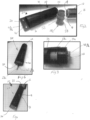
- Figures 1 and 2 depict an embodiment of a system 10 for enabling at surface core orientation data transfer from a contactless core orientation system 11 coupled with a core tube 12.
- a core sample 14 is captured in the core tube 12.
- the core sample 14 has a longitudinal core axis 16 and an exposed core face 18.
- the core orientation system may be coupled to or otherwise housed in an up-hole end of a core tube 12.
- the specific nature of the core orientation system 11 is not material to the disclosed system and method.
- a contactless core orientation system is the REFLEX ACT III orientation system (see for example http://reflexnow.com/act-III/ ).
- This embodiment of the system 10 comprises an instrument guide 20 having a first end 22 and an opposite end 24 that are or can be arranged to lie on a common guide axis 26.
- the guide axis 26 is parallel to the core axis 16.
- the instrument guide 20 is configured so that when the first end 22 is coupled or otherwise engaged with the core tube 12, the core face 18 lies between the first and second end 22 and 24. This is shown for example in present Figure 4 .
- the system 10 also includes an instrument 28a ( Figures 1-5 ) that is coupled with the instrument guide 20.
- the instrument 28a is supported or coupled in a manner wherein the instrument guide 20 holds the instrument 28a in alignment with the core axis.
- the guide 20 facilitates motion of the instrument 28a in a direction parallel to the core axis 16 to a location where the instrument 28a contacts the core surface 18.
- the instrument guide 20 is composed of a first sleeve 30 and a second sleeve 32.
- the sleeves 30 and 32 are releasably connectable together. In this example this is by way of complementary screw threads 34a and 34b.
- the first sleeve 30 is formed with an inner diameter which is slightly larger than the outer diameter of the core tube 12. This enables the instrument guide 20 to engage the core tube 12 with minimal radial play.
- a number of viewing ports 36 are formed in the sleeve 30 near an end at which the sleeve 30 couples to the sleeve 32.
- Sleeve 32 houses the instrument 28a.
- the instrument 28a is keyed to the sleeve 32 so that it has a known rotational orientation with reference to one or more known reference point P1, P2...Pn (hereinafter referee to in general as known point(s) P), of the system. This is achieved by way of engagement of the instrument 28a with mounting pin 38 provided with the sleeve 32.
- the instrument 28 and the mounting pin 38 are arranged so that the instrument 28a can lock into the sleeve 32 on the mounting pin 38 in only one specific and known orientation about the guide axis 26.
- the system 10 has a rotational position sensor 40, in this example a spirit level 41, to provide an operator with information relating to the rotational position of the known point(s) P of the system 10 about the guide axis 26.
- the point P maybe one of a plurality of known points P1, P2 etc. Further the one or more points P may be either on or referable to the guide 20 or the instrument 28a supported by the guide.
- the senor 40 is attached to the instrument guide 20 near the end 24 of the sleeve 32.
- the system 10 is also provided with an axial passage 42 which is parallel with the axis 26.
- the passage 42 opens onto the end 24.
- the passage 42 is provided to enable receipt of a second or alternative instrument 28b in the form of a china pencil (see Figure 6 ).
- the instrument 28a has a core face profile recording system 44 which comprises a set of pins 46 and a marker in the form of a pencil 48.
- the pins 46 are frictionally retained within a body 50 of the instrument 28a and are able to slide lineally in a direction parallel to the guide axis 26.
- An outer surface 52 of the body 50 is provided with a compass or bearing scale 54 (see Fig 5 ).
- One such point P1 may be the rotational position of the marker 48 of the instrument 28a about the guide axis 26.
- An alternate or additional point P2 may be the rotational position of the axis of the passage 42 about position of the guide axis 26.
- both of these points P1 and P2 lie on the same radius of the guide axis 26. That is, the points P1 and P2 have the same rotational position about the guide axis 26.
- the instrument 28a also includes a demountable cap 56 (see Figure 2 ) that can be mounted on the end of the body 50 from which the pins 46 protrude.
- the cap 56 when fitted protects the pins 46 from being accidentally displaced in the axial direction.
- the cap 56 is also provided with a surface 58 which can be manually marked for example by an indelible marker with header data relating to the core sample.
- Header data may include: identification data (e.g. a hole number) of the hole from which the core sample 18 is obtained; the driller ID; and the depth of hole at which the sample was extracted. Further details of the instrument 28a may be obtained from US publication number 201 0/0230165 the contents of which is incorporated herein by way of reference.
- Figure 7 shows in a very broad sense an embodiment of the disclosed method 100 for enabling at surface core orientation data transfer from a contactless orientation system 11 coupled with inner core tube 12 to one or more record carriers.
- the instrument 28a constitutes a record carrier.
- the core sample 14 may also constitute a record carrier.
- the record carrier may comprise an electronic memory storage device which is attached to the instrument 28, or may be constituted by electronically storable data such as an electronic image.
- This embodiment of the method 100 can be considered as involving three broad steps namely:
- the generation of the correlation information between the positions of the known point P and the core orientation data may be via a common reference point A.
- the step 102 of coupling the instrument guide 20 to the end of the core tube 12 is achieved by mounting or otherwise arranging the instrument guide 20 relative to the core sample 14 so that the core face 18 lies between the first and second end 22 and 24 of the instrument guide 20.
- the end 22 of the guide 20 is simply slid onto and over the core sample 14 and the adjacent portion of the inner core tube 12. This arrangement is shown specifically in Figure 4 .
- Figures 8a-8d are referred to assist in describing steps 104 and 102 of the present embodiment of the method 100. It is assumed that the contactless orientation system 11 was previously operated to log core orientation data being the in situ rotational position of a specific point on the core about the core axis 16 immediately prior to the core breaking operation relative to a known reference.
- the known reference may be, but not is limited to, for example:
- the contactless core orientation system 11 When retrieving the core sample 14 from a drill string and subsequently placing the corresponding core tube 12 on a core table or jig the relative rotational position of the contactless core orientation system 11 and the core sample 14 have not changed. Also the contactless core orientation system 11 by its very nature is able to detect the known reference when at the surface or in the hole.
- the contactless orientation system 11 logs orientation data of the a point on the core 14 relative to bottom dead centre of the bore hole rather than magnetic north or true north.
- Figure 8a shows the gravitational bottom of hole location BH in an angled borehole of the core sample 14 when retrieved from the bore hole and lying horizontally on a core table or jig.
- the core face 18 is front on, the core sample 14 is still in the core tube 12 and the system 11 is attached to the back end of the core tube.
- Point BH shows the location of the bottom of the hole of the core 14 as logged by the system 11 immediately prior to the core breaking operation.
- Point A is a common reference point and in this example corresponds with the location of the bottom of the core sample 14 when at the surface on a core tray. Neither point A nor point BH is physically marked on the core sample 14.
- the guide 20 is not coupled to the core tube 12 at this time.
- the in situ gravitational bottom of hole location BH of the core sample 14, while known to the contactless core orientation system 11 is at a random rotational position about the axis 16.
- the point BH is at a bearing of about 300° (or -60°) about the axis 16.
- Figure 8b shows a first step in the correlating the position BH with the position of the know point P. This may also be considered as referencing the core orientation data with or to the known location P. This step involves rotating the core tube 12 and thus the core sample 14 until the point BH is at a known location in this instance the common reference point A which is at a bearing of 180°. Because the contactless orientation system11 knows the location BH, and knows its own location in space, the contactless orientation system 11 can now be operated on the surface to provide feedback to an operator to inform them when the point BH is at the 180° bearing coinciding with point A. This feedback may be by way of audible and/or visual signals emitted by the contactless orientation system 11 or by a handheld or otherwise portable instrument 11 which communicates with the contactless orientation system.
- Figure 8c represents the rotational position of the guide 20 on initial mounting on the core tube 12. Now the respective axes 16 and 26 are collinear. Indeed the axes 16 and 26 will be substantially coaxial.
- the marker 48 which represents a known point P1 on the instrument 28a is initially randomly located about axis 26 when the guide 20 is mounted on the core tube 12. In this example point P1 /marker 48 is shown at a bearing of about 110° about the guide axis 26.
- the instrument 28a is now operated (in this case by using the guide 20 to slide the instrument 28a into contact with the face 18), to generate the record carrier provided with the correlation information. Indeed in this example two record carriers are generated.
- One record carrier 20 is the core 14 while a second independent record carrier is the instrument 28a.
- the core face 18 bearing the mark TD now constitutes a first record carrier of the in situ orientation data of the core sample 14.
- the mark TD is or otherwise constitutes the transferred orientation data from the contactless orientation system 11 to the record carrier.
- the point TD is indicative of the orientation of the known point P and corresponds to or has a known relationship with the in situ orientation of the core sample 14.
- the rotational position of the mark TD is the same as the orientation of the known point P.
- transferred orientation data TD is not a physical mark on the core sample 14 but rather electronically storable data which provides an indication of the in situ orientation of the core sample 14.
- the instrument 28a by virtue of the pins 46 and either the pencil 48 or the hole in which the pencil 48 is held, forms or acts as another independent record carrier bearing correlation information enabling orientation of the core sample 14 to its in situ orientation when released from the core tube 12.
- a geologist can always properly orientate the core sample 14 by matching the profile of the face 18 with the profile of the pins 46 and then rotating/rolling the instrument 28a with the core sample 14 in a horizontal plane so that the location pencil 48 is a bearing of 180°.
- the geologist knows that the lowermost point of the core 14 corresponds with the point BH recorded by the system 11. Therefore even if the mark TD on the core face 18 has been lost the core sample 14 can still be placed in its in situ orientation.
- the instrument 28a can be removed from the guide 20 by decoupling the sleeves 22 and 24 from each other and pulling the instrument 28a off of its mounting key 38.
- the cap 56 may then be attached to the body 50 to protect the pins 46 form accidental displacement. Header data can be manually written onto the surface 58 of the cap 56.
- the instrument 28a is retained with the core sample 12. Thus a new instrument 28a is required for each orientation data transfer.
- the above position procedure for generating the correlation information or otherwise referencing the in situ core orientation for known point P of the system 10 could also be used for vertical boreholes that do not have a gravitational bottom of hole reference position. This requires the use of a contactless orientation system that relies on magnetic north or true north as the known (detectable) reference point.
- the system 10 uses the instrument 28b rather than the instrument 28a.
- the instrument 28a is a consumable single use item whereas the instrument 28b is used to correlate the known point P with the in situ core orientation to effect transfer of the orientation data onto the core face 18 of many core samples 14.
- the instrument 28b solely comprises a longer version of the pencil 48 of the instrument 28a.
- the rotationally referencing method is identical to that described above.
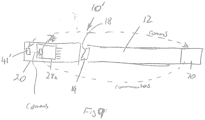
- the instrument 28a may be provided with an electronic memory device 74 (shown schematically in Figure 9 ) enabling the electric recording of one or both of header data and audit data.
- the electronic memory device can be in the form of for example of an RFID chip. This may be embedded in the body 50 of the instrument 28a. Header and/or audit data can be transferred automatically from the contactless orientation system 11 to the electronic memory device.
- the audit data may include for example but is not limited to:
- embodiments of the system 10 may also be provided with one or more accelerometers to detect rotational motion about the axis 26.
- GPS and other digital, magnetic or gyroscopic devices will be placed in the guide 20 rather than the instrument 28a to reduce the overall cost of the consumable product namely, the instrument 28a.
- the instrument 28a in this embodiment is used in exactly the same manner as described above in relation to the first embodiment of the additional step of electronically transferring information from one, or any combination, of: the system 11; the GPS and other digital, magnetic or gyroscopic device in the guide 20; or other instrument such as smart phone.
- the smart phone may be used to enter some or all of the audit data into the electronic memory.
- Figure 9 also provides a schematic representation of an embodiment of the system 10' which enables electronic generation of correlation information enabling the rotational referencing of point P relative to point BH.
- the rotational position sensor 40 is in the form of an electronic rotational orientation system 41' rather than the spirit level described in relation to the first embodiment.
- the contactless core orientation system 11 is connected to the back end of the core tube 12.
- the system 10'/guide 20 will know or be able to determine by itself the rotational position of point P about the guide axis 26.
- the bearing of the point BH about axis 16 is known to, or measurable by, the contactless core orientation system 11 and the bearing of the point the point P is known to, or measurable by, the system 41'.
- the location of point BH relative to point P can be determined i.e. correlation information can be generated enabling the orientation of the core sample 14 to its in situ orientation when released from the core tube 12.
- This may be stored on an electronic memory (such a RFID chip described above) on or in the instrument 28a.
- the method 100 entails, once the core sample 14 and core tube 12 are placed on a core table or rack, with point A representing the lowest rotational position of the core sample 14 on the table, i.e. the 180° bearing position:
- the guide 20 can now be used to cause contact between the instrument 28a and the core face 14 thereby physically marking the core face 14 with the point TD.
- a geologist by accessing a database associated with the core sample 14 knows of the physical point P is offset by ⁇ ° degrees from the reference point (in this case gravitational bottom of the hole).
- the geologist now rotates the core sample 14 about a horizontal axis so that the point P is in the rotational offset position, at which time the core sample 14 will be in its in situ orientation at the time of the core breaking operation.
- This embodiment of system 10' requires that the contactless orientation system 11 and the system 41' are able to communicate to each other the bearing of their respective points BH and P. Either one of the systems 11 or 41' can then determine the position of point P relative to the gravitational bottom of hole, magnetic or true north directional location BH. This is communicated to an electronic memory 74 in or on the instrument 28a either by the system 11 or the system 72.
- Providing WiFi capability in either the system 11, system 41' or indeed the memory 74 also enables header and/or audit data inclusive of course of core orientation data to be automatically uploaded to a centralised data management system or hub. This then enables a geologist to simply access the database and view the information stored in relation to any particular core sample to enable access to auditable data pertaining to the orientation of the core sample.
- the instrument generating the record carrier can be an image capture device locatable within or supported by the guide 20 to obtain an image of a core face 18.
- the guide 20 is arranged on the core tube 12 with the core face 16 intermediate the ends 20 and 24 an image plane of the image capture device will be square on (i.e. perpendicular to) the core axis 16.
- the image capture device can be used to capture an image of the core face 18.
- the image may be a photographic image, a stereoscopic image, or indeed an acoustic, radar, gamma, XRAY Fluorescent (XRF) or other type image, or a combination of two or more of such images.
- XRF XRAY Fluorescent
- the image capture device is arranged so that the point P can be designated at a specific pixel on an image of the core face 18. This pixel appears in a known manner for, example a cross, on the image.
- the image capture device i.e. the instrument
- the image capture device may itself have an inbuilt orientation system which knows and stores information relating to the orientation of the point P about a known reference such as the 180° bearing about a horizontal axis, true North or magnetic north.
- the instrument guide 20 supporting instrument 28a may have an electronic rotational orientation system 41' as described above which can communicate orientation information to the image capture device.
- the instrument 11 knows the in situ orientation data the correlation information relating the rotational position of this point P with or to point BH can be generated as described above in relation to the embodiment in Figure 9 . Further, all of the header and other audit data can also be uploaded to the database or hub. Now when a geologist wishes to analyse this data, they will access, either online or by a separate electronic data carrier, an image of the core face with the marked point P together with the header and audit data. The geologist can then compare the image with the core sample at hand and rotate the core sample to its rotational position about its axis 16 at the time of core break.
- the record carrier is electronic image data enabling display of an image of the core face together with the location of the point P and the correlation information relating the location of point P to the in situ core orientation.
- a geologist can access a database pertaining to the core sample in question, access and display the image of the core sample locate including the point P on the image, view the core face 18 to locate the corresponding point on the core face then using the stored correlation information determine the in-situ orientation of the core sample 14.
- the correlation information may be that the point P on the display is bottom dead centre.
- the record carrier incorporated in the system 10 shown in Figures 1-3 comprises a plurality of pins 46 which provide profile points of the core face 18.
- the profile may be recorded by use of a plasticised material which takes an imprint of the core face 18 on contact.
- the instrument guide 20 is depicted as being in the form of a tube provided with a number of circular viewing ports, different configurations are possible.
- the instrument guide could be provided with a plurality of elongated slots that extend axially between the ends 22 and 24.
- the instrument guide 20 may be of a different shape such as triangular or be provided with flat bottom surface that provides a horizontal positional reference rather than use of a spirit level.
- the system 10 may be provided with a carriage on which the instrument 28a is supported and a lever or other actuator that can be manipulated by an operator to move the carriage linearly along or within the guide 20 to contact the core face 18.
- a core release system such as described in Applicant's co-pending Australian application no. 2015904439 (the contents of which is incorporated herein by way of reference) may be incorporated into the system 10 to assist in releasing the core sample 14 after the transfer of the orientation data.
- the contactless core orientation system has been described as providing at least core orientation data (i.e. azimuth or bearing) it may also provide other information such as hole inclination which can be transferred particularly for embodiments of the disclosed system and method that incorporate electronic data storage.
- a camera may be provided in the instrument 28a described with reference to Figures 1-5 at a location to facilitate image capture of the core face 18.
- the camera can be operated either (a) prior to contact with the core face; (b) both before and at contact with the face; or (c) continuously from before, to the time of contact with the core face.
- Operating the camera as per (b) or (c) provides an alternative or additional method of detecting rotation of the instrument 28a while being moved into contact with the core face, thus enhancing accuracy and auditability of the core orientation transfer.
- the camera may be demountably connected to the instrument 28a to enable it to be reused for every orientation transfer operation rather than once off with a permanently associated instrument 28a.
- An alternate arrangement to enable reuse of the camera is to mount the camera in the guide 20, and configure the instrument 28a so that the camera is able to view the core face 18 while the instrument is attached to the guide 20.
- the camera may be in the mounting pin 38 (see Fig 1 ) and the instrument 28a provided with a coaxial window through which the camera views the core face 18.
- Data captured by the camera may be used in the same way as described above under the heading "Contactless Orientation Data Transfer Embodiment".
Landscapes
- Geology (AREA)
- Life Sciences & Earth Sciences (AREA)
- Engineering & Computer Science (AREA)
- Mining & Mineral Resources (AREA)
- Physics & Mathematics (AREA)
- Geochemistry & Mineralogy (AREA)
- Fluid Mechanics (AREA)
- General Life Sciences & Earth Sciences (AREA)
- Environmental & Geological Engineering (AREA)
- Geophysics (AREA)
- Sampling And Sample Adjustment (AREA)
- Automatic Analysis And Handling Materials Therefor (AREA)
- Molds, Cores, And Manufacturing Methods Thereof (AREA)
- Chemically Coating (AREA)
- Materials For Photolithography (AREA)
- Apparatus Associated With Microorganisms And Enzymes (AREA)
Applications Claiming Priority (3)
| Application Number | Priority Date | Filing Date | Title |
|---|---|---|---|
| AU2016900369A AU2016900369A0 (en) | 2016-02-04 | Method and System for Enabling at Surface Core Orientation Data Transfer | |
| PCT/AU2017/050093 WO2017132736A1 (en) | 2016-02-04 | 2017-02-03 | Method and system for enabling at surface core orientation data transfer |
| EP17746650.5A EP3411558B1 (de) | 2016-02-04 | 2017-02-03 | Verfahren und system zur ermöglichung von kernorientierungsdatenübertragung an der oberfläche |
Related Parent Applications (1)
| Application Number | Title | Priority Date | Filing Date |
|---|---|---|---|
| EP17746650.5A Division EP3411558B1 (de) | 2016-02-04 | 2017-02-03 | Verfahren und system zur ermöglichung von kernorientierungsdatenübertragung an der oberfläche |
Publications (2)
| Publication Number | Publication Date |
|---|---|
| EP4249726A2 true EP4249726A2 (de) | 2023-09-27 |
| EP4249726A3 EP4249726A3 (de) | 2023-11-08 |
Family
ID=59499180
Family Applications (3)
| Application Number | Title | Priority Date | Filing Date |
|---|---|---|---|
| EP17746650.5A Active EP3411558B1 (de) | 2016-02-04 | 2017-02-03 | Verfahren und system zur ermöglichung von kernorientierungsdatenübertragung an der oberfläche |
| EP23179712.7A Withdrawn EP4249726A3 (de) | 2016-02-04 | 2017-02-03 | Verfahren und system zur ermöglichung von kernorientierungsdatenübertragung an der oberfläche |
| EP23164445.1A Active EP4219886B1 (de) | 2016-02-04 | 2017-02-03 | Verfahren und system für die übertragung von daten zur orientierung des kerns an der oberfläche |
Family Applications Before (1)
| Application Number | Title | Priority Date | Filing Date |
|---|---|---|---|
| EP17746650.5A Active EP3411558B1 (de) | 2016-02-04 | 2017-02-03 | Verfahren und system zur ermöglichung von kernorientierungsdatenübertragung an der oberfläche |
Family Applications After (1)
| Application Number | Title | Priority Date | Filing Date |
|---|---|---|---|
| EP23164445.1A Active EP4219886B1 (de) | 2016-02-04 | 2017-02-03 | Verfahren und system für die übertragung von daten zur orientierung des kerns an der oberfläche |
Country Status (9)
| Country | Link |
|---|---|
| US (3) | US20190040735A1 (de) |
| EP (3) | EP3411558B1 (de) |
| AU (2) | AU2017214766B2 (de) |
| CA (1) | CA3013498A1 (de) |
| CL (1) | CL2018002079A1 (de) |
| ES (2) | ES3009727T3 (de) |
| FI (2) | FI4219886T3 (de) |
| WO (1) | WO2017132736A1 (de) |
| ZA (1) | ZA201805636B (de) |
Families Citing this family (9)
| Publication number | Priority date | Publication date | Assignee | Title |
|---|---|---|---|---|
| EP3411558B1 (de) * | 2016-02-04 | 2023-07-05 | Reflex Instruments Asia Pacific Pty Ltd | Verfahren und system zur ermöglichung von kernorientierungsdatenübertragung an der oberfläche |
| CN109025984B (zh) * | 2018-08-21 | 2020-12-22 | 中南大学 | 一种孔内岩芯空间方向定位装置及套孔应力解除法验证法 |
| JP6543401B1 (ja) * | 2018-10-31 | 2019-07-10 | 有限会社エーシーイー試錐工業 | コアの方位情報を取得できるダブルコアチューブ・サンプラー |
| US11686876B2 (en) * | 2020-02-18 | 2023-06-27 | Saudi Arabian Oil Company | Geological core laboratory systems and methods |
| ES2820674A1 (es) * | 2020-02-28 | 2021-04-21 | Stockholm Prec Tools S L | Herramienta, sistema y procedimiento para la orientacion de muestras de nucleo en la perforacion de pozos |
| US11603725B2 (en) * | 2021-03-30 | 2023-03-14 | Saudi Arabian Oil Company | Orienting geologic core samples |
| US11927089B2 (en) * | 2021-10-08 | 2024-03-12 | Halliburton Energy Services, Inc. | Downhole rotary core analysis using imaging, pulse neutron, and nuclear magnetic resonance |
| CA3245112A1 (en) * | 2022-04-08 | 2023-10-12 | Imdex Technologies Pty Ltd | CORE SAMPLE MARKING DEVICES |
| WO2025076593A1 (en) * | 2023-10-11 | 2025-04-17 | Imdex Technologies Pty Ltd | System and methods for identifying an orientation reference on a core sample |
Family Cites Families (13)
| Publication number | Priority date | Publication date | Assignee | Title |
|---|---|---|---|---|
| US3115196A (en) * | 1959-09-29 | 1963-12-24 | Roxstrom Eric Bertil | Apparatus for determining the orientation of drill cores |
| DE60013300D1 (de) * | 1999-06-03 | 2004-09-30 | Shelljet Pty Ltd | Kernorientierung |
| CA2734723A1 (en) * | 2001-11-02 | 2003-05-08 | 2Ic Australia Pty Ltd. | Orientation device for a core sample |
| US8387721B2 (en) * | 2006-03-27 | 2013-03-05 | 2Ic Australia Pty Ltd | Orientation head |
| CA2653466A1 (en) * | 2006-05-29 | 2007-12-06 | 2Ic Australia Pty Ltd | Core orientation system |
| ES2653849T3 (es) * | 2007-03-19 | 2018-02-09 | Imdex Global B.V. | Una herramienta de orientación de testigos |
| CA2753514C (en) * | 2009-02-25 | 2017-02-14 | 2Ic Australia Pty Ltd | Centralising core orientation apparatus |
| US8307895B2 (en) * | 2009-02-26 | 2012-11-13 | Conocophillips Company | Imaging apparatus and methods of making and using same |
| US10066455B2 (en) * | 2012-02-28 | 2018-09-04 | Globaltech Corporation Pty Ltd. | Downhole surveying and core sample orientation systems, devices and methods |
| WO2014043751A1 (en) * | 2012-09-19 | 2014-03-27 | Reservoir Nominees Pty Ltd | Multifunction orientation system |
| WO2014053012A1 (en) * | 2012-10-05 | 2014-04-10 | Minnovare Pty Ltd | Core orientation apparatus |
| US9745832B2 (en) * | 2015-08-13 | 2017-08-29 | Good Son Technologies LLC | Tool for creating impressions of downhole objects |
| EP3411558B1 (de) * | 2016-02-04 | 2023-07-05 | Reflex Instruments Asia Pacific Pty Ltd | Verfahren und system zur ermöglichung von kernorientierungsdatenübertragung an der oberfläche |
-
2017
- 2017-02-03 EP EP17746650.5A patent/EP3411558B1/de active Active
- 2017-02-03 ES ES23164445T patent/ES3009727T3/es active Active
- 2017-02-03 WO PCT/AU2017/050093 patent/WO2017132736A1/en not_active Ceased
- 2017-02-03 EP EP23179712.7A patent/EP4249726A3/de not_active Withdrawn
- 2017-02-03 AU AU2017214766A patent/AU2017214766B2/en active Active
- 2017-02-03 FI FIEP23164445.1T patent/FI4219886T3/fi active
- 2017-02-03 ES ES17746650T patent/ES2958485T3/es active Active
- 2017-02-03 CA CA3013498A patent/CA3013498A1/en active Pending
- 2017-02-03 US US16/075,299 patent/US20190040735A1/en not_active Abandoned
- 2017-02-03 EP EP23164445.1A patent/EP4219886B1/de active Active
- 2017-02-03 FI FIEP17746650.5T patent/FI3411558T3/fi active
-
2018
- 2018-08-02 CL CL2018002079A patent/CL2018002079A1/es unknown
- 2018-08-23 ZA ZA2018/05636A patent/ZA201805636B/en unknown
-
2020
- 2020-08-28 US US17/006,400 patent/US11572782B2/en active Active
-
2022
- 2022-07-26 AU AU2022209230A patent/AU2022209230B2/en active Active
-
2023
- 2023-01-27 US US18/102,216 patent/US12140018B2/en active Active
Also Published As
| Publication number | Publication date |
|---|---|
| ES2958485T3 (es) | 2024-02-09 |
| AU2017214766A1 (en) | 2018-09-13 |
| US12140018B2 (en) | 2024-11-12 |
| EP4249726A3 (de) | 2023-11-08 |
| EP3411558A1 (de) | 2018-12-12 |
| US11572782B2 (en) | 2023-02-07 |
| AU2017214766B2 (en) | 2022-08-18 |
| AU2022209230B2 (en) | 2024-09-26 |
| EP4219886A1 (de) | 2023-08-02 |
| FI3411558T3 (fi) | 2023-09-15 |
| WO2017132736A1 (en) | 2017-08-10 |
| EP4219886B1 (de) | 2024-12-25 |
| ES3009727T3 (en) | 2025-03-31 |
| CL2018002079A1 (es) | 2019-01-11 |
| EP3411558A4 (de) | 2020-01-15 |
| AU2022209230A1 (en) | 2022-08-25 |
| ZA201805636B (en) | 2019-05-29 |
| US20230167737A1 (en) | 2023-06-01 |
| US20200392835A1 (en) | 2020-12-17 |
| US20190040735A1 (en) | 2019-02-07 |
| FI4219886T3 (fi) | 2025-02-13 |
| EP3411558B1 (de) | 2023-07-05 |
| CA3013498A1 (en) | 2017-08-10 |
Similar Documents
| Publication | Publication Date | Title |
|---|---|---|
| US12140018B2 (en) | Method and system for enabling at surface core orientation data transfer | |
| US20210079784A1 (en) | Core sample orientation | |
| EP2047207B1 (de) | Verfahren und vorrichtung zur lochdurchmesserprofilmessung | |
| AU2008229644B2 (en) | A core orientation tool | |
| AU2007266335B2 (en) | Core orientation system | |
| US5105894A (en) | Method and apparatus for orientating core sample and plug removed from sidewall of a borehole relative to a well and formations penetrated by the borehole | |
| US10066455B2 (en) | Downhole surveying and core sample orientation systems, devices and methods | |
| CN107013205A (zh) | 用于钻孔信息管理和资源规划的方法和系统 | |
| EP3256851B1 (de) | System, verfahren und vorrichtung zur bestimmung der disposition von strukturellen eigenschaften in bohrlöchern | |
| AU2026201530A1 (en) | Improvements to downhole surveying and core sample orientation systems, devices and methods | |
| JP6176847B2 (ja) | 定方位コア試料サンプリング方法、定方位コア試料マーキング方法、及び定方位コア凹部形成装置 | |
| WO2007104103A1 (en) | Method of orientating a core sample | |
| CN108931393A (zh) | 用于逆断层地应力测试研究的巷道岩芯钻取方法 | |
| ES1251350U (es) | Aparato de orientacion para maquinaria de perforacion |
Legal Events
| Date | Code | Title | Description |
|---|---|---|---|
| PUAI | Public reference made under article 153(3) epc to a published international application that has entered the european phase |
Free format text: ORIGINAL CODE: 0009012 |
|
| STAA | Information on the status of an ep patent application or granted ep patent |
Free format text: STATUS: THE APPLICATION HAS BEEN PUBLISHED |
|
| AC | Divisional application: reference to earlier application |
Ref document number: 3411558 Country of ref document: EP Kind code of ref document: P |
|
| AK | Designated contracting states |
Kind code of ref document: A2 Designated state(s): AL AT BE BG CH CY CZ DE DK EE ES FI FR GB GR HR HU IE IS IT LI LT LU LV MC MK MT NL NO PL PT RO RS SE SI SK SM TR |
|
| REG | Reference to a national code |
Ref country code: DE Ref legal event code: R079 Free format text: PREVIOUS MAIN CLASS: E21B0025000000 Ipc: E21B0025160000 |
|
| PUAL | Search report despatched |
Free format text: ORIGINAL CODE: 0009013 |
|
| AK | Designated contracting states |
Kind code of ref document: A3 Designated state(s): AL AT BE BG CH CY CZ DE DK EE ES FI FR GB GR HR HU IE IS IT LI LT LU LV MC MK MT NL NO PL PT RO RS SE SI SK SM TR |
|
| RIC1 | Information provided on ipc code assigned before grant |
Ipc: E21B 25/00 20060101ALI20231005BHEP Ipc: E21B 25/16 20060101AFI20231005BHEP |
|
| STAA | Information on the status of an ep patent application or granted ep patent |
Free format text: STATUS: REQUEST FOR EXAMINATION WAS MADE |
|
| 17P | Request for examination filed |
Effective date: 20240507 |
|
| RBV | Designated contracting states (corrected) |
Designated state(s): AL AT BE BG CH CY CZ DE DK EE ES FI FR GB GR HR HU IE IS IT LI LT LU LV MC MK MT NL NO PL PT RO RS SE SI SK SM TR |
|
| STAA | Information on the status of an ep patent application or granted ep patent |
Free format text: STATUS: EXAMINATION IS IN PROGRESS |
|
| 17Q | First examination report despatched |
Effective date: 20250718 |
|
| STAA | Information on the status of an ep patent application or granted ep patent |
Free format text: STATUS: THE APPLICATION HAS BEEN WITHDRAWN |
|
| 18W | Application withdrawn |
Effective date: 20251104 |