EP4250455A1 - Batteriegestell und energiespeichersystem damit - Google Patents
Batteriegestell und energiespeichersystem damit Download PDFInfo
- Publication number
- EP4250455A1 EP4250455A1 EP22842495.8A EP22842495A EP4250455A1 EP 4250455 A1 EP4250455 A1 EP 4250455A1 EP 22842495 A EP22842495 A EP 22842495A EP 4250455 A1 EP4250455 A1 EP 4250455A1
- Authority
- EP
- European Patent Office
- Prior art keywords
- battery pack
- battery
- coolant
- frame
- rack according
- Prior art date
- Legal status (The legal status is an assumption and is not a legal conclusion. Google has not performed a legal analysis and makes no representation as to the accuracy of the status listed.)
- Pending
Links
Images


Classifications
-
- H—ELECTRICITY
- H01—ELECTRIC ELEMENTS
- H01M—PROCESSES OR MEANS, e.g. BATTERIES, FOR THE DIRECT CONVERSION OF CHEMICAL ENERGY INTO ELECTRICAL ENERGY
- H01M50/00—Constructional details or processes of manufacture of the non-active parts of electrochemical cells other than fuel cells, e.g. hybrid cells
- H01M50/20—Mountings; Secondary casings or frames; Racks, modules or packs; Suspension devices; Shock absorbers; Transport or carrying devices; Holders
- H01M50/251—Mountings; Secondary casings or frames; Racks, modules or packs; Suspension devices; Shock absorbers; Transport or carrying devices; Holders specially adapted for stationary devices, e.g. power plant buffering or backup power supplies
-
- H—ELECTRICITY
- H01—ELECTRIC ELEMENTS
- H01M—PROCESSES OR MEANS, e.g. BATTERIES, FOR THE DIRECT CONVERSION OF CHEMICAL ENERGY INTO ELECTRICAL ENERGY
- H01M50/00—Constructional details or processes of manufacture of the non-active parts of electrochemical cells other than fuel cells, e.g. hybrid cells
- H01M50/20—Mountings; Secondary casings or frames; Racks, modules or packs; Suspension devices; Shock absorbers; Transport or carrying devices; Holders
- H01M50/233—Mountings; Secondary casings or frames; Racks, modules or packs; Suspension devices; Shock absorbers; Transport or carrying devices; Holders characterised by physical properties of casings or racks, e.g. dimensions
-
- H—ELECTRICITY
- H01—ELECTRIC ELEMENTS
- H01M—PROCESSES OR MEANS, e.g. BATTERIES, FOR THE DIRECT CONVERSION OF CHEMICAL ENERGY INTO ELECTRICAL ENERGY
- H01M50/00—Constructional details or processes of manufacture of the non-active parts of electrochemical cells other than fuel cells, e.g. hybrid cells
- H01M50/20—Mountings; Secondary casings or frames; Racks, modules or packs; Suspension devices; Shock absorbers; Transport or carrying devices; Holders
- H01M50/204—Racks, modules or packs for multiple batteries or multiple cells
-
- A—HUMAN NECESSITIES
- A62—LIFE-SAVING; FIRE-FIGHTING
- A62C—FIRE-FIGHTING
- A62C3/00—Fire prevention, containment or extinguishing specially adapted for particular objects or places
- A62C3/16—Fire prevention, containment or extinguishing specially adapted for particular objects or places in electrical installations, e.g. cableways
-
- A—HUMAN NECESSITIES
- A62—LIFE-SAVING; FIRE-FIGHTING
- A62C—FIRE-FIGHTING
- A62C35/00—Permanently-installed equipment
- A62C35/58—Pipe-line systems
-
- A—HUMAN NECESSITIES
- A62—LIFE-SAVING; FIRE-FIGHTING
- A62C—FIRE-FIGHTING
- A62C99/00—Subject matter not provided for in other groups of this subclass
-
- A—HUMAN NECESSITIES
- A62—LIFE-SAVING; FIRE-FIGHTING
- A62C—FIRE-FIGHTING
- A62C99/00—Subject matter not provided for in other groups of this subclass
- A62C99/0009—Methods of extinguishing or preventing the spread of fire by cooling down or suffocating the flames
- A62C99/0072—Methods of extinguishing or preventing the spread of fire by cooling down or suffocating the flames using sprayed or atomised water
-
- H—ELECTRICITY
- H01—ELECTRIC ELEMENTS
- H01M—PROCESSES OR MEANS, e.g. BATTERIES, FOR THE DIRECT CONVERSION OF CHEMICAL ENERGY INTO ELECTRICAL ENERGY
- H01M10/00—Secondary cells; Manufacture thereof
- H01M10/42—Methods or arrangements for servicing or maintenance of secondary cells or secondary half-cells
- H01M10/48—Accumulators combined with arrangements for measuring, testing or indicating the condition of cells, e.g. the level or density of the electrolyte
-
- H—ELECTRICITY
- H01—ELECTRIC ELEMENTS
- H01M—PROCESSES OR MEANS, e.g. BATTERIES, FOR THE DIRECT CONVERSION OF CHEMICAL ENERGY INTO ELECTRICAL ENERGY
- H01M10/00—Secondary cells; Manufacture thereof
- H01M10/60—Heating or cooling; Temperature control
- H01M10/61—Types of temperature control
- H01M10/613—Cooling or keeping cold
-
- H—ELECTRICITY
- H01—ELECTRIC ELEMENTS
- H01M—PROCESSES OR MEANS, e.g. BATTERIES, FOR THE DIRECT CONVERSION OF CHEMICAL ENERGY INTO ELECTRICAL ENERGY
- H01M10/00—Secondary cells; Manufacture thereof
- H01M10/60—Heating or cooling; Temperature control
- H01M10/62—Heating or cooling; Temperature control specially adapted for specific applications
- H01M10/625—Vehicles
-
- H—ELECTRICITY
- H01—ELECTRIC ELEMENTS
- H01M—PROCESSES OR MEANS, e.g. BATTERIES, FOR THE DIRECT CONVERSION OF CHEMICAL ENERGY INTO ELECTRICAL ENERGY
- H01M10/00—Secondary cells; Manufacture thereof
- H01M10/60—Heating or cooling; Temperature control
- H01M10/62—Heating or cooling; Temperature control specially adapted for specific applications
- H01M10/627—Stationary installations, e.g. power plant buffering or backup power supplies
-
- H—ELECTRICITY
- H01—ELECTRIC ELEMENTS
- H01M—PROCESSES OR MEANS, e.g. BATTERIES, FOR THE DIRECT CONVERSION OF CHEMICAL ENERGY INTO ELECTRICAL ENERGY
- H01M10/00—Secondary cells; Manufacture thereof
- H01M10/60—Heating or cooling; Temperature control
- H01M10/65—Means for temperature control structurally associated with the cells
- H01M10/656—Means for temperature control structurally associated with the cells characterised by the type of heat-exchange fluid
- H01M10/6567—Liquids
-
- H—ELECTRICITY
- H01—ELECTRIC ELEMENTS
- H01M—PROCESSES OR MEANS, e.g. BATTERIES, FOR THE DIRECT CONVERSION OF CHEMICAL ENERGY INTO ELECTRICAL ENERGY
- H01M50/00—Constructional details or processes of manufacture of the non-active parts of electrochemical cells other than fuel cells, e.g. hybrid cells
- H01M50/10—Primary casings; Jackets or wrappings
- H01M50/172—Arrangements of electric connectors penetrating the casing
-
- H—ELECTRICITY
- H01—ELECTRIC ELEMENTS
- H01M—PROCESSES OR MEANS, e.g. BATTERIES, FOR THE DIRECT CONVERSION OF CHEMICAL ENERGY INTO ELECTRICAL ENERGY
- H01M50/00—Constructional details or processes of manufacture of the non-active parts of electrochemical cells other than fuel cells, e.g. hybrid cells
- H01M50/20—Mountings; Secondary casings or frames; Racks, modules or packs; Suspension devices; Shock absorbers; Transport or carrying devices; Holders
- H01M50/204—Racks, modules or packs for multiple batteries or multiple cells
- H01M50/207—Racks, modules or packs for multiple batteries or multiple cells characterised by their shape
- H01M50/209—Racks, modules or packs for multiple batteries or multiple cells characterised by their shape adapted for prismatic or rectangular cells
-
- H—ELECTRICITY
- H01—ELECTRIC ELEMENTS
- H01M—PROCESSES OR MEANS, e.g. BATTERIES, FOR THE DIRECT CONVERSION OF CHEMICAL ENERGY INTO ELECTRICAL ENERGY
- H01M50/00—Constructional details or processes of manufacture of the non-active parts of electrochemical cells other than fuel cells, e.g. hybrid cells
- H01M50/20—Mountings; Secondary casings or frames; Racks, modules or packs; Suspension devices; Shock absorbers; Transport or carrying devices; Holders
- H01M50/233—Mountings; Secondary casings or frames; Racks, modules or packs; Suspension devices; Shock absorbers; Transport or carrying devices; Holders characterised by physical properties of casings or racks, e.g. dimensions
- H01M50/24—Mountings; Secondary casings or frames; Racks, modules or packs; Suspension devices; Shock absorbers; Transport or carrying devices; Holders characterised by physical properties of casings or racks, e.g. dimensions adapted for protecting batteries from their environment, e.g. from corrosion
-
- H—ELECTRICITY
- H01—ELECTRIC ELEMENTS
- H01M—PROCESSES OR MEANS, e.g. BATTERIES, FOR THE DIRECT CONVERSION OF CHEMICAL ENERGY INTO ELECTRICAL ENERGY
- H01M50/00—Constructional details or processes of manufacture of the non-active parts of electrochemical cells other than fuel cells, e.g. hybrid cells
- H01M50/20—Mountings; Secondary casings or frames; Racks, modules or packs; Suspension devices; Shock absorbers; Transport or carrying devices; Holders
- H01M50/249—Mountings; Secondary casings or frames; Racks, modules or packs; Suspension devices; Shock absorbers; Transport or carrying devices; Holders specially adapted for aircraft or vehicles, e.g. cars or trains
-
- H—ELECTRICITY
- H01—ELECTRIC ELEMENTS
- H01M—PROCESSES OR MEANS, e.g. BATTERIES, FOR THE DIRECT CONVERSION OF CHEMICAL ENERGY INTO ELECTRICAL ENERGY
- H01M2200/00—Safety devices for primary or secondary batteries
-
- H—ELECTRICITY
- H01—ELECTRIC ELEMENTS
- H01M—PROCESSES OR MEANS, e.g. BATTERIES, FOR THE DIRECT CONVERSION OF CHEMICAL ENERGY INTO ELECTRICAL ENERGY
- H01M2200/00—Safety devices for primary or secondary batteries
- H01M2200/10—Temperature sensitive devices
-
- H—ELECTRICITY
- H01—ELECTRIC ELEMENTS
- H01M—PROCESSES OR MEANS, e.g. BATTERIES, FOR THE DIRECT CONVERSION OF CHEMICAL ENERGY INTO ELECTRICAL ENERGY
- H01M2220/00—Batteries for particular applications
- H01M2220/10—Batteries in stationary systems, e.g. emergency power source in plant
-
- H—ELECTRICITY
- H01—ELECTRIC ELEMENTS
- H01M—PROCESSES OR MEANS, e.g. BATTERIES, FOR THE DIRECT CONVERSION OF CHEMICAL ENERGY INTO ELECTRICAL ENERGY
- H01M2220/00—Batteries for particular applications
- H01M2220/20—Batteries in motive systems, e.g. vehicle, ship, plane
-
- Y—GENERAL TAGGING OF NEW TECHNOLOGICAL DEVELOPMENTS; GENERAL TAGGING OF CROSS-SECTIONAL TECHNOLOGIES SPANNING OVER SEVERAL SECTIONS OF THE IPC; TECHNICAL SUBJECTS COVERED BY FORMER USPC CROSS-REFERENCE ART COLLECTIONS [XRACs] AND DIGESTS
- Y02—TECHNOLOGIES OR APPLICATIONS FOR MITIGATION OR ADAPTATION AGAINST CLIMATE CHANGE
- Y02E—REDUCTION OF GREENHOUSE GAS [GHG] EMISSIONS, RELATED TO ENERGY GENERATION, TRANSMISSION OR DISTRIBUTION
- Y02E60/00—Enabling technologies; Technologies with a potential or indirect contribution to GHG emissions mitigation
- Y02E60/10—Energy storage using batteries
-
- Y—GENERAL TAGGING OF NEW TECHNOLOGICAL DEVELOPMENTS; GENERAL TAGGING OF CROSS-SECTIONAL TECHNOLOGIES SPANNING OVER SEVERAL SECTIONS OF THE IPC; TECHNICAL SUBJECTS COVERED BY FORMER USPC CROSS-REFERENCE ART COLLECTIONS [XRACs] AND DIGESTS
- Y02—TECHNOLOGIES OR APPLICATIONS FOR MITIGATION OR ADAPTATION AGAINST CLIMATE CHANGE
- Y02W—CLIMATE CHANGE MITIGATION TECHNOLOGIES RELATED TO WASTEWATER TREATMENT OR WASTE MANAGEMENT
- Y02W30/00—Technologies for solid waste management
- Y02W30/50—Reuse, recycling or recovery technologies
- Y02W30/84—Recycling of batteries or fuel cells
Definitions
- the present disclosure relates to a battery rack and san energy storage system comprising the same.
- secondary batteries Due to their characteristics of being easily applicable to various products and electrical properties such as high energy density, secondary batteries are not only commonly applied to portable devices, but universally applied to electric vehicles (EVs) or hybrid electric vehicles (HEVs) that are driven by an electrical driving source.
- EVs electric vehicles
- HEVs hybrid electric vehicles
- secondary batteries do not produce by-products from the use of energy, so they are gaining attention as a new eco-friendly and energy efficient source of energy.
- a unit secondary battery cell i.e., a unit battery cell has an operating voltage of about 2.5V to 4.5V. Accordingly, when a higher output voltage is required, a plurality of battery cells may be connected in series to form a battery pack. Additionally, the battery pack may be fabricated by connecting the plurality of battery cells in parallel according to the charge/discharge capacity required for the battery pack. Accordingly, the number of battery cells included in the battery pack may be variously set depending on the required output voltage or charge/discharge capacity.
- an energy storage system including at least one battery rack is constructed as an energy source.
- the battery pack used in an electric vehicle is used for a predetermined period of time or below a predetermined capacity, in general, the battery pack is wasted due to the reduced driving performance of the vehicle.
- the wasted battery pack includes cobalt oxide, lithium, manganese, nickel or the like, causing environmental pollution or dangers related to fires or electric shocks.
- waste battery packs from electric vehicles may be reused in other applications than the fuel source of vehicles.
- the waste battery packs from electric vehicles may be reused in energy storage systems (ESSs).
- ESSs energy storage systems
- the waste battery packs from electric vehicles for reuse are referred to as reuse battery packs.
- the present disclosure is directed to providing a battery rack for receiving a battery pack for reuse after the use for a predetermined period of time or below a predetermined capacity more stably and ensuring safety when a fire occurs due to an abnormal situation such as overheat, and an energy storage system comprising the same.
- the present disclosure provides a battery rack including at least one battery pack used for a predetermined period of time or below a predetermined capacity; and a battery pack frame accommodating the at least one battery pack, and having a larger height than the at least one battery pack.
- a coolant may be injected into the battery pack frame such that a predetermined height of the at least one battery pack is submerged in the coolant when an abnormal situation occurs in the at least one battery pack.
- the at least one battery pack may have at least one coolant injection hole for directly injecting the coolant into the at least one battery pack when injecting the coolant into the battery pack frame.
- the coolant injection hole may be provided in plural, and the plurality of coolant injection holes may be disposed in at least one of an upper surface or a lower surface of the at least one battery pack.
- the plurality of coolant injection holes may be disposed in each of the upper surface and the lower surface of the at least one battery pack.
- the at least one battery pack may be disposed in the battery pack frame, and may be spaced a predetermined distance apart from an inner lower surface of the battery pack frame.
- At least one pack support may be disposed on an inner surface of the battery pack frame to support the at least one battery pack at the predetermined distance apart from the inner lower surface of the battery pack frame.
- At least one feed pipe for feeding the coolant may be disposed above the battery pack frame.
- the at least one feed pipe may include at least one spring cooler to spray the coolant onto the at least one battery pack.
- the battery pack frame may have at least on cable through-hole portion through which at least one cable for electrical connection to the at least one battery pack passes.
- At least one cable sealing member may be mounted in the at least one cable through-hole portion to prevent a leakage of the coolant.
- the battery pack may be a battery pack used in an electric vehicle or a hybrid electric vehicle.
- the battery rack may include a plurality of the battery packs, and the plurality of battery packs may be stacked on top of each other along a heightwise direction of the battery rack such that they are electrically connected to each other.
- the present disclosure provides an energy storage system including at least one battery rack according to the above-described embodiments.
- a battery rack for receiving a battery pack for reuse after the use for a predetermined period of time or below a predetermined capacity more stably and ensuring safety when a fire occurs due to an abnormal situation such as overheat, and an energy storage system comprising the same.
- FIG. 1 is a diagram illustrating a battery rack according to an embodiment of the present disclosure.
- the battery rack 10 may include at least one battery pack 100 and at least one battery pack frame 200 accommodating the at least one battery pack 100.
- the at least one battery pack 100 may be a battery pack used for a predetermined period of time or below a predetermined capacity. Specifically, the at least one battery pack 100 may be a battery pack used in an electric vehicle or a hybrid electric vehicle. The at least one battery pack may be referred to as a reuse battery pack.
- One or more battery packs 100 may be included. Hereinafter, this embodiment is described based on the plurality of battery packs 100.
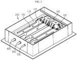
- FIG. 2 is a diagram illustrating the battery pack of the battery rack of FIG. 1
- FIG. 3 is a bottom view of the battery pack of FIG. 2 .
- the battery pack 100 may include a battery cell 110, a pack case 130 and a service plug 150.
- the battery cell 110 may include a secondary battery, for example, a pouch type secondary battery, a prismatic secondary battery or a cylindrical secondary battery.
- a secondary battery for example, a pouch type secondary battery, a prismatic secondary battery or a cylindrical secondary battery.
- this embodiment is described by taking a secondary battery, to be exact, a pouch type secondary battery, as an example of the battery cell 110.
- One or more battery cells 110 may be included. Hereinafter, this embodiment is described based on the plurality of battery cells 110 electrically connected to each other to form a battery cell assembly.
- the pack case 130 may accommodate the plurality of battery cells 110 and different types of electrical components and a cooling unit of the battery pack 100. To this end, the pack case 130 may have an accommodation space in which the components of the battery pack 100 are received.
- the service plug 150 is configured to disconnect the electrical connection of the battery pack 100 by the user manipulation to prevent electric shock accidents in the operator's inspection or management of the battery pack 100, and may be mounted in the pack case 130 and electrically connected to the battery cells 110 or the electrical components of the battery pack 100. Specifically, the service plug 150 may be disposed on the pack case 130 to allow the user or the operator to easily manipulate.
- the battery pack 100 may have at least one coolant injection hole 170 for directly injecting a coolant C (see FIG. 8 ) into the at least one battery pack 100 when injecting the coolant into the battery pack frame 200.
- a plurality of coolant injection holes 170 may be included.
- the plurality of coolant injection holes 170 may be disposed in at least one of the upper surface or the lower surface of the battery pack 100, to be specific, the pack case 130.
- the plurality of coolant injection holes 170 may be disposed in each of the upper surface and the lower surface of the battery pack 100, to be specific, the pack case 130. More specifically, the battery pack 100 may be disposed in the battery pack frame 200, and may be spaced a predetermined distance apart from the inner lower surface of the battery pack frame 200 to smoothly feed the coolant C (see FIG. 8 ) into the battery pack 100 from the bottom of the battery pack 100.
- the at least one battery pack frame 200 may accommodate the at least one battery pack 100 used for the predetermined period of time or below the predetermined capacity, and may have a larger height than the at least one battery pack 100.
- the at least one battery pack frame 200 may be filled with the coolant C (see FIG. 8 ) such that a predetermined height of the at least one battery pack 100 is submerged in the coolant C.
- the at least one battery pack frame 200 may receive the at least one battery pack 100 used for the predetermined period of time or below the predetermined capacity more stably and control a dangerous situation such as a fire more quickly through the coolant C filled inside when the dangerous situation such as the fire occurs due to the abnormal situation caused by the overheat of the at least one battery pack 100.
- a plurality of battery pack frame 200 may be included, and the plurality of battery pack frames 200 may be stacked on top of each other along the heightwise direction of the battery rack 10.
- the at least one battery pack frame 200 will be described in more detail.
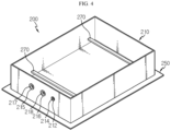
- FIG. 4 is a diagram illustrating the battery pack frame of the battery rack of FIG. 1 .
- the battery pack frame 200 may have an accommodation space which is exposed to top, and the at least one battery pack 100 may be received in the accommodation space.
- At least one feed pipe 400 for feeding the coolant C (see FIG. 7 ) may be disposed above the battery pack frame 200.
- the at least one feed pipe 400 will be described in more detail below.
- At least one smoke detection sensor 500 may be disposed at the upper part of the battery pack frame 200 to detect smoke when the abnormal situation occurs due to overheat of the at least one battery pack 100.
- the at least one smoke detection sensor 500 will be described in more detail below.
- a sensor support 600 on which the at least one smoke detection sensor 500 may be disposed at the upper part of the battery pack frame 200 to support the at least one smoke detection sensor 500.
- the sensor support 600 will be described in more detail below.
- the battery pack frame 200 may include a water tank frame 210 and a support frame 250.
- the water tank frame 210 may have an accommodation space which is exposed to top, for receiving the at least one battery pack 100, and the accommodation space may be filled with the coolant C (see FIG. 8 ).
- the water tank frame 210 may include at least one cable through-hole portion 212, at least one cable sealing member 214, a cooling inlet through-hole portion 215, a cooling outlet through-hole portion 216, an inlet sealing member 217 and an outlet sealing member 218.
- the at least one cable through-hole portion 212 may be disposed on one side of the battery pack frame 200, to be specific, one side of the water tank frame 210, and may allow at least one cable 700 for electrical connection to the at least one battery pack 100 to pass through.
- the at least one cable sealing member 214 is configured to prevent the leakage of the coolant C through the at least one cable through-hole portion 212, and may be mounted in the at least one cable through-hole portion 212.
- the at least one cable sealing member 214 may be mounted in the at least one cable through-hole portion 212.
- the at least one cable sealing member 214 may prevent the leakage of the coolant C from the water tank frame 210 through the cable through-hole portion 212.
- the cooling inlet through-hole portion 215 may be disposed on one side of the battery pack frame 200, to be specific, one side of the water tank frame 210, and may allow a cooling inlet 800 for cooling of the battery pack 100 to pass through.
- the cooling outlet through-hole portion 216 may be disposed on one side of the battery pack frame 200, to be specific, one side of the water tank frame 210, and may allow a cooling outlet 900 for cooling of the battery pack 100 to pass through.
- the inlet sealing member 217 may be mounted in the cooling inlet through-hole portion 215. When the water tank frame 210 is filled with the coolant C (see FIG. 8 ), the inlet sealing member 217 may prevent the leakage of the coolant C from the water tank frame 210 through the cooling inlet through-hole portion 215.
- the outlet sealing member 218 may be mounted in the cooling outlet through-hole portion 216. When the water tank frame 210 is filled with the coolant C (see FIG. 8 ), the outlet sealing member 218 may prevent the leakage of the coolant C from the water tank frame 210 through the cooling outlet through-hole portion 216.
- the support frame 250 may be disposed below the water tank frame 210, and its edge may extend outward from the bottom edge of the water tank frame 210. That is, the support frame 250 may have a wider area than the bottom area of the water tank frame 210.
- the support frame 250 may ensure the strength of the battery pack frame 200. Furthermore, the support frame 250 may prevent the entry of the coolant C into the water tank frame 210 of the adjacent battery pack frame 200 when the coolant C (see FIG. 9 ) flows over the water tank frame 210.
- At least one pack support 270 may be disposed on the inner surface of the battery pack frame 200 to support the battery pack 100 at a predetermined distance H (see FIG. 8 ) apart from the inner lower surface of the battery pack frame 200, that is, the bottom surface of the water tank frame 210. This embodiment is described based on a pair of pack supports 270.
- the pair of pack supports 270 places the bottom surface of the battery pack 100 at the predetermined height H (see FIG. 8 ) apart from the inner lower surface of the battery pack frame 200, that is, the bottom surface of the water tank frame 210 when the battery pack 100 is received in the battery pack frame 200, to guide the effective injection of the coolant C (see FIG. 8 ) into the battery pack 100 from the bottom surface of the battery pack 100.
- FIG. 5 is a diagram illustrating a support frame according to another embodiment of the battery pack frame of FIG. 4 .
- the battery pack frame 205 may include a water tank frame 210 and a support frame 255.
- the water tank frame 210 is substantially identical or similar to the previous embodiment, and an overlapping description is omitted.
- the support frame 255 may have a step portion 257 having a predetermined height at its edge to prevent the coolant C from flowing down when the coolant C (see FIG. 10 ) leaks from the water tank frame 210.
- an additional coolant accommodation space may be formed at the edge of the support frame 255 to further accommodate the coolant C to the predetermined height.
- a drain pipe may be connected to one side of the additional coolant accommodation space at the edge of the support frame 255 to drain the coolant C.
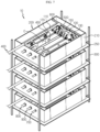
- FIG. 6 is a diagram illustrating the main parts of the battery rack of FIG. 1 .
- the battery rack 10 may further include a rack frame 300, the feed pipe 400, the smoke detection sensor 500, the sensor support 600, the at least one cable 700, the cooling inlet 800 and the cooling outlet 900.
- the rack frame 300 may support the plurality of battery pack frames 200 and guide the vertical stack of the plurality of battery pack frames 200.
- a plurality of feed pipes 400 may be included, and may be disposed above each battery pack frame 200.
- the feed pipes 400 may be connected to a coolant tank (not shown) outside of the battery rack 10.
- Each feed pipe 400 may include at least one spring cooler 450 to spray the coolant C (see FIG. 7 ) onto the at least one battery pack 100.
- the at least one spring cooler 450 may disposed above the battery pack 100 above the battery pack frame 200.
- One or more spring coolers 450 may be included. Hereinafter, this embodiment is described based on the plurality of spring coolers 450.
- the smoke detection sensor 500 may detect smoke coming out of the battery pack 100 to detect a fire when the fire occurred due to overheat of the battery pack 100.
- the smoke detection sensor 500 may be disposed above the service plug 150 of the battery pack 100 where smoke is highly likely to first come out of the battery pack 100.
- the sensor support 600 is configured to support the smoke detection sensor 500 more stably, and may have a bar shape having a predetermined length and may be mounted in the water tank frame 210 of the battery pack frame 200.
- the at least one cable 700 is used to connect the electrical components inside of the battery pack 100 to an external electrical unit, and may be connected to the battery pack 100.
- the at least one cable 700 may be connected to the battery pack 100 in the water tank frame 210 through the cable through-hole portion 212 of the water tank frame 210 of the battery pack frame 200.
- the at least one cable 700 may have a waterproof sealing coating on the outer surface to prevent an electrical short when the water tank frame 210 is filled with the coolant C (see FIG. 8 ).
- the cooling inlet 800 is used to cool the battery pack 100, and may connect an external cooling unit to the battery pack 100.
- the cooling inlet 800 may be connected to the battery pack 100 in the water tank frame 210 through the cooling inlet through-hole portion 215 of the water tank frame 210.
- the cooling outlet 900 is used to cool the battery pack 100, and may connect the external cooling unit to the battery pack 100.
- the cooling outlet 900 may be connected to the battery pack 100 in the water tank frame 210 through the cooling outlet through-hole portion 216 of the water tank frame 210.
- FIGS. 7 and 8 are diagrams illustrating the coolant feed mechanism for preventing the spread of the fire in the event of the abnormal situation caused by overheat of the battery pack of the battery rack of FIG. 1 .
- the abnormal situation may occur in at least one specific battery pack 100. Since the battery pack 100 is the reuse battery pack 100 used for the predetermined period of time or below the predetermined capacity, the abnormal situation may occur due to overheat, causing a fire.
- the smoke detection sensor 500 may detect the smoke, thereby detecting the abnormal situation quickly.
- the coolant C may be quickly sprayed onto the battery pack 100 in which the abnormal situation occurred from the spring coolers 450 of the feed pipe 400 above the battery pack 100 in which the abnormal situation occurred.
- the spray of the coolant C through the spring coolers 450 may continue until the battery pack 100 is submerged in the coolant C in the water tank frame 210 of the battery pack frame 200 to completely put out the fire in the battery pack 100.
- the coolant C may be directly fed into the pack case 130 of the battery pack 100 through the plurality of coolant injection holes 170. Accordingly, in this embodiment, since the coolant C is directly injected into the battery pack 100 in which the abnormal situation occurred, it is possible to put out the fire in the battery pack 100 in which the abnormal situation occurred more quickly.
- the bottom of the battery pack 100 is spaced the predetermined height H apart from the battery pack frame 200, it is possible to feed the coolant C into the pack case 130 more effectively through the coolant injection holes 170 on the bottom of the battery pack 100.
- FIGS. 9 and 10 are diagrams illustrating the mechanism for preventing the entry of the coolant into the underlying battery pack below the battery pack in which the abnormal situation occurred when feeding the coolant in FIG. 8 .
- the coolant C may flow over the water tank frame 210 of the battery pack frame 200.
- the support frame 250 of the battery pack frame 200 extends outward from the water tank frame 210, it is possible to prevent the coolant C from entering the adjacent battery pack 100, to be specific, the underlying battery pack 100 when the coolant C flows over the water tank frame 210.
- the coolant C may be further held in the internal space formed by the step portion 257 when that the coolant C flows over the water tank frame 210.
- the coolant C is further held in the internal space through the step portion 257 to the predetermined height when the coolant C flows over the water tank frame 210, it is possible to further delay the time when the overflowing coolant C pours down. Furthermore, it is possible to prevent the coolant C from flowing down more effectively by stopping the spray of the coolant C from the spring coolers 450 for the delayed time.
- an additional drain pipe may be connected to the internal space formed by the step portion 257, and in this instance, the coolant C may exit through the additional drain pipe, so it is possible to prevent the entry of the coolant C into the underlying battery pack 100 more effectively.
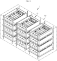
- FIG. 11 is a diagram illustrating an energy storage system according to an embodiment of the present disclosure.
- the energy storage system 1 may include at least one battery rack 10 of the previous embodiment and a rack container 50 accommodating the at least one battery rack 10.
- One or more battery racks 10 may be included. Hereinafter, this embodiment is described based on the plurality of battery racks 10.
- the plurality of battery racks 10 may include a combination of the battery racks 10 including the battery packs 100 used for the predetermined period of time or below the predetermined capacity and battery racks including the general battery packs.
- the rack container 50 may be configured to accommodate the plurality of battery racks 10, and may have an accommodation space in which the plurality of battery racks 10 is received.
- the energy storage system 1 may include the battery packs 100 (see FIG. 1 ) used for the predetermined period of time or below the predetermined capacity or the battery packs 100 used in electric vehicles or hybrid electric vehicles.
- the energy storage system 1 since the energy storage system 1 according to this embodiment includes the battery packs 100 used in vehicles that are usually discarded after wasted, it is possible to achieve cost savings associated with resource recycling and solve the environmental pollution problem caused by the wasted battery packs 100.
- the battery rack 200 for receiving the battery pack 100 for reuse after the use for the predetermined period of time or below the predetermined capacity more stably and ensuring safety when a fire occurs due to an abnormal situation such as overheat, and the energy storage system 1 including the same.
Landscapes
- Chemical Kinetics & Catalysis (AREA)
- Electrochemistry (AREA)
- General Chemical & Material Sciences (AREA)
- Chemical & Material Sciences (AREA)
- Engineering & Computer Science (AREA)
- Manufacturing & Machinery (AREA)
- Business, Economics & Management (AREA)
- Emergency Management (AREA)
- Public Health (AREA)
- Health & Medical Sciences (AREA)
- Aviation & Aerospace Engineering (AREA)
- Battery Mounting, Suspending (AREA)
- Secondary Cells (AREA)
Applications Claiming Priority (2)
| Application Number | Priority Date | Filing Date | Title |
|---|---|---|---|
| KR1020210093531A KR102808526B1 (ko) | 2021-07-16 | 2021-07-16 | 배터리 랙 및 이를 포함하는 전력 저장 장치 |
| PCT/KR2022/010317 WO2023287233A1 (ko) | 2021-07-16 | 2022-07-14 | 배터리 랙 및 이를 포함하는 전력 저장 장치 |
Publications (2)
| Publication Number | Publication Date |
|---|---|
| EP4250455A1 true EP4250455A1 (de) | 2023-09-27 |
| EP4250455A4 EP4250455A4 (de) | 2025-07-09 |
Family
ID=84920290
Family Applications (1)
| Application Number | Title | Priority Date | Filing Date |
|---|---|---|---|
| EP22842495.8A Pending EP4250455A4 (de) | 2021-07-16 | 2022-07-14 | Batteriegestell und energiespeichersystem damit |
Country Status (6)
| Country | Link |
|---|---|
| US (1) | US20230361401A1 (de) |
| EP (1) | EP4250455A4 (de) |
| JP (1) | JP7607768B2 (de) |
| KR (1) | KR102808526B1 (de) |
| CN (1) | CN116391288A (de) |
| WO (1) | WO2023287233A1 (de) |
Family Cites Families (27)
| Publication number | Priority date | Publication date | Assignee | Title |
|---|---|---|---|---|
| KR101075283B1 (ko) * | 2009-02-26 | 2011-10-19 | 에스비리모티브 주식회사 | 이차 전지 모듈 및 그 제조 방법 |
| JP5760713B2 (ja) * | 2011-06-03 | 2015-08-12 | トヨタ自動車株式会社 | 電池パック |
| US20170043194A1 (en) * | 2012-04-10 | 2017-02-16 | Greg Ling | Integrated thermal event suppression system |
| US9379419B2 (en) * | 2013-05-13 | 2016-06-28 | The Boeing Company | Active thermal management and thermal runaway prevention for high energy density lithium ion battery packs |
| JP6279502B2 (ja) * | 2015-03-13 | 2018-02-14 | 株式会社東芝 | 電池モジュール |
| KR102172515B1 (ko) * | 2016-03-16 | 2020-10-30 | 주식회사 엘지화학 | 배터리 모듈 |
| KR102061745B1 (ko) * | 2016-04-25 | 2020-01-02 | 주식회사 엘지화학 | 배터리 팩 및 이러한 배터리 팩을 포함하는 자동차 |
| KR102220902B1 (ko) * | 2017-01-26 | 2021-02-26 | 삼성에스디아이 주식회사 | 소화시스템을 포함하는 배터리 팩 |
| JP2019029245A (ja) * | 2017-08-01 | 2019-02-21 | 株式会社Gsユアサ | 蓄電装置 |
| CN207409535U (zh) * | 2017-08-21 | 2018-05-25 | 上海伊控动力系统有限公司 | 一种用于电动叉车电池舱的结构 |
| KR102468383B1 (ko) * | 2017-09-28 | 2022-11-21 | 현대자동차주식회사 | 차량의 배터리 냉각장치 |
| CN207183380U (zh) * | 2017-09-30 | 2018-04-03 | 重庆聚陆新能源有限公司 | 一种保证消防安全的电池模组集中式仓储与充放电箱体系统 |
| CN107658512A (zh) * | 2017-10-13 | 2018-02-02 | 重庆聚陆新能源有限公司 | 一种灌液式消防的电池模组仓储与充放电箱体系统 |
| US10991923B2 (en) * | 2018-04-13 | 2021-04-27 | GelTech Solutions, Inc. | Lithium ion battery suppression system |
| WO2019207852A1 (ja) * | 2018-04-23 | 2019-10-31 | パナソニックIpマネジメント株式会社 | データセンタのバックアップ用電源システム、バックアップ用電池ラック |
| TWI690350B (zh) * | 2018-10-01 | 2020-04-11 | 協同能源科技股份有限公司 | 淹浸式電池滅火系統及其方法 |
| WO2020152858A1 (ja) * | 2019-01-25 | 2020-07-30 | 株式会社 東芝 | 電池パック及び電池システム |
| KR102381692B1 (ko) * | 2019-02-21 | 2022-03-31 | 주식회사 엘지에너지솔루션 | 배터리 랙 및 이를 포함하는 전력 저장 장치 |
| CN210331433U (zh) * | 2019-03-22 | 2020-04-17 | 中国电力科学研究院有限公司 | 一种具有消防结构的储能电池簇 |
| KR102031645B1 (ko) * | 2019-06-02 | 2019-10-14 | 주식회사 스탠더드시험연구소 | 에너지저장장치 화재예방을 위한 액침식 열제어장치 및 그 운전방법 |
| US11094977B2 (en) * | 2019-08-30 | 2021-08-17 | Baidu Usa Llc | Battery thermal management system with passive battery pack cooling |
| KR102775084B1 (ko) * | 2019-09-19 | 2025-02-27 | 주식회사 엘지에너지솔루션 | 소화 유닛을 포함한 배터리 팩 |
| ES3007207T3 (en) * | 2019-11-08 | 2025-03-19 | Lg Energy Solution Ltd | Battery module, battery rack comprising same, and power storage device |
| CN114450844B (zh) * | 2019-11-08 | 2025-01-10 | 株式会社Lg新能源 | 电池架和包括该电池架的能量存储设备 |
| JP7234912B2 (ja) * | 2019-12-02 | 2023-03-08 | 株式会社デンソー | 電池パック |
| CN111211592A (zh) * | 2019-12-05 | 2020-05-29 | 扬州万锂德能源科技有限公司 | 一种热失控状态下的安全防火锂电充电柜 |
| KR102818037B1 (ko) | 2020-01-20 | 2025-06-10 | 에스케이하이닉스 주식회사 | 응용 프로세서와 데이터를 제공하는 데이터 저장 장치를 포함하는 시스템 |
-
2021
- 2021-07-16 KR KR1020210093531A patent/KR102808526B1/ko active Active
-
2022
- 2022-07-14 EP EP22842495.8A patent/EP4250455A4/de active Pending
- 2022-07-14 WO PCT/KR2022/010317 patent/WO2023287233A1/ko not_active Ceased
- 2022-07-14 US US18/029,335 patent/US20230361401A1/en active Pending
- 2022-07-14 JP JP2023530908A patent/JP7607768B2/ja active Active
- 2022-07-14 CN CN202280007027.6A patent/CN116391288A/zh active Pending
Also Published As
| Publication number | Publication date |
|---|---|
| EP4250455A4 (de) | 2025-07-09 |
| JP2023550629A (ja) | 2023-12-04 |
| KR102808526B1 (ko) | 2025-05-14 |
| JP7607768B2 (ja) | 2024-12-27 |
| WO2023287233A1 (ko) | 2023-01-19 |
| KR20230012806A (ko) | 2023-01-26 |
| US20230361401A1 (en) | 2023-11-09 |
| CN116391288A (zh) | 2023-07-04 |
Similar Documents
| Publication | Publication Date | Title |
|---|---|---|
| US12431570B2 (en) | Battery module having partition wall and thermal insulation layer for fire inhibition | |
| EP3340338B1 (de) | Batteriemodul | |
| EP3279970B1 (de) | Batteriepack | |
| US11489213B2 (en) | Power supply device and vehicle equipped with same | |
| EP4002551B1 (de) | Batterierack und stromspeichervorrichtung damit | |
| US12308467B2 (en) | Battery module including coolant jet spray nozzles with different melting point metal valves, and battery pack and vehicle including same | |
| US20240213576A1 (en) | Battery module and battery pack comprising the same | |
| EP4195387A1 (de) | Batteriepackrahmen und batteriegestell und energiespeichersystem damit | |
| JP2023510899A (ja) | バッテリーパック、それを含む自動車 | |
| EP4303992A1 (de) | Batteriegestell und energiespeichersystem mit batteriegestell | |
| EP4175021B1 (de) | Batteriepack und automobil damit | |
| JP7379720B2 (ja) | バッテリーパック及びそれを含む自動車 | |
| EP4250455A1 (de) | Batteriegestell und energiespeichersystem damit | |
| EP4618253A1 (de) | Batteriepack mit zündverzögerungsstruktur | |
| KR102821428B1 (ko) | 공냉식 배터리 팩 및 배터리를 냉각하는 방법 | |
| KR20250139997A (ko) | 배터리 소화 시스템 | |
| KR20250113705A (ko) | 배터리 팩 소화 시스템 | |
| KR20230155259A (ko) | 배터리 랙 및 이를 포함하는 전력 저장 장치 |
Legal Events
| Date | Code | Title | Description |
|---|---|---|---|
| STAA | Information on the status of an ep patent application or granted ep patent |
Free format text: STATUS: THE INTERNATIONAL PUBLICATION HAS BEEN MADE |
|
| PUAI | Public reference made under article 153(3) epc to a published international application that has entered the european phase |
Free format text: ORIGINAL CODE: 0009012 |
|
| STAA | Information on the status of an ep patent application or granted ep patent |
Free format text: STATUS: REQUEST FOR EXAMINATION WAS MADE |
|
| 17P | Request for examination filed |
Effective date: 20230619 |
|
| AK | Designated contracting states |
Kind code of ref document: A1 Designated state(s): AL AT BE BG CH CY CZ DE DK EE ES FI FR GB GR HR HU IE IS IT LI LT LU LV MC MK MT NL NO PL PT RO RS SE SI SK SM TR |
|
| DAV | Request for validation of the european patent (deleted) | ||
| DAX | Request for extension of the european patent (deleted) | ||
| A4 | Supplementary search report drawn up and despatched |
Effective date: 20250605 |
|
| RIC1 | Information provided on ipc code assigned before grant |
Ipc: H01M 50/204 20210101ALI20250530BHEP Ipc: A62C 35/58 20060101ALI20250530BHEP Ipc: A62C 99/00 20100101ALI20250530BHEP Ipc: A62C 3/16 20060101ALI20250530BHEP Ipc: H01M 10/48 20060101ALI20250530BHEP Ipc: H01M 10/613 20140101ALI20250530BHEP Ipc: H01M 10/627 20140101ALI20250530BHEP Ipc: H01M 10/6567 20140101ALI20250530BHEP Ipc: H01M 50/251 20210101AFI20250530BHEP |
|
| STAA | Information on the status of an ep patent application or granted ep patent |
Free format text: STATUS: EXAMINATION IS IN PROGRESS |
|
| 17Q | First examination report despatched |
Effective date: 20251015 |