EP4250624A2 - Procédé et appareil de communication faisant appel à une formation de faisceau dans un système de communication sans fil - Google Patents
Procédé et appareil de communication faisant appel à une formation de faisceau dans un système de communication sans fil Download PDFInfo
- Publication number
- EP4250624A2 EP4250624A2 EP23191406.0A EP23191406A EP4250624A2 EP 4250624 A2 EP4250624 A2 EP 4250624A2 EP 23191406 A EP23191406 A EP 23191406A EP 4250624 A2 EP4250624 A2 EP 4250624A2
- Authority
- EP
- European Patent Office
- Prior art keywords
- pdcch
- monitoring
- pdcch candidate
- coreset
- candidate
- Prior art date
- Legal status (The legal status is an assumption and is not a legal conclusion. Google has not performed a legal analysis and makes no representation as to the accuracy of the status listed.)
- Granted
Links
Images




Classifications
-
- H—ELECTRICITY
- H04—ELECTRIC COMMUNICATION TECHNIQUE
- H04W—WIRELESS COMMUNICATION NETWORKS
- H04W72/00—Local resource management
- H04W72/20—Control channels or signalling for resource management
- H04W72/23—Control channels or signalling for resource management in the downlink direction of a wireless link, i.e. towards a terminal
- H04W72/231—Control channels or signalling for resource management in the downlink direction of a wireless link, i.e. towards a terminal the control data signalling from the layers above the physical layer, e.g. RRC or MAC-CE signalling
-
- H—ELECTRICITY
- H04—ELECTRIC COMMUNICATION TECHNIQUE
- H04W—WIRELESS COMMUNICATION NETWORKS
- H04W72/00—Local resource management
- H04W72/12—Wireless traffic scheduling
- H04W72/1263—Mapping of traffic onto schedule, e.g. scheduled allocation or multiplexing of flows
- H04W72/1273—Mapping of traffic onto schedule, e.g. scheduled allocation or multiplexing of flows of downlink data flows
-
- H—ELECTRICITY
- H04—ELECTRIC COMMUNICATION TECHNIQUE
- H04B—TRANSMISSION
- H04B7/00—Radio transmission systems, i.e. using radiation field
- H04B7/02—Diversity systems; Multi-antenna system, i.e. transmission or reception using multiple antennas
- H04B7/04—Diversity systems; Multi-antenna system, i.e. transmission or reception using multiple antennas using two or more spaced independent antennas
- H04B7/0408—Diversity systems; Multi-antenna system, i.e. transmission or reception using multiple antennas using two or more spaced independent antennas using two or more beams, i.e. beam diversity
-
- H—ELECTRICITY
- H04—ELECTRIC COMMUNICATION TECHNIQUE
- H04B—TRANSMISSION
- H04B7/00—Radio transmission systems, i.e. using radiation field
- H04B7/02—Diversity systems; Multi-antenna system, i.e. transmission or reception using multiple antennas
- H04B7/04—Diversity systems; Multi-antenna system, i.e. transmission or reception using multiple antennas using two or more spaced independent antennas
- H04B7/08—Diversity systems; Multi-antenna system, i.e. transmission or reception using multiple antennas using two or more spaced independent antennas at the receiving station
- H04B7/0868—Hybrid systems, i.e. switching and combining
- H04B7/088—Hybrid systems, i.e. switching and combining using beam selection
-
- H—ELECTRICITY
- H04—ELECTRIC COMMUNICATION TECHNIQUE
- H04L—TRANSMISSION OF DIGITAL INFORMATION, e.g. TELEGRAPHIC COMMUNICATION
- H04L5/00—Arrangements affording multiple use of the transmission path
- H04L5/0001—Arrangements for dividing the transmission path
- H04L5/0014—Three-dimensional division
- H04L5/0023—Time-frequency-space
-
- H—ELECTRICITY
- H04—ELECTRIC COMMUNICATION TECHNIQUE
- H04L—TRANSMISSION OF DIGITAL INFORMATION, e.g. TELEGRAPHIC COMMUNICATION
- H04L5/00—Arrangements affording multiple use of the transmission path
- H04L5/003—Arrangements for allocating sub-channels of the transmission path
- H04L5/0053—Allocation of signalling, i.e. of overhead other than pilot signals
-
- H—ELECTRICITY
- H04—ELECTRIC COMMUNICATION TECHNIQUE
- H04L—TRANSMISSION OF DIGITAL INFORMATION, e.g. TELEGRAPHIC COMMUNICATION
- H04L5/00—Arrangements affording multiple use of the transmission path
- H04L5/0091—Signalling for the administration of the divided path, e.g. signalling of configuration information
-
- H—ELECTRICITY
- H04—ELECTRIC COMMUNICATION TECHNIQUE
- H04W—WIRELESS COMMUNICATION NETWORKS
- H04W16/00—Network planning, e.g. coverage or traffic planning tools; Network deployment, e.g. resource partitioning or cells structures
- H04W16/24—Cell structures
- H04W16/28—Cell structures using beam steering
-
- H—ELECTRICITY
- H04—ELECTRIC COMMUNICATION TECHNIQUE
- H04W—WIRELESS COMMUNICATION NETWORKS
- H04W72/00—Local resource management
- H04W72/02—Selection of wireless resources by user or terminal
-
- H—ELECTRICITY
- H04—ELECTRIC COMMUNICATION TECHNIQUE
- H04W—WIRELESS COMMUNICATION NETWORKS
- H04W72/00—Local resource management
- H04W72/04—Wireless resource allocation
- H04W72/044—Wireless resource allocation based on the type of the allocated resource
- H04W72/046—Wireless resource allocation based on the type of the allocated resource the resource being in the space domain, e.g. beams
-
- H—ELECTRICITY
- H04—ELECTRIC COMMUNICATION TECHNIQUE
- H04W—WIRELESS COMMUNICATION NETWORKS
- H04W72/00—Local resource management
- H04W72/04—Wireless resource allocation
- H04W72/11—Semi-persistent scheduling
-
- H—ELECTRICITY
- H04—ELECTRIC COMMUNICATION TECHNIQUE
- H04W—WIRELESS COMMUNICATION NETWORKS
- H04W72/00—Local resource management
- H04W72/20—Control channels or signalling for resource management
- H04W72/23—Control channels or signalling for resource management in the downlink direction of a wireless link, i.e. towards a terminal
Definitions
- the disclosure relates to 5G wireless communication (or next-generation wireless communication) and, more particularly, to communication between a user equipment and a base station in a wireless communication system to which beamforming is applied.
- the 5G communication system or pre-5G communication system is called a beyond 4G network communication system or a post LTE system.
- an implementation of the 5G communication system in a mmWave band (e.g., 60 GHz band) is taken into consideration.
- a mmWave band e.g., 60 GHz band
- beamforming, massive MIMO, full dimensional MIMO (FD-MIMO), an array antenna, analog beamforming and large scale antenna technologies are being discussed in the 5G communication system.
- technologies such as an improved small cell, an advanced small cell, a cloud radio access network (cloud RAN), an ultra-dense network, device to device communication (D2D), wireless backhaul, a moving network, cooperative communication, coordinated multi-points (CoMP), and reception interference cancellation, are being developed in the 5G communication system.
- cloud RAN cloud radio access network
- D2D device to device communication
- wireless backhaul a moving network
- cooperative communication coordinated multi-points (CoMP), and reception interference cancellation
- hybrid FSK and QAM modulation and sliding window superposition coding (SWSC) that are advanced coding modulation (ACM) schemes
- ACM advanced coding modulation
- SWSC sliding window superposition coding
- FBMC filter bank multi-carrier
- NOMA non-orthogonal multiple access
- SCMA sparse code multiple access
- the Internet evolves from a human-centered connection network over which human generates and consumes information to Internet of Things (IoT) through which information is exchanged and processed between distributed elements, such as things.
- IoT Internet of Things
- An Internet of Everything (IoE) technology in which a big data processing technology through a connection with a cloud server is combined with the IoT technology is emerging.
- technical elements such as the sensing technology, wired/wireless communication and network infrastructure, service interface technology and security technology, are required. Accordingly, technologies, such as a sensor network, machine to machine (M2M) and machine type communication (MTC) for a connection between things, are recently researched.
- M2M machine to machine
- MTC machine type communication
- an intelligent Internet technology (IT) service in which a new value is created for human life by collecting and analyzing data generated from connected things may be provided.
- the IoT may be applied to fields, such as a smart home, a smart building, a smart city, a smart car or a connected car, a smart grid, health care, smart home appliances, and advanced medical services, through convergence and composition between the existing information technology (IT) and various industries.
- 5G communication technologies such as a sensor network, machine to machine (M2M) and machine type communication (MTC) are implemented by schemes, such as beamforming, MIMO, and an array antenna.
- M2M machine to machine
- MTC machine type communication
- cloud RAN cloud radio access network
- a user equipment may perform communication with a base station through a plurality of beams. Accordingly, various discussions take place in order for transmission and reception using beamforming to be smoothly performed.
- the disclosure proposes a method and apparatus for smoothly transmitting and receiving control information through a control channel between a user equipment and a base station in a communication environment using beamforming.
- Technical objects to be achieved in the disclosure are not limited to the aforementioned technical objects, and other technical objects not described above may be considered by a person having ordinary knowledge in the art to which the disclosure pertains from embodiments of the disclosure to be described later.
- a method of a user equipment includes a operation of receiving a downlink signal from a base station using a first beam, an operation of determining whether a downlink control channel is able to be monitored using a second beam, and an operation of skipping the monitoring of the downlink control channel if the downlink control channel is determined to be unable to be monitored using the second beam.
- the operation of determining may include determining that the downlink control channel is unable to be monitored in case that a time interval in which data is received from the downlink signal using the first beam and timing at which the downlink control channel is monitored in the downlink signal using the second beam overlap.
- the data received using the first beam may be data scheduled through a control channel or data configured by semi-persistent scheduling (SPS).
- SPS semi-persistent scheduling
- the operation of determining may include determining that the downlink control channel is unable to be monitored, in case that a time offset up to timing at which the downlink control channel is monitored using the second beam after the reception of the data using the first beam is terminated is less than a threshold value.
- the operation of determining may include determining that the downlink control channel is unable to be monitored, in case that a time offset up to the downlink control monitoring using the second beam after the monitoring of the downlink control channel using the first beam is less than a threshold value.
- the method of the user equipment may further include an operation of selecting a beam for the monitoring of the downlink control channel among the first beam and the second beam and an operation of monitoring the downlink control channel using the selected beam.
- the operation of selecting may include selecting a beam corresponding to a downlink control channel in which a search space set to which the downlink control channel belongs is a common search space, selecting a beam corresponding to a downlink control channel in which an identifier of a control resource set (CORESET) has a small value, selecting a beam corresponding to a downlink control channel first located in a time axis, selecting a beam corresponding to a downlink control channel associated with a specific radio network temporary identifier (RNTI), or selecting a beam corresponding to a downlink control channel indicated by the base station.
- CORESET control resource set
- the operation of determining may include determining that the downlink control channel is able to be monitored in case that the user equipment further may include an antenna array to form the second beam in addition to the antenna array to form the first beam.
- the antenna array is a unit to form one beam
- each of the antenna arrays included in the user equipment may include a plurality of antenna elements.
- the user equipment may monitor the downlink control channel using the second beam.
- each of the first beam and the second beam may be formed to receive a reference signal of a different antenna port.
- a user equipment includes a transceiver transmitting and receiving signals and a controller configured to receive a downlink signal from a base station using a first beam, determine whether a downlink control channel is able to be monitored using a second beam, and skip the monitoring of the downlink control channel if the downlink control channel is determined to be unable to be monitored using the second beam.
- control information can be efficiently transmitted and received according to circumstances because a user equipment operates by considering a parameter configured in the user equipment and a communication environment that is flexibly changed together.
- each of the blocks of the flowchart drawings and combinations of the blocks of the flowchart drawings can be executed by computer program instructions.
- These computer program instructions may be mounted on the processor of a general purpose computer, a special purpose computer or other programmable data processing apparatus, so that the instructions executed by the processor of the computer or other programmable data processing apparatus create means for executing the functions specified in the flowchart block(s).
- These computer program instructions may also be stored in a computer-usable or computer-readable memory that can direct a computer or other programmable data processing equipment to implement function in a particular manner, such that the instructions stored in the computer-usable or computer-readable memory produce an article of manufacture including instruction means that implement the function specified in the flowchart block(s).
- the computer program instructions may also be loaded on a computer or other programmable data processing apparatus to cause a series of operational steps to be performed on the computer or other programmable data processing apparatus to produce a computer-executed process, so that the instructions performing the computer or other programmable data processing apparatus may provide steps for executing the functions described in the flowchart block(s).
- each block of the flowchart drawings may represent a portion of a module, a segment or code, which includes one or more executable instructions for implementing a specified logical function(s). It should also be noted that in some alternative implementations, the functions noted in the blocks may be performed out of order. For example, two blocks shown in succession may in fact be executed substantially concurrently or the blocks may sometimes be executed in the reverse order, depending upon the functionality involved.
- the term "unit”, as used in the present embodiment means software or a hardware component, such as a field programmable gate array (FPGA) or an application-specific integrated circuit (ASIC), and the “unit” performs specific tasks.
- FPGA field programmable gate array
- ASIC application-specific integrated circuit
- the meaning of “-unit” is not limited to software or hardware.
- the “unit” may advantageously be configured to reside on an addressable storage medium and configured to operate on one or more processors.
- the “unit” may include, for example, components, such as software components, object-oriented software components, class components, and task components, processes, functions, attributes, procedures, sub-routines, segments of program code, drivers, firmware, microcode, circuitry, data, databases, data structures, tables, arrays, and variables.
- the functionalities provided in the components and "units” may be combined into fewer components and “units” or may be further separated into additional components and “units.” Furthermore, the components and “units” may be implemented to operate on one or more CPUs within a device or a security multimedia card.
- FIG. 1 is a diagram describing a beam measurement process in a 5G communication environment 100 using beamforming.
- a scheme using an ultra-high frequency band is being discussed in a next-generation communication system.
- a high frequency band used in such a next-generation communication system has a relatively severe path loss. Accordingly, in order to increase the transfer distance of a radio wave, to perform communication using a narrow beam by applying beamforming is being discussed.
- a beam pair link configured with the transmission beam of a transmission stage and the reception beam of a reception stage is used for data transmission and reception between a terminal (or, a user equipment (UE)) and a base station (BS).
- a terminal or, a user equipment (UE)
- BS base station
- beamforming it is important to find out an optimal beam between a UE 104 and a BS 102 because a beam is narrowly formed to have directivity.
- the BS and the UE it is necessary for the BS and the UE to find out an optimal beam to be used for communication and to share information on the optimal beam because a channel environment may be changed from time to time.
- a process of finding out an optimal beam as described above is called a beam measurement process.
- the UE and the BS find out an optimal beam to be used for communication while sweeping (or changing) the transmission beam and the reception beam.
- FIG. 2 is a diagram describing an example 200 of a radio resource for describing a bandwidth part (BWP), a control resource set (CORESET) and a search space set configured in a user equipment.
- BWP bandwidth part
- CORESET control resource set
- search space set configured in a user equipment.
- At least one bandwidth part (BWP) 202 may be configured in a UE that operates in the aforementioned communication system (or 5G communication system) using beamforming.
- the UE performs transmission and reception within only the configured BWP.
- Such a BWP configuration is performed in a UE-specific manner, and a BWP configured in each UE may be independently present within a frequency band supported by a BS.
- a maximum of three control resource sets (CORESETs) 204a, 204b, and 204c may be configured for each BWP.
- a maximum of 10 search space sets may be configured for each BWP.
- the UE may receive downlink data from the BS in a specific radio resource 206 or transmit uplink data to the BS by receiving control information received through a search space set associated with the CORSET.
- the radio resource 206 scheduled by the control information may be located within a slot 210 in which the control information is received, and may be located in another slot 220 in a time axis.
- a UE may receive a parameter for configuring a CORESET, such as Table 1, through radio resource control (RRC) signaling. Furthermore, the UE may receive a parameter for configuring a search space set, such as Table 2, through RRC signaling.
- RRC radio resource control
- a 5G UE may determine whether to monitor a physical downlink control channel (PDCCH) using what beam on what time-frequency resource through signaling for configuring the parameter described in Table 1 and Table 2, and may monitor the PDCCH on a corresponding radio resource.
- PDCCH physical downlink control channel
- the 5G UE may perform an operation for receiving the corresponding PDSCH.
- the UE may perform an operation of determining through which beam the PDSCH is transmitted, and may determine a beam through which the PDSCH is transmitted using a method, such as Table 3 below, for example.
- a transmission configuration indication may mean a specific beam to be used for transmission by a BS.
- the "TCI-presentInDCI” parameter notifies whether TCI information is included in downlink control information (DCI).
- TCI-StatesPDCCH indicates a specific beam to be used by the BS for PDCCH transmission.
- One demodulation reference signal (DMRS) antenna port corresponds to a specific radio resource grid, and thus also corresponds to a transmission beam defined to transmit the DMRS of a pattern defined as a corresponding DMRS antenna port.
- DMRS demodulation reference signal
- the specific DMRS antenna port directly corresponds to a specific transmission beam defined for the reception of the corresponding DMRS, and thus a TCI-state to be described hereinafter may mean a specific transmission beam formed by a BS.
- a UE may previously determine, manage and retain a reception beam associated for each transmission beam of the BS.
- “Threshold-Sched-Offset” that is, a value defined based on performance or the capability of a UE, means a time interval necessary to change a beam formed by the UE. It is meant that a UE having a great "Threshold-Sched-Offset" value requires a relatively longer time in order to change a reception beam, whereas a UE having a small corresponding value may change a reception beam at a shorter interval.
- Such a “Threshold-Sched-Offset” value may be related to a time offset between a PDCCH and a PDSCH indicated by the downlink grant of the PDCCH.
- the UE may determine through which beam the PDSCH is transmitted based on the relation between the PDCCH and the PDSCH (e.g., as in Table 3), and may receive the PDSCH.
- the UE may determine the reception beam of the UE based on the transmission beam.
- the location of a PDCCH candidate(s) in the time axis may be determined through a search space set parameter associated with the CORESET. That is, the reception beam of the UE for PDCCH monitoring may be changed or may not be changed depending on a configuration. If the reception beam of the UE for PDCCH monitoring is configured to be changed, the time for the UE to form a beam for monitoring the PDCCH by changing the reception beam may be sufficient. However, a case where time may not be sufficient in relation to the "Threshold-Sched-Offset" value may occur.
- the reception location of a PDSCH in the time axis may be configured very flexibly and dynamically, such as cross-slot scheduling (a method of scheduling a PDSCH or PUSCH in the slot n+k of a slot n), a slot aggregation (a method of scheduling a PDSCH or PUSCH in m slots), or mini-slot scheduling (method of scheduling some symbols within a slot).
- a reception beam for receiving data in the PDSCH may also be changed from time to time. Since the PDSCH reception timing is dynamically changed as described above, a case where data reception timing and PDCCH monitoring timing through the PDSCH overlap in the time axis may occur.
- beams for the PDSCH reception and the PDCCH monitoring in the time axis may be the same or different. If a UE has to change a reception beam because a configured beam is different, a case where the time for changing the beam is not sufficient may occur.
- FIG. 3 is a diagram describing an operation of a UE in a case where an embodiment of the disclosure is applied.
- FIG. 3 illustrates a process 300 of receiving, by the UE, control information transmitted through a PDCCH from a base station (BS) and receiving data transmitted through a PDSCH on a time-frequency resource.
- control information received by the UE by monitoring a PDCCH 312 schedules the reception of data ion a PDSCH 314 (or although not explicitly illustrated in FIG. 3 , the PDSCH 314 may be received through a semi-persistent scheduling (SPS) configuration).
- SPS semi-persistent scheduling
- the PDSCH 314 scheduled in the UE may overlap another PDCCH 316 to be monitored by the UE in a time axis. That is, the UE monitors the PDCCH based on a CORESET and search space set pre-configured in the UE. A case where the radio resource of a PDSCH scheduled by a specific PDCCH overlaps another PDCCH in the time axis may occur.
- the UE may receive the PDCCHs 312 and 314 and the PDSCH 314 using a common beam 1.
- a CORESET parameter, DCI, etc. may be configured to have the same TCI-state with respect to the PDCCH and the PDSCH or the monitoring timing of all the PDCCHs 312 and 316 in FIG. 3(a) may belong to a search space set mapped to one CORESET.
- the UE does not need to change a beam for receiving the PDSCH 314 and the PDCCH 316. Accordingly, the UE may monitor the PDCCH 316 in another frequency axis while receiving the PDSCH 314.
- FIG. 3(b) there is another PDCCH 326 to be monitored within a time interval in which a UE receives a PDSCH 324 scheduled by a PDCCH 322.
- the UE may monitor the PDCCH 326 while receiving data from the PDSCH 324 without a separate beam change because a beam 1 for monitoring the PDCCH 326 and a beam 1 for receiving the PDSCH 324 are the same.
- FIG. 4 is a diagram describing an operation of a UE in a case where another embodiment of the disclosure is applied.
- an operation of the UE in each of various situations 400 illustrated in FIG. 4 is described.
- FIG. 4(a) timing at which a PDSCH 414 scheduled by a PDCCH 412 is received and timing at which another PDCCH 416 is monitored may overlap in a time axis.
- a beam 1 for receiving the PDSCH 414 and a beam 2 for receiving the PDCCH 416 may be different.
- this corresponds to a case where a CORESET is configured so that a PDCCH and a PDSCH have different TCI-states or a case where a PDSCH beam indicator within downlink control information (DCI) designates a beam different from that of a CORESET to which the PDCCH is mapped with respect to the PDSCH.
- DCI downlink control information
- a UE may skip or omit the monitoring of the PDCCH 416 that overlaps the PDSCH 414 in the time axis. That is, the UE may skip the monitoring of a PDCCH at the monitoring occasion of the PDCCH 416 that overlaps the scheduled PDSCH 414.
- the UE may skip the monitoring of the PDCCH 416.
- the time interval of a PDSCH 424 scheduled by a PDCCH 422 and monitoring timing of a PDCCH 416 may overlap in a time axis. Since a beam 2 for monitoring the PDCCH 426 and a beam 1 for receiving the PDSCH 424 are different, a UE may skip the monitoring of the PDCCH 426 that overlaps the PDSCH 424. For another example, in FIG.
- a UE may skip or omit the monitoring of a PDCCH 432 if a beam for receiving a PDSCH 434 scheduled by the PDCCH 432 is a beam 3 different from the beam of the PDCCH 432 and monitoring timing of a PDCCH 436 (beam 1, that is, the same beam as that of the PDCCH 432) overlaps a time interval in which the PDSCH 432 has been scheduled.
- a beam for receiving a PDSCH 434 scheduled by the PDCCH 432 is a beam 3 different from the beam of the PDCCH 432 and monitoring timing of a PDCCH 436 (beam 1, that is, the same beam as that of the PDCCH 432) overlaps a time interval in which the PDSCH 432 has been scheduled.
- FIG. 5 is a diagram describing an operation of a UE in a case where still another embodiment of the disclosure is applied. Hereinafter, an operation of the UE in a situation 500 illustrated in FIG. 5 is described.
- monitoring timing of another PDCCH 512 may overlap a time interval in which a PDSCH 514 received by a downlink SPS configuration is received.
- FIG. 5 is a diagram describing an operation of a UE in a case where still another embodiment of the disclosure is applied.
- monitoring timing of another PDCCH 512 may overlap a time interval in which a PDSCH 514 received by a downlink SPS configuration is received.
- the UE may skip the monitoring of the PDCCH 512.
- the UE may omit or skip the monitoring of the PDCCH 512 at the monitoring occasion of the PDCCH 512 that overlaps the PDSCH 514 received by a DL SPS configuration.
- FIG. 6 is a flowchart describing an operation of a UE according to an embodiment of the disclosure.
- FIG. 6 illustrates, according to a time-series flow, an operation 600 of the UE according to the embodiment described with reference to FIGS. 3 to 5 .
- the UE 104 identifies that the time interval of a PDSCH scheduled by a PDCCH and monitoring timing of another PDCCH overlap in a time axis (610).
- the UE 104 identifies whether it can monitor a PDCCH using a beam configured to receive a PDSCH (620). If the beam configured to receive the PDSCH and the beam for monitoring the PDCCH are the same (e.g., in the case of FIG. 3 ), the UE 104 (e.g., the terminal controller 1520 and a transceiver 1510) may monitor the PDCCH while receiving the PDSCH (630). In contrast, if the two beams are different, the UE 104 (e.g., the terminal controller 1520 and the transceiver 1510) may receive the PDSCH and skip the monitoring of the PDCCH (640).
- FIG. 7 is a diagram describing an operation of a UE in a case where still another embodiment of the disclosure is applied.
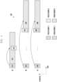
- the UE may receive a PDSCH 714 scheduled by a PDCCH 712, and may monitor another PDCCH 716 after a given time offset.
- the beams of the PDSCH 714 and the PDCCH 716 are different (PDSCH 714: a beam 1, and a PDCCH 716: beam 2), but the PDSCH 714 and the PDCCH 716 do not overlap in a time axis, unlike in the aforementioned embodiments.
- a time offset between monitoring timing of the PDSCH 714 and monitoring timing of the PDCCH 716 is a given threshold value or more (e.g., a value based on "Threshold-Sched-Offset") configured in the UE, that is, if the UE has a sufficient time to change a reception beam, the UE may monitor the PDCCH 716. In contrast, if the corresponding time offset is less than the threshold value, the UE may determine that the time for changing the reception beam is not sufficient and omit or skip the monitoring of the PDCCH 716.
- the UE after receiving a PDSCH 724 (beam 2) scheduled by a PDCCH 722 (beam 1), the UE identifies whether monitoring timing of a PDCCH 726 (beam 1) is reached after a given time. In this case, if the beam for receiving the PDSCH 724 and the beam for monitoring the PDCCH 726 are different and a time offset between the reception termination of the PDSCH 724 and the monitoring timing of the PDCCH 726 is less than a threshold value, the UE may skip the monitoring of the PDCCH 726. Even in the case of FIG. 7(c) , if the time is not sufficient to change a beam for receiving a PDCCH 736, the UE may skip the monitoring of the PDCCH 736.
- FIG. 8 is a diagram describing an operation of a UE in a case where still another embodiment of the disclosure is applied.
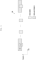
- a PDSCH 814 received by a downlink SPS configuration is configured to be received using a beam 2.
- the UE identifies whether a time offset between the reception of the PDSCH 814 and the monitoring timing of the PDCCH 812 is less than a given threshold value.
- the UE may skip the monitoring of the PDCCH 812.
- the time offset is the threshold value or more, the UE may monitor the PDCCH 812.
- the reason why the UE skips the monitoring of the PDCCH after receiving the PDSCH based on the SPS configuration is that the PDSCH reception based on the SPS configuration has been configured based on a specific intention of a BS.
- FIG. 9 is a diagram describing an operation of a UE in a case where still another embodiment of the disclosure is applied.
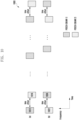
- the UE may be configured to monitor a PDCCH using a plurality of beams.
- a radio resource indicated as 912 belongs to a CORESET #p, and the CORESET #p may be mapped to TCI-state-x.
- a radio resource indicated as 914 belongs to a CORESET #p+1, and the CORESET #p+1 may be mapped to TCI-state-y.
- a time offset between a PDCCH monitoring resource 912 determined by a search space set associated with the CORESET #p and a PDCCH monitoring resource 914 determined by a search space set associated with the CORESET #p+1 may be set at least greater than a specific threshold value (a value based on "Threshold-Sched-Offset" of the UE).
- a specific threshold value a value based on "Threshold-Sched-Offset" of the UE.
- FIG. 10 is a diagram describing an operation of a UE in a case where still another embodiment of the disclosure is applied.
- FIG. 10 illustrates a case where when the UE monitors a PDCCH using a plurality of beams, a time offset between the PDCCH monitoring occasion 1012 or 1024 of a search space set associated with a CORESET #p and the PDCCH monitoring occasions 1014 or 1022 of a search space set associated with a CORESET #p+1 is set to be smaller than a threshold value, unlike in the embodiment of FIG. 9 .
- the UE may not secure a time sufficient to monitor the PDCCH while changing beams in all of the plurality of PDCCH monitoring occasions ( FIGS. 10(a) and 10(b) ).
- the UE may select a TCI-state mapped to the radio resource of a monitoring occasion corresponding to one search space set, among monitoring occasions corresponding to a plurality of search space sets, and may monitor a PDCCH only in the corresponding monitoring occasion.
- a criterion on which a UE selects a specific PDCCH monitoring resource may be various. For example, the UE may select a PDCCH monitoring occasion (or resource) through a combination of one or more of the following criteria.
- FIG. 11 is a flowchart describing an operation of a UE according to another embodiment of the disclosure.
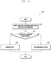
- FIG. 11 illustrates, according to a time-series flow, an operation 1100 of the UE according to the embodiments described with reference to FIGS. 7 to 10 .
- the UE 104 After receiving a PDSCH based on the scheduling of a PDCCH, the UE 104 (e.g., the terminal controller 1520) identifies a time offset between PDSCH reception completion timing and PDCCH monitoring start timing when monitoring timing of another PDCCH is reached (1110). If the measured time offset is a threshold value or more, the UE 104 (e.g., the terminal controller 1520 and the transceiver 1510) changes a beam into a beam for PDCCH monitoring and monitors the PDCCH (1120, 1130). In contrast, if the time offset is less than the threshold value, the UE 104 (e.g., the terminal controller 1520 and the transceiver 1510) may skip the monitoring of the PDCCH (1120, 1140).
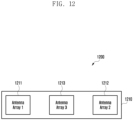
- FIG. 12 is a flowchart describing an antenna configuration of a UE according to another embodiment of the disclosure.
- the antenna configuration 1200 illustrated in FIG. 12 may be an example in which the transceiver 1510 of a UE 1500 is implemented, and may correspond to an example in which the transceiver 1610 of a BS 1600 described based on a UE is implemented.
- the antenna 1210 of the UE may include one or more mmWave antenna arrays 1211, 1212, and 1213.
- Each of the mmWave antenna arrays is a unit that forms one reception beam, and may be configured to include a plurality of antenna elements, such as 4x4 and 1x4.
- a UE including a plurality of antenna arrays may basically communicate with a BS using one antenna array if the TCI-states of CORESETs configured by the BS are the same.
- a UE may operate using one antenna array.
- a PDCCH may skip the monitoring of the PDCCH in some resources as in the aforementioned embodiment.
- the UE may monitor a PDCCH in a different PDCCH monitoring resource using each beam in a different antenna array through a plurality of antenna arrays. In such a case, the UE may not skip the monitoring of a specific PDCCH. If the UE operates using only one of the plurality of antenna arrays and a case, such as FIG. 10 , occurs, the UE may operate in a way to enable another antenna array, if necessary.
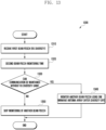
- FIG. 13 is a diagram describing an operation 1300 of a UE according to another embodiment of the disclosure.
- FIG. 13 describes, according to a time-series flow, an example of an operation of the UE including a plurality of mmWave antenna arrays as in FIG. 12 .
- the UE 104 receives a PDSCH using a first beam, while also operating a plurality of antenna arrays (1310). As described above, Rx diversity may occur because the plurality of antenna arrays operates the same beam.
- the UE 104 determines whether communication with the BS 102 can be maintained without a reception (Rx) diversity gain (1330).
- the UE 104 may change the reception beam of one of the operating antenna arrays, and may monitor a PDCCH through the second beam (1340). In such a case, the reception diversity gain no longer occurs.
- the UE 104 may skip the monitoring of a PDCCH using another beam (1350) because the communication with the BS 102 may not be smoothly performed.
- the UE 104 e.g., the terminal controller 1520
- AGC automatic gain control
- the UE 104 When the UE 104 (e.g., the terminal controller 1520 and the transceiver 1510) includes 3 antenna arrays as in FIG. 12 and operates using the antenna array 1 1211 and the antenna array 2 1212 (e.g., multiple-input multiple-output (MIMO), Rx diversity, or a carrier aggregation (CA)), the UE 104 (e.g., the terminal controller 1520 and the transceiver 1510) may monitor a PDCCH using another beam through the antenna array 3 1213.
- MIMO multiple-input multiple-output
- CA carrier aggregation
- the UE 104 may use an AGC value, used in the antenna arrays 1 and 2 and generated through interpolation, for the AGC operation of the antenna array 3 1213.
- the UE 104 (e.g., the terminal controller 1520 and the transceiver 1510) performing communication in a plurality of component carriers may monitor a PDCCH in each of the plurality of component carriers.
- the UE 104 e.g., the terminal controller 1520 and the transceiver 1510 may monitor the PDCCH within the plurality of component carriers using one antenna array.
- the UE 104 e.g., the terminal controller 1520 and the transceiver 1510 may monitor the PDCCH in each of the component carriers using a plurality of antenna arrays.
- the UE 104 may enable and operate only one antenna array. For example, in the case of an intra-frequency CA or if a frequency difference including the bandwidth of each component carrier is within a bandwidth which may be processed by one modem, the UE 104 (e.g., the terminal controller 1520 and the transceiver 1510) may monitor a PDCCH in the plurality of component carriers by enabling one antenna array.
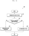
- FIG. 14 is a diagram describing an operation of a UE according to another embodiment of the disclosure. An operation 1400 of the UE according to the aforementioned embodiments is described with reference to FIG. 14 .
- the UE 104 e.g., the terminal controller 1520
- the terminal controller 1520 performing communication using a first beam (1410) determines whether it can monitor a PDCCH using a second beam at PDCCH monitoring timing (1420).
- the UE 104 (e.g., the terminal controller 1520) can monitor the PDCCH using the second beam (e.g., if the first beam and the second beam are the same, time for changing the first beam into the second beam is sufficient, or an antenna array that will form the second beam is present), the UE 104 (e.g., the terminal controller 1520 and the transceiver 1510) monitors the PDCCH using the second beam (1430).
- the UE 104 e.g., the terminal controller 1520 and the transceiver 1510 monitors the PDCCH using the second beam (1430).
- the UE 104 may omit or skip the monitoring of the PDCCH.
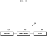
- FIG. 15 is a diagram illustrating a structure 1500 of a UE according to an embodiment of the disclosure.
- the structure 1500 of the UE illustrated in FIG. 15 may be an example of the configuration of the UE 104 described with reference to FIG. 1 .
- the UE may include a transceiver 1510, a terminal controller 1520, and a storage 1530.
- the terminal controller 1520 may be defined as a circuit or an application-specific integrated circuit or at least one processor.
- the transceiver 1510 transmits and receives signals to or from a different network entity.
- the transceiver 1510 may receive a downlink signal for beam measurement from a BS or transmit beam failure-related information to the BS, for example.
- the transceiver 1510 may be implemented in the form of an RF unit including a modem.
- the terminal controller 1520 may control an overall operation of the UE according to an embodiment proposed in the disclosure.
- the terminal controller 1520 may control the transceiver 1510 and the storage 1530 to perform the operations according to the embodiments described with reference to the drawings.
- the terminal controller 1520 may receive, from a BS, a parameter for control information transmitted through a control channel, and may receive control information from a control channel.
- the storage 1530 may store at least one of information transmitted and received through the transceiver 1510 and information generated through the terminal controller 1520.
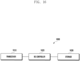
- FIG. 16 is a diagram illustrating a structure of a base station according to an embodiment of the disclosure.
- the structure 1600 of the BS illustrated in FIG. 16 may be an example of the configuration of the BS 102 described with reference to FIG. 1 .
- the BS may include a transceiver 1610, a BS controller 1620, and a storage 1630.
- the BS controller 1620 may be defined as a circuit or an application-specific integrated circuit or at least one processor.
- the transceiver 1610 may transmit and receive signals to or from another network entity.
- the transceiver 1610 may transmit, to a UE, a reference signal for beam measurement, a synchronization signal or a downlink signal, such as a PDCCH, for example.
- the transceiver 1610 may be implemented in the form of an RF unit including a modem.
- the BS controller 1620 may control an overall operation of the BS according to an embodiment proposed in the disclosure.
- the BS controller 1620 may control the transceiver 1610 and the storage 1630 to perform the operations according to the embodiments described in the drawings.
- the BS controller 1620 may transmit configuration information for transmitting control information to a UE, and may transmit control information to a UE through a control channel.
- the storage 1630 may store at least one of information transmitted and receive through the transceiver 1610 and information generated through the BS controller 1620.
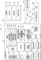
- FIG. 17 is a block diagram of an electronic device 1701 within a network environment 1700 according to various embodiments.
- the electronic device 1701 illustrated in FIG. 17 may be an example of the configuration of the UE 1500 described with reference to FIG. 15 .
- the electronic device 1701 may communicate with an electronic device 1702 over a first network 1798 (e.g., a short-distance wireless communication network) or may communicate with an electronic device 1704 or a server 1708 over a second network 1799 (e.g., a long-distance wireless communication network).
- the electronic device 1701 may communicate with the electronic device 1704 through the server 1708.
- the electronic device 1701 may include a processor 1720, a memory 1730, an input device 1750, a sound output device 1755, a display device 1760, an audio module 1770, a sensor module 1776, an interface 1777, a haptic module 1779, a camera module 1780, a power management module 1788, a battery 1789, a communication module 1790, a subscriber identity module 1796, or an antenna module 1797.
- at least one (e.g., the display device 1760 or the camera module 1780) of the elements may be omitted from the electronic device 1701 or one or more different elements may be added to the electronic device 1701.
- some of the elements may be implemented as one integrated circuit.
- the sensor module 1776 e.g., a fingerprint sensor, an iris sensor, or an illuminance sensor
- the display device 1760 e.g., display
- the processor 1720 may control at least one different element (e.g., hardware or software element) of the electronic device 1701 coupled to the processor 1720 or perform various data processing or operations by executing software (e.g., a program 1740), for example.
- the processor 1720 may load instructions or data, received from another element (e.g., the sensor module 1776 or the communication module 1790), onto a volatile memory 1732, may process the instructions or data stored in the volatile memory 1732, and may store the resulting data in a non-volatile memory 1734.
- the processor 1720 may include a main processor 1721 (e.g., a central processing unit or an application processor) and an auxiliary processor 1723 (e.g., a graphic processor, an image signal processor, a sensor hub processor, or a communication processor) which may operate independently of or together with the main processor 1721. Additionally or alternatively, the auxiliary processor 1723 may be configured to use lower power than the main processor 1721 or to be specified in a designated function. The auxiliary processor 1723 may be implemented separately from or as a part of the main processor 1721.
- a main processor 1721 e.g., a central processing unit or an application processor
- auxiliary processor 1723 e.g., a graphic processor, an image signal processor, a sensor hub processor, or a communication processor
- the auxiliary processor 1723 may be configured to use lower power than the main processor 1721 or to be specified in a designated function.
- the auxiliary processor 1723 may be implemented separately from or as a part of the main processor 1721.
- the auxiliary processor 1723 may control at least some of functions or states related to at least one element (e.g., the display device 1760, the sensor module 1776, or the communication module 1790) of the elements of the electronic device 1701, instead of the main processor 1721 while the main processor 1721 is in an inactive (e.g., sleep) state or along with the main processor 1721 while the main processor 1721 is in an active (e.g., application execution) state, for example.
- the auxiliary processor 1723 e.g., an image signal processor or a communication processor
- the memory 1730 may store various data used by at least one element (e.g., the processor 1720 or the sensor module 1776) of the electronic device 1701.
- the data may include software (e.g., the program 1740) and input data or output data for a related instruction, for example.
- the memory 1730 may include the volatile memory 1732 or the non-volatile memory 1734.
- the program 1740 may be stored in the memory 1730 as software, and may include an operating system 1742, middle ware 1744 or an application 1746, for example.
- the input device 1750 may receive, from the outside (e.g., user) of the electronic device 1701, instructions or data to be used for an element (e.g., processor 1720) of the electronic device 1701.
- the input device 1750 may include a microphone, a mouse, or a keyboard, for example.
- the sound output device 1755 may output a sound signal to the outside of the electronic device 1701.
- the sound output device 1755 may include a speaker or a receiver, for example.
- the speaker may be used for common uses, such as multimedia playback or recording playback.
- the receiver may be used to receive an incoming call. According to an embodiment, the receiver may be implemented separately from or as a part of the speaker.
- the display device 1760 may visually provide information to the outside (e.g., user) of the electronic device 1701.
- the display device 1760 may include a control circuit for controlling a display, a hologram device or a projector and a corresponding device, for example.
- the display device 1760 may include a touch circuitry configured to detect a touch or a sensor circuitry (e.g., a pressure sensor) configured to measure the intensity of a force generated by the touch.
- the audio module 1770 may convert a sound into an electrical signal or may convert an electrical signal into a sound. According to an embodiment, the audio module 1770 may obtain a sound through the input device 1750 or may output a sound through the sound output device 1755 or an external electronic device (e.g., the electronic device 1702) (e.g., a speaker or a headphone)) directly or wirelessly coupled to the electronic device 1701.
- an external electronic device e.g., the electronic device 1702
- the electronic device 1702 e.g., a speaker or a headphone
- the sensor module 1776 may detect an operating state (e.g., power or temperature) of the electronic device 1701 or an external environment state (e.g., user state), and may generate an electrical signal or data value corresponding to the detected state.
- the sensor module 1776 may include a gesture sensor, a gyro sensor, an atmospheric sensor, a magnetic sensor, an acceleration sensor, a grip sensor, a proximity sensor, a color sensor, an infrared (IR) sensor, a bio sensor, a temperature sensor, a humidity sensor, or an illuminance sensor, for example.
- the interface 1777 may support one or more designated protocols which will be used for the electronic device 1701 to be directly or wirelessly coupled to an external electronic device (e.g., the electronic device 1702).
- the interface 1777 may include a high definition multimedia interface (HDMI), a universal serial bus (USB) interface, an SD card interface, or an audio interface, for example.
- HDMI high definition multimedia interface
- USB universal serial bus
- SD card interface Secure Digital Card
- audio interface for example.
- connection terminal 1778 may include a connector through which the electronic device 1701 may be physically coupled to an external electronic device (e.g., the electronic device 1702).
- the connection terminal 1778 may include an HDMI connector, a USB connector, an SD card connector, or an audio connector (e.g., a headphone connector), for example.
- the haptic module 1779 may convert an electrical signal into a mechanical stimulus (e.g., vibration or motion) or an electrical stimulus which may be recognized by a user through a tactile or kinesthetic sense.
- the haptic module 1779 may include a motor, a piezoelectric element, or an electrical stimulus element, for example.
- the camera module 1780 may photograph a still image and a moving image.
- the camera module 1780 may include one or more lenses, image sensors, image signal processors, or flashes.
- the power management module 1788 may manage power supplied to the electronic device 1701.
- the power management module 388 may be implemented as at least part of a power management integrated circuit (PMIC), for example.
- PMIC power management integrated circuit
- the battery 1789 may supply power to at least one element of the electronic device 1701.
- the battery 1789 may include a primary cell that cannot be recharged, a rechargeable secondary cell or a fuel cell, for example.
- the communication module 1790 may support the establishment of a direct (e.g., wired) communication channel or wireless communication channel between the electronic device 1701 and an external electronic device (e.g., the electronic device 1702, the electronic device 1704, or the server 1708), and may support the execution of communication through the established communication channel.
- the communication module 1790 may include one or more communication processors which are operated independently of the processor 1720 (e.g., an application processor) and support direct (e.g., wired) communication or wireless communication.
- the communication module 1790 may include a wireless communication module 1792 (e.g., a cellular communication module, a short-distance wireless communication module, or a global navigation satellite system (GNSS) communication module) or a wired communication module 1794 (e.g., a local area network (LAN) communication module or power line communication module).
- a wireless communication module 1792 e.g., a cellular communication module, a short-distance wireless communication module, or a global navigation satellite system (GNSS) communication module
- GNSS global navigation satellite system
- wired communication module 1794 e.g., a local area network (LAN) communication module or power line communication module.
- a corresponding communication module of these communication modules may communicate with an external electronic device over the first network 1798 (e.g., a short-distance communication network, such as Bluetooth, WiFi direct or infrared data association (IrDA)) or the second network 1799 (e.g., a long-distance communication network, such as a cellular network, the Internet, or a computer network (e.g., LAN or WAN)).
- first network 1798 e.g., a short-distance communication network, such as Bluetooth, WiFi direct or infrared data association (IrDA)
- the second network 1799 e.g., a long-distance communication network, such as a cellular network, the Internet, or a computer network (e.g., LAN or WAN)
- Such types of communication modules may be integrated as one element (e.g., a single chip) or may be implemented as a plurality of different separate elements (e.g., a plurality of chips).
- the wireless communication module 1792 may confirm and authenticate the electronic device 1701 within a communication network, such as the first network 1798 or the second network 1799, using subscriber information (e.g., international mobile subscriber identifier (IMSI)) stored in the subscriber identity module 1796.
- subscriber information e.g., international mobile subscriber identifier (IMSI)
- the antenna module 1797 may transmit or receive signals or power to or from the outside (e.g., an external electronic device).
- the antenna module 1797 may include one or more antennas.
- at least one antenna suitable for a communication method used for a communication network such as the first network 1798 or the second network 1799, may be selected by the communication module 1790, for example.
- the signals or power may be transmitted and received between the communication module 1790 and the external electronic device through the selected at least one antenna.
- At least some of the elements may be coupled through a communication method (e.g., a bus, a general purpose input and output (GPIO), a serial peripheral interface (SPI), or a mobile industry processor interface (MIPI)) between peripheral devices, and may exchange signals (e.g., instructions or data).
- a communication method e.g., a bus, a general purpose input and output (GPIO), a serial peripheral interface (SPI), or a mobile industry processor interface (MIPI)
- GPIO general purpose input and output
- SPI serial peripheral interface
- MIPI mobile industry processor interface
- instructions or data may be transmitted and received between the electronic device 1701 and the external electronic device 1704 through the server 1708 coupled to the second network 1799.
- Each of the electronic devices 1702 and 1704 may be the same type or a different type of a device with respect to the electronic device 1701.
- some or all of operations executed in the electronic device 1701 may be executed in one or more of the external electronic devices 1702, 1704, or 1708.
- the electronic device 1701 may request one or more external electronic devices to execute at least some of the functions or services instead of autonomously executing the functions or services or additionally.
- the one or more external electronic devices that have received the request may execute at least some of the requested functions or services or an additional function or service related to the request, and may transmit the results of the execution to the electronic device 1701.
- the electronic device 1701 may process the results without any change or additionally, and may provide the processed results as at least some of a response to the request.
- a cloud computing, distributed computing, or client-server computing technology may be used.
- the electronic device may be various types of devices.
- the electronic device may include a portable communication device (e.g., a smartphone), a computer device, a portable multimedia device, a portable medical device, a camera, a wearable device, or home appliances, for example.
- a portable communication device e.g., a smartphone
- a computer device e.g., a laptop, a desktop, a tablet, or a smart phone
- portable multimedia device e.g., a portable multimedia device
- portable medical device e.g., a portable medical device
- camera e.g., a camera
- wearable device e.g., a wearable device
- Terms, such as a "first”, a “second”, or “the first” or “the second”, may be used to merely distinguish between a corresponding element and another corresponding element, and do not limit corresponding elements in another aspect (e.g., importance or sequence). If any (e.g., first) element is described as being “coupled” or “connected” to another (e.g., second) element along with a term “functionally” or “communicatively” or without such a term, this means that the any element may be coupled to the another element directly (e.g., in a wired way), wirelessly, or through a third element.
- module used in this document may include a unit implemented as hardware, software or firmware, and may be interchangeably used with a term, such as logic, a logical block, a part, or a circuit.
- the module may be an integrated part, or a minimum unit of the part or a part thereof, which performs one or more functions.
- the module may be implemented in the form of an application-specific integrated circuit (ASIC).
- ASIC application-specific integrated circuit
- Various embodiments of this document may be implemented as software (e.g., the program 1740) including one or more instructions stored in a storage medium (e.g., an embedded memory 1736 or an external memory 1738) readable by a machine (e.g., the electronic device 1701).
- the processor e.g., processor 1720
- the machine e.g., the electronic device 1701
- the processor e.g., processor 1720
- the one or more instructions may include a code generated by a complier or a code executable by an interpreter.
- the storage medium readable by the machine may be provided in the form of a non-transitory storage medium.
- the term "non-transitory” merely means that the storage medium is a tangible device and does not include a signal (e.g., electromagnetic wave). The term does not distinguish between a case where data is semi-permanently stored in the storage medium and a case where data is temporally stored in the storage medium.
- the method according to various embodiments disclosed in this document may be included in a computer program product and provided.
- the computer program product may be traded as a product between a seller and a purchaser.
- the computer program product may be distributed in the form of a machine-readable storage medium (e.g., a compact disc read only memory (CD-ROM)) or may be distributed through an app store (e.g., PlayStor eTM ) or directly between two user devices (e.g., smartphones) or online (e.g., download or upload).
- an app store e.g., PlayStor eTM
- the computer program products may be at least temporarily stored or temporally generated in a machine-readable storage medium, such as the memory of the server of a manufacturer, the server of an app store or a relay server.
- each (e.g., module or program) of the described elements may include a single entity or a plurality of entities.
- one or more of the aforementioned elements or operations may be omitted or one or more other elements or operations may be added.
- a plurality of elements e.g., modules or programs
- the integrated elements may perform one or more functions of each of the plurality of elements in the same or similar manner that the functions are performed by a corresponding one of the plurality of elements prior to the integration.
- operations performed by a module, a program or other elements may be executed sequentially, in parallel, repeatedly or heuristically, or one or more of the operations may be executed in different order or may be omitted, or one or more other operations may be added.
Landscapes
- Engineering & Computer Science (AREA)
- Signal Processing (AREA)
- Computer Networks & Wireless Communication (AREA)
- Mobile Radio Communication Systems (AREA)
Priority Applications (1)
| Application Number | Priority Date | Filing Date | Title |
|---|---|---|---|
| EP26163616.1A EP4734395A2 (fr) | 2018-05-24 | 2019-03-14 | Procédé et appareil de communication utilisant une formation de faisceau dans un système de communication sans fil |
Applications Claiming Priority (3)
| Application Number | Priority Date | Filing Date | Title |
|---|---|---|---|
| KR1020180059059A KR102736786B1 (ko) | 2018-05-24 | 2018-05-24 | 무선 통신 시스템에서 빔포밍을 적용한 통신 방법 및 장치 |
| EP19808292.7A EP3783988B1 (fr) | 2018-05-24 | 2019-03-14 | Procédé et appareil de communication faisant appel à une formation de faisceau dans un système de communication sans fil |
| PCT/KR2019/002953 WO2019225842A1 (fr) | 2018-05-24 | 2019-03-14 | Procédé et appareil de communication faisant appel à une formation de faisceau dans un système de communication sans fil |
Related Parent Applications (1)
| Application Number | Title | Priority Date | Filing Date |
|---|---|---|---|
| EP19808292.7A Division EP3783988B1 (fr) | 2018-05-24 | 2019-03-14 | Procédé et appareil de communication faisant appel à une formation de faisceau dans un système de communication sans fil |
Related Child Applications (2)
| Application Number | Title | Priority Date | Filing Date |
|---|---|---|---|
| EP26163616.1A Division EP4734395A2 (fr) | 2018-05-24 | 2019-03-14 | Procédé et appareil de communication utilisant une formation de faisceau dans un système de communication sans fil |
| EP26163616.1A Division-Into EP4734395A2 (fr) | 2018-05-24 | 2019-03-14 | Procédé et appareil de communication utilisant une formation de faisceau dans un système de communication sans fil |
Publications (3)
| Publication Number | Publication Date |
|---|---|
| EP4250624A2 true EP4250624A2 (fr) | 2023-09-27 |
| EP4250624A3 EP4250624A3 (fr) | 2023-11-29 |
| EP4250624B1 EP4250624B1 (fr) | 2026-04-29 |
Family
ID=68615757
Family Applications (3)
| Application Number | Title | Priority Date | Filing Date |
|---|---|---|---|
| EP19808292.7A Active EP3783988B1 (fr) | 2018-05-24 | 2019-03-14 | Procédé et appareil de communication faisant appel à une formation de faisceau dans un système de communication sans fil |
| EP23191406.0A Active EP4250624B1 (fr) | 2018-05-24 | 2019-03-14 | Procédé et appareil de communication utilisant une formation de faisceau dans un système de communication sans fil |
| EP26163616.1A Pending EP4734395A2 (fr) | 2018-05-24 | 2019-03-14 | Procédé et appareil de communication utilisant une formation de faisceau dans un système de communication sans fil |
Family Applications Before (1)
| Application Number | Title | Priority Date | Filing Date |
|---|---|---|---|
| EP19808292.7A Active EP3783988B1 (fr) | 2018-05-24 | 2019-03-14 | Procédé et appareil de communication faisant appel à une formation de faisceau dans un système de communication sans fil |
Family Applications After (1)
| Application Number | Title | Priority Date | Filing Date |
|---|---|---|---|
| EP26163616.1A Pending EP4734395A2 (fr) | 2018-05-24 | 2019-03-14 | Procédé et appareil de communication utilisant une formation de faisceau dans un système de communication sans fil |
Country Status (8)
| Country | Link |
|---|---|
| US (2) | US11343840B2 (fr) |
| EP (3) | EP3783988B1 (fr) |
| KR (1) | KR102736786B1 (fr) |
| CN (2) | CN118139188A (fr) |
| ES (1) | ES2963698T3 (fr) |
| HU (1) | HUE063835T2 (fr) |
| PL (1) | PL3783988T3 (fr) |
| WO (1) | WO2019225842A1 (fr) |
Families Citing this family (17)
| Publication number | Priority date | Publication date | Assignee | Title |
|---|---|---|---|---|
| US12047930B2 (en) * | 2018-10-26 | 2024-07-23 | Qualcomm Incorporated | Spatial quasi co-location indication for control resource set and downlink bandwidth part |
| EP3681085B1 (fr) | 2019-01-09 | 2022-07-27 | Comcast Cable Communications, LLC | Procédés, dispositifs et appareils de gestion de faisceau |
| US11330617B2 (en) * | 2019-04-29 | 2022-05-10 | Qualcomm Incorporated | Scheduling threshold report for multi-transmit/receive points |
| US11582713B2 (en) * | 2019-07-08 | 2023-02-14 | Qualcomm Incorporated | System information and paging monitoring for multiple synchronization signal blocks |
| US12512937B2 (en) * | 2019-12-13 | 2025-12-30 | Qualcomm Incorporated | Downlink control information based beam and pathloss reference signal configuration activation |
| CN114930946B (zh) * | 2020-01-10 | 2025-11-07 | 联想(北京)有限公司 | 用于减少监测pdcch的操作的方法及设备 |
| US11902985B2 (en) * | 2020-02-14 | 2024-02-13 | Intel Corporation | Default PDSCH beam setting and PDCCH prioritization for multi panel reception |
| US11706810B2 (en) * | 2020-02-21 | 2023-07-18 | Qualcomm Incorporated | Message 2 repetition with transmit beam sweep and associated beam refinement for message 3 and message 4 |
| US12381760B2 (en) * | 2020-06-26 | 2025-08-05 | Qualcomm Incorporated | Control channel monitoring aggregation with blended resource element group (REG) bundles |
| WO2022032477A1 (fr) * | 2020-08-11 | 2022-02-17 | Qualcomm Incorporated | Indication de transmission de paquets de planification semi-persistante (sps) |
| CN117063563A (zh) * | 2021-01-14 | 2023-11-14 | 株式会社Ntt都科摩 | 终端、无线通信方法以及基站 |
| CN115175321B (zh) * | 2021-04-01 | 2025-07-25 | 大唐移动通信设备有限公司 | 一种确定物理下行共享信道pdsch传输波束的方法及装置 |
| EP4320739A1 (fr) * | 2021-04-05 | 2024-02-14 | Lenovo (Singapore) Pte. Ltd. | Multiples faisceaux par défaut pour la surveillance de canal pdcch à multiples créneaux et de multiples canaux pdsch/pusch |
| US20240276513A1 (en) * | 2021-08-05 | 2024-08-15 | Beijing Xiaomi Mobile Software Co., Ltd. | Communication method and apparatus, and storage medium |
| US11909496B2 (en) * | 2021-11-23 | 2024-02-20 | Qualcomm Incorporated | Beam switching in near-field operations |
| US20230180149A1 (en) * | 2021-12-01 | 2023-06-08 | Mediatek Inc. | Method and apparatus for increasing transmit power in a sub-terahertz communication system |
| US20250158778A1 (en) * | 2023-11-14 | 2025-05-15 | Qualcomm Incorporated | Using different beam for pdcch and pdsch |
Family Cites Families (17)
| Publication number | Priority date | Publication date | Assignee | Title |
|---|---|---|---|---|
| US8867519B2 (en) * | 2010-04-07 | 2014-10-21 | Lg Electronics Inc. | PDCCH monitoring method and apparatus in a carrier junction system |
| KR101863928B1 (ko) * | 2010-05-14 | 2018-06-01 | 엘지전자 주식회사 | 무선 통신 시스템에서 자원을 할당하는 방법 및 이를 위한 장치 |
| WO2014035085A1 (fr) * | 2012-08-28 | 2014-03-06 | 엘지전자 주식회사 | Procédé de détection de canal de commande de liaison descendante dans un système de communication sans fil et appareil associé |
| EP2936702B1 (fr) * | 2012-12-21 | 2021-08-25 | Samsung Electronics Co., Ltd. | Procédé et appareil servant à transmettre et à recevoir un canal de commande par formation de faisceau dans un système de communication sans fil |
| US8774150B1 (en) * | 2013-02-13 | 2014-07-08 | Magnolia Broadband Inc. | System and method for reducing side-lobe contamination effects in Wi-Fi access points |
| KR102377355B1 (ko) * | 2015-07-31 | 2022-03-21 | 애플 인크. | 5g 시스템들을 위한 수신 빔 표시 |
| KR20230128391A (ko) * | 2016-03-03 | 2023-09-04 | 인터디지탈 패튼 홀딩스, 인크 | 빔 포밍 기반의 시스템에서의 빔 제어를 위한 방법및 장치 |
| US10624077B2 (en) * | 2016-03-21 | 2020-04-14 | Samsung Electronics Co., Ltd. | System and method of scheduling and power saving in beam-formed system |
| AU2017244128A1 (en) | 2016-03-30 | 2018-11-01 | Interdigital Patent Holdings, Inc. | Method and procedures for downlink physical channels to reduce latency in an LTE advanced system |
| US11006429B2 (en) * | 2016-05-04 | 2021-05-11 | Apple Inc. | Antenna panel switching and beam indication |
| US10595309B2 (en) * | 2016-05-04 | 2020-03-17 | Intel IP Corporation | Downlink control channel transmissions |
| EP3473043B1 (fr) * | 2016-06-21 | 2021-01-27 | Samsung Electronics Co., Ltd. | Système et procédé de radiomessagerie dans un système de communication sans fil de prochaine génération |
| KR20190068623A (ko) * | 2016-11-04 | 2019-06-18 | 텔레폰악티에볼라겟엘엠에릭슨(펍) | 하나 이상의 빔 쌍 링크를 사용하는 제어 정보의 송신 |
| CN109150445B (zh) * | 2017-06-16 | 2021-08-24 | 大唐移动通信设备有限公司 | 一种下行控制信息发送与接收方法及设备 |
| US10588042B2 (en) * | 2017-07-11 | 2020-03-10 | Qualcomm Incorporated | Transmission opportunities during measurement gaps |
| EP4465551A3 (fr) | 2017-08-09 | 2025-05-07 | InterDigital Patent Holdings, Inc. | Procédés et systèmes de récupération et de gestion de faisceau |
| CA3043992A1 (fr) * | 2018-05-21 | 2019-11-21 | Comcast Cable Communications, Llc | Detection de defaillance et reprise pour de multiples ressources actives |
-
2018
- 2018-05-24 KR KR1020180059059A patent/KR102736786B1/ko active Active
-
2019
- 2019-03-14 CN CN202410335817.8A patent/CN118139188A/zh active Pending
- 2019-03-14 WO PCT/KR2019/002953 patent/WO2019225842A1/fr not_active Ceased
- 2019-03-14 CN CN201980034707.5A patent/CN112189374B/zh active Active
- 2019-03-14 ES ES19808292T patent/ES2963698T3/es active Active
- 2019-03-14 US US17/056,447 patent/US11343840B2/en active Active
- 2019-03-14 PL PL19808292.7T patent/PL3783988T3/pl unknown
- 2019-03-14 EP EP19808292.7A patent/EP3783988B1/fr active Active
- 2019-03-14 EP EP23191406.0A patent/EP4250624B1/fr active Active
- 2019-03-14 EP EP26163616.1A patent/EP4734395A2/fr active Pending
- 2019-03-14 HU HUE19808292A patent/HUE063835T2/hu unknown
-
2022
- 2022-04-20 US US17/724,533 patent/US11665708B2/en active Active
Also Published As
| Publication number | Publication date |
|---|---|
| EP3783988A1 (fr) | 2021-02-24 |
| WO2019225842A1 (fr) | 2019-11-28 |
| EP3783988C0 (fr) | 2023-08-16 |
| CN112189374A (zh) | 2021-01-05 |
| EP4734395A2 (fr) | 2026-04-29 |
| HUE063835T2 (hu) | 2024-02-28 |
| EP4250624B1 (fr) | 2026-04-29 |
| US20210212098A1 (en) | 2021-07-08 |
| KR102736786B1 (ko) | 2024-12-02 |
| CN118139188A (zh) | 2024-06-04 |
| EP3783988A4 (fr) | 2021-11-03 |
| KR20190133977A (ko) | 2019-12-04 |
| EP3783988B1 (fr) | 2023-08-16 |
| CN112189374B (zh) | 2024-04-12 |
| US11343840B2 (en) | 2022-05-24 |
| US20220256585A1 (en) | 2022-08-11 |
| PL3783988T3 (pl) | 2023-11-20 |
| ES2963698T3 (es) | 2024-04-01 |
| EP4250624A3 (fr) | 2023-11-29 |
| US11665708B2 (en) | 2023-05-30 |
Similar Documents
| Publication | Publication Date | Title |
|---|---|---|
| US11665708B2 (en) | Communication method and apparatus using beamforming in wireless communication system | |
| US12342343B2 (en) | Method for transmitting and receiving uplink control signal and device for implementing same | |
| US12389419B2 (en) | Method and apparatus for uplink channel accessing wireless communication system | |
| KR102945195B1 (ko) | 무선 통신 시스템에서 통신을 수행하는 방법 및 장치 | |
| CN114375605B (zh) | 在无线通信系统中基于码本发送上行链路信号的方法及其设备 | |
| EP4030852A1 (fr) | Procédé de transmission et de réception de canal physique partagé de liaison descendante dans un système de communication sans fil, et dispositif s'y rapportant | |
| JP2020502845A (ja) | 物理アップリンク制御チャネル(pucch)リソース割り当て | |
| JP2022520920A (ja) | 方法、端末デバイス、ネットワークデバイス、及びプログラム | |
| CN111492613B (zh) | 用于在无线蜂窝通信系统中配置解调参考信号信息的方法和装置 | |
| KR20190119370A (ko) | 무선 통신 시스템에서 단말 및 이의 제어 방법 | |
| KR20190112415A (ko) | 무선 통신 시스템에서 하향링크 전송을 검출하는 방법 및 장치 | |
| CN118785382A (zh) | 侧行信息传输方法、装置、终端及存储介质 |
Legal Events
| Date | Code | Title | Description |
|---|---|---|---|
| PUAI | Public reference made under article 153(3) epc to a published international application that has entered the european phase |
Free format text: ORIGINAL CODE: 0009012 |
|
| STAA | Information on the status of an ep patent application or granted ep patent |
Free format text: STATUS: THE APPLICATION HAS BEEN PUBLISHED |
|
| AC | Divisional application: reference to earlier application |
Ref document number: 3783988 Country of ref document: EP Kind code of ref document: P |
|
| AK | Designated contracting states |
Kind code of ref document: A2 Designated state(s): AL AT BE BG CH CY CZ DE DK EE ES FI FR GB GR HR HU IE IS IT LI LT LU LV MC MK MT NL NO PL PT RO RS SE SI SK SM TR |
|
| REG | Reference to a national code |
Ref country code: DE Ref legal event code: R079 Free format text: PREVIOUS MAIN CLASS: H04L0005000000 Ref country code: DE Ref legal event code: R079 Ref document number: 602019084419 Country of ref document: DE Free format text: PREVIOUS MAIN CLASS: H04L0005000000 Ipc: H04W0072044000 |
|
| PUAL | Search report despatched |
Free format text: ORIGINAL CODE: 0009013 |
|
| AK | Designated contracting states |
Kind code of ref document: A3 Designated state(s): AL AT BE BG CH CY CZ DE DK EE ES FI FR GB GR HR HU IE IS IT LI LT LU LV MC MK MT NL NO PL PT RO RS SE SI SK SM TR |
|
| RIC1 | Information provided on ipc code assigned before grant |
Ipc: H04W 16/28 20090101ALN20231026BHEP Ipc: H04W 72/23 20230101ALN20231026BHEP Ipc: H04L 5/00 20060101ALI20231026BHEP Ipc: H04B 7/08 20060101ALI20231026BHEP Ipc: H04B 7/06 20060101ALI20231026BHEP Ipc: H04B 7/0408 20170101ALI20231026BHEP Ipc: H04W 72/044 20230101AFI20231026BHEP |
|
| STAA | Information on the status of an ep patent application or granted ep patent |
Free format text: STATUS: REQUEST FOR EXAMINATION WAS MADE |
|
| 17P | Request for examination filed |
Effective date: 20240229 |
|
| RBV | Designated contracting states (corrected) |
Designated state(s): AL AT BE BG CH CY CZ DE DK EE ES FI FR GB GR HR HU IE IS IT LI LT LU LV MC MK MT NL NO PL PT RO RS SE SI SK SM TR |
|
| GRAP | Despatch of communication of intention to grant a patent |
Free format text: ORIGINAL CODE: EPIDOSNIGR1 |
|
| STAA | Information on the status of an ep patent application or granted ep patent |
Free format text: STATUS: GRANT OF PATENT IS INTENDED |
|
| RIC1 | Information provided on ipc code assigned before grant |
Ipc: H04W 72/044 20230101AFI20251106BHEP Ipc: H04L 5/00 20060101ALI20251106BHEP Ipc: H04B 7/0408 20170101ALI20251106BHEP Ipc: H04B 7/08 20060101ALI20251106BHEP Ipc: H04W 72/23 20230101ALN20251106BHEP Ipc: H04W 16/28 20090101ALN20251106BHEP |
|
| INTG | Intention to grant announced |
Effective date: 20251113 |
|
| GRAS | Grant fee paid |
Free format text: ORIGINAL CODE: EPIDOSNIGR3 |
|
| GRAA | (expected) grant |
Free format text: ORIGINAL CODE: 0009210 |
|
| STAA | Information on the status of an ep patent application or granted ep patent |
Free format text: STATUS: THE PATENT HAS BEEN GRANTED |
|
| AC | Divisional application: reference to earlier application |
Ref document number: 3783988 Country of ref document: EP Kind code of ref document: P |
|
| AK | Designated contracting states |
Kind code of ref document: B1 Designated state(s): AL AT BE BG CH CY CZ DE DK EE ES FI FR GB GR HR HU IE IS IT LI LT LU LV MC MK MT NL NO PL PT RO RS SE SI SK SM TR |
|
| REG | Reference to a national code |
Ref country code: CH Ref legal event code: F10 Free format text: ST27 STATUS EVENT CODE: U-0-0-F10-F00 (AS PROVIDED BY THE NATIONAL OFFICE) Effective date: 20260429 |