EP4251343B1 - Unité d'étirage et de redressage pour produits métalliques, et procédé correspondant - Google Patents
Unité d'étirage et de redressage pour produits métalliques, et procédé correspondant Download PDFInfo
- Publication number
- EP4251343B1 EP4251343B1 EP21830347.7A EP21830347A EP4251343B1 EP 4251343 B1 EP4251343 B1 EP 4251343B1 EP 21830347 A EP21830347 A EP 21830347A EP 4251343 B1 EP4251343 B1 EP 4251343B1
- Authority
- EP
- European Patent Office
- Prior art keywords
- roller
- feed
- metal products
- axis
- grooves
- Prior art date
- Legal status (The legal status is an assumption and is not a legal conclusion. Google has not performed a legal analysis and makes no representation as to the accuracy of the status listed.)
- Active
Links
Images

Classifications
-
- B—PERFORMING OPERATIONS; TRANSPORTING
- B21—MECHANICAL METAL-WORKING WITHOUT ESSENTIALLY REMOVING MATERIAL; PUNCHING METAL
- B21D—WORKING OR PROCESSING OF SHEET METAL OR METAL TUBES, RODS OR PROFILES WITHOUT ESSENTIALLY REMOVING MATERIAL; PUNCHING METAL
- B21D1/00—Straightening, restoring form or removing local distortions of sheet metal or specific articles made therefrom; Stretching sheet metal combined with rolling
- B21D1/02—Straightening, restoring form or removing local distortions of sheet metal or specific articles made therefrom; Stretching sheet metal combined with rolling by rollers
-
- B—PERFORMING OPERATIONS; TRANSPORTING
- B21—MECHANICAL METAL-WORKING WITHOUT ESSENTIALLY REMOVING MATERIAL; PUNCHING METAL
- B21D—WORKING OR PROCESSING OF SHEET METAL OR METAL TUBES, RODS OR PROFILES WITHOUT ESSENTIALLY REMOVING MATERIAL; PUNCHING METAL
- B21D11/00—Bending not restricted to forms of material mentioned in only one of groups B21D5/00, B21D7/00, B21D9/00; Bending not provided for in groups B21D5/00 - B21D9/00; Twisting
- B21D11/10—Bending specially adapted to produce specific articles, e.g. leaf springs
- B21D11/12—Bending specially adapted to produce specific articles, e.g. leaf springs the articles being reinforcements for concrete
-
- B—PERFORMING OPERATIONS; TRANSPORTING
- B21—MECHANICAL METAL-WORKING WITHOUT ESSENTIALLY REMOVING MATERIAL; PUNCHING METAL
- B21D—WORKING OR PROCESSING OF SHEET METAL OR METAL TUBES, RODS OR PROFILES WITHOUT ESSENTIALLY REMOVING MATERIAL; PUNCHING METAL
- B21D3/00—Straightening or restoring form of metal rods, metal tubes, metal profiles, or specific articles made therefrom, whether or not in combination with sheet metal parts
- B21D3/02—Straightening or restoring form of metal rods, metal tubes, metal profiles, or specific articles made therefrom, whether or not in combination with sheet metal parts by rollers
- B21D3/05—Straightening or restoring form of metal rods, metal tubes, metal profiles, or specific articles made therefrom, whether or not in combination with sheet metal parts by rollers arranged on axes rectangular to the path of the work
-
- B—PERFORMING OPERATIONS; TRANSPORTING
- B21—MECHANICAL METAL-WORKING WITHOUT ESSENTIALLY REMOVING MATERIAL; PUNCHING METAL
- B21D—WORKING OR PROCESSING OF SHEET METAL OR METAL TUBES, RODS OR PROFILES WITHOUT ESSENTIALLY REMOVING MATERIAL; PUNCHING METAL
- B21D43/00—Feeding, positioning or storing devices combined with, or arranged in, or specially adapted for use in connection with, apparatus for working or processing sheet metal, metal tubes or metal profiles; Associations therewith of cutting devices
- B21D43/006—Feeding elongated articles, such as tubes, bars, or profiles
-
- B—PERFORMING OPERATIONS; TRANSPORTING
- B21—MECHANICAL METAL-WORKING WITHOUT ESSENTIALLY REMOVING MATERIAL; PUNCHING METAL
- B21F—WORKING OR PROCESSING OF METAL WIRE
- B21F1/00—Bending wire other than coiling; Straightening wire
- B21F1/02—Straightening
-
- B—PERFORMING OPERATIONS; TRANSPORTING
- B21—MECHANICAL METAL-WORKING WITHOUT ESSENTIALLY REMOVING MATERIAL; PUNCHING METAL
- B21F—WORKING OR PROCESSING OF METAL WIRE
- B21F23/00—Feeding wire in wire-working machines or apparatus
- B21F23/002—Feeding means specially adapted for handling various diameters of wire or rod
-
- B—PERFORMING OPERATIONS; TRANSPORTING
- B21—MECHANICAL METAL-WORKING WITHOUT ESSENTIALLY REMOVING MATERIAL; PUNCHING METAL
- B21F—WORKING OR PROCESSING OF METAL WIRE
- B21F23/00—Feeding wire in wire-working machines or apparatus
- B21F23/005—Feeding discrete lengths of wire or rod
Definitions
- the present invention concerns a drawing and straightening unit used to feed a machine for working elongated metal products.
- drawing and straightening unit according to the present invention is applied, preferentially, but not restrictively, to machines that simultaneously work two bars, round pieces or wires, at a time, carrying out a uniform, coordinated and simultaneous feed.
- Bending/shaping machines or stirrup-making machines, are known, which are fed with elongated metal products, such as metal wires from a roll or pre-cut bars, to make reinforcement products for the building trade.
- Both metal products fed from a roll, and also those in pre-cut bars are generally obtained at the end of the hot rolling cycle and normally have a series of ribs on the outside, to improve the conditions of adhesion to the cement during use.
- a straightening operation must be performed before they are used, in order to eliminate the loops, bends and internal tensions present in the product.
- the straightening operation takes place upstream of the drawing operation.
- bending/shaping machines are fed with one or more metal products at a time in order to optimize the productivity of the machine.
- the machines are fed through drawing and straightening units which normally comprise a motorized roller provided with one or more circular grooves, in which the metal products to be fed are disposed, and one or more contrast rollers, opposite the motorized roller with respect to the metal products.
- drawing and straightening units which normally comprise a motorized roller provided with one or more circular grooves, in which the metal products to be fed are disposed, and one or more contrast rollers, opposite the motorized roller with respect to the metal products.
- the feed unit can comprise guide apertures with different shapes and/or diameters, through which the metal wire or wires unwound from respective coils pass.
- One disadvantage of known drawing and straightening units is that, although the metal products to be drawn are supplied by the feeder substantially already aligned with the axis of feed, they may not be perfectly aligned with the grooves of the motorized roller.
- Non-alignment or inaccurate alignment can cause high wear on part of the upper edges of the grooves or of the free surfaces of the motorized roller.
- the deformation of the grooves, or in any case a widening of the inlet zone, can cause an incorrect positioning of the metal products and an ineffective drawing.
- Another disadvantage is that when the diameter of the wire or wires being worked is changed, there is a need to align the apertures in the feed unit with the grooves of the motorized drawing roller. In the state of the art, this entails the need to translate the entire feed unit laterally, involving complex movement and alignment operations.
- a known apparatus comprising a drawing and straightening unit is disclosed in EP 2 794 146 B1 .
- one purpose of the present invention is to provide such a drawing and straightening unit able to limit wear on the circular grooves of the motorized roller.
- Another purpose of the present invention is to provide such a drawing and straightening unit which allows an extremely precise alignment of the metal products to be worked, limiting possible strains and stresses in unforeseen directions.
- Another purpose is to perfect a drawing and straightening method which is simple to implement and rapidly allows a precise engagement of the drawing unit with the products being worked.
- the Applicant has devised, tested and embodied the present invention to overcome the shortcomings of the state of the art and to obtain these and other purposes and advantages.
- an apparatus for working metal products comprising a drawing and straightening unit for feeding one or more metal products according to claim 1 is proposed.
- the invention also concern a drawing and straightening method for feeding one or more elongated metal products, according to claim 10.
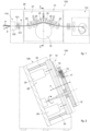
- the drawing and straightening unit 10 is suitable, for example, to feed a working machine 110, which can be a bending/shaping machine or a stirrup-making machine, which is fed with at least one elongated metal product P, for example a metal wire or round piece, advantageously two simultaneously.
- a working machine 110 which can be a bending/shaping machine or a stirrup-making machine, which is fed with at least one elongated metal product P, for example a metal wire or round piece, advantageously two simultaneously.
- the metal products P in question are typically contained in rolls or coils, disposed upstream of the apparatus for working bars 100.
- the metal products P can be characterized by very different diameters, materials and surface finishes, for example ribs.
- This variability of the metal products P is given by the need of the working machine 110 to produce a more or less complex range of finished products, for example brackets, suitable for a variety of applications.
- the drawing and straightening unit 10 has at least one first roller 12 provided peripherally with a plurality of circular grooves 13, 14, 15 inside each of which a respective metal product P to be fed is able to be positioned.
- the drawing and straightening unit 10 comprises at least one second roller 16, 17, 18 opposite the first roller 12 with respect to an axis of feed X of the at least one metal product P.
- the at least one first roller 12 is motorized and the at least one second roller 16, 17, 18 is idle and is adjustable at least vertically with respect to the first roller 12.
- the number of second rollers 16, 17, 18 is equal to the number of grooves 13, 14, 15 of the first roller 12, so that each second roller 16, 17, 18 is aligned with a respective groove 13, 14, 15.
- the first roller 12 is provided with three grooves, in particular an internal groove 15, an external groove 13 and a central groove 14 made between them.
- the grooves 13, 14, 15 are circular and have a substantially V-shaped cross section with sizes correlated to the nominal diameter of the metal products P to be fed.
- the second rollers comprise a second external roller 18, a second internal roller 16 and a second central roller 17 disposed between them.
- the second rollers 16, 17, 18 are configured to rotate independently of each other, in a way that is per se known.
- each second roller 16, 17, 18 can advantageously be moved independently toward/away from the first roller 12 in order to keep each metal product P correctly positioned inside the respective groove 13, 14, 15.
- drawing and straightening unit 10 can comprise more than one group of second rollers 16, 17, 18.
- the drawing and straightening unit 10 comprises two groups of second rollers 16, 17, 18 disposed one after the other along the axis of feed X.
- the at least one second roller 16, 17, 18 can have a smooth peripheral surface, or one provided with circumferential grooves or ridges, as shown in the example of figs. 2-3 , to carry out a more effective flattening of the metal products P.
- a feed unit 119 comprising at least one feeder unit 120 configured to slidingly support a portion in length of a certain number of metal products P to be supplied to the drawing and straightening unit 10.
- the number of metal products P supported by the feed unit 119 substantially depends on the range of finished products that the working machine 110 fed by the drawing and straightening unit 10 has to produce.
- the drawing and straightening unit 10 is mobile in a direction of adjustment Y transverse with respect to the axis of feed X in order to transversely align one or more of the grooves 13, 14, 15 with respective metal products P fed by the feed unit 119.
- the apparatus 100 comprises a support structure 126 with which there are associated at least the drawing and straightening unit 10 and favorably also the feed unit 119 and the working machine 110.
- the support structure 126 can be favorably configured to support the drawing and straightening unit 10 and the feed unit 119 in an inclined position with respect to the plane, for example the floor, where the support structure 126 is disposed resting, see for example fig. 2 .
- drawing and straightening unit 10 and the feed unit 119 can be disposed on a common lying plane, or on parallel lying planes, equally inclined with respect to the floor plane.
- the feeder body 120 is provided with guide apertures 122, 123, 124 through which respective metal products P to be supplied to the drawing and straightening unit 10 are supported slidingly.
- the feed unit 119 in particular the feeder body 120, can be disposed in such a way that at least the through axis of one of the guide apertures 122, 123, 124 that supports the metal product P to be fed is coplanar and parallel with an initial segment of the axis of feed X.
- the axis of feed X can coincide on each occasion with the through axis of one of the guide apertures 122, 123, 124.
- the feed unit 119 can comprise a pair of engagement rollers 121 disposed between the feeder body 120 and the drawing and straightening unit 10 in order to engage and draw a first segment of metal product P, for example during a format change operation.
- the guide apertures 122, 123, 124 of the feeder body 120 can have a substantially circular shape and a diameter coherent with a maximum transverse size of the metal product P to be fed.
- the guide apertures 122, 123, 124 are made through the feeder body 120 and have respective through axes parallel to each other.
- the guide apertures 122, 123, 124 are made through from one side of the feeder body 120 facing the coil magazine, to an opposite side facing toward the drawing and straightening unit 10, as shown with a dashed line in fig. 1 .
- the through axes of the guide apertures 122, 123, 124 can be coplanar or offset in some way.
- the guide apertures 122, 123 are coupled and have a substantially identical diameter, allowing the simultaneous support and sliding of two metal products P having the same geometric characteristics, while the guide aperture 124 is single and has a larger diameter than the diameter of the guide apertures 122, 123.
- the drawing and straightening unit 10 can be moved in the direction of adjustment Y with an adjustment range coherent with the position of the apertures 122, 123, 124.
- the drawing and straightening unit 10 is mobile between a waiting position and a plurality of alignment positions.
- Each alignment position is reached by moving the drawing and straightening unit 10 in such a way as to transversely align the grooves 13, 14, 15 with one or more of the guide apertures 122, 123, 124 along the axis or axes of feed X.
- the waiting position can be a generic position of the drawing and straightening unit 10 which is located between the maximum range position and the minimum range position.
- the waiting position can be the last alignment position previously reached.
- the drawing and straightening unit 10 can pass from a waiting position, for example central, to a first alignment position in which the grooves 13, 14 are aligned with the guide apertures 122, 123 along a pair of axes of feed X.
- the working machine 110 positioned downstream of the drawing and straightening unit 10 is adjusted to work two metal products P simultaneously.
- the drawing and straightening unit 10 can pass from the waiting position, for example coinciding with the previous alignment position, to a second alignment position where the groove 15 is aligned with the guide aperture 124 along the axis of feed X, in such a way that the working machine receives a single metal product P having a larger diameter.
- the direction of adjustment Y is substantially orthogonal to the axis of feed X which can be rectilinear, for example immediately at the exit from the feeder body 120, or possibly comprise a curved segment, for example in a zone comprised between the entry section and the exit section of the drawing and straightening unit 10.
- the drawing and straightening unit 10 can also comprise a plurality of yielding rollers 25 disposed upstream and downstream of the first roller 12 and of the at least one second roller 16, 17, 18, defining with them as a whole a drawing loop that delineates a curve in the axis of feed X.
- the direction of adjustment Y is parallel to the axis of rotation of the first roller 12 and of the second roller 16, 17, 18.
- the drawing and straightening unit 10 comprises an assembly defined by a mobile support 27 with which the first roller 12 and the at least one second roller 16, 17, 18 are associated, and the movement means 28 are able to move the assembly in an integral way in the direction of adjustment Y.
- the movement means 28 can be disposed between the support structure 126 and the mobile support 27.
- the mobile support 27 can be configured as a substantially flat metal plate on the external side of which the first roller 12 and the at least one second roller 16, 17, 18 are attached, in a way per se known. However, other constructive configurations are not excluded.
- the movement means 28 can comprise at least one of either a jack, a linear actuator, sliding guides, chain mechanisms, rack or grub screw mechanisms, or suchlike.
- the movement means 28 can comprise position detection devices, for example position transducers capable of identifying the position of the drawing unit 10 in the direction of adjustment Y.
- the movement means 28 comprise a pair of hydraulic cylinders 29, associated with the support structure 126 on one side and with the mobile support 27 on the opposite side, able to move the mobile support 27 in a sliding way on a pair of guides 30.
- Possible position detection devices can also be provided in association or in combination with the feed unit 119 so as to coordinate the position of the drawing and straightening unit 10, in particular of the grooves 13, 14, 15, with the position of the feed unit 119, in particular of the guide apertures 122, 123, 124.
- the feeder body 120 of the feed unit 119 can be mobile along an axis of alignment Z orthogonal to the axis of feed X and to the direction of adjustment Y.
- the feeder body 120 can comprise a plurality of guide apertures disposed at different levels on the feeder body 120, the different levels being defined at different heights along the axis of alignment Z.
- This variant can be particularly useful in the event that it is necessary to provide to feed a range of very different metal products P, without interrupting the work cycle or replacing the feeder body 120.
- At least the feeder body 120 of the feed unit 119 can also be mobile in a direction of registration substantially parallel to the direction of adjustment Y.
- a method for drawing and straightening metal products P is provided.
- the method provides:
- an adjustment step in which the drawing unit 10 is moved in the direction of adjustment Y transverse with respect to the axis of feed X so as to align one or more of the grooves 13, 14, 15 with respective metal products P supplied by the feed unit 119.
Landscapes
- Engineering & Computer Science (AREA)
- Mechanical Engineering (AREA)
- Wire Processing (AREA)
Claims (11)
- Appareil (100) pour usiner des produits métalliques comprenant une unité d'étirage et de redressage (10) pour alimenter un ou plusieurs produits métalliques (P), comprenant au moins un premier rouleau (12) muni périphériquement d'une pluralité de rainures circulaires (13, 14, 15) configuré pour accepter au moins un produit métallique (P), et au moins un second rouleau (16, 17, 18) opposé audit premier rouleau (12) par rapport à un axe d'alimentation (X) dudit au moins un produit métallique (P), caractérisé en ce qu'il existe des moyens d'ajustement (28) associé à ladite unité d'étirage et de redressage (10) et configurés pour déplacer ladite unité (10) dans une direction d'ajustement (Y) transversale par rapport audit axe d'alimentation (X) de manière à aligner, en utilisation, une ou plusieurs desdites rainures (13, 14, 15) avec des produits métalliques respectifs (P) alimentés par une unité d'alimentation (119) disposée en amont, et en ce que le nombre de seconds rouleaux (16, 17, 18) est égal au nombre de rainures (13, 14, 15) du premier rouleau (12), de sorte que chaque second rouleau (16, 17, 18) est aligné avec une rainure respective (13, 14, 15).
- Appareil (100) selon la revendication 1, caractérisé en ce que ladite direction d'ajustement (Y) est orthogonale audit axe d'alimentation (X).
- Appareil (100) selon la revendication 1 ou 2, caractérisé en ce que ladite direction d'ajustement (Y) est parallèle à l'axe de rotation dudit premier rouleau (12) et/ou dudit au moins un second rouleau (16, 17, 18).
- Appareil (100) selon l'une quelconque des revendications précédentes, caractérisé en ce qu'il comprend un ensemble défini par un support mobile (27) auquel ledit premier rouleau (12) et au moins ledit second rouleau (16, 17, 18) sont associés, et en ce que lesdits moyens de déplacement (28) sont capables de déplacer ledit ensemble dans ladite direction d'ajustement (Y).
- Appareil (100) selon l'une quelconque des revendications précédentes, caractérisé en ce que lesdits moyens de déplacement (28) comprennent au moins un élément parmi un vérin, un actionneur linéaire, des guides coulissants, des mécanismes à chaîne, des mécanismes à crémaillère ou à vis sans tête.
- Appareil (100) selon l'une quelconque des revendications précédentes, caractérisé en ce que ledit premier rouleau (12) est motorisé et est pourvu de trois rainures, dont une rainure interne (15), une rainure externe (13) et une rainure centrale (14) réalisées entre celles-ci, et en ce que lesdits seconds rouleaux sont libres et comprennent respectivement un second rouleau externe (18), un second rouleau interne (16) et un second rouleau central (17) disposés entre ceux-ci.
- Appareil (100) selon l'une quelconque des revendications précédentes, caractérisé en ce que ladite unité d'alimentation (119) comprend au moins un corps d'alimentation (120) pourvu d'ouvertures de guidage (122, 123, 124), ladite unité d'étirage et de redressage (10) étant mobile entre au moins une position d'attente et une pluralité de positions d'alignement dans lesquelles une ou plusieurs desdites rainures (13, 14, 15) sont alignées avec une ou plusieurs desdites ouvertures de guidage (122, 123, 124) le long de l'axe, ou des axes, d'alimentation (X).
- Appareil (100) selon la revendication 7, caractérisé en ce que ledit corps d'alimentation (120) est disposé de telle sorte qu'au moins l'axe traversant de l'une desdites ouvertures de guidage (122, 123, 124) est coplanaire et parallèle au moins à un segment initial dudit axe d'alimentation (X).
- Appareil (100) selon la revendication 7 ou 8, caractérisé en ce que ledit corps d'alimentation (120) de ladite unité d'alimentation (119) est mobile le long d'un axe d'alignement (Z) orthogonal audit axe d'alimentation (X) et à ladite direction d'ajustement (Y).
- Procédé d'étirage et de redressage pour alimenter un ou plusieurs produits métalliques allongés (P) vers une machine pour usiner de tels produits métalliques (P), comprenant :- une étape de fourniture d'un ou plusieurs produits métalliques (P) à une unité d'étirage et de redressage (10) effectuée par une unité d'alimentation (119) qui les supporte de manière coulissante,- une étape d'étirage desdits un ou plusieurs produits métalliques (P) au moyen de ladite unité d'étirage et de redressage (10) dans laquelle au moins un premier rouleau (12) reçoit, dans des rainures respectives (13, 14, 15), lesdits un ou plusieurs produits métalliques (P) qui sont simultanément confrontés en position par au moins un second rouleau (16, 17, 18) par rapport à un axe d'alimentation (X),caractérisé en ce qu'entre ladite étape d'alimentation et ladite étape d'étirage est prévue une étape d'ajustement dans laquelle ladite unité d'étirage et de redressage (10) est déplacée dans une direction d'ajustement (Y) transversale par rapport audit axe d'alimentation (X) de manière à aligner une ou plusieurs desdites rainures (13, 14, 15) avec des produits métalliques respectifs (P), et en ce que ladite étape d'étirage est réalisée avec un nombre de seconds rouleaux (16, 17, 18) égal au nombre de rainures (13, 14, 15) du premier rouleau (12), de sorte que chaque second rouleau (16, 17, 18) est aligné avec une rainure respective (13, 14, 15).
- Procédé selon la revendication 10, caractérisé en ce que l'étape d'étirage desdits un ou plusieurs produits métalliques (P) au moyen de ladite unité d'étirage et de redressage (10) comprend l'étirage sélectif d'une paire de produits métalliques (P) présentant un premier diamètre le long de rainures consécutives respectives (13, 14), ou l'étirage d'un produit métallique unique (P) présentant un second diamètre le long d'une autre rainure (15), dans lequel ledit second diamètre est supérieur audit premier diamètre.
Applications Claiming Priority (2)
| Application Number | Priority Date | Filing Date | Title |
|---|---|---|---|
| IT202000028259 | 2020-11-24 | ||
| PCT/IT2021/050378 WO2022113138A1 (fr) | 2020-11-24 | 2021-11-24 | Unité d'étirage et de redressage pour produits métalliques, et procédé correspondant |
Publications (2)
| Publication Number | Publication Date |
|---|---|
| EP4251343A1 EP4251343A1 (fr) | 2023-10-04 |
| EP4251343B1 true EP4251343B1 (fr) | 2024-12-04 |
Family
ID=74557148
Family Applications (1)
| Application Number | Title | Priority Date | Filing Date |
|---|---|---|---|
| EP21830347.7A Active EP4251343B1 (fr) | 2020-11-24 | 2021-11-24 | Unité d'étirage et de redressage pour produits métalliques, et procédé correspondant |
Country Status (12)
| Country | Link |
|---|---|
| US (1) | US20240091837A1 (fr) |
| EP (1) | EP4251343B1 (fr) |
| JP (1) | JP7785770B2 (fr) |
| KR (1) | KR20230118116A (fr) |
| AU (1) | AU2021389152A1 (fr) |
| DK (1) | DK4251343T3 (fr) |
| ES (1) | ES3014262T3 (fr) |
| FI (1) | FI4251343T3 (fr) |
| HU (1) | HUE070305T2 (fr) |
| PL (1) | PL4251343T3 (fr) |
| PT (1) | PT4251343T (fr) |
| WO (1) | WO2022113138A1 (fr) |
Families Citing this family (1)
| Publication number | Priority date | Publication date | Assignee | Title |
|---|---|---|---|---|
| EP4650075A1 (fr) * | 2024-05-15 | 2025-11-19 | Big Jurij GmbH | Dispositif pour dresser des profilés métalliques |
Family Cites Families (4)
| Publication number | Priority date | Publication date | Assignee | Title |
|---|---|---|---|---|
| JP3300271B2 (ja) * | 1998-01-13 | 2002-07-08 | 新興機械工業株式会社 | ばね製造機 |
| US6910360B2 (en) * | 2001-10-23 | 2005-06-28 | L&P Property Management Company | Multiple wire feed for spring coiling machine and method |
| ITUD20110210A1 (it) * | 2011-12-23 | 2013-06-24 | Piegatrici Macch Elettr | Attrezzatura per l'alimentazione di prodotti metallici ad una macchina di lavorazione e relativo procedimento |
| IT201600117662A1 (it) | 2016-11-22 | 2018-05-22 | A C M Srl Automatismi Costruzioni Mecc | Apparato di lavoro multifunzione |
-
2021
- 2021-11-24 AU AU2021389152A patent/AU2021389152A1/en active Pending
- 2021-11-24 EP EP21830347.7A patent/EP4251343B1/fr active Active
- 2021-11-24 US US18/038,350 patent/US20240091837A1/en active Pending
- 2021-11-24 WO PCT/IT2021/050378 patent/WO2022113138A1/fr not_active Ceased
- 2021-11-24 FI FIEP21830347.7T patent/FI4251343T3/fi active
- 2021-11-24 DK DK21830347.7T patent/DK4251343T3/da active
- 2021-11-24 JP JP2023531037A patent/JP7785770B2/ja active Active
- 2021-11-24 PT PT218303477T patent/PT4251343T/pt unknown
- 2021-11-24 PL PL21830347.7T patent/PL4251343T3/pl unknown
- 2021-11-24 HU HUE21830347A patent/HUE070305T2/hu unknown
- 2021-11-24 KR KR1020237021350A patent/KR20230118116A/ko active Pending
- 2021-11-24 ES ES21830347T patent/ES3014262T3/es active Active
Also Published As
| Publication number | Publication date |
|---|---|
| ES3014262T3 (en) | 2025-04-21 |
| DK4251343T3 (da) | 2025-03-03 |
| WO2022113138A1 (fr) | 2022-06-02 |
| KR20230118116A (ko) | 2023-08-10 |
| HUE070305T2 (hu) | 2025-05-28 |
| FI4251343T3 (fi) | 2025-03-04 |
| JP7785770B2 (ja) | 2025-12-15 |
| EP4251343A1 (fr) | 2023-10-04 |
| US20240091837A1 (en) | 2024-03-21 |
| JP2023553299A (ja) | 2023-12-21 |
| AU2021389152A1 (en) | 2023-06-29 |
| PT4251343T (pt) | 2025-02-28 |
| PL4251343T3 (pl) | 2025-03-31 |
| AU2021389152A9 (en) | 2025-01-16 |
Similar Documents
| Publication | Publication Date | Title |
|---|---|---|
| EP3153248B1 (fr) | Unité d'étirage et/ou de redressage pour produits métalliques oblongs, tels que des barres, des pièces rondes ou des fils métalliques | |
| EP2949407B2 (fr) | Dispositif d'étirage pour des produits allongés et procédé d'étirage correspondant | |
| EP3921097B1 (fr) | Machine pour le travail de barres et procédé de travail correspondant | |
| AU2019244944B2 (en) | Machine and method to work metal products | |
| EP4251343B1 (fr) | Unité d'étirage et de redressage pour produits métalliques, et procédé correspondant | |
| JP7164538B2 (ja) | 多機能加工装置 | |
| US20100273021A1 (en) | Flexible retaining device for a profiling installation for the flexible roll forming of cold or hot profiles with a variable cross section | |
| EP4225516B1 (fr) | Unité d'entraînement et procédé correspondant pour produits métalliques | |
| CN120306496B (zh) | 一种散热器边板冷弯成型自动化装备 | |
| US12337367B2 (en) | Apparatus and method for working oblong metal products | |
| WO2025074456A1 (fr) | Machine pour le travail de barres et procédé correspondant | |
| AU2024355020A1 (en) | Machine for working bars and corresponding method | |
| KR20250040200A (ko) | 철근 벤딩 시스템 | |
| HK1218276B (en) | Drawing unit for elongated product and corresponding drawing method |
Legal Events
| Date | Code | Title | Description |
|---|---|---|---|
| STAA | Information on the status of an ep patent application or granted ep patent |
Free format text: STATUS: UNKNOWN |
|
| STAA | Information on the status of an ep patent application or granted ep patent |
Free format text: STATUS: THE INTERNATIONAL PUBLICATION HAS BEEN MADE |
|
| PUAI | Public reference made under article 153(3) epc to a published international application that has entered the european phase |
Free format text: ORIGINAL CODE: 0009012 |
|
| STAA | Information on the status of an ep patent application or granted ep patent |
Free format text: STATUS: REQUEST FOR EXAMINATION WAS MADE |
|
| 17P | Request for examination filed |
Effective date: 20230525 |
|
| AK | Designated contracting states |
Kind code of ref document: A1 Designated state(s): AL AT BE BG CH CY CZ DE DK EE ES FI FR GB GR HR HU IE IS IT LI LT LU LV MC MK MT NL NO PL PT RO RS SE SI SK SM TR |
|
| P01 | Opt-out of the competence of the unified patent court (upc) registered |
Effective date: 20240105 |
|
| DAV | Request for validation of the european patent (deleted) | ||
| DAX | Request for extension of the european patent (deleted) | ||
| GRAP | Despatch of communication of intention to grant a patent |
Free format text: ORIGINAL CODE: EPIDOSNIGR1 |
|
| STAA | Information on the status of an ep patent application or granted ep patent |
Free format text: STATUS: GRANT OF PATENT IS INTENDED |
|
| INTG | Intention to grant announced |
Effective date: 20240624 |
|
| GRAS | Grant fee paid |
Free format text: ORIGINAL CODE: EPIDOSNIGR3 |
|
| GRAA | (expected) grant |
Free format text: ORIGINAL CODE: 0009210 |
|
| STAA | Information on the status of an ep patent application or granted ep patent |
Free format text: STATUS: THE PATENT HAS BEEN GRANTED |
|
| AK | Designated contracting states |
Kind code of ref document: B1 Designated state(s): AL AT BE BG CH CY CZ DE DK EE ES FI FR GB GR HR HU IE IS IT LI LT LU LV MC MK MT NL NO PL PT RO RS SE SI SK SM TR |
|
| REG | Reference to a national code |
Ref country code: CH Ref legal event code: EP |
|
| REG | Reference to a national code |
Ref country code: DE Ref legal event code: R096 Ref document number: 602021023028 Country of ref document: DE |
|
| REG | Reference to a national code |
Ref country code: IE Ref legal event code: FG4D |
|
| REG | Reference to a national code |
Ref country code: PT Ref legal event code: SC4A Ref document number: 4251343 Country of ref document: PT Date of ref document: 20250228 Kind code of ref document: T Free format text: AVAILABILITY OF NATIONAL TRANSLATION Effective date: 20250224 |
|
| REG | Reference to a national code |
Ref country code: DK Ref legal event code: T3 Effective date: 20250225 |
|
| REG | Reference to a national code |
Ref country code: FI Ref legal event code: FGE |
|
| REG | Reference to a national code |
Ref country code: NL Ref legal event code: FP |
|
| REG | Reference to a national code |
Ref country code: LT Ref legal event code: MG9D |
|
| PG25 | Lapsed in a contracting state [announced via postgrant information from national office to epo] |
Ref country code: HR Free format text: LAPSE BECAUSE OF FAILURE TO SUBMIT A TRANSLATION OF THE DESCRIPTION OR TO PAY THE FEE WITHIN THE PRESCRIBED TIME-LIMIT Effective date: 20241204 |
|
| PG25 | Lapsed in a contracting state [announced via postgrant information from national office to epo] |
Ref country code: BG Free format text: LAPSE BECAUSE OF FAILURE TO SUBMIT A TRANSLATION OF THE DESCRIPTION OR TO PAY THE FEE WITHIN THE PRESCRIBED TIME-LIMIT Effective date: 20241204 |
|
| REG | Reference to a national code |
Ref country code: ES Ref legal event code: FG2A Ref document number: 3014262 Country of ref document: ES Kind code of ref document: T3 Effective date: 20250421 |
|
| PG25 | Lapsed in a contracting state [announced via postgrant information from national office to epo] |
Ref country code: NO Free format text: LAPSE BECAUSE OF FAILURE TO SUBMIT A TRANSLATION OF THE DESCRIPTION OR TO PAY THE FEE WITHIN THE PRESCRIBED TIME-LIMIT Effective date: 20250304 |
|
| PG25 | Lapsed in a contracting state [announced via postgrant information from national office to epo] |
Ref country code: LV Free format text: LAPSE BECAUSE OF FAILURE TO SUBMIT A TRANSLATION OF THE DESCRIPTION OR TO PAY THE FEE WITHIN THE PRESCRIBED TIME-LIMIT Effective date: 20241204 |
|
| PG25 | Lapsed in a contracting state [announced via postgrant information from national office to epo] |
Ref country code: RS Free format text: LAPSE BECAUSE OF FAILURE TO SUBMIT A TRANSLATION OF THE DESCRIPTION OR TO PAY THE FEE WITHIN THE PRESCRIBED TIME-LIMIT Effective date: 20250304 |
|
| REG | Reference to a national code |
Ref country code: GR Ref legal event code: EP Ref document number: 20250400478 Country of ref document: GR Effective date: 20250409 |
|
| REG | Reference to a national code |
Ref country code: AT Ref legal event code: MK05 Ref document number: 1747623 Country of ref document: AT Kind code of ref document: T Effective date: 20241204 |
|
| REG | Reference to a national code |
Ref country code: HU Ref legal event code: AG4A Ref document number: E070305 Country of ref document: HU |
|
| PG25 | Lapsed in a contracting state [announced via postgrant information from national office to epo] |
Ref country code: SM Free format text: LAPSE BECAUSE OF FAILURE TO SUBMIT A TRANSLATION OF THE DESCRIPTION OR TO PAY THE FEE WITHIN THE PRESCRIBED TIME-LIMIT Effective date: 20241204 |
|
| PG25 | Lapsed in a contracting state [announced via postgrant information from national office to epo] |
Ref country code: IS Free format text: LAPSE BECAUSE OF FAILURE TO SUBMIT A TRANSLATION OF THE DESCRIPTION OR TO PAY THE FEE WITHIN THE PRESCRIBED TIME-LIMIT Effective date: 20250404 |
|
| PG25 | Lapsed in a contracting state [announced via postgrant information from national office to epo] |
Ref country code: EE Free format text: LAPSE BECAUSE OF FAILURE TO SUBMIT A TRANSLATION OF THE DESCRIPTION OR TO PAY THE FEE WITHIN THE PRESCRIBED TIME-LIMIT Effective date: 20241204 |
|
| PG25 | Lapsed in a contracting state [announced via postgrant information from national office to epo] |
Ref country code: AT Free format text: LAPSE BECAUSE OF FAILURE TO SUBMIT A TRANSLATION OF THE DESCRIPTION OR TO PAY THE FEE WITHIN THE PRESCRIBED TIME-LIMIT Effective date: 20241204 |
|
| PG25 | Lapsed in a contracting state [announced via postgrant information from national office to epo] |
Ref country code: SK Free format text: LAPSE BECAUSE OF FAILURE TO SUBMIT A TRANSLATION OF THE DESCRIPTION OR TO PAY THE FEE WITHIN THE PRESCRIBED TIME-LIMIT Effective date: 20241204 |
|
| REG | Reference to a national code |
Ref country code: DE Ref legal event code: R097 Ref document number: 602021023028 Country of ref document: DE |
|
| PG25 | Lapsed in a contracting state [announced via postgrant information from national office to epo] |
Ref country code: SE Free format text: LAPSE BECAUSE OF FAILURE TO SUBMIT A TRANSLATION OF THE DESCRIPTION OR TO PAY THE FEE WITHIN THE PRESCRIBED TIME-LIMIT Effective date: 20241204 |
|
| PLBE | No opposition filed within time limit |
Free format text: ORIGINAL CODE: 0009261 |
|
| STAA | Information on the status of an ep patent application or granted ep patent |
Free format text: STATUS: NO OPPOSITION FILED WITHIN TIME LIMIT |
|
| REG | Reference to a national code |
Ref country code: CH Ref legal event code: L10 Free format text: ST27 STATUS EVENT CODE: U-0-0-L10-L00 (AS PROVIDED BY THE NATIONAL OFFICE) Effective date: 20251015 |
|
| 26N | No opposition filed |
Effective date: 20250905 |
|
| REG | Reference to a national code |
Ref country code: CH Ref legal event code: U11 Free format text: ST27 STATUS EVENT CODE: U-0-0-U10-U11 (AS PROVIDED BY THE NATIONAL OFFICE) Effective date: 20251201 |
|
| PGFP | Annual fee paid to national office [announced via postgrant information from national office to epo] |
Ref country code: PT Payment date: 20251103 Year of fee payment: 5 |
|
| PGFP | Annual fee paid to national office [announced via postgrant information from national office to epo] |
Ref country code: NL Payment date: 20251124 Year of fee payment: 5 |
|
| PGFP | Annual fee paid to national office [announced via postgrant information from national office to epo] |
Ref country code: DE Payment date: 20251126 Year of fee payment: 5 |
|
| PGFP | Annual fee paid to national office [announced via postgrant information from national office to epo] |
Ref country code: GB Payment date: 20251125 Year of fee payment: 5 |
|
| PGFP | Annual fee paid to national office [announced via postgrant information from national office to epo] |
Ref country code: IT Payment date: 20251106 Year of fee payment: 5 |
|
| PGFP | Annual fee paid to national office [announced via postgrant information from national office to epo] |
Ref country code: FR Payment date: 20251124 Year of fee payment: 5 |
|
| PGFP | Annual fee paid to national office [announced via postgrant information from national office to epo] |
Ref country code: BE Payment date: 20251124 Year of fee payment: 5 |
|
| PGFP | Annual fee paid to national office [announced via postgrant information from national office to epo] |
Ref country code: CH Payment date: 20251201 Year of fee payment: 5 |
|
| PGFP | Annual fee paid to national office [announced via postgrant information from national office to epo] |
Ref country code: CZ Payment date: 20251111 Year of fee payment: 5 Ref country code: IE Payment date: 20251118 Year of fee payment: 5 |
|
| PGFP | Annual fee paid to national office [announced via postgrant information from national office to epo] |
Ref country code: PL Payment date: 20251029 Year of fee payment: 5 |
|
| PGFP | Annual fee paid to national office [announced via postgrant information from national office to epo] |
Ref country code: RO Payment date: 20251113 Year of fee payment: 5 |
|
| PGFP | Annual fee paid to national office [announced via postgrant information from national office to epo] |
Ref country code: ES Payment date: 20251209 Year of fee payment: 5 |