EP4251879B1 - Procédé de vidange de matières visqueuses à partir d'une cartouche ouverte des deux cotées et dispositif de vidange approprié - Google Patents
Procédé de vidange de matières visqueuses à partir d'une cartouche ouverte des deux cotées et dispositif de vidange approprié Download PDFInfo
- Publication number
- EP4251879B1 EP4251879B1 EP21815395.5A EP21815395A EP4251879B1 EP 4251879 B1 EP4251879 B1 EP 4251879B1 EP 21815395 A EP21815395 A EP 21815395A EP 4251879 B1 EP4251879 B1 EP 4251879B1
- Authority
- EP
- European Patent Office
- Prior art keywords
- cartridge
- collecting container
- emptying
- discharge
- emptying device
- Prior art date
- Legal status (The legal status is an assumption and is not a legal conclusion. Google has not performed a legal analysis and makes no representation as to the accuracy of the status listed.)
- Revoked
Links
Images





Classifications
-
- F—MECHANICAL ENGINEERING; LIGHTING; HEATING; WEAPONS; BLASTING
- F04—POSITIVE - DISPLACEMENT MACHINES FOR LIQUIDS; PUMPS FOR LIQUIDS OR ELASTIC FLUIDS
- F04B—POSITIVE-DISPLACEMENT MACHINES FOR LIQUIDS; PUMPS
- F04B13/00—Pumps specially modified to deliver fixed or variable measured quantities
-
- B—PERFORMING OPERATIONS; TRANSPORTING
- B05—SPRAYING OR ATOMISING IN GENERAL; APPLYING FLUENT MATERIALS TO SURFACES, IN GENERAL
- B05C—APPARATUS FOR APPLYING FLUENT MATERIALS TO SURFACES, IN GENERAL
- B05C11/00—Component parts, details or accessories not specifically provided for in groups B05C1/00 - B05C9/00
- B05C11/10—Storage, supply or control of liquid or other fluent material; Recovery of excess liquid or other fluent material
-
- B—PERFORMING OPERATIONS; TRANSPORTING
- B05—SPRAYING OR ATOMISING IN GENERAL; APPLYING FLUENT MATERIALS TO SURFACES, IN GENERAL
- B05C—APPARATUS FOR APPLYING FLUENT MATERIALS TO SURFACES, IN GENERAL
- B05C11/00—Component parts, details or accessories not specifically provided for in groups B05C1/00 - B05C9/00
- B05C11/10—Storage, supply or control of liquid or other fluent material; Recovery of excess liquid or other fluent material
- B05C11/1047—Apparatus or installations for supplying liquid or other fluent material comprising a buffer container or an accumulator between the supply source and the applicator
-
- B—PERFORMING OPERATIONS; TRANSPORTING
- B65—CONVEYING; PACKING; STORING; HANDLING THIN OR FILAMENTARY MATERIAL
- B65D—CONTAINERS FOR STORAGE OR TRANSPORT OF ARTICLES OR MATERIALS, e.g. BAGS, BARRELS, BOTTLES, BOXES, CANS, CARTONS, CRATES, DRUMS, JARS, TANKS, HOPPERS, FORWARDING CONTAINERS; ACCESSORIES, CLOSURES, OR FITTINGS THEREFOR; PACKAGING ELEMENTS; PACKAGES
- B65D83/00—Containers or packages with special means for dispensing contents
- B65D83/76—Containers or packages with special means for dispensing contents for dispensing fluent contents by means of a piston
-
- B—PERFORMING OPERATIONS; TRANSPORTING
- B67—OPENING, CLOSING OR CLEANING BOTTLES, JARS OR SIMILAR CONTAINERS; LIQUID HANDLING
- B67D—DISPENSING, DELIVERING OR TRANSFERRING LIQUIDS, NOT OTHERWISE PROVIDED FOR
- B67D7/00—Apparatus or devices for transferring liquids from bulk storage containers or reservoirs into vehicles or into portable containers, e.g. for retail sale purposes
- B67D7/06—Details or accessories
- B67D7/58—Arrangements of pumps
- B67D7/62—Arrangements of pumps power operated
- B67D7/64—Arrangements of pumps power operated of piston type
- B67D7/645—Barrel pumps
-
- F—MECHANICAL ENGINEERING; LIGHTING; HEATING; WEAPONS; BLASTING
- F04—POSITIVE - DISPLACEMENT MACHINES FOR LIQUIDS; PUMPS FOR LIQUIDS OR ELASTIC FLUIDS
- F04B—POSITIVE-DISPLACEMENT MACHINES FOR LIQUIDS; PUMPS
- F04B15/00—Pumps adapted to handle specific fluids, e.g. by selection of specific materials for pumps or pump parts
- F04B15/02—Pumps adapted to handle specific fluids, e.g. by selection of specific materials for pumps or pump parts the fluids being viscous or non-homogeneous
-
- F—MECHANICAL ENGINEERING; LIGHTING; HEATING; WEAPONS; BLASTING
- F04—POSITIVE - DISPLACEMENT MACHINES FOR LIQUIDS; PUMPS FOR LIQUIDS OR ELASTIC FLUIDS
- F04B—POSITIVE-DISPLACEMENT MACHINES FOR LIQUIDS; PUMPS
- F04B23/00—Pumping installations or systems
- F04B23/02—Pumping installations or systems having reservoirs
- F04B23/025—Pumping installations or systems having reservoirs the pump being located directly adjacent the reservoir
- F04B23/028—Pumping installations or systems having reservoirs the pump being located directly adjacent the reservoir the pump being mounted on top of the reservoir
Definitions
- the invention relates to the bubble-free emptying of highly viscous, i.e. pasty, substances from delivered transport containers, in particular cartridges.
- these substances or their individual components are delivered in transport containers such as cylindrical cartridges, which are usually made of plastic, with a capacity of one or more liters and the viscous material contained therein must be delivered from there to a consumer, e.g. a dosing device or a mixer, bubble-free, i.e. without air inclusions.
- transport containers such as cylindrical cartridges, which are usually made of plastic, with a capacity of one or more liters and the viscous material contained therein must be delivered from there to a consumer, e.g. a dosing device or a mixer, bubble-free, i.e. without air inclusions.
- cartridges which for the purposes of the present description should, however, include all transport containers that are open on both sides but can be closed, in which a pusher can be moved tightly inside the cartridge - which is usually cylindrical in terms of its inner circumference - and is inserted from the rear end, while the opposite front end has a generally much smaller removal opening, which is closed during transport and can be opened to remove the material.
- the material is fed out of the only opening on the top of the barrel, namely through the hollow piston rod attached to the barrel follower plate and pressing it downwards.
- the barrel follower plate must be pressed against the material with high pressure, for which the stability of the barrel itself in the radial direction is often not sufficient, but the barrel must be held together radially in an appropriate support device.
- the publication DE 10 2017 108187 A1 discloses such a device for emptying highly viscous substances from a barrel, ie from a container open on one side.
- the material is to be pushed out through the removal opening on the opposite end face by means of the pusher located therein, which can be moved along the usually round inner cross-section, which remains constant in the main direction of extension of the cartridge.
- this object is achieved in that when the material is pressed out of the removal opening by means of axial displacement of the pusher, the material is divided into a plurality of thin strands.
- the strands are dropped into a collecting container that is open at the top and mix with the flowable material present there, which is then conveyed from this collecting container to the consumer via a main conveying line connected to its lower area.
- At least the area from the division of the material into the multitude of thin strands, i.e. from the removal opening up to the upper open end of the collecting container, is kept under negative pressure during the emptying process of the cartridge and preferably also during the removal of the material from the collecting container to the consumer.
- negative pressure is understood to mean that this is in particular approximately a vacuum with a residual pressure of at most 50 mbar, preferably at most 10 mbar, preferably at most 1 mbar.
- the material is put under pressure in the direction of the discharge line opening on the collecting container at the latest after the cartridge has been completely emptied, which is preferably done by pushing a discharge piston, which is tightly guided in the collecting container, forwards from the open side in the direction of the discharge line opening, preferably in the direction of the bottom of the usually pot-shaped collecting container, where this opening is located in the bottom.
- the division of the material emerging from the discharge opening in a thick strand into a plurality of thin strands is carried out by means of a distribution head which in particular has a plurality of outlet openings for each thin strand.
- this distribution head which is preferably arranged at a distance above the open top of the collecting container during emptying of the cartridge, is then used as a discharge piston, in particular after the cartridge has been completely emptied, and is introduced into the collecting container and guided downwards in a sealed manner, for which the distribution head must have a suitable dimension.
- this does not require a separate discharge piston, and on the other hand, it avoids having to position a separate discharge piston under the distribution head and over the opening of the collecting container and only then lower it into it, which would be much more complex.
- the distribution head is not pushed axially into the collecting container alone, but together with the cartridge, at whose front end, the removal opening, it is attached, so that the cartridge acts as a plunger that moves the distribution head axially.
- the cartridge is moved axially by being fixed with its rear end in both axial directions, i.e. both upwards and downwards, in a cartridge carrier and this cartridge carrier can be moved back and forth in the pressing direction by means of a conveyor drive.
- a cartridge tappet of a cartridge drive is placed on the back of the ejector facing away from the material and pushes this ejector further forwards towards the removal opening.
- the cartridge can also be supported radially on its outer circumference.
- the area on the outside, i.e. the back, of the ejector up to the point where the cartridge tappet exits the cartridge drive is also kept under negative pressure during the emptying process so that there is no air on the back of the ejector that could penetrate into the material in the event of a leak between the ejector and the inner circumference of the cartridge.
- only the area at the rear of the cartridge tappet can be evacuated, but not up to its exit point from the cartridge drive, but only up to a front area of the cartridge tappet.
- a collecting container which is open on one side, usually at the top, and is thus pot-shaped is also provided on the base frame, in the lower area of which, in particular in the bottom, the discharge line is connected, as well as a distribution head which takes over the division of the thick rod emerging from the removal opening of the cartridge into a plurality of thin strands by comprising a plurality of small outlet openings on its outlet side.
- the distributor head has a fastening device with which it can be attached to the removal opening of the cartridge so that the thick strand emerging from it flows into the hollow interior of the distributor head and from there to the many outlet openings.
- the outlet openings In order to prevent the thin strands emerging from them from curling due to one-sided adhesion to one point on the circumference of the outlet opening, the outlet openings have a tear-off edge at their free end which surrounds the outlet opening and has a sharp, pointed tear-off edge with an angle of less than 70°, preferably less than 50°, preferably less than 40°, in cross-section.
- the distribution head which is attached directly to the front lower end of the cartridge and in the underside of which the outlet openings are located, to be able to be inserted tightly into the collecting container, its outer circumference must correspond to the inner circumference of the collecting container and a sealing lip is preferably provided on the outer circumference of the distribution head.
- the outer diameter of the distribution head must be larger than the outer diameter of the cartridge, as the latter partially protrudes into the collection container during operation.
- a discharge drive which can move the cartridge carrier relative to the base frame towards and away from the collecting container, preferably consisting of two discharge working cylinders on opposite sides with respect to the cartridge carrier.
- a first vacuum housing is provided, which is sleeve-shaped and rests on the one hand on the outer circumference of the collecting container, and on the other hand on the outer circumference of the cartridge aligned with it, whereby the seal against the cartridge allows a relative movement of the cartridge to this vacuum housing in order to retract the cartridge upwards to such an extent that that its removal opening and, above all, a distribution head attached to it are located at a distance above the collection container.
- the cartridge holder in the cartridge carrier is open on one side or can at least be opened to insert the cartridge from the side, for which the cartridge carrier is positioned at such a height that the lower removal opening of the cartridge including the distribution head is at a distance above the open top of the collection container.
- the ring-shaped lid of the sleeve-shaped first vacuum housing is pushed onto the outer circumference of the cartridge from below and then the distribution head is fixed, in particular screwed, onto the lower end of the cartridge, which is only possible after pushing on the lid, since it has a larger outer diameter than the cartridge.
- the cover of the first vacuum housing and the distribution head are attached to the cartridge - or to a support sleeve that surrounds the cartridge to minimize radial expansion of the cartridge when pressure is applied - before the cartridge is hung in the emptying device.
- the lid can then be pushed down until it is secured and sealed against the sleeve-shaped lower part of the first vacuum housing, which is preferably always located on the collecting container.
- the upper end of the cartridge, in which the ejector is located when filled is located within a second, cap-shaped vacuum housing, which sits tightly on the upper edge of the cartridge at the bottom and is sealed at the top against the circumference of the cartridge tappet, which runs through it.
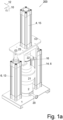
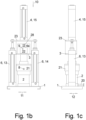
- the emptying device consists of a base frame 1 in the form of a base plate 1 - preferably with side wheels that are bent downwards and inwards against each other for sliding around a guide 501 as in Figure 5 shown - on the first
- Two discharge working cylinders 13, 14, here in the form of pneumatic cylinders, are arranged at a distance in the transverse direction 11, which together form the discharge drive 6, since they are arranged with their pressing directions 10 parallel to one another and the respective piston rod 13a, 14a can be extended vertically upwards from their respective cylinder 13b, 14b.
- the cartridge carrier 3 consists of a rectangular profile which is open on at least one side in the second transverse direction 12, preferably continuously, and which is preferably fastened to the underside of the yoke 23, which is narrow enough in the first transverse direction 11 to penetrate between the two discharge working cylinders 13, 14.
- a second transverse direction 12 - see Figure 1a - open, U-shaped recess, continuous from top to bottom, which is dimensioned such that a cartridge 100 can be hung thereon with its edge 100b1 running around the filling opening 100b and pointing outwards, by inserting the cartridge 100 in the second transverse direction 12 into the cartridge holder 16 such that it rests with the filling opening 100b pointing upwards with this upper edge 100b1 on the cartridge carrier 3, i.e. its edge region running around the cartridge holder 16, and preferably with the aid of a fixing device 3a, as shown in the enlargement of the Figure 2b presented, held.
- the cartridge 100 extends through the cartridge holder 16 and points downwards with its generally smaller removal opening 100a at the opposite end.
- this removal opening 100a is closed in the transport state by a closure element, usually a closure screw 102 that can be screwed onto the thread, in particular the internal thread 100a1 of the removal opening 100a, and inserted into the opposite filling opening 100b there is a pot-shaped ejector 101 that fits tightly against the inner circumference of the cartridge 100, the friction of which is so great that it is not possible for it to move out of the filling opening 100b by itself, even through the material M present between the ejector 101 and the closure element 102.
- a closure element usually a closure screw 102 that can be screwed onto the thread, in particular the internal thread 100a1 of the removal opening 100a, and inserted into the opposite filling opening 100b there is a pot-shaped ejector 101 that fits tightly against the inner circumference of the cartridge 100, the friction of which is so great that it is not possible for it to move out of the filling opening 100b by itself, even through the material M present between the ejector 101 and the closure element 102.
- the closure element 102 is removed and instead a distribution head 7 is fastened to the removal opening 100a, preferably with its own thread, in particular external thread, screwed as a fastening device 7a to the thread, in particular internal thread 100a1, which will be explained later.
- the cartridge is already equipped with such a distribution head 7, which, when viewed from above, has a larger transverse extension, in particular a larger diameter, than the cartridge 100.
- a collecting container 2 is mounted on the base frame 1, in particular the base plate 1, between the two discharge working cylinders 13, 14 and in alignment with the cartridge working cylinder 15 - which is usually also pneumatically operated - and the cartridge 100 fixed in the cartridge holder 16.
- the distribution head 7 fits tightly into the upwardly open, pot-shaped collecting container 2.
- the yoke 23 can be raised so far that the distribution head 7 is located above the collecting container 2 and can be moved down so far that the distribution head 7 sits on the bottom of the collecting container 2.
- the piston rod, i.e. the cartridge tappet 15a, of the cartridge working cylinder 15 carries a press head 24 at the lower, free end, the downward-facing front surface of which is adapted to the concave curvature of the upper side of the ejector 101 and fits into it.
- the cartridge working cylinder 15 is dimensioned such that when the piston rod 15a is completely retracted into its cylinder 15b, i.e. raised, the press head 24 is at a height completely above the suspended cartridge 100 and, in the fully extended state, close to the bottom of the cartridge 100 at its removal opening 100a, with only the cup-shaped ejector 101 in between.
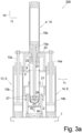
- a cartridge 100 In order to supply material M from the cartridge 100 to the discharge line 20 and thus to the consumer, a cartridge 100 must first be installed in the emptying device as shown in Figure 2a shown.
- annular cover 21b of a first vacuum housing 21 is pushed from the emptying end onto the outer circumference of the cartridge 100 or - if present - the support sleeve 103 so far that the distribution head 7 can then be fastened to the lower removal opening 100a, in particular can be screwed into its internal thread 100a1.
- the cartridge 100 - optionally with surrounding support sleeve 103 as well as cover 21b and distribution head 7 - is then inserted into the cartridge holder 16 in the second transverse direction 12 and the edge 100b1 and optionally the edge of the support sleeve 103 located underneath are pressed firmly onto the top of the cartridge holder 16 by means of the fixing device 3a, whereby these parts are preferably sealed against one another by concentrically encircling O-rings 27 located between them.
- the two discharge working cylinders 13, 14 are extended with respect to their piston rods 13a, 14a to such an extent that the distribution head 7 attached to the cartridge 100 is then located at a height above, but vertically aligned with, the collecting container 2.
- the cartridge 100 is fixed in all horizontal directions, so that this represents a first part of the fixing device 3a, and at the latest when the press head 24 is immersed in the cartridge 100, the press piston is released from the bottom of the second, pot-shaped vacuum housing 22, so that this now presses downwards onto the laterally projecting edge 100b1 with its lower annular edge - which represents the second part of the fixing device 3a - by means of a spiral spring 28, which is arranged concentrically around the piston rod 15a between this second vacuum housing 22 and the yoke 23, more precisely the top of the cartridge carrier 3, which is rectangular in side view.
- both the cartridge carrier 3 and the cartridge 100 and the press head 24 located in the lower area thereof move downwards together, whereby the distribution head 7 firstly moves into the upper open end of the collecting container 2 - the inner circumference of which is conically widened upwards at the upper end to facilitate insertion - and moves further downwards with its circumferential sealing lip 25 tightly fitting against its inner circumference, initially until the distribution head 7 sits on the material M located in the collecting container 2.
- the distribution head 7 acts as a discharge piston 5 and pushes the material downwards out of the collecting container 2 into the discharge line 20 and thus to the distant consumer.
- the material M is degassed as follows:
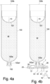
- the task of the distribution head as in Figure 4c shown in perspective, consists in dividing material M emerging through the removal opening 100a in a single thick strand, which enters the top of the internally hollow distribution head 7, into a plurality of thin strands S1, S2, S3 by arranging a plurality of outlet openings 17 with a comparatively small diameter in the underside of the distribution head 7.
- the strands S1, S2 fall parallel to one another downwards into the collecting container 2, instead of deflecting sideways as is possible with one-sided adhesion and reuniting very quickly with neighboring strands S2, S3, because this large surface area, which is maintained on the thin strands S1, S2, S3 for as long as possible, is needed in order to open gas inclusions in the strand and allow the gas to escape.
- the distribution head 7 is located above the collecting container 2, which is why it is also necessary for the strands S1, S2, S3 to fall straight downwards.
- the first vacuum housing 21 is provided, which is provided with a vacuum connection 8 and whose upper, ring-shaped cover 21b with its upper through-opening lies tightly against the outer circumference of the cartridge 100 and whose sleeve-shaped lower part 21a with its lower through-opening lies tightly against the outer circumference of the collecting container 2, each sealed, for example, via O-rings 27.
- the cartridge tappet 15a of the cartridge working cylinder 15 can be pushed tightly through an opening in the upwardly facing bottom of the pot-shaped second vacuum housing 22, with O-rings 27 preferably being used again for sealing.
- this vacuum housing 22 is sucked out via the vacuum connection 9, which is also present on it, as soon as it sits on the cartridge and before the press head 24 moves into the cartridge, for which purpose the second vacuum housing 22 is preferably dimensioned such that the press head 24 does not lie tightly against the inner circumference of the pot-shaped second vacuum housing 22.
- a vent valve 30 can be present in the rear side, the top side, of the distribution head 7 facing away from the material, i.e. the bottom of the collecting container 2, which would release air entering the hollow interior of the distribution head 7 via the lower outlet openings 17 upwards into the first vacuum.
- This vent valve 29 can be a simple membrane which is permeable to air but not to the material M to be conveyed.
- any air inclusions still present in the material M in the cartridge 100 can be removed before the material M reaches the consumer via the discharge line 20.
- Figure 5 shows a typical dosing unit with a doser 300, via whose dosing nozzle 301 the viscous material M is to be dosed in exactly specified quantities.
- the emptying device 200 is connected to the dosing device 300 via the discharge line 20, whereby both the dosing device 300 and the emptying device 200 preferably have an analogously designed base plate 1, so that both can be pushed onto the same guide 501 and positioned at the correct distance from each other.
Landscapes
- Engineering & Computer Science (AREA)
- Mechanical Engineering (AREA)
- General Engineering & Computer Science (AREA)
- Containers And Packaging Bodies Having A Special Means To Remove Contents (AREA)
- Basic Packing Technique (AREA)
- Reciprocating Pumps (AREA)
Claims (15)
- Procédé de vidange sans bulles de matière visqueuse (M) d'une cartouche (100) ouverte des deux côtés qui présente un expulseur (101) y reposant de manière étanche et y étant déplaçable dans la direction de pressage (10), ainsi que, à l'autre extrémité, une ouverture de prélèvement (100a) pouvant être fermée, en ce que- par poussée vers l'avant, c'est-à-dire en direction de l'ouverture de prélèvement (100a), de l'expulseur (101), la matière (M) est expulsée de l'ouverture de prélèvement (100a),
caractérisé en ce que- lors de l'expulsion, la matière (M) est répartie en une pluralité de branches minces (S1, S2, S3),- les branches (S1, S2, S3) sont laissées tomber dans un récipient collecteur (2) ouvert en haut, à l'ouverture de sortie (29) duquel en particulier une conduite d'évacuation (20) est raccordée de manière étanche dans sa zone inférieure,- au moins la zone allant de la répartition de la matière (M) dans la pluralité de branches minces (S1, S2, S3) jusqu'à l'extrémité supérieure ouverte du récipient collecteur (2) est maintenue sous pression pendant le processus de vidange. - Procédé selon la revendication 1,
caractérisé en ce que
la dépression est un vide avec une pression résiduelle d'au plus 50 mbar, en particulier d'au plus 10 mbar, en particulier d'au plus 1 mbar. - Procédé selon l'une quelconque des revendications précédentes,
caractérisé en ce que- au plus tard après l'expulsion complète de la matière (M) hors de la cartouche (100), la matière (M) se trouvant dans le récipient collecteur (2) est mise sous pression en direction de l'ouverture de sortie (29), c'est-à-dire l'embouchure de la conduite d'évacuation (20),- en particulier par poussée vers l'avant d'un piston d'évacuation (5) guidé de manière étanche dans le récipient collecteur (2). - Procédé selon l'une quelconque des revendications précédentes,
caractérisé en ce que- la répartition de la matière (M) en une pluralité de branches minces (S1, S2, S3) est effectuée au moyen d'une tête de répartition (7) qui présente en particulier une pluralité d'ouvertures de sortie (17) pour respectivement une branche mince (S1, S2, S3),- la tête de répartition (7) est également utilisée en tant que piston d'évacuation (5). - Procédé selon l'une quelconque des revendications précédentes,
caractérisé en ce que- pour l'expulsion hors de la cartouche (100), un poussoir de cartouche (15a) d'un entraînement de cartouche (4) est appliqué sur l'expulseur (101) et pousse celui-ci vers l'avant. - Procédé selon l'une quelconque des revendications précédentes,
caractérisé en ce que- pour la poussée vers l'avant du piston d'évacuation (5) dans le récipient collecteur (2), celui-ci est inséré dans le récipient collecteur (2) et poussé vers l'avant dans l'ouverture de sortie (29) et en particulier en direction de la conduite d'évacuation (20),- en particulier, la cartouche entière (100) avec le piston d'évacuation (5) qui y est fixé est poussée vers l'avant en direction de l'ouverture de sortie (29). - Procédé selon l'une quelconque des revendications précédentes,
caractérisé en ce que
la zone sur le côté extérieur, c'est-à-dire le côté arrière, de l'expulseur (101) jusqu'au point de sortie du poussoir de cartouche (15a) de l'entraînement de cartouche (4) est maintenue sous pression pendant le processus de vidange. - Dispositif de vidange (200) pour vider une matière visqueuse d'une cartouche (100) ouverte des deux côtés qui présente un expulseur (101) y reposant de manière étanche et y étant déplaçable dans la direction de pressage (10), ainsi que, à l'autre extrémité, une ouverture de prélèvement (100a) pouvant être fermée, en particulier pour mettre en oeuvre le procédé selon l'une quelconque des revendications précédentes, avec- un châssis de base (1),- un récipient collecteur (2) y étant fixé pour une matière (M),- un support de cartouche (3) qui est guidé de manière mobile dans la direction de pressage (10) par rapport au châssis de base (1),- un entraînement de cartouche (4) avec un poussoir de cartouche (15a) pour pousser vers l'avant l'expulseur (101) de la cartouche (100),- un piston d'évacuation (5) guidé de manière étanche dans le récipient collecteur (2),- un entraînement d'évacuation (6) pour déplacer le piston d'évacuation (5),
caractérisé en ce que- le support de cartouche (3) présente un dispositif de fixation (3a) au moyen duquel la cartouche (100) peut être fixée de manière fixe sur le support de cartouche (3) dans et contre la direction de pressage (10),- une tête de répartition (7) pour la répartition de la branche de matière (M) sortant de l'ouverture de prélèvement (100a) en une pluralité de branches minces (S1, S2, S3), qui présente un dispositif de fixation (7a) pour la fixation à l'ouverture de prélèvement (100a),- la tête de répartition (7) s'adapte de manière étanche et mobile dans la direction de pressage (10) dans le récipient collecteur (2) et peut être utilisée en tant que piston d'évacuation (5),- un premier boîtier à vide (21) étanche à la pression avec un raccord de dépression (8) est présent, lequel repose de manière étanche contre le récipient collecteur (2) et de manière étanche contre la circonférence extérieure de la cartouche (100), même lorsque celle-ci se déplace par rapport au boîtier à vide (21). - Dispositif de vidange selon la revendication 8,
caractérisé en ce que- un deuxième boîtier à vide (22) étanche à la pression est présent avec un raccord de dépression (9) qui, d'une part, repose de manière étanche contre la circonférence extérieure de la cartouche (100) au-dessus du logement de cartouche (16) dans le support de cartouche (3) et, d'autre part, est traversé de manière étanche par le poussoir de cartouche (15a). - Dispositif de vidange selon l'une quelconque des revendications précédentes,
caractérisé en ce que
la tête de répartition (7) est conçue de sorte qu'elle puisse être fixée à une distance fixe de l'ouverture de prélèvement (100a) de la cartouche (100) dans la direction de pressage (10). - Dispositif de vidange selon l'une quelconque des revendications précédentes,
caractérisé en ce que- l'entraînement d'évacuation (6) est disposé entre le support de cartouche (3) et le châssis de base (1)- un entraînement d'évacuation (6) est disposé en particulier des deux côtés du logement de cartouche (16),- l'entraînement d'évacuation (6) comprend au moins un, en particulier deux, vérins de travail d'évacuation (13, 14). - Dispositif de vidange selon l'une quelconque des revendications précédentes,
caractérisé en ce que- l'entraînement de cartouche (4) comprend au moins un vérin de travail de cartouche (15). - Dispositif de vidange selon l'une quelconque des revendications précédentes,
caractérisé en ce que
le logement de cartouche (16) dans le support de cartouche (3) est ouvert ou peut être ouvert sur le côté pour l'introduction latérale d'une cartouche (100). - Dispositif de vidange selon l'une quelconque des revendications précédentes,
caractérisé en ce que
le poussoir de cartouche (15a) traverse un deuxième boîtier à vide (22) en forme de cloche et un ressort spiral (28) agissant en tant que ressort de pression est disposé entre la culasse (23) et l'extrémité supérieure du boîtier à vide (22). - Unité de dosage (500) avec un doseur (300) pour le dosage de matière visqueuse ainsi qu'un dispositif de vidange (200) pour vider une matière visqueuse d'une cartouche (100) ouverte des deux côtés.
caractérisée en ce que
le dispositif de vidange (200) est conçu selon l'une quelconque des revendications 8 à 14.
Applications Claiming Priority (2)
| Application Number | Priority Date | Filing Date | Title |
|---|---|---|---|
| DE102020131081.1A DE102020131081B3 (de) | 2020-11-24 | 2020-11-24 | Verfahren zum Entleeren von viskosem Material aus einer beidseitig offenen Kartusche sowie hierfür geeignete Entleer-Vorrichtung |
| PCT/EP2021/081528 WO2022112022A1 (fr) | 2020-11-24 | 2021-11-12 | Procédé pour vider un matériau visqueux d'une cartouche ouverte des deux côtés, et dispositif de vidage conçu à cet effet |
Publications (2)
| Publication Number | Publication Date |
|---|---|
| EP4251879A1 EP4251879A1 (fr) | 2023-10-04 |
| EP4251879B1 true EP4251879B1 (fr) | 2025-01-08 |
Family
ID=78232214
Family Applications (1)
| Application Number | Title | Priority Date | Filing Date |
|---|---|---|---|
| EP21815395.5A Revoked EP4251879B1 (fr) | 2020-11-24 | 2021-11-12 | Procédé de vidange de matières visqueuses à partir d'une cartouche ouverte des deux cotées et dispositif de vidange approprié |
Country Status (5)
| Country | Link |
|---|---|
| US (1) | US20230294906A1 (fr) |
| EP (1) | EP4251879B1 (fr) |
| JP (1) | JP2023552709A (fr) |
| DE (1) | DE102020131081B3 (fr) |
| WO (1) | WO2022112022A1 (fr) |
Families Citing this family (2)
| Publication number | Priority date | Publication date | Assignee | Title |
|---|---|---|---|---|
| GB2625788A (en) * | 2022-12-23 | 2024-07-03 | Medmix Switzerland Ag | Method of emptying a cartridge |
| CN119702369B (zh) * | 2023-09-27 | 2025-10-10 | 苏州卓兆点胶股份有限公司 | 光伏电池生产用供胶装置 |
Citations (10)
| Publication number | Priority date | Publication date | Assignee | Title |
|---|---|---|---|---|
| DE7913800U1 (de) | 1979-05-12 | 1979-08-16 | Schieferdecker Gmbh & Co Kg | Kartusche fuer plastische Massen |
| FR2544699A1 (fr) | 1983-04-21 | 1984-10-26 | Fraco Sa | Dispositif pour vider des recipients contenant des produits thermofusibles |
| DE9209500U1 (de) | 1992-05-05 | 1992-10-01 | Schieferdecker Gmbh & Co Kg, 4006 Erkrath | Einwegbehälter zur Aufnahme pastöser Medien |
| DE10058283A1 (de) | 2000-11-23 | 2002-06-13 | Heitz Walter Helmut | Kartuschensystem |
| DE102005049805A1 (de) | 2005-08-19 | 2007-02-22 | Erich Scheugenpflug | Entleervorrichtung |
| DE102013110774A1 (de) | 2013-09-30 | 2015-04-02 | Sig Technology Ag | Vorrichtung zur Veränderung der Strahlform von fließfähigen Produkten |
| DE102014114374B3 (de) | 2014-10-02 | 2016-03-10 | Scheugenpflug Ag | Entleervorrichtung mit einer Fasspresse sowie Verfahren zum Entleeren von viskosem Material |
| DE102017108187A1 (de) | 2017-04-18 | 2018-10-18 | Scheugenpflug Ag | Entleervorrichtung für viskose Stoffe sowie Verfahren hierfür |
| DE102018131266A1 (de) | 2018-12-07 | 2020-06-10 | Heraeus Medical Gmbh | Vorrichtung zum Mischen eines Knochenzements mit Hohlraum zum Monomertransfer |
| EP3705721A1 (fr) | 2019-03-08 | 2020-09-09 | Nordson Corporation | Appareil de mélange et de transport d'un milieu fusible reçu dans un récipient |
Family Cites Families (14)
| Publication number | Priority date | Publication date | Assignee | Title |
|---|---|---|---|---|
| US3272393A (en) * | 1963-12-13 | 1966-09-13 | John O Roeser | Apparatus and method for precision metering and deposit of viscous materials |
| US3478925A (en) * | 1967-11-13 | 1969-11-18 | Simmonds Precision Products | Viscous dispensing system |
| US5336052A (en) * | 1993-04-28 | 1994-08-09 | Abel Pumpen Gmbh & Co. Kg | Viscous material pump |
| US5494194A (en) * | 1993-12-10 | 1996-02-27 | White Consolidated Industries, Inc. | Viscous material dispenser |
| DE69630152T2 (de) * | 1995-12-01 | 2004-07-08 | Sunstar Engineering Inc., Takatsuki | Vorrichtung zum Schäumen eines viskosen Materials |
| US20080130219A1 (en) * | 1999-05-11 | 2008-06-05 | Josef Rabinovitz | Enclosure for computer peripheral devices |
| US7271999B2 (en) * | 1999-05-11 | 2007-09-18 | Josef Rabinovitz | Enclosure for computer peripheral devices |
| US6415955B1 (en) * | 2001-03-20 | 2002-07-09 | David Ostreicher | Plaster ejector gun with disposable cartridge |
| US8048439B2 (en) * | 2003-11-17 | 2011-11-01 | Btg International Ltd. | Therapeutic foam |
| US9845259B2 (en) * | 2009-01-03 | 2017-12-19 | General Ecology, Inc. | Apparatus for filtering and/or conditioning and/or purifying a fluid such as water |
| US9908765B2 (en) * | 2010-03-10 | 2018-03-06 | C.H.& I. Technologies, Inc. | Method for distributing product using a consumer refillable packaging in a retail environment |
| US20160038957A1 (en) * | 2014-08-06 | 2016-02-11 | Illinois Tool Works Inc. | Remote bulk feed system for a dispensing system and method of supplying viscous material to a dispensing system |
| US9976782B1 (en) * | 2016-12-18 | 2018-05-22 | Frostime LLC | Portable instant cooling system with controlled temperature obtained through timed-release liquid or gaseous CO2 coolant for general refrigeration use in mobile and stationary containers |
| US10675653B2 (en) * | 2017-02-07 | 2020-06-09 | Nordson Corporation | Motorized cartridge type fluid dispensing apparatus and system |
-
2020
- 2020-11-24 DE DE102020131081.1A patent/DE102020131081B3/de not_active Withdrawn - After Issue
-
2021
- 2021-11-12 EP EP21815395.5A patent/EP4251879B1/fr not_active Revoked
- 2021-11-12 JP JP2023530638A patent/JP2023552709A/ja active Pending
- 2021-11-12 WO PCT/EP2021/081528 patent/WO2022112022A1/fr not_active Ceased
-
2023
- 2023-05-22 US US18/200,485 patent/US20230294906A1/en active Pending
Patent Citations (10)
| Publication number | Priority date | Publication date | Assignee | Title |
|---|---|---|---|---|
| DE7913800U1 (de) | 1979-05-12 | 1979-08-16 | Schieferdecker Gmbh & Co Kg | Kartusche fuer plastische Massen |
| FR2544699A1 (fr) | 1983-04-21 | 1984-10-26 | Fraco Sa | Dispositif pour vider des recipients contenant des produits thermofusibles |
| DE9209500U1 (de) | 1992-05-05 | 1992-10-01 | Schieferdecker Gmbh & Co Kg, 4006 Erkrath | Einwegbehälter zur Aufnahme pastöser Medien |
| DE10058283A1 (de) | 2000-11-23 | 2002-06-13 | Heitz Walter Helmut | Kartuschensystem |
| DE102005049805A1 (de) | 2005-08-19 | 2007-02-22 | Erich Scheugenpflug | Entleervorrichtung |
| DE102013110774A1 (de) | 2013-09-30 | 2015-04-02 | Sig Technology Ag | Vorrichtung zur Veränderung der Strahlform von fließfähigen Produkten |
| DE102014114374B3 (de) | 2014-10-02 | 2016-03-10 | Scheugenpflug Ag | Entleervorrichtung mit einer Fasspresse sowie Verfahren zum Entleeren von viskosem Material |
| DE102017108187A1 (de) | 2017-04-18 | 2018-10-18 | Scheugenpflug Ag | Entleervorrichtung für viskose Stoffe sowie Verfahren hierfür |
| DE102018131266A1 (de) | 2018-12-07 | 2020-06-10 | Heraeus Medical Gmbh | Vorrichtung zum Mischen eines Knochenzements mit Hohlraum zum Monomertransfer |
| EP3705721A1 (fr) | 2019-03-08 | 2020-09-09 | Nordson Corporation | Appareil de mélange et de transport d'un milieu fusible reçu dans un récipient |
Non-Patent Citations (4)
| Title |
|---|
| ANONYMOUS: "Kartuschenpistole", WIKIPEDIA, 13 December 2022 (2022-12-13), XP093325810, Retrieved from the Internet <URL:https://de.wikipedia.org/w/index.php?title=Kartuschenpistole&oldid=228831244> |
| D12 - CHRONOLOGISCHER HANDELSREGISTERAUSZUG DER EINSPRECHENDEN |
| D13 - AKTUELLER HANDELSREGISTERAUSZUG DER PATENTINHABERIN |
| D14 - CHRONOLOGISCHER HANDELSREGISTERAUSZUG DER SCHEUGENPFLUG AG, RECHTSVORGÄNGERIN DER EINSPRECHENDEN |
Also Published As
| Publication number | Publication date |
|---|---|
| WO2022112022A1 (fr) | 2022-06-02 |
| JP2023552709A (ja) | 2023-12-19 |
| US20230294906A1 (en) | 2023-09-21 |
| DE102020131081B3 (de) | 2021-11-11 |
| EP4251879A1 (fr) | 2023-10-04 |
Similar Documents
| Publication | Publication Date | Title |
|---|---|---|
| EP0412480B1 (fr) | Dispositif de remplissage de récipients | |
| DE102014114374B3 (de) | Entleervorrichtung mit einer Fasspresse sowie Verfahren zum Entleeren von viskosem Material | |
| EP4251879B1 (fr) | Procédé de vidange de matières visqueuses à partir d'une cartouche ouverte des deux cotées et dispositif de vidange approprié | |
| EP3596001B1 (fr) | Dispositif d'évacuation d'un contenant avec un liquide pâteux | |
| EP2788275A1 (fr) | Élément de remplissage pourvu d'un tube trinox | |
| EP2652451A1 (fr) | Dispositif de dosage de poudre et procédé de dosage de poudre | |
| DE102021109816A1 (de) | Verfahren zum Entleeren von viskosem Material aus einer beidseitig offenen Kartusche sowie hierfür geeignete Entleer-Vorrichtung | |
| DE102013005965A1 (de) | Vorrichtung zum Abdichten und Evakuieren eines Behälters mit insbesondere pastöser Flüssigkeit | |
| DE102015122147B4 (de) | Füll-Verfahren für Pulver und hierzu geeignete Vorrichtung | |
| DE19841478A1 (de) | Dosiervorrichtung mit ausziehbarer Dichtung | |
| DE102012207587B4 (de) | Verfahren und Vorrichtung zum Füllen von Karpulen mit einem Füllgut | |
| EP0943583A1 (fr) | Procédé et dispositif pour la distribution de matériau visqueux | |
| DE4340235C2 (de) | Vorrichtung zum kontinuierlichen Abführen viskoser Materialien aus Behältern | |
| DE19853593C1 (de) | Füllvorrichtung für Kartuschen | |
| EP4530247B1 (fr) | Dispositif avec plaque d'essuyage pour un récipient de stockage de matériau et appareil de déchargement avec ledit dispositif | |
| EP4516707A1 (fr) | Dispositif de vidange pour vider un récipient | |
| EP3523201B1 (fr) | Dispositif de remplissage pour une empaqueteuse de produits en vrac dans des récipients | |
| DE3121821A1 (de) | "vorrichtung zur entleerung von insbesondere pasteuse massen enthaltenden zylindrischen behaeltern" | |
| DE102014012171B4 (de) | Vorrichtung zum Auspressen von viskosen Massen aus Behältern | |
| DE4310282C2 (de) | Behälter für pastöse Druckfarben | |
| DE202017101507U1 (de) | Vorrichtung zum Evakuieren eines Behälters mit pastöser Flüssigkeit | |
| DE102004016006A1 (de) | Gebinde und dafür vorgesehenes Gebindeentleerungssystem | |
| DE102023111260A1 (de) | Vergussanlage und Verfahren | |
| DE102013103418A1 (de) | Verfahren sowie Füllsystem zum Füllen von Behältern mit einem flüssigen Füllgut | |
| EP0615923B1 (fr) | Installation d'arrosage |
Legal Events
| Date | Code | Title | Description |
|---|---|---|---|
| STAA | Information on the status of an ep patent application or granted ep patent |
Free format text: STATUS: UNKNOWN |
|
| STAA | Information on the status of an ep patent application or granted ep patent |
Free format text: STATUS: THE INTERNATIONAL PUBLICATION HAS BEEN MADE |
|
| PUAI | Public reference made under article 153(3) epc to a published international application that has entered the european phase |
Free format text: ORIGINAL CODE: 0009012 |
|
| STAA | Information on the status of an ep patent application or granted ep patent |
Free format text: STATUS: REQUEST FOR EXAMINATION WAS MADE |
|
| 17P | Request for examination filed |
Effective date: 20230519 |
|
| AK | Designated contracting states |
Kind code of ref document: A1 Designated state(s): AL AT BE BG CH CY CZ DE DK EE ES FI FR GB GR HR HU IE IS IT LI LT LU LV MC MK MT NL NO PL PT RO RS SE SI SK SM TR |
|
| DAV | Request for validation of the european patent (deleted) | ||
| DAX | Request for extension of the european patent (deleted) | ||
| GRAP | Despatch of communication of intention to grant a patent |
Free format text: ORIGINAL CODE: EPIDOSNIGR1 |
|
| STAA | Information on the status of an ep patent application or granted ep patent |
Free format text: STATUS: GRANT OF PATENT IS INTENDED |
|
| INTG | Intention to grant announced |
Effective date: 20240808 |
|
| GRAS | Grant fee paid |
Free format text: ORIGINAL CODE: EPIDOSNIGR3 |
|
| GRAA | (expected) grant |
Free format text: ORIGINAL CODE: 0009210 |
|
| STAA | Information on the status of an ep patent application or granted ep patent |
Free format text: STATUS: THE PATENT HAS BEEN GRANTED |
|
| AK | Designated contracting states |
Kind code of ref document: B1 Designated state(s): AL AT BE BG CH CY CZ DE DK EE ES FI FR GB GR HR HU IE IS IT LI LT LU LV MC MK MT NL NO PL PT RO RS SE SI SK SM TR |
|
| RAP3 | Party data changed (applicant data changed or rights of an application transferred) |
Owner name: DOSMATIX GMBH |
|
| REG | Reference to a national code |
Ref country code: GB Ref legal event code: FG4D Free format text: NOT ENGLISH |
|
| REG | Reference to a national code |
Ref country code: CH Ref legal event code: EP |
|
| REG | Reference to a national code |
Ref country code: DE Ref legal event code: R096 Ref document number: 502021006389 Country of ref document: DE |
|
| REG | Reference to a national code |
Ref country code: IE Ref legal event code: FG4D Free format text: LANGUAGE OF EP DOCUMENT: GERMAN |
|
| REG | Reference to a national code |
Ref country code: LT Ref legal event code: MG9D |
|
| REG | Reference to a national code |
Ref country code: NL Ref legal event code: MP Effective date: 20250108 |
|
| PG25 | Lapsed in a contracting state [announced via postgrant information from national office to epo] |
Ref country code: NL Free format text: LAPSE BECAUSE OF FAILURE TO SUBMIT A TRANSLATION OF THE DESCRIPTION OR TO PAY THE FEE WITHIN THE PRESCRIBED TIME-LIMIT Effective date: 20250108 |
|
| PG25 | Lapsed in a contracting state [announced via postgrant information from national office to epo] |
Ref country code: RS Free format text: LAPSE BECAUSE OF FAILURE TO SUBMIT A TRANSLATION OF THE DESCRIPTION OR TO PAY THE FEE WITHIN THE PRESCRIBED TIME-LIMIT Effective date: 20250408 |
|
| PG25 | Lapsed in a contracting state [announced via postgrant information from national office to epo] |
Ref country code: FI Free format text: LAPSE BECAUSE OF FAILURE TO SUBMIT A TRANSLATION OF THE DESCRIPTION OR TO PAY THE FEE WITHIN THE PRESCRIBED TIME-LIMIT Effective date: 20250108 |
|
| PG25 | Lapsed in a contracting state [announced via postgrant information from national office to epo] |
Ref country code: PL Free format text: LAPSE BECAUSE OF FAILURE TO SUBMIT A TRANSLATION OF THE DESCRIPTION OR TO PAY THE FEE WITHIN THE PRESCRIBED TIME-LIMIT Effective date: 20250108 |
|
| PG25 | Lapsed in a contracting state [announced via postgrant information from national office to epo] |
Ref country code: ES Free format text: LAPSE BECAUSE OF FAILURE TO SUBMIT A TRANSLATION OF THE DESCRIPTION OR TO PAY THE FEE WITHIN THE PRESCRIBED TIME-LIMIT Effective date: 20250108 |
|
| PG25 | Lapsed in a contracting state [announced via postgrant information from national office to epo] |
Ref country code: IS Free format text: LAPSE BECAUSE OF FAILURE TO SUBMIT A TRANSLATION OF THE DESCRIPTION OR TO PAY THE FEE WITHIN THE PRESCRIBED TIME-LIMIT Effective date: 20250508 Ref country code: NO Free format text: LAPSE BECAUSE OF FAILURE TO SUBMIT A TRANSLATION OF THE DESCRIPTION OR TO PAY THE FEE WITHIN THE PRESCRIBED TIME-LIMIT Effective date: 20250408 |
|
| PG25 | Lapsed in a contracting state [announced via postgrant information from national office to epo] |
Ref country code: HR Free format text: LAPSE BECAUSE OF FAILURE TO SUBMIT A TRANSLATION OF THE DESCRIPTION OR TO PAY THE FEE WITHIN THE PRESCRIBED TIME-LIMIT Effective date: 20250108 |
|
| PG25 | Lapsed in a contracting state [announced via postgrant information from national office to epo] |
Ref country code: PT Free format text: LAPSE BECAUSE OF FAILURE TO SUBMIT A TRANSLATION OF THE DESCRIPTION OR TO PAY THE FEE WITHIN THE PRESCRIBED TIME-LIMIT Effective date: 20250508 Ref country code: LV Free format text: LAPSE BECAUSE OF FAILURE TO SUBMIT A TRANSLATION OF THE DESCRIPTION OR TO PAY THE FEE WITHIN THE PRESCRIBED TIME-LIMIT Effective date: 20250108 |
|
| PG25 | Lapsed in a contracting state [announced via postgrant information from national office to epo] |
Ref country code: GR Free format text: LAPSE BECAUSE OF FAILURE TO SUBMIT A TRANSLATION OF THE DESCRIPTION OR TO PAY THE FEE WITHIN THE PRESCRIBED TIME-LIMIT Effective date: 20250409 Ref country code: BG Free format text: LAPSE BECAUSE OF FAILURE TO SUBMIT A TRANSLATION OF THE DESCRIPTION OR TO PAY THE FEE WITHIN THE PRESCRIBED TIME-LIMIT Effective date: 20250108 |
|
| PG25 | Lapsed in a contracting state [announced via postgrant information from national office to epo] |
Ref country code: SE Free format text: LAPSE BECAUSE OF FAILURE TO SUBMIT A TRANSLATION OF THE DESCRIPTION OR TO PAY THE FEE WITHIN THE PRESCRIBED TIME-LIMIT Effective date: 20250108 |
|
| PG25 | Lapsed in a contracting state [announced via postgrant information from national office to epo] |
Ref country code: SM Free format text: LAPSE BECAUSE OF FAILURE TO SUBMIT A TRANSLATION OF THE DESCRIPTION OR TO PAY THE FEE WITHIN THE PRESCRIBED TIME-LIMIT Effective date: 20250108 |
|
| REG | Reference to a national code |
Ref country code: DE Ref legal event code: R026 Ref document number: 502021006389 Country of ref document: DE |
|
| PG25 | Lapsed in a contracting state [announced via postgrant information from national office to epo] |
Ref country code: DK Free format text: LAPSE BECAUSE OF FAILURE TO SUBMIT A TRANSLATION OF THE DESCRIPTION OR TO PAY THE FEE WITHIN THE PRESCRIBED TIME-LIMIT Effective date: 20250108 |
|
| PLBI | Opposition filed |
Free format text: ORIGINAL CODE: 0009260 |
|
| REG | Reference to a national code |
Ref country code: CH Ref legal event code: L10 Free format text: ST27 STATUS EVENT CODE: U-0-0-L10-L00 (AS PROVIDED BY THE NATIONAL OFFICE) Effective date: 20251015 |
|
| PLAX | Notice of opposition and request to file observation + time limit sent |
Free format text: ORIGINAL CODE: EPIDOSNOBS2 |
|
| PG25 | Lapsed in a contracting state [announced via postgrant information from national office to epo] |
Ref country code: CZ Free format text: LAPSE BECAUSE OF FAILURE TO SUBMIT A TRANSLATION OF THE DESCRIPTION OR TO PAY THE FEE WITHIN THE PRESCRIBED TIME-LIMIT Effective date: 20250108 Ref country code: EE Free format text: LAPSE BECAUSE OF FAILURE TO SUBMIT A TRANSLATION OF THE DESCRIPTION OR TO PAY THE FEE WITHIN THE PRESCRIBED TIME-LIMIT Effective date: 20250108 |
|
| PG25 | Lapsed in a contracting state [announced via postgrant information from national office to epo] |
Ref country code: RO Free format text: LAPSE BECAUSE OF FAILURE TO SUBMIT A TRANSLATION OF THE DESCRIPTION OR TO PAY THE FEE WITHIN THE PRESCRIBED TIME-LIMIT Effective date: 20250108 |
|
| PG25 | Lapsed in a contracting state [announced via postgrant information from national office to epo] |
Ref country code: SK Free format text: LAPSE BECAUSE OF FAILURE TO SUBMIT A TRANSLATION OF THE DESCRIPTION OR TO PAY THE FEE WITHIN THE PRESCRIBED TIME-LIMIT Effective date: 20250108 |
|
| PLBB | Reply of patent proprietor to notice(s) of opposition received |
Free format text: ORIGINAL CODE: EPIDOSNOBS3 |
|
| 26 | Opposition filed |
Opponent name: ATLAS COPCO EPS GMBH Effective date: 20251007 |
|
| RDAF | Communication despatched that patent is revoked |
Free format text: ORIGINAL CODE: EPIDOSNREV1 |
|
| REG | Reference to a national code |
Ref country code: DE Ref legal event code: R064 Ref document number: 502021006389 Country of ref document: DE Ref country code: DE Ref legal event code: R103 Ref document number: 502021006389 Country of ref document: DE |
|
| PGFP | Annual fee paid to national office [announced via postgrant information from national office to epo] |
Ref country code: AT Payment date: 20260113 Year of fee payment: 5 |
|
| PG25 | Lapsed in a contracting state [announced via postgrant information from national office to epo] |
Ref country code: IT Free format text: LAPSE BECAUSE OF FAILURE TO SUBMIT A TRANSLATION OF THE DESCRIPTION OR TO PAY THE FEE WITHIN THE PRESCRIBED TIME-LIMIT Effective date: 20250108 |
|
| RDAG | Patent revoked |
Free format text: ORIGINAL CODE: 0009271 |
|
| STAA | Information on the status of an ep patent application or granted ep patent |
Free format text: STATUS: PATENT REVOKED |
|
| REG | Reference to a national code |
Ref country code: CH Ref legal event code: N12 Free format text: ST27 STATUS EVENT CODE: U-0-0-N10-N12 (AS PROVIDED BY THE NATIONAL OFFICE) Effective date: 20260225 |
|
| 27W | Patent revoked |
Effective date: 20251114 |
|
| GBPR | Gb: patent revoked under art. 102 of the ep convention designating the uk as contracting state |
Effective date: 20251114 |