EP4252535A1 - Systèmes de distribution de liquide pour pulvérisateurs de culture comprenant un capteur de qualité d'eau, et procédés associés - Google Patents
Systèmes de distribution de liquide pour pulvérisateurs de culture comprenant un capteur de qualité d'eau, et procédés associés Download PDFInfo
- Publication number
- EP4252535A1 EP4252535A1 EP23164288.5A EP23164288A EP4252535A1 EP 4252535 A1 EP4252535 A1 EP 4252535A1 EP 23164288 A EP23164288 A EP 23164288A EP 4252535 A1 EP4252535 A1 EP 4252535A1
- Authority
- EP
- European Patent Office
- Prior art keywords
- water quality
- product tank
- sensor
- quality property
- liquid
- Prior art date
- Legal status (The legal status is an assumption and is not a legal conclusion. Google has not performed a legal analysis and makes no representation as to the accuracy of the status listed.)
- Pending
Links
Images



Classifications
-
- A—HUMAN NECESSITIES
- A01—AGRICULTURE; FORESTRY; ANIMAL HUSBANDRY; HUNTING; TRAPPING; FISHING
- A01C—PLANTING; SOWING; FERTILISING
- A01C23/00—Distributing devices specially adapted for liquid manure or other fertilising liquid, including ammonia, e.g. transport tanks or sprinkling wagons
- A01C23/007—Metering or regulating systems
-
- A—HUMAN NECESSITIES
- A01—AGRICULTURE; FORESTRY; ANIMAL HUSBANDRY; HUNTING; TRAPPING; FISHING
- A01M—CATCHING, TRAPPING OR SCARING OF ANIMALS; APPARATUS FOR THE DESTRUCTION OF NOXIOUS ANIMALS OR NOXIOUS PLANTS
- A01M7/00—Special adaptations or arrangements of liquid-spraying apparatus for purposes covered by this subclass
- A01M7/005—Special arrangements or adaptations of the spraying or distributing parts, e.g. adaptations or mounting of the spray booms, mounting of the nozzles, protection shields
-
- A—HUMAN NECESSITIES
- A01—AGRICULTURE; FORESTRY; ANIMAL HUSBANDRY; HUNTING; TRAPPING; FISHING
- A01C—PLANTING; SOWING; FERTILISING
- A01C23/00—Distributing devices specially adapted for liquid manure or other fertilising liquid, including ammonia, e.g. transport tanks or sprinkling wagons
- A01C23/04—Distributing under pressure; Distributing mud; Adaptation of watering systems for fertilising-liquids
- A01C23/047—Spraying of liquid fertilisers
-
- A—HUMAN NECESSITIES
- A01—AGRICULTURE; FORESTRY; ANIMAL HUSBANDRY; HUNTING; TRAPPING; FISHING
- A01G—HORTICULTURE; CULTIVATION OF VEGETABLES, FLOWERS, RICE, FRUIT, VINES, HOPS OR SEAWEED; FORESTRY; WATERING
- A01G25/00—Watering gardens, fields, sports grounds or the like
- A01G25/16—Control of watering
-
- A—HUMAN NECESSITIES
- A01—AGRICULTURE; FORESTRY; ANIMAL HUSBANDRY; HUNTING; TRAPPING; FISHING
- A01M—CATCHING, TRAPPING OR SCARING OF ANIMALS; APPARATUS FOR THE DESTRUCTION OF NOXIOUS ANIMALS OR NOXIOUS PLANTS
- A01M7/00—Special adaptations or arrangements of liquid-spraying apparatus for purposes covered by this subclass
- A01M7/0082—Undercarriages, frames, mountings, couplings, tanks
- A01M7/0085—Tanks
-
- B—PERFORMING OPERATIONS; TRANSPORTING
- B05—SPRAYING OR ATOMISING IN GENERAL; APPLYING FLUENT MATERIALS TO SURFACES, IN GENERAL
- B05B—SPRAYING APPARATUS; ATOMISING APPARATUS; NOZZLES
- B05B12/00—Arrangements for controlling delivery; Arrangements for controlling the spray area
- B05B12/08—Arrangements for controlling delivery; Arrangements for controlling the spray area responsive to condition of liquid or other fluent material to be discharged, of ambient medium or of target ; responsive to condition of spray devices or of supply means, e.g. pipes, pumps or their drive means
Definitions
- Embodiments of the present disclosure relate to mobile application machines, such as self-propelled sprayers and similar vehicles. More particularly, embodiments relate to liquid distribution systems for applying chemicals.
- High crop yields of modern agribusiness typically require application of fertilizers, pesticides, fungicides, and/or herbicides. Dispersing these chemicals onto highacreage fields requires specialized machines mounted on or towed by a vehicle. An example of such a machine is the self-propelled sprayer.
- a common design for a self-propelled crop sprayer includes a chassis with a tank, boom arms, and nozzles connected to the boom arms.
- the tank contains liquid product such as fertilizers, pesticides, fungicides, and/or herbicides.
- Boom arms extend outward from the sides of the chassis.
- Boom plumbing contains supply lines and nozzles spaced apart along the length of the boom arms at a spacing distance corresponding to the spray pattern of the nozzles.
- the length of conventional boom arms may vary from, for example, 6 meters (18 feet) up to 46 meters (150 feet), but shorter or longer booms are possible.
- the boom arms typically swing in for on-road transport and out for field-spraying operations.
- the nozzles are connected in series such that the product flows through a pipe and/or hose from one nozzle to another.
- Booms have been of the "wet boom” type, where the boom comprises a frame member with a pipe mounted thereon, where the liquid passes through the pipe into nozzles mounted on the pipe and liquidly connected thereto, or a “dry boom” type, where the nozzles are mounted to the frame member and liquid passes to the nozzles through a hose which is connected between the nozzles.
- the nozzles are attached to the pipe or frame with brackets at desired intervals along the boom arm.
- the product When a sprayer is first used to dispense a particular product, the product may be flushed through the pipe or hose to each nozzle to fill entire plumbing system with the product. This may help to remove air bubbles and ensure that any prior products are purged from the system. To avoid uneven distribution of the product, this flushing and purging process may be performed before the sprayer enters the planted area of the field. This process may dispense several gallons of product out of the boom to ensure that all of the air is out of the boom and that liquid product can consistently and evenly be dispensed from each of the nozzles.
- a liquid distribution system for a crop sprayer includes a product tank configured to contain a liquid, a pump in fluid communication with the product tank, and a plurality of nozzles carried by a boom and configured to receive the liquid from the pump through at least one plumbing line.
- the product tank has a fluid inlet, and at least one water quality sensor is configured to detect a water quality property of liquid entering the product tank through the fluid inlet.
- the at least one water quality sensor can include, for example, a pH sensor, a turbidity sensor, a dissolved oxygen sensor, a salinity sensor, an ammonia sensor, a chlorine sensor, a nitrate sensor, a sulfite sensor, a total organic carbon sensor, and/or a sensor for detecting any other element or ion, without limitation.
- the at least one water quality sensor may be disposed within the product tank, and may be disposed to measure the water quality property of the liquid in the product tank.
- the at least one water quality sensor may be configured to report the water quality property to an operator of the crop sprayer.
- the crop sprayer may also include a rinse tank configured to contain rinse water separate from the liquid in the product tank.
- the water quality sensor is configured measure the water quality property of the rinse water entering the product tank through the fluid inlet.
- the liquid distribution system may optionally include a mixing device within the product tank, and the sensor may be configured to detect the water quality property of liquid passing through the mixing device.
- Methods of operating a crop sprayer include providing fresh water to a product tank of the crop sprayer, measuring a first water quality property of the fresh water entering the product tank, circulating the fresh water within the product tank to form a rinsate, measuring a second water quality property of the rinsate in the product tank, comparing the second water quality property to the first water quality property, removing the rinsate from the product tank, and if a difference between the second water quality property and the first water quality property is greater than a preselected threshold, providing additional fresh water to the product tank to form a second rinsate.
- the product tank may optionally be drained before providing fresh water to the product tank.
- Measuring the first and second water quality properties may include measuring the water quality properties of fresh water or the rinsate passing a sensor within the product tank. Both water quality properties (i.e., the first water quality property of the fresh water and the second water quality property of the rinsate) may be measured by a single sensor.
- the water quality properties may include, without limitation, pH, turbidity, dissolved oxygen, salinity, ammonia concentration, chloride concentration, nitrate concentration, sulfite concentration, total organic carbon, and/or any other element or ion concentration.
- removing the rinsate from the product tank may include spraying at least a portion of the rinsate through nozzles carried by a boom of the crop sprayer.
- the terms “comprising,” “including,” “containing,” “characterized by,” and grammatical equivalents thereof are inclusive or open-ended terms that do not exclude additional, unrecited elements or method steps, but also include the more restrictive terms “consisting of” and “consisting essentially of” and grammatical equivalents thereof.
- the term "may” with respect to a material, structure, feature, or method act indicates that such is contemplated for use in implementation of an embodiment of the disclosure, and such term is used in preference to the more restrictive term “is” so as to avoid any implication that other, compatible materials, structures, features, and methods usable in combination therewith should or must be excluded.
- the term “configured” refers to a size, shape, material composition, and arrangement of one or more of at least one structure and at least one apparatus facilitating operation of one or more of the structure and the apparatus in a predetermined way.
- spatially relative terms such as “beneath,” “below,” “lower,” “bottom,” “above,” “upper,” “top,” “front,” “rear,” “left,” “right,” and the like, may be used for ease of description to describe one element's or feature's relationship to another element(s) or feature(s) as illustrated in the figures. Unless otherwise specified, the spatially relative terms are intended to encompass different orientations of the materials in addition to the orientation depicted in the figures.
- the term "substantially" in reference to a given parameter, property, or condition means and includes to a degree that one of ordinary skill in the art would understand that the given parameter, property, or condition is met with a degree of variance, such as within acceptable manufacturing tolerances.
- the parameter, property, or condition may be at least 90.0% met, at least 95.0% met, at least 99.0% met, or even at least 99.9% met.
- ranges are used as shorthand for describing each and every value that is within the range. Any value within the range can be selected as the terminus of the range.
- FIG. 1 shows a crop sprayer 102 used to deliver chemicals to agricultural crops in a field.
- the crop sprayer 102 includes a chassis 104 and an operator cab 106 mounted on the chassis 104.
- the operator cab 106 may house controls for the crop sprayer 102.
- An engine 108 may be mounted on a forward portion of the chassis 104 in front of operator cab 106 or may be mounted on a rearward portion of the chassis 104 behind the operator cab 106.
- the engine 108 may be commercially available from a variety of sources and may include, for example, a diesel engine or a gasoline powered internal combustion engine, a battery-powered electric motor, etc.
- the engine 108 provides energy to propel the crop sprayer 102 through a field on wheels or tracks, and may also provide energy to spray liquids from the crop sprayer 102.
- the crop sprayer 102 further includes a product tank 110 to store a liquid to be sprayed on the field.
- the liquid may include chemicals, such as but not limited to, herbicides, pesticides, fungicides, and/or fertilizers.
- the product tank 110 may be mounted on the chassis 104, either in front of or behind the operator cab 106.
- the crop sprayer 102 may include more than one product tank 110 to store different chemicals to be sprayed on the field. The stored chemicals may be dispersed by the crop sprayer 102 one at a time, or different chemicals may be mixed and dispersed together in a variety of mixtures.
- a boom 112 on the crop sprayer 102 is used to distribute the liquid from the product tank 110 over a wide swath as the crop sprayer 102 is driven through the field.
- the boom 112 may include two or more portions that can fold for transport on public roadways, and unfold (i.e., to the position shown in FIG. 1 ) for field operations.
- FIG. 2 is a simplified perspective view of a portion of the boom 112.
- Liquid is conveyed from the product tank 110 ( FIG. 1 ) by a liquid distribution system 202 to various nozzles 204 carried by and spaced along the boom 112.
- the liquid distribution system 202 which may be mounted on the boom 112, includes at least one supply line and, optionally, a recirculation line connected to the product tank 110. Recirculation of liquid to the product tank 110 may be useful for purging lines when changing products without wasting product onto the ground or damaging crops with excess product. In some embodiments, the recirculation line may be omitted, and the liquid distribution system 202 can be purged at a shop or mixing plant, where liquid can be captured, such as on a catch pad.
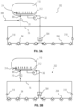
- FIG. 3A is a simplified schematic view of the liquid distribution system 202 of the crop sprayer 102 shown in FIG. 1 and FIG. 2 .
- a pump 302 is in fluid communication with the product tank 110.
- the nozzles 204 are configured to receive liquid from the product tank 110 via the pump 302, and optionally, a flow splitter 304 (e.g., to split flow into two or more portions to supply different sections of the boom 112).
- the product tank 110 can be filled through a fluid inlet 306 by fresh water 308 from an external source (e.g., a well, a pond, a canal, a municipal supply, etc.) or from a rinse tank.
- the fresh water 308 flows into the product tank 110 via a valve 310.
- a mixing device 312 such as a nozzle or sparge tube, may distribute the fresh water 308 entering the product tank 110 and encourage mixing with the liquid already in the product tank 110.
- the fresh water 308 passes a water quality sensor 314 as it enters the product tank 110, which sensor 314 is configured to detect one or more water quality property of the fresh water 308.
- the liquid in the product tank 110 may be mixed continuously, not just when filling with fresh water 308, by passing the liquid in the product tank 110 through the mixing device 312.
- the sensor 314 may be placed within the flow path of the mixing device 312 in the product tank 110, such that any time liquid is circulating in the product tank 110, a flow of liquid passes the sensor 314.
- the sensor 314 may be, for example, a pH sensor, a turbidity sensor, a dissolved oxygen sensor, a salinity sensor, an ammonia sensor, a chloride sensor, a nitrate sensor, a sulfite sensor, a total organic carbon sensor, a sensor for detecting any other element or ion, or any other selected sensor.
- the sensor 306 may include an instrument capable of detecting multiple water quality properties, such as those available from Eureka Water Probes, of Austin, Texas, under the names Trimeter and Manta+.
- the sensor 314 measures at least one water quality property (e.g., pH, turbidity, dissolved oxygen, salinity, ammonia concentration, chloride concentration, nitrate concentration, sulfite concentration, total organic carbon, concentration of another element or ion, etc .) of the fresh water 308.
- the sensor 314 measures the water quality property(ies) of the liquid in the product tank 110.
- FIG. 3B is a simplified schematic view of the liquid distribution system 202 in a recirculation mode.
- the pump 302 provides liquid through the flow splitter 304 to the nozzles 204.
- the nozzles 204 may or may not be spraying liquid onto the field when the liquid distribution system 202 is in recirculation mode, depending on the pressure at each nozzle 204. That is, the nozzles 204 may spray liquid only when pressure at the nozzles 204 is above a threshold.
- valves may control flow to individual nozzles 204.
- a recirculation line 316 can recycle liquid through check valves 318 and the valve 310 back to the product tank 110.
- the recirculation line 316 may be used to prime the liquid distribution system 202 to apply a new liquid, to clean out the liquid distribution system 202 after use, and/or to ensure consistent mixing throughout a liquid application process.
- the fresh water 308 ( FIG. 3A ) supply is disconnected, and the recirculating liquid passes the sensor 314, which measures the water quality property(ies) of the recirculating liquid in the liquid distribution system 202.
- the sensor 314 can measure the water quality property(ies) of the liquid. This property can be reported to an operator of the crop sprayer 102, such as through a computer in the operator cab 106.
- the computer may also compare the current value of the water quality property to the value of the water quality property previously measured for the fresh water 308, and this information may be used by the operator to determine whether the liquid distribution system 202 is clean enough to switch to distributing a different material.
- the product tank 110 may be at least partially drained of the liquid therein. Removing all of the liquid from the product tank 110 is typically not feasible in operational settings, and therefore a rinse cycle is used to protect crops to be subsequently treated (which crops could be damaged by the material applied previously).
- fresh water 308 is provided to the product tank 110 and circulated within the product tank 110 to form a rinsate (i.e., a mixture of the fresh water 308 with the residual liquid from the prior spraying operation).
- the sensor 314 measures a water quality property of the fresh water 308.
- the rinsate After terminating the flow of the fresh water 308, the rinsate is circulated within the product tank 110 and/or through the recirculation line 316. After a period of time, the rinsate may have a substantially uniform concentration of the material previously applied (e.g., the herbicide).
- the sensor 314 may continually measure the water quality property, and the operator or a computer may use the information about the water quality property to determine when the rinsate is uniformly mixed. The operator or a computer may compare the water quality property of the rinsate with the previously measured water quality property of the fresh water 308 to determine whether the rinsate is sufficiently clean.
- the rinsate is removed from the product tank, and additional fresh water 308 is provided to the product tank.
- the process can be repeated as many times as necessary until a desired difference between the rinsate and fresh water is observed.
- the rinsate (or second rinsate, third rinsate, etc.) is drained from the product tank 110, and the product tank 110 can be filled with the next liquid to be applied (e.g., the fungicide, and optionally including water to yield a preselected concentration), or the product tank 110 can be kept empty until its next use.
- the rinsate can be drained by spraying it out the nozzles 204, thus cleaning the nozzles 204 themselves.
- the rinsate may be withdrawn from the product tank 110 through a drain port, or may be flushed through a drain valve on the boom 112 or elsewhere in the liquid distribution system 202.
- the quality of fresh water 308 can vary greatly depending on the source. However, because the water quality property of the fresh water 308 is measured while the product tank 110 is filling, variance in the water quality property can be easily accounted for in a cleaning procedure. In particular, the water quality property of the rinsate can be compared to the water quality property of the fresh water 308, rather than to a preselected standard. In other words, measurement of the water quality property of the fresh water 308 can serve as a calibration against which the rinsate can be compared.
- the sensor 314 measures chloride concentration
- the fresh water 308 has a chloride concentration of 12 mg/l
- a chloride concentration in the rinsate of 25 mg/l would indicate that 13 mg/l is due to residual herbicide in the rinsate.
- the operator would then drain the product tank 110 and rinse again with additional fresh water 308, and could repeat the process as many times as necessary to reach the standard.
- the product tank and plumbing lines of conventional crop sprayers are typically flushed with fresh water and/or a cleaning solution (e.g., a surfactant) according to prescribed procedures or protocols.
- a cleaning solution e.g., a surfactant
- an equipment or chemical manufacturer may recommend rinsing equipment once with a specified cleaning solution, and twice with fresh water, after applying a certain product.
- the crop sprayer 102 may not have a recirculation line 316.
- the plumbing lines in the boom 112 may be cleaned by pumping the rinsate from the product tank 110 and out the nozzles 204, where it can be captured and disposed of.
- the sensor 314 in such embodiments can still measure the water quality property of the fresh water 308 and of the rinsate circulating through the mixing device 312 within the product tank 110.
- FIG. 4 is a simplified schematic view of another liquid distribution system 402, which is similar to the liquid distribution system 202 shown in FIG. 3A .
- the liquid distribution system 402 also includes a rinse tank 404 carried by the crop sprayer 102 and configured to contain a supply of rinse water (typically fresh water, but optionally including a cleaning agent).
- the valve 310 can direct the rinse water into the product tank 110 and past the sensor 314, which measures the water quality property(ies) of the rinse water in the same manner described above.
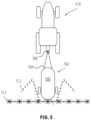
- FIG. 5 shows another crop sprayer 502 that may be used to deliver chemicals to agricultural crops in a field.
- the crop sprayer 502 is a pull-type sprayer including a chassis 504 carrying a product tank 506.
- the crop sprayer 502 has a hitch 508 configured to couple the chassis 504 to a tractor 510.
- the tractor 510 may therefore pull the crop sprayer 502 through the field, and the operator of the tractor 510 may also operate the crop sprayer 502 via a control system in the cab of the tractor 510.
- the boom 112 may have arms that fold for road transport (partially folded boom arms indicated by dashed lines in FIG. 5 ).
- the crop sprayer 502 may also include a sensor 314 as shown in FIG. 3A and FIG. 3B and described above.
Landscapes
- Life Sciences & Earth Sciences (AREA)
- Engineering & Computer Science (AREA)
- Environmental Sciences (AREA)
- Water Supply & Treatment (AREA)
- Soil Sciences (AREA)
- Insects & Arthropods (AREA)
- Pest Control & Pesticides (AREA)
- Wood Science & Technology (AREA)
- Zoology (AREA)
- Catching Or Destruction (AREA)
Applications Claiming Priority (1)
| Application Number | Priority Date | Filing Date | Title |
|---|---|---|---|
| US202263362015P | 2022-03-28 | 2022-03-28 |
Publications (1)
| Publication Number | Publication Date |
|---|---|
| EP4252535A1 true EP4252535A1 (fr) | 2023-10-04 |
Family
ID=85775957
Family Applications (1)
| Application Number | Title | Priority Date | Filing Date |
|---|---|---|---|
| EP23164288.5A Pending EP4252535A1 (fr) | 2022-03-28 | 2023-03-27 | Systèmes de distribution de liquide pour pulvérisateurs de culture comprenant un capteur de qualité d'eau, et procédés associés |
Country Status (2)
| Country | Link |
|---|---|
| US (1) | US20230301229A1 (fr) |
| EP (1) | EP4252535A1 (fr) |
Cited By (1)
| Publication number | Priority date | Publication date | Assignee | Title |
|---|---|---|---|---|
| WO2026038096A1 (fr) * | 2024-08-15 | 2026-02-19 | Precision Planting Llc | Procédés et système de rinçage d'un réservoir de fluide |
Citations (4)
| Publication number | Priority date | Publication date | Assignee | Title |
|---|---|---|---|---|
| EP2617286B1 (fr) * | 2012-01-20 | 2018-07-04 | Amazonen-Werke H. Dreyer GmbH & Co. KG | Pulvérisateur agricole à cultures |
| WO2018213596A1 (fr) * | 2017-05-17 | 2018-11-22 | Spogen Biotech Inc. | Dispositifs, systèmes et procédés de détection agrochimique et compositions agrochimiques |
| US20190009285A1 (en) * | 2016-03-29 | 2019-01-10 | Agco Corporation | An Agricultural Sprayer and Associated Method |
| US20200047206A1 (en) * | 2018-08-07 | 2020-02-13 | Deere & Company | Residue detection system |
-
2023
- 2023-03-27 EP EP23164288.5A patent/EP4252535A1/fr active Pending
- 2023-03-27 US US18/190,214 patent/US20230301229A1/en active Pending
Patent Citations (4)
| Publication number | Priority date | Publication date | Assignee | Title |
|---|---|---|---|---|
| EP2617286B1 (fr) * | 2012-01-20 | 2018-07-04 | Amazonen-Werke H. Dreyer GmbH & Co. KG | Pulvérisateur agricole à cultures |
| US20190009285A1 (en) * | 2016-03-29 | 2019-01-10 | Agco Corporation | An Agricultural Sprayer and Associated Method |
| WO2018213596A1 (fr) * | 2017-05-17 | 2018-11-22 | Spogen Biotech Inc. | Dispositifs, systèmes et procédés de détection agrochimique et compositions agrochimiques |
| US20200047206A1 (en) * | 2018-08-07 | 2020-02-13 | Deere & Company | Residue detection system |
Cited By (1)
| Publication number | Priority date | Publication date | Assignee | Title |
|---|---|---|---|---|
| WO2026038096A1 (fr) * | 2024-08-15 | 2026-02-19 | Precision Planting Llc | Procédés et système de rinçage d'un réservoir de fluide |
Also Published As
| Publication number | Publication date |
|---|---|
| US20230301229A1 (en) | 2023-09-28 |
Similar Documents
| Publication | Publication Date | Title |
|---|---|---|
| US20220151216A1 (en) | Agricultural spraying system | |
| US10334776B2 (en) | Method and system having an intermediate holding vessel for combining chemical injection substances for a spray system | |
| US20240206449A1 (en) | Liquid Distribution Systems for Crop Sprayers, and Related Methods | |
| EP4252535A1 (fr) | Systèmes de distribution de liquide pour pulvérisateurs de culture comprenant un capteur de qualité d'eau, et procédés associés | |
| US20240081315A1 (en) | Sprayer System | |
| AU709685B2 (en) | A spray system for need dosage | |
| US20240109094A1 (en) | Agricultural sprayer cleaning systems and methods for same | |
| US20250098659A1 (en) | Sprayer Vehicles, Liquid Distribution Systems for Sprayer Vehicles Comprising a Water Quality Sensor, and Related Methods | |
| US20220330537A1 (en) | Agricultural spraying system | |
| US20250311716A1 (en) | Method and sprayer system for calibrating dosing valves for fluid injection | |
| WO2024224188A1 (fr) | Systèmes de distribution de liquide, pulvérisateurs agricoles et procédés associés | |
| BR102024016279A2 (pt) | Veículos pulverizadores, sistemas de distribuição de líquidos para veículos pulverizadores compreendendo um sensor de qualidade de água e métodos relacionados | |
| CN207201602U (zh) | 可移动喷洒车 | |
| Ozkan | Herbicide application equipment | |
| US20250081957A1 (en) | Crop Sprayers, Liquid Distribution Systems for Crop Sprayers, and Related Methods | |
| AU2023340647A1 (en) | Liquid distribution systems, crop sprayers, and related methods | |
| AU2023391432A1 (en) | Liquid distribution systems for crop sprayers | |
| US20250360526A1 (en) | Computer Vision Control of Spray Nozzles and Related Systems, Circuitry, and Methods | |
| CN203435475U (zh) | 多功能生物全降解液态地膜喷洒机 | |
| WO2025109395A1 (fr) | Systèmes de distribution de liquide, pulvérisateurs pour cultures et procédés associés | |
| CN219593492U (zh) | 一种移动式打药装置 | |
| US20250359503A1 (en) | Methods of Measuring a Flowrate Through a Pulse Width Modulation Valve, and Related Agricultural Machines and Monitoring Systems | |
| WO2026038096A1 (fr) | Procédés et système de rinçage d'un réservoir de fluide | |
| Cordes | Sprayer Attachment for Zero Turn Lawn Mower |
Legal Events
| Date | Code | Title | Description |
|---|---|---|---|
| PUAI | Public reference made under article 153(3) epc to a published international application that has entered the european phase |
Free format text: ORIGINAL CODE: 0009012 |
|
| STAA | Information on the status of an ep patent application or granted ep patent |
Free format text: STATUS: THE APPLICATION HAS BEEN PUBLISHED |
|
| AK | Designated contracting states |
Kind code of ref document: A1 Designated state(s): AL AT BE BG CH CY CZ DE DK EE ES FI FR GB GR HR HU IE IS IT LI LT LU LV MC ME MK MT NL NO PL PT RO RS SE SI SK SM TR |
|
| STAA | Information on the status of an ep patent application or granted ep patent |
Free format text: STATUS: REQUEST FOR EXAMINATION WAS MADE |
|
| 17P | Request for examination filed |
Effective date: 20240404 |
|
| RBV | Designated contracting states (corrected) |
Designated state(s): AL AT BE BG CH CY CZ DE DK EE ES FI FR GB GR HR HU IE IS IT LI LT LU LV MC ME MK MT NL NO PL PT RO RS SE SI SK SM TR |