EP4253200B1 - Fahrzeug und stirnwandoberseite-anordnung dafür - Google Patents
Fahrzeug und stirnwandoberseite-anordnung dafür Download PDFInfo
- Publication number
- EP4253200B1 EP4253200B1 EP23161721.8A EP23161721A EP4253200B1 EP 4253200 B1 EP4253200 B1 EP 4253200B1 EP 23161721 A EP23161721 A EP 23161721A EP 4253200 B1 EP4253200 B1 EP 4253200B1
- Authority
- EP
- European Patent Office
- Prior art keywords
- panel
- vehicle
- edge
- vertical
- cowl top
- Prior art date
- Legal status (The legal status is an assumption and is not a legal conclusion. Google has not performed a legal analysis and makes no representation as to the accuracy of the status listed.)
- Active
Links
Images



Classifications
-
- B—PERFORMING OPERATIONS; TRANSPORTING
- B62—LAND VEHICLES FOR TRAVELLING OTHERWISE THAN ON RAILS
- B62D—MOTOR VEHICLES; TRAILERS
- B62D25/00—Superstructure or monocoque structure sub-units; Parts or details thereof not otherwise provided for
- B62D25/08—Front or rear portions
- B62D25/081—Cowls
-
- B—PERFORMING OPERATIONS; TRANSPORTING
- B62—LAND VEHICLES FOR TRAVELLING OTHERWISE THAN ON RAILS
- B62D—MOTOR VEHICLES; TRAILERS
- B62D25/00—Superstructure or monocoque structure sub-units; Parts or details thereof not otherwise provided for
- B62D25/08—Front or rear portions
- B62D25/10—Bonnets or lids, e.g. for trucks, tractors, busses, work vehicles
-
- B—PERFORMING OPERATIONS; TRANSPORTING
- B62—LAND VEHICLES FOR TRAVELLING OTHERWISE THAN ON RAILS
- B62D—MOTOR VEHICLES; TRAILERS
- B62D25/00—Superstructure or monocoque structure sub-units; Parts or details thereof not otherwise provided for
- B62D25/08—Front or rear portions
- B62D25/10—Bonnets or lids, e.g. for trucks, tractors, busses, work vehicles
- B62D25/12—Parts or details thereof
-
- B—PERFORMING OPERATIONS; TRANSPORTING
- B60—VEHICLES IN GENERAL
- B60R—VEHICLES, VEHICLE FITTINGS, OR VEHICLE PARTS, NOT OTHERWISE PROVIDED FOR
- B60R21/00—Arrangements or fittings on vehicles for protecting or preventing injuries to occupants or pedestrians in case of accidents or other traffic risks
- B60R21/34—Protecting non-occupants of a vehicle, e.g. pedestrians
- B60R2021/343—Protecting non-occupants of a vehicle, e.g. pedestrians using deformable body panel, bodywork or components
Definitions
- the disclosure relates to the technical field of vehicles, and in particular provides a vehicle and cowl top assembly thereof.
- US 7,546,893 B2 provides a front wall module for a motor vehicle.
- This front wall module includes a front wall outer part and a front wall inner part which are connected to each other to form a cavity construction with an outer casing.
- the front wall module integrates an additional beam connected to the front wall outer part in order to meet the safety demands.
- the cowl top assembly comprises a rear panel and a front panel structure, wherein the front panel structure comprises a first top panel, a first vertical panel, and a first bottom panel, and wherein a front edge of the first top panel and a front edge of the first bottom panel are respectively connected to an upper edge and a lower edge of the first vertical panel, and a rear edge of the first top panel and a rear edge of the first bottom panel are connected to the rear panel, so that a cavity is enclosed by the rear panel and the front panel structure; and first collapsing holes are formed in the first top panel, and second collapsing holes are formed in the first vertical panel.
- the front panel structure is a structure with a substantially "C"-shaped longitudinal section
- the front panel structure with the substantially “C”-shaped longitudinal section is connected to the rear panel to enclose a cavity
- the first collapsing holes are formed in the first top panel of the front panel structure
- the second collapsing holes are formed in the first vertical panel of the front panel structure.
- the first collapsing holes and the second collapsing holes cooperate with each other.
- an impact force can be quickly transferred to the cowl top assembly, so that a rearward and obliquely downward acting force is exerted on the front panel structure by the windshield with a lower edge supported at a junction between the first top panel and the first vertical panel.
- the cowl top assembly of the vehicle not only uses less material, and has a lighter weight, a shorter development cycle, and a lower cost, but also has a higher torsional resistance, and ensures a good NVH (Noise, Vibration and Harshness) performance, thus optimizing the user experience.
- NVH Noise, Vibration and Harshness
- the disclosure further provides a vehicle, comprising a cowl top assembly of a vehicle according to any of the above technical solutions.
- a vehicle of the disclosure may be an electric vehicle, a fuel vehicle, or a hybrid vehicle, etc.
- front is all based on a front-to-rear direction of the vehicle after components are mounted on the vehicle
- longitudinal is based on the front-to-rear direction of the vehicle after components are mounted on the vehicle
- transverse indicates a direction perpendicular to the longitudinal direction.
- first, second, and third are for descriptive purposes only, and may not be interpreted as indicating or implying relative importance.
- connection should be interpreted in a broad sense unless explicitly defined and limited otherwise, which, for example, may mean a fixed connection, a detachable connection or an integral connection; may mean a mechanical connection or an electrical connection; or may mean a direct connection, an indirect connection by means of an intermediate medium, or internal communication between two elements.
- connect may mean a fixed connection, a detachable connection or an integral connection; may mean a mechanical connection or an electrical connection; or may mean a direct connection, an indirect connection by means of an intermediate medium, or internal communication between two elements.
- the cowl top assembly comprises a rear panel and a front panel structure, wherein the front panel structure comprises a first top panel, a first vertical panel, and a first bottom panel, and wherein a front edge of the first top panel and a front edge of the first bottom panel are respectively connected to an upper edge and a lower edge of the first vertical panel, and a rear edge of the first top panel and a rear edge of the first bottom panel are connected to the rear panel, so that a cavity is enclosed by the rear panel and the front panel structure; and first collapsing holes are formed in the first top panel, and second collapsing holes are formed in the first vertical panel.
- the first collapsing holes and the second collapsing holes cooperate with each other.
- an impact force can be quickly transferred to the cowl top assembly, so that a rearward and obliquely downward acting force is exerted on the front panel structure by the windshield with a lower edge supported at a junction between the first top panel and the first vertical panel.
- the cowl top assembly of the vehicle not only uses less material, and has a lighter weight, a shorter development cycle, and a lower cost, but also has a higher torsional resistance, and ensures a good NVH performance.
- the first top panel, the first vertical panel, and the first bottom panel are integrally formed.
- the front panel structure formed of the first top panel, the first vertical panel and the first bottom panel has a stronger torsional resistance after being connected to the rear panel, thereby further improving the NVH performance.
- the first top panel is shaped to be bent upwards along a transverse bending line in the middle of the first top panel, the first top panel is divided into a first section and a second section that are distributed front to rear, and the first collapsing holes are distributed in the second section.
- the strength and stiffness of the first top panel are increased, further increasing the torsional resistance; on the other hand, the first section tilts downwards toward the front and the second section tilts downwards toward the rear, so that when the windshield with a lower edge supported at a junction between of the first section and the first vertical panel is impacted, there is a smaller angle between a rearward and obliquely downward acting force exerted on the front panel structure by the windshield and the second section, making it easier for the first collapsing holes distributed in the second section to collapse for deformation, thereby further reducing the acting force of the windshield on the pedestrians and reducing injuries to the pedestrians in pedestrian-vehicle collision accidents.
- the first collapsing hole has a transverse dimension greater than a front-to-rear dimension thereof, and/or the second collapsing hole has a transverse dimension greater than a front-to-rear dimension thereof.
- a first reinforcing support is provided in the cavity at a longitudinal central plane, and the first reinforcing support comprises a second top panel, a second vertical panel, a second bottom panel, and two first side panels, wherein a front edge of the second top panel and a front edge of the second bottom panel are respectively connected to an upper edge and a lower edge of the second vertical panel, and each of the two first side panels is connected to a side edge of each of the second top panel, the second vertical panel and the second bottom panel; and the second vertical panel abuts against the first vertical panel, the second bottom panel abuts against the first bottom panel, and a rear edge of the second top panel, a rear edge of the second bottom panel, and/or rear edges of the first side panels abut against the rear panel.
- the risk of torsional deformation of the cowl top assembly is greatest at the longitudinal central plane.
- the torsional strength of the cowl top assembly can be further increased, and the NVH performance can be improved.
- the second reinforcing support comprises a third vertical panel, a third bottom panel, and two second side panels, wherein a front edge of the third bottom panel is connected to a lower edge of the third vertical panel, and each of the two second side panels is connected to a side edge of each of the third vertical panel and the third bottom panel; and the third vertical panel abuts against the first vertical panel, and a rear edge of the third bottom panel and/or rear edges of the second side panels abut against the rear panel.
- the cowl top assembly further comprises a third reinforcing support, wherein a first end of the third reinforcing support is connected to the first bottom panel at the longitudinal central plane, and a second end of the third reinforcing support is connected to a shock absorber of the vehicle by means of a Y-shaped support; and the third reinforcing support is a cast part.
- the torsional strength of the cowl top assembly is further increased, and the NVH performance is improved.
- the risk of injury to the driver and passengers of the vehicle due to a huge deformation of the cowl top assembly toward the interior of the vehicle as a whole can be reduced, thereby further improving safety performance of the vehicle.
- a drip rail assembly of the vehicle is connected to the first vertical panel, and/or an air conditioner bracket, a cable harness mounting bracket, a dashboard bracket and/or an interior trim mounting bracket of the vehicle are connected to the rear panel.
- the drip rail assembly, the air conditioner bracket, the cable harness mounting bracket, the dashboard bracket, and/or the interior trim mounting bracket of the vehicle are connected to the cowl top assembly, so that a multi-point restraint is formed on the cowl top assembly without affecting the performance of the cowl top assembly to collapse to reduce injuries to the pedestrian, further increasing the torsional resistance of the cowl top assembly and improving the NVH performance.
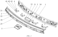
- FIG. 1 is an exploded view of a cowl top assembly of a vehicle according to an embodiment of the disclosure
- FIG. 2 is top view of the cowl top assembly of the vehicle according to an embodiment of the disclosure
- FIG. 3 is a front view of the cowl top assembly of the vehicle according to an embodiment of the disclosure
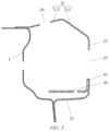
- FIG. 4 is a sectional view along line A-A in FIG. 3
- FIG. 5 is a sectional view along line B-B in FIG. 3
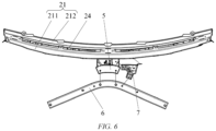
- FIG. 6 is an orientation diagram of a connection between the cowl top assembly of the vehicle and a Y-shaped support according to an embodiment of the disclosure
- FIG. 7 is an orientation diagram of a connection between the cowl top assembly of the vehicle and a drip rail assembly according to an embodiment of the disclosure
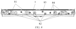
- FIG. 8 is a rear view of the cowl top assembly of the vehicle according to an embodiment of the disclosure.
- the cowl top assembly of the vehicle comprises a rear panel 1 and a front panel structure 2.
- the front panel structure 2 comprises a first top panel 21, a first vertical panel 22, and a first bottom panel 23 that are integrally formed.
- a front edge of the first top panel 21 and a front edge of the first bottom panel 23 are respectively connected to an upper edge and a lower edge of the first vertical panel 22, that is, the front panel structure is a structure with a substantially "C"-shaped longitudinal section, and a rear edge of the first top panel 21 and a rear edge of the first bottom panel 23 are connected to the rear panel 1, so that a cavity is enclosed by the rear panel 1 and the front panel structure 2.
- the first top panel 21 is shaped to be bent upwards along a transverse bending line in the middle of the first top panel, and the first top panel 21 is divided into a first section 211 and a second section 212 that are distributed front to rear.
- Four first collapsing holes 24 are formed in the second section 212, and four second collapsing holes 25 are formed in the first vertical panel 22. Both the first collapsing holes 24 and the second collapsing holes 25 are elongated holes.
- the four first collapsing holes 24 are distributed in the second section 212 in a width direction of the vehicle, and the four second collapsing holes 25 are distributed in the first vertical panel 22 in the width direction of the vehicle.
- a first reinforcing support 3 is provided in the cavity at a longitudinal central plane, and the first reinforcing support 3 comprises a second top panel 31, a second vertical panel 32, a second bottom panel 33, and two first side panels 34.
- a front edge of the second top panel 31 and a front edge of the second bottom panel 33 are respectively connected to an upper edge and a lower edge of the second vertical panel 32, and each of the two first side panels 34 is connected to a side edge of each of the second top panel 31, the second vertical panel 32 and the second bottom panel 33; and the second vertical panel 32 abuts against the first vertical panel 22, the second bottom panel 33 abuts against the first bottom panel 23, and a rear edge of the second top panel 31 and rear edges of the first side panels 34 abut against the rear panel 1.
- the four second reinforcing supports 4 are also provided in the cavity.
- the four second reinforcing supports 4 are distributed in the width direction of the vehicle and are uniformly distributed on two sides of the first reinforcing support 3.
- the second reinforcing support 4 comprises a third vertical panel 41, a third bottom panel 42, and two second side panels 43.
- a front edge of the third bottom panel 42 is connected to a lower edge of the third vertical panel 41, and each of the two second side panels 43 is connected to a side edge of each of the third vertical panel 41 and the third bottom panel 42; and the third vertical panel 41 abuts against the first vertical panel 22, and rear edges of the second side panels 43 abut against the rear panel 1. As shown in FIG.
- the cowl top assembly further comprises an aluminum-cast third reinforcing support 5.
- a first end of the third reinforcing support 5 is connected to the first bottom panel 23 at the longitudinal central plane, a second end of the third reinforcing support 5 is bolted to a Y-shaped support 6, and two branch ends of the Y-shaped support 6 are connected to two shock absorbers (not shown in the figure) of the vehicle.
- a drip rail assembly 8 of the vehicle is bolted to the first vertical panel 22 of the cowl top assembly.
- an instrument panel crossmember mounting hole 81, a cable harness mounting stud 82, an air conditioner mounting stud 83, and an interior trim mounting stud 84 are provided on a rear side of the rear panel 1.
- an instrument panel crossmember of the vehicle is bolted to the instrument panel crossmember mounting hole 81
- a cable harness bracket of the vehicle is fixed to the cable harness mounting stud 82
- an air conditioner bracket of the vehicle is fixed to the air conditioner mounting stud 83
- an interior trim mounting bracket is fixed to the interior trim mounting stud 84.
- the front panel structure 2 is configured as a structure with a substantially "C"-shaped longitudinal section
- the front panel structure 2 with the substantially “C”-shaped longitudinal section is connected to the rear panel 1 to enclose a cavity
- the first top panel 21 of the front panel structure 2 is shaped to be bent upwards along a transverse bending line in the middle of the first top panel
- the first top panel 21 is divided into a first section 211 and a second section 212 that are distributed front to rear
- a plurality of elongated first collapsing holes 24 distributed in the width direction of the vehicle are formed in the second section 212
- a plurality of elongated second collapsing holes 25 distributed in the width direction of the vehicle are formed in the first vertical panel 22 of the front panel structure 2, injuries to the pedestrians in pedestrian-vehicle collision accidents are effectively reduced.
- an impact force can be quickly transferred to the cowl top assembly, so that a rearward and obliquely downward acting force is exerted on the front panel structure 2 by the windshield with a lower edge supported at a junction between the first top panel 21 and the first vertical panel 22.
- the acting force is decomposed on the first top panel 21 and the first vertical panel 22, and then the first top panel 21 and the first vertical panel 22 are quickly and effectively collapsed for deformation at the first collapsing holes 24 and the second collapsing holes 25 respectively, thereby reducing the impact force on the pedestrian's head and effectively reducing injuries to the pedestrian.
- the cowl top assembly not only uses less material, and has a lighter weight, a short development cycle, and a lower cost, but also has a higher torsional resistance, and ensures a good NVH performance.
- the torsional strength of the cowl top assembly is further increased and the NVH performance is improved.
- the drip rail assembly 8 of the vehicle is connected to the first vertical panel 22, and the air conditioner bracket, the cable harness mounting bracket, the dashboard bracket and the interior trim mounting bracket of the vehicle are connected to the rear panel 1, so that a multi-point restraint is formed on the cowl top assembly without affecting the performance of the cowl top assembly to collapse to reduce injuries to the pedestrian, further increasing the torsional resistance of the cowl top assembly and improving the NVH performance.
- first collapsing holes 24 and four second collapsing holes 25 are provided, which is only a specific configuration and may be adjusted in a practical application so as to be adapted to different application scenarios.
- two, three, five or more first collapsing holes 24 and two, three, five or more second collapsing holes 25 are provided.
- the number of first collapsing holes 24 and the number of second collapsing holes 25 may be the same or different. It is a preferred way to configure the first collapsing holes 24 and the second collapsing holes 25 as elongated holes, which may be adjusted in a practical application so as to be adapted to different application scenarios.
- the first collapsing hole 24 may be a rectangular hole, an elliptical hole or another hole with a transverse dimension greater than a front-to-rear dimension, or a round hole, a square hole or other types of holes
- the second collapsing hole 25 may be a rectangular hole, an elliptical hole or another hole with a transverse dimension greater than a front-to-rear dimension, or a round hole, a square hole or other types of holes
- the first collapsing holes 24 and the second collapsing holes 25 may be the same or different in shape.
- first reinforcing support 3 may be configured in such a way that the rear edge of the second top panel 31, a rear edge of the second bottom panel 33 and the rear edges of the first side panels 34 all abut against the rear panel 1, or that one of the rear edge of the second top panel 31, the rear edge of the second bottom panel 33 and the rear edges of the first side panels 34 abuts against the rear panel 1.
- the second reinforcing support 4 may be configured in such a way that a rear edge of the second bottom panel 42 and a rear edge of the second side panel 43 both abut against the rear panel 1, or that only the rear edge of the second bottom panel 42 abuts against the rear panel 1.
- first top panel 21, the first vertical panel 22 and the first bottom panel 23 may also be separately formed and then connected together.
- the disclosure further provides a vehicle, comprising a cowl top assembly according to any of the above embodiments.
- vehicle may be an electric vehicle, a fuel vehicle, or a hybrid vehicle, etc.
Landscapes
- Engineering & Computer Science (AREA)
- Chemical & Material Sciences (AREA)
- Combustion & Propulsion (AREA)
- Transportation (AREA)
- Mechanical Engineering (AREA)
- Body Structure For Vehicles (AREA)
Claims (9)
- Verkleidungsoberteil für ein Fahrzeug, aufweisend eine Rückwand (1) und eine Vorderwandstruktur (2), wobeidie Vorderwandstruktur (2) eine erste obere Platte (21), eine erste vertikale Platte (22) und eine erste untere Platte (23) aufweist, und wobei eine Vorderkante der ersten oberen Platte (21) und eine Vorderkante der ersten unteren Platte (23) mit einer oberen Kante bzw. einer unteren Kante der ersten vertikalen Platte (22) verbunden sind und wobei eine Hinterkante der ersten oberen Platte (21) und eine Hinterkante der ersten unteren Platte (23) mit der Rückwand (1) verbunden sind, sodass ein Hohlraum durch die Rückwand (1) und die Vorderwandstruktur (2) eingeschlossen ist, underste Einfalllöcher (24) in der ersten oberen Platte (21) gebildet sind und zweite Einfalllöcher (25) in der ersten vertikalen Platte (22) gebildet sind,dadurch gekennzeichnet, dass ein erster Verstärkungsträger (3) im Hohlraum an einer längs verlaufenden mittleren Ebene bereitgestellt ist und dass der erste Verstärkungsträger (3) eine zweite obere Platte (31), eine zweite vertikale Platte (32), eine zweite untere Platte (33) und zwei erste seitliche Platten (34) aufweist,wobei eine Vorderkante der zweiten oberen Platte (31) und eine Vorderkante der zweiten unteren Platte (33) mit einer oberen Kante bzw. einer unteren Kante der zweiten vertikalen Platte (32) verbunden sind und wobei jede der zwei ersten seitlichen Platten (34) mit jeweils einer seitlichen Kante der zweiten oberen Platte (31), der zweiten vertikalen Platte (32) und der zweiten unteren Platte (33) verbunden ist, undwobei die zweite vertikale Platte (32) an die erste vertikale Platte (22) grenzt, die zweite untere Platte (33) an die erste untere Platte (23) grenzt und eine Hinterkante der zweiten oberen Platte (31), eine Hinterkante der zweiten unteren Platte (33) und/oder Hinterkanten der ersten seitlichen Platten (34) an die Rückwand (1) grenzen.
- Verkleidungsoberteil nach Anspruch 1, wobei die erste obere Platte (21), die erste vertikale Platte (22) und die erste untere Platte (23) integral ausgebildet sind.
- Verkleidungsoberteil nach Anspruch 1 oder 2, wobei die erste obere Platte (21) geformt ist, um entlang einer quer verlaufenden Biegelinie in der Mitte der ersten oberen Platte nach oben gebogen zu sein, wobei die erste obere Platte in einen ersten Abschnitt (211) und einen zweiten Abschnitt (212) geteilt ist, die von vorn nach hinten verteilt sind, und wobei die ersten Einfalllöcher (24) im zweiten Abschnitt (212) verteilt sind.
- Verkleidungsoberteil nach einem der Ansprüche 1 bis 3, wobei die ersten Einfalllöcher (211) und/oder die zweiten Einfalllöcher (212) jeweils eine quer verlaufende Abmessung aufweisen, die größer als eine Vorder-zu-Hinter-Abmessung davon ist.
- Verkleidungsoberteil nach einem der Ansprüche 1 bis 4, wobei mehrere zweite Verstärkungsträger (4) ebenfalls in dem Hohlraum bereitgestellt sind, wobei die mehreren zweiten Verstärkungsträger (4) in einer Breitenrichtung des Fahrzeugs verteilt sind und auf zwei Seiten des ersten Verstärkungsträgers (3) gleichförmig verteilt sind.
- Verkleidungsoberteil nach Anspruch 5, wobei der zweite Verstärkungsträger (4) eine dritte vertikale Platte (41), eine dritte untere Platte (42) und zwei zweite seitliche Platten (43) aufweist und wobei eine Vorderkante der dritten unteren Platte (42) mit einer unteren Kante der dritten vertikalen Platte (41) verbunden ist, und wobei jede der zwei zweiten seitlichen Platten (43) mit jeweils einer seitlichen Kante der dritten vertikalen Platte (41) und der dritten unteren Platte (42) verbunden ist, und
wobei die dritte vertikale Platte (41) an die erste vertikale Platte (22) grenzt und eine Hinterkante der dritten unteren Platte (42) und/oder Hinterkanten der zweiten seitlichen Platten (43) an die Rückwand grenzen. - Verkleidungsoberteil nach Anspruch 5 oder 6, wobei das Verkleidungsoberteil ferner einen dritten Verstärkungsträger (5) aufweist und wobei ein erstes Ende des dritten Verstärkungsträgers (5) mit der ersten unteren Platte (23) an der längs verlaufenden mittleren Ebene verbunden ist, und wobei ein zweites Ende des dritten Verstärkungsträgers (5) über eine Y-förmige Stütze (6) mit einem Stoßdämpfer des Fahrzeugs verbunden ist; und
wobei der dritte Verstärkungsträger (5) ein gegossenes Teil ist. - Verkleidungsoberteil nach einem der Ansprüche 5 bis 7, wobei eine Tropfschienenanordnung (8) des Fahrzeugs mit der ersten vertikalen Platte (22) verbunden ist, und/oder
wobei eine Klimaanlagenhalterung, eine Kabelbaummontagehalterung, eine Armaturenbretthalterung und/oder eine Innenverkleidungsmontagehalterung des Fahrzeugs mit der Rückwand verbunden sind. - Fahrzeug, aufweisend eine Verkleidungsoberteil eines Fahrzeugs nach einem der Ansprüche 1 bis 8.
Applications Claiming Priority (1)
| Application Number | Priority Date | Filing Date | Title |
|---|---|---|---|
| CN202210344119.5A CN114560015B (zh) | 2022-03-31 | 2022-03-31 | 车辆及其前围上盖板总成 |
Publications (2)
| Publication Number | Publication Date |
|---|---|
| EP4253200A1 EP4253200A1 (de) | 2023-10-04 |
| EP4253200B1 true EP4253200B1 (de) | 2024-06-05 |
Family
ID=81720244
Family Applications (1)
| Application Number | Title | Priority Date | Filing Date |
|---|---|---|---|
| EP23161721.8A Active EP4253200B1 (de) | 2022-03-31 | 2023-03-14 | Fahrzeug und stirnwandoberseite-anordnung dafür |
Country Status (3)
| Country | Link |
|---|---|
| US (1) | US20230312008A1 (de) |
| EP (1) | EP4253200B1 (de) |
| CN (1) | CN114560015B (de) |
Family Cites Families (10)
| Publication number | Priority date | Publication date | Assignee | Title |
|---|---|---|---|---|
| DE10037051A1 (de) * | 2000-07-29 | 2002-02-28 | Acts Gmbh & Co Kg | Kraftfahrzeug und Stoßfängeranordnung für ein Kraftfahrzeug |
| DE10221950A1 (de) * | 2002-05-13 | 2003-11-27 | Sai Automotive Sal Gmbh | Stirnwandmodul |
| JP5157353B2 (ja) * | 2007-01-22 | 2013-03-06 | 日産自動車株式会社 | 車両のカウル構造 |
| JP4490983B2 (ja) * | 2007-03-02 | 2010-06-30 | 本田技研工業株式会社 | 車両のフロントウインドシールド支持構造 |
| DE602008000247D1 (de) * | 2007-09-10 | 2009-12-10 | Honda Motor Co Ltd | Vorderteilkonstruktion eines Fahrzeuges |
| DE102010005834B4 (de) * | 2010-01-27 | 2025-05-22 | Bayerische Motoren Werke Aktiengesellschaft | Stützanordnung für eine Windschutzscheibe eines Personenkraftwagens |
| CN203473006U (zh) * | 2013-08-01 | 2014-03-12 | 一汽海马汽车有限公司 | 汽车发动机盖板 |
| CN209617278U (zh) * | 2019-02-02 | 2019-11-12 | 广州汽车集团股份有限公司 | 一种汽车前风窗横梁结构及车辆 |
| CN110696928B (zh) * | 2019-10-31 | 2021-02-19 | 东风汽车集团有限公司 | 一种基于行人头碰保护的前围上部结构 |
| CN217048798U (zh) * | 2022-03-31 | 2022-07-26 | 蔚来汽车科技(安徽)有限公司 | 车辆及其前围上盖板总成 |
-
2022
- 2022-03-31 CN CN202210344119.5A patent/CN114560015B/zh active Active
-
2023
- 2023-03-14 EP EP23161721.8A patent/EP4253200B1/de active Active
- 2023-03-27 US US18/190,463 patent/US20230312008A1/en not_active Abandoned
Also Published As
| Publication number | Publication date |
|---|---|
| CN114560015A (zh) | 2022-05-31 |
| EP4253200A1 (de) | 2023-10-04 |
| US20230312008A1 (en) | 2023-10-05 |
| CN114560015B (zh) | 2025-10-14 |
Similar Documents
| Publication | Publication Date | Title |
|---|---|---|
| CN107539370B (zh) | 前车身增强结构 | |
| CN115214790B (zh) | 汽车前机舱及汽车 | |
| JP2009083687A (ja) | 自動車の前部構造 | |
| US20160368535A1 (en) | Front vehicle body structure | |
| US9242676B2 (en) | Front vehicle body reinforcing structure | |
| CN115214789B (zh) | 下车身前部总成和汽车 | |
| CN206384041U (zh) | 仪表板横梁总成及汽车 | |
| CN111891224B (zh) | 前机舱结构和具有它的车辆 | |
| CN112046388B (zh) | 一种大灯支架及大灯安装定位结构 | |
| CN217994047U (zh) | 减震塔和车辆 | |
| EP4253200B1 (de) | Fahrzeug und stirnwandoberseite-anordnung dafür | |
| KR102933830B1 (ko) | 차량의 범퍼 | |
| JP4797704B2 (ja) | 車体前部構造 | |
| CN217048798U (zh) | 车辆及其前围上盖板总成 | |
| KR102905784B1 (ko) | 카울크로스바 조립체 | |
| JP2007230489A (ja) | 車体前部構造 | |
| KR20110136124A (ko) | 차량용 프런트 필라부 보강 구조 | |
| CN215553570U (zh) | 一种车身连接结构以及车辆 | |
| CN222905482U (zh) | 一种防撞梁结构、车身结构及汽车 | |
| CN219857002U (zh) | 用于安全气囊ecu的加强构造 | |
| CN217672467U (zh) | 通风饰板总成及车辆 | |
| KR101836515B1 (ko) | 차량의 카울 어셈블리 | |
| KR102879368B1 (ko) | 카울크로스바 조립체 | |
| KR101047990B1 (ko) | Nvh성능이 개선된 개단면 카울 구조 | |
| KR20020094740A (ko) | 자동차 리어 범퍼용 백 비임 |
Legal Events
| Date | Code | Title | Description |
|---|---|---|---|
| PUAI | Public reference made under article 153(3) epc to a published international application that has entered the european phase |
Free format text: ORIGINAL CODE: 0009012 |
|
| STAA | Information on the status of an ep patent application or granted ep patent |
Free format text: STATUS: EXAMINATION IS IN PROGRESS |
|
| 17P | Request for examination filed |
Effective date: 20230330 |
|
| AK | Designated contracting states |
Kind code of ref document: A1 Designated state(s): AL AT BE BG CH CY CZ DE DK EE ES FI FR GB GR HR HU IE IS IT LI LT LU LV MC ME MK MT NL NO PL PT RO RS SE SI SK SM TR |
|
| GRAP | Despatch of communication of intention to grant a patent |
Free format text: ORIGINAL CODE: EPIDOSNIGR1 |
|
| STAA | Information on the status of an ep patent application or granted ep patent |
Free format text: STATUS: GRANT OF PATENT IS INTENDED |
|
| GRAS | Grant fee paid |
Free format text: ORIGINAL CODE: EPIDOSNIGR3 |
|
| INTG | Intention to grant announced |
Effective date: 20240306 |
|
| GRAA | (expected) grant |
Free format text: ORIGINAL CODE: 0009210 |
|
| STAA | Information on the status of an ep patent application or granted ep patent |
Free format text: STATUS: THE PATENT HAS BEEN GRANTED |
|
| AK | Designated contracting states |
Kind code of ref document: B1 Designated state(s): AL AT BE BG CH CY CZ DE DK EE ES FI FR GB GR HR HU IE IS IT LI LT LU LV MC ME MK MT NL NO PL PT RO RS SE SI SK SM TR |
|
| REG | Reference to a national code |
Ref country code: CH Ref legal event code: EP |
|
| REG | Reference to a national code |
Ref country code: DE Ref legal event code: R096 Ref document number: 602023000131 Country of ref document: DE |
|
| REG | Reference to a national code |
Ref country code: IE Ref legal event code: FG4D |
|
| REG | Reference to a national code |
Ref country code: LT Ref legal event code: MG9D |
|
| PG25 | Lapsed in a contracting state [announced via postgrant information from national office to epo] |
Ref country code: BG Free format text: LAPSE BECAUSE OF FAILURE TO SUBMIT A TRANSLATION OF THE DESCRIPTION OR TO PAY THE FEE WITHIN THE PRESCRIBED TIME-LIMIT Effective date: 20240605 |
|
| REG | Reference to a national code |
Ref country code: NL Ref legal event code: MP Effective date: 20240605 |
|
| PG25 | Lapsed in a contracting state [announced via postgrant information from national office to epo] |
Ref country code: FI Free format text: LAPSE BECAUSE OF FAILURE TO SUBMIT A TRANSLATION OF THE DESCRIPTION OR TO PAY THE FEE WITHIN THE PRESCRIBED TIME-LIMIT Effective date: 20240605 Ref country code: HR Free format text: LAPSE BECAUSE OF FAILURE TO SUBMIT A TRANSLATION OF THE DESCRIPTION OR TO PAY THE FEE WITHIN THE PRESCRIBED TIME-LIMIT Effective date: 20240605 |
|
| PG25 | Lapsed in a contracting state [announced via postgrant information from national office to epo] |
Ref country code: GR Free format text: LAPSE BECAUSE OF FAILURE TO SUBMIT A TRANSLATION OF THE DESCRIPTION OR TO PAY THE FEE WITHIN THE PRESCRIBED TIME-LIMIT Effective date: 20240906 |
|
| PG25 | Lapsed in a contracting state [announced via postgrant information from national office to epo] |
Ref country code: ES Free format text: LAPSE BECAUSE OF FAILURE TO SUBMIT A TRANSLATION OF THE DESCRIPTION OR TO PAY THE FEE WITHIN THE PRESCRIBED TIME-LIMIT Effective date: 20240605 |
|
| PG25 | Lapsed in a contracting state [announced via postgrant information from national office to epo] |
Ref country code: LV Free format text: LAPSE BECAUSE OF FAILURE TO SUBMIT A TRANSLATION OF THE DESCRIPTION OR TO PAY THE FEE WITHIN THE PRESCRIBED TIME-LIMIT Effective date: 20240605 |
|
| PG25 | Lapsed in a contracting state [announced via postgrant information from national office to epo] |
Ref country code: NO Free format text: LAPSE BECAUSE OF FAILURE TO SUBMIT A TRANSLATION OF THE DESCRIPTION OR TO PAY THE FEE WITHIN THE PRESCRIBED TIME-LIMIT Effective date: 20240905 Ref country code: LV Free format text: LAPSE BECAUSE OF FAILURE TO SUBMIT A TRANSLATION OF THE DESCRIPTION OR TO PAY THE FEE WITHIN THE PRESCRIBED TIME-LIMIT Effective date: 20240605 Ref country code: HR Free format text: LAPSE BECAUSE OF FAILURE TO SUBMIT A TRANSLATION OF THE DESCRIPTION OR TO PAY THE FEE WITHIN THE PRESCRIBED TIME-LIMIT Effective date: 20240605 Ref country code: GR Free format text: LAPSE BECAUSE OF FAILURE TO SUBMIT A TRANSLATION OF THE DESCRIPTION OR TO PAY THE FEE WITHIN THE PRESCRIBED TIME-LIMIT Effective date: 20240906 Ref country code: FI Free format text: LAPSE BECAUSE OF FAILURE TO SUBMIT A TRANSLATION OF THE DESCRIPTION OR TO PAY THE FEE WITHIN THE PRESCRIBED TIME-LIMIT Effective date: 20240605 Ref country code: ES Free format text: LAPSE BECAUSE OF FAILURE TO SUBMIT A TRANSLATION OF THE DESCRIPTION OR TO PAY THE FEE WITHIN THE PRESCRIBED TIME-LIMIT Effective date: 20240605 Ref country code: BG Free format text: LAPSE BECAUSE OF FAILURE TO SUBMIT A TRANSLATION OF THE DESCRIPTION OR TO PAY THE FEE WITHIN THE PRESCRIBED TIME-LIMIT Effective date: 20240605 Ref country code: RS Free format text: LAPSE BECAUSE OF FAILURE TO SUBMIT A TRANSLATION OF THE DESCRIPTION OR TO PAY THE FEE WITHIN THE PRESCRIBED TIME-LIMIT Effective date: 20240905 |
|
| PG25 | Lapsed in a contracting state [announced via postgrant information from national office to epo] |
Ref country code: NL Free format text: LAPSE BECAUSE OF FAILURE TO SUBMIT A TRANSLATION OF THE DESCRIPTION OR TO PAY THE FEE WITHIN THE PRESCRIBED TIME-LIMIT Effective date: 20240605 |
|
| REG | Reference to a national code |
Ref country code: AT Ref legal event code: MK05 Ref document number: 1692281 Country of ref document: AT Kind code of ref document: T Effective date: 20240605 |
|
| PG25 | Lapsed in a contracting state [announced via postgrant information from national office to epo] |
Ref country code: NL Free format text: LAPSE BECAUSE OF FAILURE TO SUBMIT A TRANSLATION OF THE DESCRIPTION OR TO PAY THE FEE WITHIN THE PRESCRIBED TIME-LIMIT Effective date: 20240605 |
|
| PG25 | Lapsed in a contracting state [announced via postgrant information from national office to epo] |
Ref country code: PT Free format text: LAPSE BECAUSE OF FAILURE TO SUBMIT A TRANSLATION OF THE DESCRIPTION OR TO PAY THE FEE WITHIN THE PRESCRIBED TIME-LIMIT Effective date: 20241007 |
|
| PG25 | Lapsed in a contracting state [announced via postgrant information from national office to epo] |
Ref country code: PT Free format text: LAPSE BECAUSE OF FAILURE TO SUBMIT A TRANSLATION OF THE DESCRIPTION OR TO PAY THE FEE WITHIN THE PRESCRIBED TIME-LIMIT Effective date: 20241007 |
|
| PG25 | Lapsed in a contracting state [announced via postgrant information from national office to epo] |
Ref country code: PL Free format text: LAPSE BECAUSE OF FAILURE TO SUBMIT A TRANSLATION OF THE DESCRIPTION OR TO PAY THE FEE WITHIN THE PRESCRIBED TIME-LIMIT Effective date: 20240605 |
|
| PG25 | Lapsed in a contracting state [announced via postgrant information from national office to epo] |
Ref country code: EE Free format text: LAPSE BECAUSE OF FAILURE TO SUBMIT A TRANSLATION OF THE DESCRIPTION OR TO PAY THE FEE WITHIN THE PRESCRIBED TIME-LIMIT Effective date: 20240605 |
|
| PG25 | Lapsed in a contracting state [announced via postgrant information from national office to epo] |
Ref country code: AT Free format text: LAPSE BECAUSE OF FAILURE TO SUBMIT A TRANSLATION OF THE DESCRIPTION OR TO PAY THE FEE WITHIN THE PRESCRIBED TIME-LIMIT Effective date: 20240605 Ref country code: IS Free format text: LAPSE BECAUSE OF FAILURE TO SUBMIT A TRANSLATION OF THE DESCRIPTION OR TO PAY THE FEE WITHIN THE PRESCRIBED TIME-LIMIT Effective date: 20241005 |
|
| PG25 | Lapsed in a contracting state [announced via postgrant information from national office to epo] |
Ref country code: CZ Free format text: LAPSE BECAUSE OF FAILURE TO SUBMIT A TRANSLATION OF THE DESCRIPTION OR TO PAY THE FEE WITHIN THE PRESCRIBED TIME-LIMIT Effective date: 20240605 |
|
| PG25 | Lapsed in a contracting state [announced via postgrant information from national office to epo] |
Ref country code: RO Free format text: LAPSE BECAUSE OF FAILURE TO SUBMIT A TRANSLATION OF THE DESCRIPTION OR TO PAY THE FEE WITHIN THE PRESCRIBED TIME-LIMIT Effective date: 20240605 Ref country code: SK Free format text: LAPSE BECAUSE OF FAILURE TO SUBMIT A TRANSLATION OF THE DESCRIPTION OR TO PAY THE FEE WITHIN THE PRESCRIBED TIME-LIMIT Effective date: 20240605 |
|
| PG25 | Lapsed in a contracting state [announced via postgrant information from national office to epo] |
Ref country code: SM Free format text: LAPSE BECAUSE OF FAILURE TO SUBMIT A TRANSLATION OF THE DESCRIPTION OR TO PAY THE FEE WITHIN THE PRESCRIBED TIME-LIMIT Effective date: 20240605 |
|
| PG25 | Lapsed in a contracting state [announced via postgrant information from national office to epo] |
Ref country code: SM Free format text: LAPSE BECAUSE OF FAILURE TO SUBMIT A TRANSLATION OF THE DESCRIPTION OR TO PAY THE FEE WITHIN THE PRESCRIBED TIME-LIMIT Effective date: 20240605 Ref country code: SK Free format text: LAPSE BECAUSE OF FAILURE TO SUBMIT A TRANSLATION OF THE DESCRIPTION OR TO PAY THE FEE WITHIN THE PRESCRIBED TIME-LIMIT Effective date: 20240605 Ref country code: RO Free format text: LAPSE BECAUSE OF FAILURE TO SUBMIT A TRANSLATION OF THE DESCRIPTION OR TO PAY THE FEE WITHIN THE PRESCRIBED TIME-LIMIT Effective date: 20240605 Ref country code: PL Free format text: LAPSE BECAUSE OF FAILURE TO SUBMIT A TRANSLATION OF THE DESCRIPTION OR TO PAY THE FEE WITHIN THE PRESCRIBED TIME-LIMIT Effective date: 20240605 Ref country code: IS Free format text: LAPSE BECAUSE OF FAILURE TO SUBMIT A TRANSLATION OF THE DESCRIPTION OR TO PAY THE FEE WITHIN THE PRESCRIBED TIME-LIMIT Effective date: 20241005 Ref country code: EE Free format text: LAPSE BECAUSE OF FAILURE TO SUBMIT A TRANSLATION OF THE DESCRIPTION OR TO PAY THE FEE WITHIN THE PRESCRIBED TIME-LIMIT Effective date: 20240605 Ref country code: CZ Free format text: LAPSE BECAUSE OF FAILURE TO SUBMIT A TRANSLATION OF THE DESCRIPTION OR TO PAY THE FEE WITHIN THE PRESCRIBED TIME-LIMIT Effective date: 20240605 Ref country code: AT Free format text: LAPSE BECAUSE OF FAILURE TO SUBMIT A TRANSLATION OF THE DESCRIPTION OR TO PAY THE FEE WITHIN THE PRESCRIBED TIME-LIMIT Effective date: 20240605 |
|
| PG25 | Lapsed in a contracting state [announced via postgrant information from national office to epo] |
Ref country code: IT Free format text: LAPSE BECAUSE OF FAILURE TO SUBMIT A TRANSLATION OF THE DESCRIPTION OR TO PAY THE FEE WITHIN THE PRESCRIBED TIME-LIMIT Effective date: 20240605 |
|
| REG | Reference to a national code |
Ref country code: DE Ref legal event code: R097 Ref document number: 602023000131 Country of ref document: DE |
|
| PLBE | No opposition filed within time limit |
Free format text: ORIGINAL CODE: 0009261 |
|
| STAA | Information on the status of an ep patent application or granted ep patent |
Free format text: STATUS: NO OPPOSITION FILED WITHIN TIME LIMIT |
|
| PG25 | Lapsed in a contracting state [announced via postgrant information from national office to epo] |
Ref country code: DK Free format text: LAPSE BECAUSE OF FAILURE TO SUBMIT A TRANSLATION OF THE DESCRIPTION OR TO PAY THE FEE WITHIN THE PRESCRIBED TIME-LIMIT Effective date: 20240605 |
|
| 26N | No opposition filed |
Effective date: 20250306 |
|
| PG25 | Lapsed in a contracting state [announced via postgrant information from national office to epo] |
Ref country code: SE Free format text: LAPSE BECAUSE OF FAILURE TO SUBMIT A TRANSLATION OF THE DESCRIPTION OR TO PAY THE FEE WITHIN THE PRESCRIBED TIME-LIMIT Effective date: 20240605 |
|
| PG25 | Lapsed in a contracting state [announced via postgrant information from national office to epo] |
Ref country code: MC Free format text: LAPSE BECAUSE OF FAILURE TO SUBMIT A TRANSLATION OF THE DESCRIPTION OR TO PAY THE FEE WITHIN THE PRESCRIBED TIME-LIMIT Effective date: 20240605 |
|
| PG25 | Lapsed in a contracting state [announced via postgrant information from national office to epo] |
Ref country code: LU Free format text: LAPSE BECAUSE OF NON-PAYMENT OF DUE FEES Effective date: 20250314 |
|
| REG | Reference to a national code |
Ref country code: BE Ref legal event code: MM Effective date: 20250331 |
|
| PG25 | Lapsed in a contracting state [announced via postgrant information from national office to epo] |
Ref country code: BE Free format text: LAPSE BECAUSE OF NON-PAYMENT OF DUE FEES Effective date: 20250331 |
|
| PG25 | Lapsed in a contracting state [announced via postgrant information from national office to epo] |
Ref country code: IE Free format text: LAPSE BECAUSE OF NON-PAYMENT OF DUE FEES Effective date: 20250314 |
|
| PGFP | Annual fee paid to national office [announced via postgrant information from national office to epo] |
Ref country code: DE Payment date: 20260319 Year of fee payment: 4 |
|
| PGFP | Annual fee paid to national office [announced via postgrant information from national office to epo] |
Ref country code: FR Payment date: 20260323 Year of fee payment: 4 |