EP4253210B1 - Système d'anneau de levage de frein - Google Patents
Système d'anneau de levage de frein Download PDFInfo
- Publication number
- EP4253210B1 EP4253210B1 EP23166342.8A EP23166342A EP4253210B1 EP 4253210 B1 EP4253210 B1 EP 4253210B1 EP 23166342 A EP23166342 A EP 23166342A EP 4253210 B1 EP4253210 B1 EP 4253210B1
- Authority
- EP
- European Patent Office
- Prior art keywords
- brake
- lift ring
- decoupler
- brake lift
- guide structure
- Prior art date
- Legal status (The legal status is an assumption and is not a legal conclusion. Google has not performed a legal analysis and makes no representation as to the accuracy of the status listed.)
- Active
Links
Images



Classifications
-
- B—PERFORMING OPERATIONS; TRANSPORTING
- B62—LAND VEHICLES FOR TRAVELLING OTHERWISE THAN ON RAILS
- B62L—BRAKES SPECIALLY ADAPTED FOR CYCLES
- B62L3/00—Brake-actuating mechanisms; Arrangements thereof
- B62L3/06—Means for locking the actuating mechanisms
-
- B—PERFORMING OPERATIONS; TRANSPORTING
- B60—VEHICLES IN GENERAL
- B60T—VEHICLE BRAKE CONTROL SYSTEMS OR PARTS THEREOF; BRAKE CONTROL SYSTEMS OR PARTS THEREOF, IN GENERAL; ARRANGEMENT OF BRAKING ELEMENTS ON VEHICLES IN GENERAL; PORTABLE DEVICES FOR PREVENTING UNWANTED MOVEMENT OF VEHICLES; VEHICLE MODIFICATIONS TO FACILITATE COOLING OF BRAKES
- B60T11/00—Transmitting braking action from initiating means to ultimate brake actuator without power assistance or drive or where such assistance or drive is irrelevant
- B60T11/04—Transmitting braking action from initiating means to ultimate brake actuator without power assistance or drive or where such assistance or drive is irrelevant transmitting mechanically
- B60T11/043—Transmitting braking action from initiating means to ultimate brake actuator without power assistance or drive or where such assistance or drive is irrelevant transmitting mechanically in case of steerable wheels
-
- B—PERFORMING OPERATIONS; TRANSPORTING
- B60—VEHICLES IN GENERAL
- B60T—VEHICLE BRAKE CONTROL SYSTEMS OR PARTS THEREOF; BRAKE CONTROL SYSTEMS OR PARTS THEREOF, IN GENERAL; ARRANGEMENT OF BRAKING ELEMENTS ON VEHICLES IN GENERAL; PORTABLE DEVICES FOR PREVENTING UNWANTED MOVEMENT OF VEHICLES; VEHICLE MODIFICATIONS TO FACILITATE COOLING OF BRAKES
- B60T11/00—Transmitting braking action from initiating means to ultimate brake actuator without power assistance or drive or where such assistance or drive is irrelevant
- B60T11/04—Transmitting braking action from initiating means to ultimate brake actuator without power assistance or drive or where such assistance or drive is irrelevant transmitting mechanically
- B60T11/046—Using cables
-
- B—PERFORMING OPERATIONS; TRANSPORTING
- B60—VEHICLES IN GENERAL
- B60T—VEHICLE BRAKE CONTROL SYSTEMS OR PARTS THEREOF; BRAKE CONTROL SYSTEMS OR PARTS THEREOF, IN GENERAL; ARRANGEMENT OF BRAKING ELEMENTS ON VEHICLES IN GENERAL; PORTABLE DEVICES FOR PREVENTING UNWANTED MOVEMENT OF VEHICLES; VEHICLE MODIFICATIONS TO FACILITATE COOLING OF BRAKES
- B60T11/00—Transmitting braking action from initiating means to ultimate brake actuator without power assistance or drive or where such assistance or drive is irrelevant
- B60T11/04—Transmitting braking action from initiating means to ultimate brake actuator without power assistance or drive or where such assistance or drive is irrelevant transmitting mechanically
- B60T11/06—Equalising arrangements
-
- B—PERFORMING OPERATIONS; TRANSPORTING
- B60—VEHICLES IN GENERAL
- B60T—VEHICLE BRAKE CONTROL SYSTEMS OR PARTS THEREOF; BRAKE CONTROL SYSTEMS OR PARTS THEREOF, IN GENERAL; ARRANGEMENT OF BRAKING ELEMENTS ON VEHICLES IN GENERAL; PORTABLE DEVICES FOR PREVENTING UNWANTED MOVEMENT OF VEHICLES; VEHICLE MODIFICATIONS TO FACILITATE COOLING OF BRAKES
- B60T7/00—Brake-action initiating means
- B60T7/02—Brake-action initiating means for personal initiation
- B60T7/08—Brake-action initiating means for personal initiation hand actuated
- B60T7/10—Disposition of hand control
-
- B—PERFORMING OPERATIONS; TRANSPORTING
- B62—LAND VEHICLES FOR TRAVELLING OTHERWISE THAN ON RAILS
- B62J—CYCLE SADDLES OR SEATS; AUXILIARY DEVICES OR ACCESSORIES SPECIALLY ADAPTED TO CYCLES AND NOT OTHERWISE PROVIDED FOR, e.g. ARTICLE CARRIERS OR CYCLE PROTECTORS
- B62J11/00—Supporting arrangements specially adapted for fastening specific devices to cycles, e.g. supports for attaching maps
- B62J11/10—Supporting arrangements specially adapted for fastening specific devices to cycles, e.g. supports for attaching maps for mechanical cables, hoses, pipes or electric wires, e.g. cable guides
- B62J11/13—Supporting arrangements specially adapted for fastening specific devices to cycles, e.g. supports for attaching maps for mechanical cables, hoses, pipes or electric wires, e.g. cable guides specially adapted for mechanical cables
-
- B—PERFORMING OPERATIONS; TRANSPORTING
- B62—LAND VEHICLES FOR TRAVELLING OTHERWISE THAN ON RAILS
- B62K—CYCLES; CYCLE FRAMES; CYCLE STEERING DEVICES; RIDER-OPERATED TERMINAL CONTROLS SPECIALLY ADAPTED FOR CYCLES; CYCLE AXLE SUSPENSIONS; CYCLE SIDECARS, FORECARS, OR THE LIKE
- B62K21/00—Steering devices
- B62K21/12—Handlebars; Handlebar stems
-
- B—PERFORMING OPERATIONS; TRANSPORTING
- B62—LAND VEHICLES FOR TRAVELLING OTHERWISE THAN ON RAILS
- B62L—BRAKES SPECIALLY ADAPTED FOR CYCLES
- B62L3/00—Brake-actuating mechanisms; Arrangements thereof
- B62L3/02—Brake-actuating mechanisms; Arrangements thereof for control by a hand lever
Definitions
- the invention relates to a brake stroke ring system for transmitting a brake stroke caused by a driver to a brake system of a vehicle with the features of claim 1.
- a steering system is known from BMX bicycles which allows a rotational decoupling of the brake cables.
- BMX bicycles which allows a rotational decoupling of the brake cables.
- Such systems are known, for example, from the US4653768A , JP1987247989A , US4770435A and the US5992869A .
- the JP2009173162A describes a solution in which a ring-shaped, non-rotating brake lever is arranged under a circular steering wheel. Due to the circular shape of the brake lever, the brake cables can be operated from any angle, regardless of how far the steering wheel is turned.
- the proposed solution is complicated in its construction and requires a large number of components.
- a lever guide is provided below the brake lever, which supports the brake lever.
- the circumference of the brake lever does not completely follow the steering wheel movement, since only a partial circle rotation is possible due to the design using the lever guide. This can be perceived as annoying by a driver if his palms rest on the steering wheel and follow the movement of the steering wheel and the fingers that contact the brake lever drag on the brake lever.
- the proposed construction is voluminous, which disadvantageously requires a lot of space is taken up and it is also prone to maintenance due to its complex design.
- the means that is operated by a driver to carry out the braking process should be freely rotatable about the longitudinal axis of the steering wheel axis.
- a system or device should be provided whose simple construction allows a compact design.
- the invention can be used to ensure that a vehicle can be braked while cornering by providing a means, in particular a brake lifting ring (3.0), which is operated by a driver to carry out the braking process and is designed to be freely rotatable about the longitudinal axis of the handlebar axis.
- the brake lifting ring can move freely about the longitudinal axis of the handlebar axis, so that the driver's fingers do not drag on the brake lifting ring when the handlebar rotates.
- the system allows a compact design in which no additional support structure is required.
- the invention relates to a brake stroke ring system (1.0) for transmitting a brake stroke caused by a driver to a brake system of a vehicle comprising a vehicle frame, wherein the system comprises a brake stroke ring which is designed to is designed to be pulled by a driver of the vehicle in the direction of a steering wheel, wherein the brake lift ring is arranged around a handlebar axis, wherein the brake lift ring system is characterized in that the brake lift ring is connected or connectable to a brake lift ring guide structure, wherein the brake lift ring guide structure is arranged to be axially displaceable along the handlebar axis and radially rotatable about the handlebar axis.
- the vehicle according to the invention can be driven by a driver using muscle power, preferably via pedals.
- the vehicle can comprise at least three wheels (tricycle).
- a braking system is arranged on the axle of at least two wheels, preferably wheels that are arranged opposite one another on the same axle.
- a braking system is used such as that found on bicycles, for example. Examples include disc brakes, rim brakes, V-brakes, cantilever brakes, U-brakes, and side-pull brakes.
- a braking process is triggered by a braking stroke by the driver.
- a braking stroke requires the driver to apply braking force.
- the braking force is preferably transmitted to the braking system via a cable, which is also known as a Bowden cable.
- the Bowden cable essentially consists of a thin steel cable that is covered by a pressure-resistant outer casing.
- the vehicle comprises a steering wheel (2.1) which is arranged at one end of a steering axle (2.2), wherein the steering axle is rotatably mounted in a vehicle frame (2.0) and can rotate about its own axis.
- the vehicle frame is understood here to be the structure supporting the steering axle.
- the steering wheel can be designed with a closed, for example circular, circumference on which the driver can turn the steering wheel and the steering axle connected to it.
- wheel-shaped steering wheels instead of wheel-shaped steering wheels, however, other shapes of steering wheels can also be provided which allow rotation of the steering axle for steering the vehicle.
- the brake lift ring system also includes a brake lift ring (3.0) that has the same center axis as the steering wheel and is arranged behind the steering wheel so that the driver can grip the brake lift ring with his fingers while the palms and/or thumbs are in contact with the steering wheel. This advantageously means that the driver does not have to take his hands off the steering wheel to brake.
- the brake stroke ring is connected or connectable to a brake stroke ring guide structure (3.1).
- this is preferably a form-fitting or material-fitting connection.
- the brake stroke guide structure and the brake stroke ring can be connected to one another in a form-fitting and reversible manner using a click or snap mechanism, whereby the connection can be released by pressing a button on the click or snap mechanism.
- the brake stroke ring and the brake stroke ring guide structure can be welded together, which advantageously creates a stable connection that is resistant to vibrations when used as intended.
- the brake lift ring guide structure like the brake lift ring, is axially displaceable along the handlebar axis and radially rotatable about it, with the axial displacement being limited by the position of the steering wheel in one direction and by the vehicle frame in the other direction.
- Radially rotatable means rotatable in the circumferential direction of the handlebar axis around the handlebar axis.
- the brake stroke ring guide structure comprises an elongated ring element (3.5) which is screwed to the brake stroke ring, thereby providing an axial and radial positive connection.
- Inside the ring element in the side of the ring element facing the vehicle frame, at least two threaded holes are arranged, into which rod elements (3.6) can be placed, which can be connected to a decoupler described further below.
- the axial displaceability of the brake stroke ring and the associated axial displacement of the brake stroke ring guide structure is essential to the invention in order to transmit the braking force required for braking to the braking system.
- the brake lift ring guide structure is designed such that it is not radially rotatable about the handlebar axis. This can be achieved, for example, by arranging longitudinal grooves and/or longitudinal springs along the handlebar axis longitudinal axis and the longitudinal axis of the brake lift ring guide structure, wherein these are designed so that the brake lift ring guide structure is guided in a rail-like manner along the handlebar axis.
- the brake stroke ring guide structure is connected or connectable to a decoupler, wherein the decoupler comprises a first decoupler half and a second decoupler half.
- a decoupler (4.0) is understood here to be an element which is designed not to transmit a radial rotation exerted on a first side of the decoupler to a second side of the decoupler opposite the first side, while an axial displacement is transmitted. What is relevant here is that an axial displacement is transmitted in both axial directions.
- a decoupler according to the invention comprises a first decoupler half (4.1), which represents the first side, and a second decoupler half (4.2), which represents the second side.
- the first decoupler half is arranged proximal to the steering wheel, which means that it is arranged closer to the steering wheel than the second decoupler half, which is thus arranged distal to the steering wheel.
- the brake stroke ring guide structure is preferably connected to the first decoupler half (4.1), so that the brake stroke ring guide structure overcomes a distance between the brake stroke ring and the decoupler (4.0).
- the brake stroke ring guide structure (3.1) can advantageously be designed to be very compact, particularly close to the handlebar axis.
- the handlebar can therefore advantageously be designed to be very thin in the upper area.
- a compact structure also creates space for other elements, such as a display.
- the first decoupler half (4.1) thus has only one degree of freedom compared to the second decoupler half (4.2), this degree of freedom being rotation around the handlebar axis.
- There is therefore a positive connection such that an axial displacement of the first decoupler half by a certain distance in a first direction, parallel to the handlebar axis, also results in a displacement of the second decoupler half by the same distance in this first direction and that an axial displacement of the first decoupler half by a certain distance in a second direction opposite to the first direction also results in a displacement of the second decoupler half by the same distance in this second direction.
- the first decoupler half and the second decoupler half advantageously support each other and the device can therefore be designed to be very compact even without a support structure.
- the brake ring guide structure is designed such that it runs parallel to the handlebar axis at least in sections, wherein the brake ring guide structure, which is preferably designed in sections as a hollow cylinder, i.e. has a hollow cylindrical section, encloses the handlebar axis in such a way that the brake ring guide structure is guided, which advantageously prevents the brake ring guide structure from jamming or tilting relative to the handlebar axis.
- the handlebar axis is arranged in the hollow cylindrical section of the brake ring guide structure.
- the space between the handlebar axis and the hollow cylindrical section of the brake ring guide structure is designed such that that the brake ring guide structure can slide on the handlebar axis both radially and axially, but tilting is prevented.
- the axis of symmetry which runs within the hollow cylindrical section, always remains parallel to the axis of symmetry of the handlebar axis.
- the axis of symmetry of the handlebar axis and the axis of symmetry of the hollow cylindrical section of the brake ring guide structure coincide.
- tilting of a hollow cylindrical section of a brake ring guide structure can be prevented, for example, by the inside of the hollow cylindrical section of the brake ring guide structure being a small distance from the outside of the handlebar axis in this section, wherein the inside diameter of the hollow cylindrical section is preferably a maximum of 110%, particularly preferably a maximum of 105%, very particularly preferably a maximum of 102% of the outside diameter of the handlebar axis.
- spacers can be arranged between the hollow cylindrical section of the brake ring guide structure and the outside of the handlebar axis.
- a larger distance can also be compensated by such spacers, in particular by friction-reducing elements, for example by friction-reducing bearing elements, as described herein. Tilting can therefore also be prevented by filling the resulting cavity between the inside of the hollow cylindrical section of the brake ring guide structure and the outside of the handlebar axis with spacers, in particular by friction-reducing bearing elements.
- a hollow-cylindrical section can also have openings. It is relevant that the hollow-cylindrical section of the brake ring guide structure delimits the handlebar axis from at least two or at least three sides, so that an axial displacement and also a rotation of the hollow-cylindrical section of the brake ring guide structure on the handlebar axis is possible. Optionally, however, the hollow-cylindrical section does not have any openings.
- the first decoupler half comprises an annular element
- the second decoupler half comprises an annular element with a circumferential recess with a raised edge in which the first decoupler half is mounted so as to be radially rotatable.
- the raised edge ensures that an axial displacement of the first decoupler half caused by the brake ring guide structure is transmitted to the second decoupler half, whereby the latter also carries out an axial displacement but is rotationally decoupled from the first decoupler half.
- the rod elements described above are designed to connect the brake stroke ring guide structure to the first decoupler half.
- a rod element can be connected to the first decoupler half, or the brake stroke ring guide structure to the first decoupler half, using a connecting means freely selectable by the person skilled in the art. This advantageously means that the brake stroke ring guide structure can be quickly separated from the decoupler, which is particularly advantageous during maintenance work.
- the brake stroke ring guide structure is or can be connected to the first decoupler half in an axially positive and radially positive manner, with the first decoupler half being arranged to be axially displaceable along the handlebar axis and radially rotatable about the handlebar axis.
- An axial positive connection between two components e.g. the brake stroke ring guide structure and the first decoupler half
- a radial positive connection between two components is understood to mean that they are connected to one another in such a way that both components are forced to exert the same radial rotation.
- connection of the brake stroke ring guide structure to the first decoupler half can be set up to be reversible (connectable).
- a reversible axial and radial positive connection can be achieved, for example, by screwing the brake stroke ring guide structure to the first decoupler half.
- This advantageously makes it easy to maintain and clean the individual components, in particular the brake stroke ring guide structure and the first decoupler half as well as the second decoupler half.
- the brake stroke ring guide structure can be welded to the first decoupler half, or the material of these two components can form the same continuity and be produced, for example, in a casting process.
- the first decoupler half is connected or connectable to the second decoupler half in an axially positively locking manner.
- a connection if it is intended to allow radial rotation of the first decoupler half against the second decoupler half, can of course not be achieved via a materially locking connection, but rather via a positively locking connection, the axial positive locking in this embodiment being provided by the raised edge of the annular element of the second decoupler half enclosing the annular element of the first decoupler half in a positively locking manner.
- the second decoupler half can be designed in such a way that it consists of two ring-shaped elements that can be reversibly connected to one another via a thread and each have a raised edge running around the circumference, and when connected form the circumferential recess in which the ring-shaped element of the first decoupler half is mounted so that it can rotate radially.
- the second decoupler half is axially displaceable along the steering axis and is arranged radially statically in relation to the vehicle frame, with the first decoupler half being mounted radially rotatably against the second decoupler half.
- a radially static arrangement means that the second decoupler half does not perform any radial rotation.
- the first decoupler half is mounted radially rotatably in the second decoupler half. This means that the first decoupler half follows the radial rotation of the brake ring guide structure.
- the second decoupler half is preferably coupled to at least one brake cable means (5.0), wherein the brake cable means is designed to transmit the braking stroke to the braking system.
- a brake cable means can be a cable pull or Bowden cable or any other means that is suitable for transmitting the braking stroke from the second decoupler half to the braking system.
- a coupling is understood here to mean a reversible connection of a component to another component, which is preferably designed for a tensile load.
- the person skilled in the art can select a suitable connection (e.g. clamping, screwing) to connect the brake cable means to the second decoupler half.
- one end of the brake cable means is designed as a thickened portion that is inserted into eyelets in the second decoupler half.
- the second decoupler half is coupled to at least one brake lever (5.1), wherein the brake lever is coupled to the brake cable means.
- a brake lever according to the invention can be a brake lever such as that known from US6443027B1 is known. Other similarly designed brake levers are known to the person skilled in the art.
- the brake lever can be connected to the brake cable means or the second decoupler half by a means selected by the person skilled in the art.
- the brake lever contacts a circumferential contact surface of the brake stroke ring guide structure with a proximal brake lever end in a point-like manner, whereby the proximal brake lever end is adapted to follow the axial displacement of the brake stroke ring guide structure.
- the proximal brake lever end (5.2) is understood to mean the part of the brake lever which contacts the circumferential contact surface of the brake stroke ring guide structure, wherein a point-like contact is provided by the proximal brake lever end being designed, for example, spherically.
- the circumferential contact surface (3.2) of the brake stroke ring guide structure is a surface arranged on the outer circumference of the brake stroke ring guide structure.
- the proximal brake lever end In order for the proximal brake lever end to be able to follow an axial displacement of the brake stroke ring guide structure, the latter is designed in such a way that the side of the circumferential contact surface that is oriented closer to the vehicle frame is designed, for example, as a raised edge, so that when the brake lever guide structure is axially displaced, the raised edge presses against the proximal brake lever end and the latter thus follows the axial displacement of the brake lever guide structure.
- the circumferential contact surface of the brake stroke ring guide structure comprises a circumferential guide groove (3.3) which is designed to guide the proximal brake lever end.
- the width of the circumferential guide groove is preferably selected such that it corresponds to the diameter of a spherical proximal brake lever end.
- the depth of the circumferential guide groove can correspond to at least one tenth, preferably at least one fifth and very particularly preferably at least one third of the diameter of a proximal brake lever end.
- the handlebar axis and/or the contact surface of the brake stroke ring guide structure and/or the circumferential guide groove and/or an inner side of the brake stroke ring guide structure comprises at least one friction-reducing bearing element.
- the inner side of the brake stroke ring guide structure (3.4) is understood to mean the surface of the brake stroke ring guide structure which faces the handlebar axis and contacts it, provided that no friction-reducing bearing element is arranged.
- a friction-reducing bearing element (6.0) is understood to mean a means that is designed to cause the lowest possible friction between two components (e.g. the inside of the brake stroke ring guide structure and the handlebar axis).
- the friction-reducing means can be made of a plastic (e.g.
- Polytetrafluoroethylene polytetrafluoroethylene
- self-lubricating plastic e.g., polytetrafluoroethylene
- self-lubricating plastic e.g., polytetrafluoroethylene
- a friction-reducing bearing element advantageously reduces the wear of components that come into contact with one another. Another advantage is that it prevents annoying squeaking.
- the friction-reducing bearing element is designed to provide a point-like contact surface between the inside of the brake stroke ring guide structure and the handlebar axle.
- a point-like contact surface can be achieved, for example, by means of knob-like elevations in the surface of the handlebar axle or in the inside of the brake stroke ring guide structure.
- a point-shaped contact surface advantageously reduces the friction between the inside of the brake stroke ring guide structure and the handlebar axis and thus the wear.
- the friction-reducing bearing element is formed from at least three ball bearings (6.2), which are spaced apart from one another around the circumference of the handlebar axis concentrically to the handlebar axis at an angle of 120°. Such an arrangement is referred to as a ball bearing pair.
- the friction-reducing bearing element preferably comprises at least two ball bearing pairs, which are arranged spaced apart from one another along the handlebar axis. The expert can freely determine the suitable position on the handlebar axis.
- the proximal brake lever end comprises a ball bearing which is designed to provide a point-shaped contact surface between the proximal brake lever end and the contact surface of the brake lifting ring guide structure or the circumferential guide groove. This can advantageously reduce the friction between the proximal brake lever end and the contact surface of the brake lifting ring guide structure.
- the system according to the invention comprises a locking means which is designed to reversibly fix the brake lifting ring to the handlebar after the braking stroke has taken place.
- a locking means (2.3) is arranged either on the brake lifting ring or on the steering wheel and can be operated by the driver in such a way that the brake lifting ring is reversibly connected to the steering wheel in an axially positive-locking manner after the braking stroke has taken place, i.e. when the distance between the brake lifting ring and the steering wheel is minimal.
- This can advantageously be used to implement a parking brake. If the driver wants to move the vehicle again, he can flip the locking means back over and release the brake lifting ring from the steering wheel again.
- the locking means is designed in such a way that a radial positive connection is also provided between the brake lifting ring and the steering wheel.
- the locking means can comprise a lock, so that the vehicle is advantageously secured against theft.
- the invention also encompasses the use of a brake stroke ring system (as defined herein) in a vehicle, in particular in a multi-track bicycle, for transmitting a brake stroke caused by a rider.
- the Fig. 1 shows a schematic representation of an embodiment of the brake stroke ring system (1.0) in the non-actuated state ( Fig. 1A ) and in the actuated state with the brake stroke completed ( Fig. 1B ).
- the driver who controls the vehicle via the steering wheel (2.1) , pulls on the brake stroke ring (3.0) to initiate a brake stroke.
- the brake stroke ring (3.0) is radially rotatable around the steering wheel axis (2.2) in a clockwise and anti-clockwise direction (indicated by the rotation arrows).
- the brake stroke ring (3.0) is connected to a brake stroke ring guide structure (3.1) , whereby this connection is reversible by means not shown. This connection is designed in such a way that the
- the brake stroke ring guide structure (3.1) is at least partially hollow-cylindrical in shape, with the brake stroke ring guide structure (3.1) enclosing the handlebar axis (2.2).
- the hollow-cylindrical section of the brake stroke ring guide structure (3.1) is the section of the brake stroke ring guide structure (3.1) that runs parallel to the handlebar axis (2.2).
- the inside of the hollow-cylindrical section of the brake ring guide structure (3.1) rests against the outside of the handlebar axis (2.2).
- Both components can be moved axially along the handlebar axis (2.2) (indicated by the double arrow) and can be rotated radially about the handlebar axis (2.2) .
- the brake ring guide structure (3.1) is connected to a decoupler (4.0) .
- This has a first decoupler half (4.1) and a second decoupler half (4.2) , whereby the first decoupler half (4.1) is oriented proximally to the steering wheel (2.1) and the second decoupler half (4.2) is oriented distally to the steering wheel (2.1) .
- the interaction of the first decoupler half (4.1) and the second decoupler half (4.2) is shown in a highly simplified manner in this figure, but the decoupler (4.0) is set up in such a way that it allows a radial rotation of the first decoupler half (4.1) , whereby the radial rotation is decoupled by the decoupler (4.0) .
- the second decoupler half (4.2) is arranged radially statically, but an axial displacement of the first decoupler half (4.1) is transmitted to the second decoupler half (4.2) .
- a braking stroke caused by a driver is transmitted to the brake lever (5.1) , which is connected to the second decoupler half (4.2) via a brake cable (5.0), here a Bowden cable.
- the brake lever (5.1) is also connected to a braking system of the vehicle (not shown ) via a brake cable (5.0) .
- the brake lever (5.1) advantageously enables adjustable force conversion, so that the force transmission of the braking stroke to the braking system is adjustable.
- the brake cable (5.0) can also be connected directly to the braking system of the vehicle from the second decoupler half (4.2) in order to actuate it.
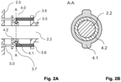
- the Fig. 2A shows a representation of an embodiment of a decoupler (4.0) made of a metal (e.g. aluminum, steel).
- a decoupler (4.0) made of a metal (e.g. aluminum, steel).
- This comprises a first decoupler half (4.1), which is rotatably mounted in the second decoupler half (4.2) .
- the second decoupler half (4.2) can be understood as a female ring in which the first decoupler half (4.1) is rotatably mounted about the handlebar axis (2.2) .
- the illustration also shows how a brake cable means (5.0), e.g. a Bowden cable, is coupled to the second decoupler half (4.2) .
- the brake stroke ring guide structure (3.1), not shown here, is reversibly connected to a ring element (3.5) .
- the ring element (3.5) has threaded holes for receiving a rod element (3.6) .
- the rod elements (3.6) are reversibly connected to the first decoupler half (4.1) via a connecting means (3.7) . If necessary, the connecting means (3.7) allows the rod elements (3.6) to be separated and thus the brake stroke ring guide structure (3.1) to be decoupled from the decoupler (4.0). This advantageously means that the brake stroke ring guide structure (3.1) can be easily removed from the decoupler (4.0) , which is necessary, for example, during maintenance work.
- the Fig. 2B shows a cross-sectional view through the decoupler (4.0) along the section plane AA from Fig. 2A .
- the second decoupler half (4.2) is made of a low-friction, slippery plastic, or at least coated with it. This advantageously ensures that the second decoupler half (4.2) is mounted on the handlebar axle (2.2) with low friction on the one hand, and the first decoupler half (4.1) is mounted in the second decoupler half (4.2) with low friction on the other hand.
- the Fig. 3A and 3B shows a schematic representation of an embodiment of the brake stroke ring system (1.0) in the non-actuated state ( Fig. 3A ) and in the actuated state with the brake stroke completed ( Fig.
- the brake stroke ring guide structure (1.0) is designed in such a way that it has a circumferential contact surface (3.2)
- the circumferential contact surface has a guide groove (3.3) in which at least one brake lever (5.1), in particular its proximal brake lever end (5.2), is mounted in a guideable manner by making point-like contact with the guide groove (3.3 ).
- the guide groove (3.3) is preferably coated with a friction-reducing bearing element (not shown), here a sliding plastic (e.g. polytetrafluoroethylene), in order to guide the proximal brake lever end with less friction and thus advantageously reduce its wear.
- the Fig. 4A and 4B shows a circumferential contact surface (3.2) with the circumferential guide groove (3.3) and a brake lever (5.1 ) mounted in the guide groove (3.3 ) in a longitudinal cross section to the handlebar axis (2.2) ( Fig. 4A ) and in an oblique view ( Fig. 4B ).
- the circumferential guide groove (3.3) is coated with a friction-reducing bearing element (6.0) .
- the Fig. 5A shows an embodiment in which a friction-reducing bearing element (6.0), here consisting of rings made of a slippery plastic (6.1) (e.g. PEEK-PVE), is arranged between the inside of the brake stroke ring guide structure (3.4) and the handlebar axis (2.2).
- a friction-reducing bearing element ( 6.0 ) made of rings made of a slippery plastic (6.1) is thus arranged between the inside of the hollow cylindrical section of the brake guide element and the outside of the handlebar axis (2.2).
- Fig. 5B and 5C shows a modified embodiment, wherein the friction-reducing bearing element (6.0) is formed from more than one ball bearing (6.2) , which are arranged concentrically around the handlebar axis (2.2) .
- the Fig. 5B shows the arrangement in a longitudinal cross-section to the handlebar axis (2.2).
- Fig. 5B shows the arrangement in a cross-section to the handlebar axis (2.2).
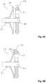
- the Fig. 6 shows an embodiment of the brake stroke ring system (1.0) in non-actuated state ( Fig. 6A ) and in the actuated state with the brake stroke completed ( Fig. 6B ).
- the driver can actuate a locking means (2.3) to reversibly fix the brake stroke ring (3.0) to the steering wheel (2.1) .
- This advantageously enables the function of a parking brake in a very simple manner.
- the embodiments of the invention shown are each to be understood as examples and not as restrictive.
- the invention can also be implemented in a different way.
- the brake stroke ring (3.0) can also be arranged inside the steering wheel (2.2) . This advantageously results in the brake stroke ring (3.0) being very compact and also no longer being visible.
- Another advantage is that the driver does not have to reach as far with his fingers to operate the brake ring. This is particularly advantageous for drivers with smaller hands.
Landscapes
- Engineering & Computer Science (AREA)
- Mechanical Engineering (AREA)
- Transportation (AREA)
- Braking Arrangements (AREA)
Claims (18)
- Système (1.0) d'anneau de frein à lever destiné à transmettre une course de freinage exercée par un conducteur à un système de freinage d'un véhicule, le véhicule comprenant un châssis de véhicule (2.0) etle système d'anneau de frein à lever comprend un anneau de frein (3.0) à lever adapté pour être tiré vers un volant (2.1) par un conducteur du véhicule, l'anneau de frein (3.0) à lever étant agencé autour d'un axe de volant (2.2),l'anneau de frein (3.0) à lever étant relié ou apte à être relié à une structure (3.1) de guidage d'anneau de frein à lever, la structure (3.1) de guidage d'anneau de frein à lever étant agencée de manière à être apte à être déplacée axialement le long de l'axe de volant (2.2) et à être apte à tourner radialement autour de l'axe de volant (2.2), la structure (3.1) de guidage d'anneau de frein à lever étant reliée ou est apte à être reliée à un découpleur (4.0), le découpleur comprenant une première moitié (4.1) de découpleur qui est orientée de manière proximale par rapport au volant (2.1) et une deuxième moitié (4.2) de découpleur qui est orientée de manière distale par rapport au volant (2.1), caractérisé en ce que le découpleur (4.0) est agencé de façon à ne pas transmettre une rotation radiale exercée sur la première moitié (4.1) de découpleur à la deuxième moitié (4.2) de découpleur, tandis qu'un déplacement axial est cependant transmis.
- Système d'anneau de frein à lever selon la revendication 1, dans lequel la structure (3.1) de guidage d'anneau de frein à lever est reliée à la première moitié (4.1) de découpleur.
- Système d'anneau de frein à lever selon la revendication 1 ou la revendication 2, dans lequel la structure (3.1) de guidage d'anneau de frein à lever présente une portion cylindrique creuse qui entoure l'axe de volant de manière à réaliser un guidage de la structure (3.1) de guidage d'anneau de frein à lever qui empêche un basculement de la structure de guidage d'anneau de frein à lever.
- Système d'anneau de frein à lever selon la revendication 3, dans lequel le diamètre intérieur de la portion cylindrique creuse représente au maximum 110 % du diamètre extérieur de l'axe de volant (2.2).
- Système d'anneau de frein à lever selon l'une des revendications 1 à 4, dans lequel la structure (3.1) de guidage d'anneau de frein à lever est reliée ou est apte à être reliée à la première moitié (4.1) de découpleur par complémentarité de forme axiale et par complémentarité de forme radiale, la première moitié (4.1) de découpleur étant agencée de manière à être apte à être déplacée axialement le long de l'axe de volant (2.2) et/ou à être apte à tourner radialement autour de l'axe de volant (2.2).
- Système d'anneau de frein à lever selon l'une des revendications 1 à 5, dans lequel la première moitié (4.1) de découpleur est reliée ou est apte à être reliée axialement par complémentarité de forme à la deuxième moitié (4.2) de découpleur.
- Système d'anneau de frein à lever selon l'une quelconque des revendications 1 à 6, dans lequel la deuxième moitié (4.2) de découpleur est apte à être déplacée axialement le long de l'axe de volant (2.2) et est agencée radialement de manière statique par rapport au châssis du véhicule (2.0), la première moitié (4.1) de découpleur étant positionnée de manière à être apte à tourner radialement contre la deuxième moitié (4.2) de découpleur.
- Système d'anneau de frein à lever selon la revendication 5 ou 7, dans lequel la deuxième moitié (4.2) de découpleur est reliée à au moins un moyen (5.0) de traction de frein, le moyen (5.0) de traction de frein étant conçu pour transmettre la course de freinage au système de freinage.
- Système d'anneau de frein à lever selon la revendication 7 ou la revendication 8, dans lequel la deuxième moitié de découpleur (4.2) est reliée à au moins un levier de frein (5.1), le levier de frein (5.1) étant relié au moyen (5.0) de traction de frein.
- Système d'anneau de frein à lever selon l'une des revendications 1 à 9, dans lequel le levier de frein (5.1) est en contact ponctuel avec une surface de contact périphérique (3.2) de la structure (3.1) de guidage d'anneau de frein à lever par une extrémité proximale (5.2) de levier de frein, l'extrémité proximale (5.2) de levier de frein étant agencée de façon à suivre le déplacement axial de la structure (3.1) de guidage d'anneau de frein à lever.
- Système d'anneau de frein à lever selon la revendication 10, dans lequel la surface de contact périphérique (3.2) de la structure (3.1) de guidage d'anneau de frein à lever présente une rainure (3.3) de guidage périphérique, la rainure (3.3) de guidage périphérique étant adaptée pour supporter de manière guidée l'extrémité proximale (5.2) de levier de frein.
- Système d'anneau de frein à lever selon l'une des revendications 1 à 11, dans lequel l'axe de volant (2.2) et/ou la surface de contact périphérique (3.2) de la structure (3.1) de guidage d'anneau de frein à lever et/ou la rainure (3.3) de guidage périphérique et/ou une face interne de la structure (3.4) de guidage d'anneau de frein à lever comprend au moins un élément formant palier (6.0) réducteur de friction.
- Système d'anneau de frein à lever selon la revendication 12, dans lequel l'élément formant palier (6.0) réducteur de friction est formé d'une matière plastique glissante (6.1).
- Système d'anneau de frein à lever selon la revendication 12 ou la revendication 13, dans lequel l'élément formant palier (6.0) réducteur de friction est adapté pour fournir une surface de contact ponctuelle entre la face interne de la structure (3.4) de guidage d'anneau de frein à lever et l'axe de volant (2.2).
- Système d'anneau de frein à lever selon la revendication 14, dans lequel l'élément formant palier (6.0) réducteur de friction est formé d'au moins trois roulements à billes (6.2) agencés de manière concentrique autour de l'axe de volant (2.2).
- Système d'anneau de frein à lever selon l'une quelconque des revendications 10 à 15, dans lequel l'extrémité proximale (5.2) de levier de frein comprend un roulement à billes (6.2) adapté pour fournir une surface de contact ponctuelle entre l'extrémité proximale (5.2) de levier de frein et la surface de contact (3.2) de la structure (3.1) de guidage d'anneau de frein à lever ou de la rainure de guidage (3.3).
- Système d'anneau de frein à lever selon l'une des revendications 1 à 16, dans lequel le système d'anneau de frein à lever comprend au moins un moyen d'encliquetage (2.3) qui est agencé de façon à fixer de manière réversible l'anneau de frein (3.0) à lever sur le volant (2.1) une fois le levage de frein effectué.
- Utilisation d'un système (1.0) d'anneau de frein à lever selon l'une des revendications 1 à 17 dans un véhicule pour la transmission d'une course de freinage exercée par un conducteur.
Applications Claiming Priority (1)
| Application Number | Priority Date | Filing Date | Title |
|---|---|---|---|
| LU102924 | 2022-04-01 |
Publications (3)
| Publication Number | Publication Date |
|---|---|
| EP4253210A1 EP4253210A1 (fr) | 2023-10-04 |
| EP4253210C0 EP4253210C0 (fr) | 2024-10-02 |
| EP4253210B1 true EP4253210B1 (fr) | 2024-10-02 |
Family
ID=82214420
Family Applications (1)
| Application Number | Title | Priority Date | Filing Date |
|---|---|---|---|
| EP23166342.8A Active EP4253210B1 (fr) | 2022-04-01 | 2023-04-03 | Système d'anneau de levage de frein |
Country Status (1)
| Country | Link |
|---|---|
| EP (1) | EP4253210B1 (fr) |
Family Cites Families (12)
| Publication number | Priority date | Publication date | Assignee | Title |
|---|---|---|---|---|
| US4653768A (en) | 1986-03-26 | 1987-03-31 | Keys Kenney L | Free spinning handlebar-brake cable connection |
| JPS62247989A (ja) | 1986-04-18 | 1987-10-29 | マエダ工業株式会社 | ハンドル部におけるブレ−キケ−ブルの配索構造 |
| US4770435A (en) | 1987-06-29 | 1988-09-13 | North America Tradimpex Cycles, Inc. | Freestyle bicycle construction |
| US5605076A (en) * | 1995-08-29 | 1997-02-25 | Wu; Chin-Chang | Swivel mechanism for a bicycle |
| WO1997027405A1 (fr) | 1996-01-26 | 1997-07-31 | Sram Corporation | Systeme d'actionnement de frein |
| US5992869A (en) | 1996-07-26 | 1999-11-30 | Yi-Chen; Chi | Anti-tangle mechanism for a bicycle |
| TW472743U (en) * | 2000-12-08 | 2002-01-11 | Chia Cherne Industry Co Ltd | Rotating seat for an acrobatic bicycle |
| US6422353B1 (en) * | 2001-02-26 | 2002-07-23 | Chang Hui Lin | Rotary coupling for brake assembly of cycles |
| DE102004053504B4 (de) * | 2003-11-27 | 2009-07-23 | GÖRING, Wolfgang | Rotorsystem, insbesondere für ein Zweirad oder Dreirad |
| JP2009173162A (ja) | 2008-01-24 | 2009-08-06 | Kawamura Cycle:Kk | 回転自在操舵輪を備えた自転車 |
| EP2590852B9 (fr) * | 2010-07-09 | 2018-11-28 | Savvy Design Holdings Limited | Jeu de direction de bicyclette avec dispositif de guidage de cables de transmission |
| DE202012101466U1 (de) * | 2012-04-20 | 2012-05-03 | Wolfgang Göring | Rotorsystem für ein Fahrrad, insbesondere Bowdenzugeinhängung für das Rotorsystem |
-
2023
- 2023-04-03 EP EP23166342.8A patent/EP4253210B1/fr active Active
Also Published As
| Publication number | Publication date |
|---|---|
| EP4253210A1 (fr) | 2023-10-04 |
| EP4253210C0 (fr) | 2024-10-02 |
Similar Documents
| Publication | Publication Date | Title |
|---|---|---|
| DE2235107C3 (de) | Ausgleichsgetriebe mit selbsttätiger Sperrung | |
| EP2266817B1 (fr) | Palier de roue pour axes de véhicules | |
| DE10110931C1 (de) | Bremsanlage und Kraftübertragungsanordnung hierfür | |
| DE102004004961B4 (de) | Fahrradnabe | |
| EP4253210B1 (fr) | Système d'anneau de levage de frein | |
| EP3986776B1 (fr) | Système de freinage pour véhicule, véhicule avec ledit système de freinage | |
| DE102014108422A1 (de) | Rad für eine Gehhilfe und Gehhilfe | |
| DE10130152B4 (de) | Trommelbremsenvorrichtung | |
| DE1555420A1 (de) | Mehrfachscheibenbremsen fuer radgetriebene Traktoren,insbesondere fuer landwirtschaftliche Zwecke | |
| DE3725692A1 (de) | Bremsvorrichtung | |
| DE20103667U1 (de) | Drehkupplung für ein Trickfahrrad | |
| DE102008063825A1 (de) | Lenk- und Bremsvorrichtung für Fahrzeuge | |
| EP4321353A1 (fr) | Système de stabilisation de remorque pour remorque de véhicule | |
| DE9407488U1 (de) | Fahrzeug mit Schubkurbelantrieb | |
| DE60002493T2 (de) | Vorrichtung zum fahren eines karts mit den händen für personen mit beinbehinderungen und damit ausgerüstetes kart | |
| DE10259448A1 (de) | Lenkrolle | |
| EP2791541B1 (fr) | Système de freinage pour véhicules utilitaires | |
| EP4245619A1 (fr) | Système de stabilisation pour une remorque de véhicule et procédé de stabilisation | |
| DE102018201599B4 (de) | Lenkvorrichtung für ein Fahrzeug und Fahrzeug | |
| DE4211338A1 (de) | Rollstuhl | |
| EP4480765B1 (fr) | Système de freinage | |
| DE300925C (fr) | ||
| DE3709418A1 (de) | Handbremse fuer kraftfahrzeuge | |
| DE9419360U1 (de) | Rücktrittbremse für Fahrräder mit Kettenschaltung | |
| EP1495958A2 (fr) | Moyeu à changement de vitèsse intégré pour véhicule à pédale à mécanisme d'entrainement direct |
Legal Events
| Date | Code | Title | Description |
|---|---|---|---|
| PUAI | Public reference made under article 153(3) epc to a published international application that has entered the european phase |
Free format text: ORIGINAL CODE: 0009012 |
|
| STAA | Information on the status of an ep patent application or granted ep patent |
Free format text: STATUS: THE APPLICATION HAS BEEN PUBLISHED |
|
| AK | Designated contracting states |
Kind code of ref document: A1 Designated state(s): AL AT BE BG CH CY CZ DE DK EE ES FI FR GB GR HR HU IE IS IT LI LT LU LV MC ME MK MT NL NO PL PT RO RS SE SI SK SM TR |
|
| STAA | Information on the status of an ep patent application or granted ep patent |
Free format text: STATUS: REQUEST FOR EXAMINATION WAS MADE |
|
| GRAP | Despatch of communication of intention to grant a patent |
Free format text: ORIGINAL CODE: EPIDOSNIGR1 |
|
| STAA | Information on the status of an ep patent application or granted ep patent |
Free format text: STATUS: GRANT OF PATENT IS INTENDED |
|
| 17P | Request for examination filed |
Effective date: 20240325 |
|
| RBV | Designated contracting states (corrected) |
Designated state(s): AL AT BE BG CH CY CZ DE DK EE ES FI FR GB GR HR HU IE IS IT LI LT LU LV MC ME MK MT NL NO PL PT RO RS SE SI SK SM TR |
|
| INTG | Intention to grant announced |
Effective date: 20240424 |
|
| GRAS | Grant fee paid |
Free format text: ORIGINAL CODE: EPIDOSNIGR3 |
|
| GRAA | (expected) grant |
Free format text: ORIGINAL CODE: 0009210 |
|
| STAA | Information on the status of an ep patent application or granted ep patent |
Free format text: STATUS: THE PATENT HAS BEEN GRANTED |
|
| AK | Designated contracting states |
Kind code of ref document: B1 Designated state(s): AL AT BE BG CH CY CZ DE DK EE ES FI FR GB GR HR HU IE IS IT LI LT LU LV MC ME MK MT NL NO PL PT RO RS SE SI SK SM TR |
|
| REG | Reference to a national code |
Ref country code: GB Ref legal event code: FG4D Free format text: NOT ENGLISH |
|
| REG | Reference to a national code |
Ref country code: CH Ref legal event code: EP |
|
| REG | Reference to a national code |
Ref country code: DE Ref legal event code: R096 Ref document number: 502023000194 Country of ref document: DE |
|
| REG | Reference to a national code |
Ref country code: IE Ref legal event code: FG4D Free format text: LANGUAGE OF EP DOCUMENT: GERMAN |
|
| U01 | Request for unitary effect filed |
Effective date: 20241101 |
|
| U07 | Unitary effect registered |
Designated state(s): AT BE BG DE DK EE FI FR IT LT LU LV MT NL PT RO SE SI Effective date: 20241112 |
|
| PG25 | Lapsed in a contracting state [announced via postgrant information from national office to epo] |
Ref country code: HR Free format text: LAPSE BECAUSE OF FAILURE TO SUBMIT A TRANSLATION OF THE DESCRIPTION OR TO PAY THE FEE WITHIN THE PRESCRIBED TIME-LIMIT Effective date: 20241002 Ref country code: IS Free format text: LAPSE BECAUSE OF FAILURE TO SUBMIT A TRANSLATION OF THE DESCRIPTION OR TO PAY THE FEE WITHIN THE PRESCRIBED TIME-LIMIT Effective date: 20250202 |
|
| PG25 | Lapsed in a contracting state [announced via postgrant information from national office to epo] |
Ref country code: ES Free format text: LAPSE BECAUSE OF FAILURE TO SUBMIT A TRANSLATION OF THE DESCRIPTION OR TO PAY THE FEE WITHIN THE PRESCRIBED TIME-LIMIT Effective date: 20241002 |
|
| PG25 | Lapsed in a contracting state [announced via postgrant information from national office to epo] |
Ref country code: NO Free format text: LAPSE BECAUSE OF FAILURE TO SUBMIT A TRANSLATION OF THE DESCRIPTION OR TO PAY THE FEE WITHIN THE PRESCRIBED TIME-LIMIT Effective date: 20250102 |
|
| U20 | Renewal fee for the european patent with unitary effect paid |
Year of fee payment: 3 Effective date: 20250317 |
|
| PG25 | Lapsed in a contracting state [announced via postgrant information from national office to epo] |
Ref country code: GR Free format text: LAPSE BECAUSE OF FAILURE TO SUBMIT A TRANSLATION OF THE DESCRIPTION OR TO PAY THE FEE WITHIN THE PRESCRIBED TIME-LIMIT Effective date: 20250103 |
|
| PG25 | Lapsed in a contracting state [announced via postgrant information from national office to epo] |
Ref country code: CZ Free format text: LAPSE BECAUSE OF FAILURE TO SUBMIT A TRANSLATION OF THE DESCRIPTION OR TO PAY THE FEE WITHIN THE PRESCRIBED TIME-LIMIT Effective date: 20241002 Ref country code: PL Free format text: LAPSE BECAUSE OF FAILURE TO SUBMIT A TRANSLATION OF THE DESCRIPTION OR TO PAY THE FEE WITHIN THE PRESCRIBED TIME-LIMIT Effective date: 20241002 |
|
| PG25 | Lapsed in a contracting state [announced via postgrant information from national office to epo] |
Ref country code: RS Free format text: LAPSE BECAUSE OF FAILURE TO SUBMIT A TRANSLATION OF THE DESCRIPTION OR TO PAY THE FEE WITHIN THE PRESCRIBED TIME-LIMIT Effective date: 20250102 |
|
| PG25 | Lapsed in a contracting state [announced via postgrant information from national office to epo] |
Ref country code: SM Free format text: LAPSE BECAUSE OF FAILURE TO SUBMIT A TRANSLATION OF THE DESCRIPTION OR TO PAY THE FEE WITHIN THE PRESCRIBED TIME-LIMIT Effective date: 20241002 |
|
| PG25 | Lapsed in a contracting state [announced via postgrant information from national office to epo] |
Ref country code: SK Free format text: LAPSE BECAUSE OF FAILURE TO SUBMIT A TRANSLATION OF THE DESCRIPTION OR TO PAY THE FEE WITHIN THE PRESCRIBED TIME-LIMIT Effective date: 20241002 |
|
| PLBE | No opposition filed within time limit |
Free format text: ORIGINAL CODE: 0009261 |
|
| STAA | Information on the status of an ep patent application or granted ep patent |
Free format text: STATUS: NO OPPOSITION FILED WITHIN TIME LIMIT |
|
| 26N | No opposition filed |
Effective date: 20250703 |
|
| PG25 | Lapsed in a contracting state [announced via postgrant information from national office to epo] |
Ref country code: MC Free format text: LAPSE BECAUSE OF FAILURE TO SUBMIT A TRANSLATION OF THE DESCRIPTION OR TO PAY THE FEE WITHIN THE PRESCRIBED TIME-LIMIT Effective date: 20241002 |
|
| U20 | Renewal fee for the european patent with unitary effect paid |
Year of fee payment: 4 Effective date: 20260213 |
|
| PG25 | Lapsed in a contracting state [announced via postgrant information from national office to epo] |
Ref country code: IE Free format text: LAPSE BECAUSE OF NON-PAYMENT OF DUE FEES Effective date: 20250403 |