EP4253227B1 - Structure d'aile à libération rapide et véhicule aérien sans pilote l'utilisant - Google Patents
Structure d'aile à libération rapide et véhicule aérien sans pilote l'utilisant Download PDFInfo
- Publication number
- EP4253227B1 EP4253227B1 EP23164693.6A EP23164693A EP4253227B1 EP 4253227 B1 EP4253227 B1 EP 4253227B1 EP 23164693 A EP23164693 A EP 23164693A EP 4253227 B1 EP4253227 B1 EP 4253227B1
- Authority
- EP
- European Patent Office
- Prior art keywords
- slot
- lock
- lock plate
- quick
- bolt
- Prior art date
- Legal status (The legal status is an assumption and is not a legal conclusion. Google has not performed a legal analysis and makes no representation as to the accuracy of the status listed.)
- Active
Links
Images


Classifications
-
- B—PERFORMING OPERATIONS; TRANSPORTING
- B64—AIRCRAFT; AVIATION; COSMONAUTICS
- B64U—UNMANNED AERIAL VEHICLES [UAV]; EQUIPMENT THEREFOR
- B64U10/00—Type of UAV
- B64U10/25—Fixed-wing aircraft
-
- B—PERFORMING OPERATIONS; TRANSPORTING
- B64—AIRCRAFT; AVIATION; COSMONAUTICS
- B64C—AEROPLANES; HELICOPTERS
- B64C1/00—Fuselages; Constructional features common to fuselages, wings, stabilising surfaces or the like
- B64C1/26—Attaching the wing or tail units or stabilising surfaces
-
- B—PERFORMING OPERATIONS; TRANSPORTING
- B64—AIRCRAFT; AVIATION; COSMONAUTICS
- B64U—UNMANNED AERIAL VEHICLES [UAV]; EQUIPMENT THEREFOR
- B64U30/00—Means for producing lift; Empennages; Arrangements thereof
- B64U30/10—Wings
- B64U30/12—Variable or detachable wings, e.g. wings with adjustable sweep
- B64U30/14—Variable or detachable wings, e.g. wings with adjustable sweep detachable
-
- B—PERFORMING OPERATIONS; TRANSPORTING
- B64—AIRCRAFT; AVIATION; COSMONAUTICS
- B64C—AEROPLANES; HELICOPTERS
- B64C2211/00—Modular constructions of airplanes or helicopters
-
- F—MECHANICAL ENGINEERING; LIGHTING; HEATING; WEAPONS; BLASTING
- F16—ENGINEERING ELEMENTS AND UNITS; GENERAL MEASURES FOR PRODUCING AND MAINTAINING EFFECTIVE FUNCTIONING OF MACHINES OR INSTALLATIONS; THERMAL INSULATION IN GENERAL
- F16B—DEVICES FOR FASTENING OR SECURING CONSTRUCTIONAL ELEMENTS OR MACHINE PARTS TOGETHER, e.g. NAILS, BOLTS, CIRCLIPS, CLAMPS, CLIPS OR WEDGES; JOINTS OR JOINTING
- F16B21/00—Means for preventing relative axial movement of a pin, spigot, shaft or the like and a member surrounding it; Stud-and-socket releasable fastenings
- F16B21/10—Means for preventing relative axial movement of a pin, spigot, shaft or the like and a member surrounding it; Stud-and-socket releasable fastenings by separate parts
- F16B21/16—Means for preventing relative axial movement of a pin, spigot, shaft or the like and a member surrounding it; Stud-and-socket releasable fastenings by separate parts with grooves or notches in the pin or shaft
Definitions
- the invention relates to the technical field of unmanned aerial vehicles, in particular to a quick-release wing structure and an unmanned aerial vehicle.
- the composite wing UAV is used increasingly widely.
- the aircraft has the multi-rotor parachute protection function.
- the composite wing UAV usually has two long wings to ensure the aircraft's long-term and long-distance cruise, but the long wings increase the difficulty of aircraft transportation and reduce the flexibility and convenience of the aircraft.
- the locking structures of the existing detachable wings are mostly complex, and to ensure the connection strength, it's a little difficult to disassemble and assemble the UAV.
- CN 211 281 437 U relates to an aircraft, where a locking mechanism and a connecting piece are arranged inside the fuselage and the wing, respectively.
- the locking mechanism includes a fixed base, an elastic element, and a locking plate connected in sequence, as well as a pressing member.
- the locking plate and the fixed base are provided with a channel for the connecting piece to pass through.
- the pressing member is provided with a connecting hole in the size of the channel.
- the connecting piece includes a lock pin and a fixed rod, and the outer circumferential surface of an end of the lock pin is provided with a first annular groove, and the locking plate is locked in the first annular groove.
- CN 207 157 486 U relates to a device for rapidly disassembling a wing of a drone.
- CN 112 520 011 A relates to a quick-release and quick-lock structure.
- US 8 453 973 B2 relates to a plug mounting for a detachable fastening of an equipment part.
- This invention aims to provide a quick-release wing structure and a UAV.
- the operation is convenient and fast, and it is convenient for wing to be disassembled and replacement with high stability and reliability.
- the present invention provides a quick-release wing structure, having the features defined in claim 1. Further preferred embodiments are provided in the dependent claims.
- An unmanned aerial vehicle comprises the quick-release wing structure according to any one of the preceding solutions.
- the invention has the beneficial effects that:
- the invention provides a quick-release wing structure, comprising a lock cylinder assembly and a lock head.
- the lock head cannot move freely, and the locking slot cannot separate itself from the lock plate, that is, the lock head and the lock cylinder assembly are clamped, thus completing the installation of the wing.
- the lock head in the wing is inserted into the lock cylinder assembly in the fuselage and automatically locked without other operations, and the operation is convenient and fast.
- the locking plate and the clamping hole jointly limit the movement of the lock head, which has high stability, better locking effect and higher reliability.
- connection should be understood in a broad sense, unless otherwise specified and limited, for example, they can be fixed connections, detachable connections, or integrated; It can be mechanical connection or electrical connection; It can be directly connected, or indirectly connected through intermediate media, or it can be the internal connection of two components or the interaction between two components.
- connection can be fixed connections, detachable connections, or integrated; It can be mechanical connection or electrical connection; It can be directly connected, or indirectly connected through intermediate media, or it can be the internal connection of two components or the interaction between two components.
- specific meaning of the above terms in the invention can be understood in a specific case.
- the "up" or “down” of the first feature in the second feature can include the direct contact of the first and second features, or the contact of the first and second features through other features between them instead of direct contact.
- the first feature "above” the second feature including the first feature being directly above and diagonally above the second feature, or only indicates that the horizontal height of the first feature is higher than the second feature.
- the first feature being “below” of the second feature include the first feature directly below and diagonally below the second feature, or only indicate that the horizontal height of the first feature is less than the second feature.
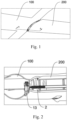
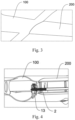
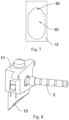
- the quick-release wing structure includes a lock cylinder assembly 1 and a lock head 2.
- the lock cylinder assembly 1 can be installed in the fuselage 100.
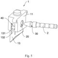
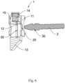
- the lock cylinder assembly 1 includes a shell 11 and a lock plate 12.
- the shell 11 is internally provided with an installation slot 10.
- the side wall of the installation slot 10 is provided with a clamping hole 20 connected with the installation slot 10, and the lock plate 12 is sliding in the installation slot 10.
- the lock head 2 is installed in the wing 200.
- the locking slot 30 is set on the periphery of the lock head 2.
- the lock head 2 can pass through the clamping hole 20 and drive the lock plate 12 to move.
- the lock head 2 When the locking slot 30 is facing the lock plate 12, the lock head 2 is clamped onto the locking slot 30 and fixed, and the lock head 2 is limited to the clamping hole 20.
- the lock plate 12 when the lock plate 12 is in the initial position, the lock plate 12 may partially cover the clamping hole 20, so that when the lock head 2 moves into the clamping hole 20, it can push the lock plate 12, and when the lock head 2 moves to the locking slot 30 directly facing the lock plate 12, the lock plate 12 can move towards the locking slot 30, so that the lock plate 12 can be able to clamp into the locking slot 30.
- the other side wall of the installation slot 10 can also be provided with a clamping hole 20. When the front end of the lock head 2 is longer, the lock head 2 can pass through the two clamping holes 20 in turn.
- the lock head 2 in the wing 200 is inserted into the lock cylinder assembly 1 in the fuselage 100 and then automatically locked, without other operations, which is convenient and fast.
- the lock plate 12 and the clamping hole 20 jointly limit the movement of the lock head 2, which has high stability, better locking effect and higher reliability.
- the front end of the lock head 2 is cone-shaped, which facilitates the front end of the lock head 2 to contact the lock plate 12 and push the lock plate 12 to move.
- the lock head 2 moves in the first direction.
- the lock plate 12 moves in the second direction along the conical front end, and the first direction is perpendicular to the second direction, thus improving the smoothness of disassembly and assembly of the wing 200 and the fuselage 100.
- the lock plate 12 and the lock head 2 are made of metal materials with high strength and high bearing capacity, thus improving the connection between the wing 200 and the fuselage 100.
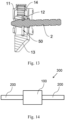
- the lock cylinder assembly 1 includes a bolt 13 and an elastic part 14.
- the bolt 13 slides along the groove depth direction of the installation slot 10 and is arranged in the installation slot 10.
- the inner wall of the bolt 13 is provided with a through hole for installation, the lock plate 12 is embedded in the through hole for installation, and the lock plate 12 is fixedly connected to the bolt 13.
- the two ends of the elastic part 14 are respectively connected to the bottom of the installation slot 10 and one end of the bolt 13. Under the action of the elastic part 14, the bolt 13 is pressed to the initial position.
- the lock head 2 When the lock head 2 extends into the clamping hole 20 and moves, the lock head 2 pushes the lock plate 12, drives the bolt 13 to move, and the bolt 13 compresses the elastic part 14.
- the lock head 2 moves to the locking slot 30 facing the lock plate 12, under the reset action of the elastic part 14, the bolt 13 faces the initial position, moving the lock plate 12 to clamp the locking slot 30.
- the lock plate 12 is driven to disengage from the locking slot 30, so that the lock head 2 can be pulled out from the clamping hole 20, and the removal of the wing 200 is completed, which is easy to operate. And because the lock plate 12 needs to be matched with the locking slot 30, so the lock plate 12 is thin.
- the lock plate 12 is embedded in the bolt 13 to improve the strength and pressure bearing capacity of the lock plate 12, ensuring the stability of the lock plate 12, and avoid the shaking of the lock plate 12 caused by stress, improving the lifespan and safety of the lock plate 12.
- the elastic part 14 is optional but not limited to compression spring, which is cheap and easy to obtain, and has good structural strength and elastic force.
- the end of the bolt 13 that is away from the elastic part 14 extends out of the installation slot 10 and protrudes from the fuselage 100, which is convenient to directly push the bolt 13, and the removal of the wing 200 can be realized without the help of tools.
- the end face of the bolt 13 away from the elastic part 14 is set as an inclined plane to match the shape of the fuselage 100 and improve the appearance beauty and smoothness of the fuselage 100.
- a limit slot 70 is clamped at the bottom of the installation slot 10, and one end of the elastic part 14 is embedded in the limit slot 70.
- the setting of the limit slot 70 avoids the bending of the elastic part 14 during the movement and ensures the normal operation of the elastic part 14, thus ensuring the normal operation of the bolt 13, and improving the reliability of the quick-release wing structure in the using process.
- the bottom of the installation slot 10 is provided with a through hole
- the cover of the through hole is provided with a limit cap
- the limit slot 70 is limited in the limit cap.
- the limit slot 70 is connected with the through hole and the installation slot 10.
- the setup of limit slot 70 can be achieved by the limit cap to avoid being limited by the thickness of the shell 11, otherwise it will be resulting in the smaller depth of the limit slot 70 or the reduced strength of the shell 11.
- the circumferential wall of the through-hole is provided with a clamping slot
- the lock plate 12 is clamped in the clamping slot
- the lock plate 12 is provided with a locking hole 50
- the part of the circumferential wall of the locking hole 50 is provided with an arc-shaped groove 60
- the arc-shaped groove 60 is matched with the bottom of the locking slot 30.
- part of the arc-shaped groove 60 is arranged on the lock plate 12, which protrudes from the clamping slot, and the rest of the lock plate 12 is located in the clamping slot, so that the bearing force by this part can be transferred to other parts of the lock plate 12 and to the bolt 13, further improving the stability of the quick-release wing structure.
- the opposite sides of the shell 11 are respectively provided with sliding holes 40
- the sliding holes 40 are connected with the installation slots 10
- the opposite sides of the bolt 13 are respectively provided with clips 131
- the two clips 131 are respectively connected to the two sliding holes 40 and can slide along the sliding holes 40.
- the clip 131 is clamped in the sliding hole 40 so that the bolt 13 can not only be installed in the shell 11, but also be moved.
- the elastic part 14 when the clip 131 abuts against one end of the sliding hole 40, the bolt 13 is in the initial position, that is, the initial position of the bolt 13 is determined by the fit of the clip 131 and the sliding hole 40.
- this embodiment also provides a UAV, which includes the above quick-release wing structure.
- a UAV which includes the above quick-release wing structure.
Landscapes
- Engineering & Computer Science (AREA)
- Mechanical Engineering (AREA)
- Aviation & Aerospace Engineering (AREA)
- Remote Sensing (AREA)
- Connection Of Plates (AREA)
- Clamps And Clips (AREA)
Claims (8)
- Structure d'aile à libération rapide, comprenant :un assemblage de cylindre de verrouillage (1) installé dans un corps (100), et l'assemblage de cylindre de verrouillage (1) comprend une coque (11) et une plaque de verrouillage (12) ;la coque (11) est dotée, à l'intérieur, d'une fente d'installation (10) ;une paroi latérale de la coque est dotée d'un trou de serrage (20) qui est connecté à la fente d'installation (10), et la plaque de verrouillage (12) est définie dans la fente d'installation (10) d'une manière coulissante ;une tête de verrouillage (2) installée dans une aile (200) ;la tête de verrouillage (2) est dotée d'une fente de verrouillage (30) sur une périphérie de la tête de verrouillage ;dans laquelle la tête de verrouillage (2) passe à travers le trou de serrage (20) pour entraîner la plaque de verrouillage (12) et l'amener à se déplacer ;dans laquelle la fente de verrouillage (30) fait face à la plaque de verrouillage (12), la tête de verrouillage (2) est serrée sur la fente de verrouillage (30) et fixée,l'assemblage de cylindre de verrouillage (1) comprenant en outre :un boulon (13) qui coulisse le long de la fente d'installation dans sa direction de profondeur, et qui est agencé dans la fente d'installation (10) ;la paroi intérieure du boulon (13) est dotée d'un trou traversant d'installation, la plaque de verrouillage (12) est enchâssée dans le trou traversant d'installation, et la plaque de verrouillage (12) est connectée de manière fixe au boulon (13) ;une partie élastique (14) ayant deux extrémités, dans laquelle les deux extrémités de la partie élastique (14) sont respectivement connectées à une extrémité de la plaque de verrouillage (12) et à une extrémité du boulon (13), dans laquelle une paroi circonférentielle du trou traversant d'installation est dotée d'une fente de serrage, la plaque de verrouillage (12) est serrée dans la fente de serrage, la plaque de verrouillage (12) est dotée d'un trou de verrouillage (50),caractérisé en ce queune partie de la paroi circonférentielle du trou de verrouillage (50) est dotée d'une rainure en forme d'arc (60), et la rainure en forme d'arc (60) est en correspondance avec un fond de la fente de verrouillage (30), et dans laquelleune partie de la rainure en forme d'arc (60) est agencée sur la plaque de verrouillage (12), qui se projette depuis la fente de serrage, et le reste de la plaque de verrouillage (12) est situé dans la fente de serrage.
- Structure d'aile à libération rapide selon la revendication 1, dans laquelle une fente limite (70) est définie au niveau d'un fond de la fente d'installation (10), et une extrémité de la partie élastique (14) est enchâssée dans la fente limite (70).
- Structure d'aile à libération rapide selon la revendication 1, dans laquelle la coque (11) a des trous de coulissement (40) prévus respectivement sur ses deux côtés opposés, les trous de coulissement (40) sont connectés à la fente d'installation (10), dans laquelle le boulon (13) a deux côtés opposés qui sont respectivement dotés d'agrafes (131), et lesdites agrafes (131) sont connectées respectivement aux deux trous de coulissement (40).
- Structure d'aile à libération rapide selon la revendication 3, dans laquelle la structure d'aile inclut en outre :
un fragment élastique (132), les deux côtés opposés du boulon (13) sont respectivement dotés d'une rainure anti-collision, une extrémité du fragment élastique (132) est connectée à un côté de la rainure anti-collision, et une autre extrémité est en projection vers l'extérieur et dotée des agrafes (131). - Structure d'aile à libération rapide selon la revendication 1, dans laquelle une extrémité du boulon (13) éloignée de la partie élastique (14) s'étend hors de la fente d'installation (10) et se projette depuis le corps (100).
- Structure d'aile à libération rapide selon la revendication 5, dans laquelle une face d'extrémité du boulon (13) éloignée de la partie élastique (14) est définie en tant que plan incliné.
- Structure d'aile à libération rapide selon la revendication 1, dans laquelle une extrémité avant de la tête de verrouillage (2) est de forme conique.
- Véhicule aérien sans équipage comprenant la structure d'aile à libération rapide décrite dans l'une quelconque des revendications 1 à 7.
Applications Claiming Priority (1)
| Application Number | Priority Date | Filing Date | Title |
|---|---|---|---|
| CN202220689659.2U CN217836006U (zh) | 2022-03-28 | 2022-03-28 | 一种机翼快拆结构及无人机 |
Publications (2)
| Publication Number | Publication Date |
|---|---|
| EP4253227A1 EP4253227A1 (fr) | 2023-10-04 |
| EP4253227B1 true EP4253227B1 (fr) | 2025-06-25 |
Family
ID=84018151
Family Applications (1)
| Application Number | Title | Priority Date | Filing Date |
|---|---|---|---|
| EP23164693.6A Active EP4253227B1 (fr) | 2022-03-28 | 2023-03-28 | Structure d'aile à libération rapide et véhicule aérien sans pilote l'utilisant |
Country Status (4)
| Country | Link |
|---|---|
| US (1) | US12103717B2 (fr) |
| EP (1) | EP4253227B1 (fr) |
| CN (1) | CN217836006U (fr) |
| ES (1) | ES3036696T3 (fr) |
Families Citing this family (3)
| Publication number | Priority date | Publication date | Assignee | Title |
|---|---|---|---|---|
| CN120308383A (zh) * | 2019-10-23 | 2025-07-15 | 深圳市道通智能航空技术股份有限公司 | 一种无人飞行器 |
| CN117401207A (zh) * | 2023-11-24 | 2024-01-16 | 南京航空航天大学 | 一种固定翼无人机起降辅助装置 |
| CN118405284B (zh) * | 2024-07-02 | 2024-09-13 | 西安羚控电子科技有限公司 | 一种机翼与机身的连接机构及无人机 |
Family Cites Families (7)
| Publication number | Priority date | Publication date | Assignee | Title |
|---|---|---|---|---|
| DE102007061926B4 (de) * | 2007-12-21 | 2011-12-08 | Sfs Intec Holding Ag | Steckhalterung |
| CN207157486U (zh) * | 2017-08-05 | 2018-03-30 | 北京海利天梦科技有限公司 | 无人机机翼快速拆装装置 |
| US11034447B2 (en) * | 2018-08-31 | 2021-06-15 | Insitu, Inc | Unmanned aerial vehicle (UAV) tethered wing recovery |
| CN211281437U (zh) * | 2019-09-30 | 2020-08-18 | 上海峰飞航空科技有限公司 | 飞行器 |
| CN110775248A (zh) * | 2019-10-21 | 2020-02-11 | 深圳市道通智能航空技术有限公司 | 一种无人机 |
| CN111204444B (zh) * | 2020-03-17 | 2025-04-22 | 中国科学院工程热物理研究所 | 组合式无人机的翼尖连接结构 |
| CN112520011A (zh) * | 2020-12-14 | 2021-03-19 | 中宇航通(北京)航空集团有限公司 | 一种快拆快锁结构、方法及无人机 |
-
2022
- 2022-03-28 CN CN202220689659.2U patent/CN217836006U/zh active Active
-
2023
- 2023-03-28 ES ES23164693T patent/ES3036696T3/es active Active
- 2023-03-28 EP EP23164693.6A patent/EP4253227B1/fr active Active
- 2023-03-28 US US18/191,861 patent/US12103717B2/en active Active
Also Published As
| Publication number | Publication date |
|---|---|
| US12103717B2 (en) | 2024-10-01 |
| US20230303273A1 (en) | 2023-09-28 |
| ES3036696T3 (en) | 2025-09-23 |
| EP4253227A1 (fr) | 2023-10-04 |
| CN217836006U (zh) | 2022-11-18 |
Similar Documents
| Publication | Publication Date | Title |
|---|---|---|
| EP4253227B1 (fr) | Structure d'aile à libération rapide et véhicule aérien sans pilote l'utilisant | |
| CN205602090U (zh) | 螺旋桨、电机、动力套装及无人飞行器 | |
| EP3476730B1 (fr) | Ensemble de connection moteur/helice | |
| WO2018107964A1 (fr) | Véhicule aérien sans pilote et ensemble d'alimentation, hélice et ensemble de base d'hélice de ce dernier | |
| EP4046906B1 (fr) | Véhicule aérien sans pilote | |
| CN209757504U (zh) | 螺旋桨快速拆装装置及无人机 | |
| CN112119010A (zh) | 快拆件、螺旋桨组件及多旋翼无人飞行器 | |
| KR101138501B1 (ko) | 소형 무인 항공기용 날개 연결 장치 | |
| CN108750139B (zh) | 一种机翼机身组装结构及具有其的飞行器 | |
| US20240166329A1 (en) | Unmanned aerial vehicle | |
| CN106672210A (zh) | 一种快拆桨及采用其的无人机 | |
| CN114604745A (zh) | 航行器用拔插式自动锁紧与释放起吊装置 | |
| CN211059153U (zh) | 按钮式弹簧锁 | |
| CN106585978B (zh) | 一种固定桨组件 | |
| CN108799293A (zh) | 一种带剪切环的抽芯铆钉 | |
| CN212099318U (zh) | 一种固锁组件和无人机 | |
| CN110896627A (zh) | 起落架结构及无人机 | |
| CN216834245U (zh) | 一种操作方便的机翼锁定机构 | |
| CN115626310B (zh) | 一种货运无人机翼身连接结构及连接方法 | |
| CN211592904U (zh) | 一种无人机 | |
| CN206520740U (zh) | 一种快拆桨及采用其的无人机 | |
| CN216997321U (zh) | 航行器用拔插式自动锁紧与释放起吊装置 | |
| CN212448050U (zh) | 快拆结构、起落架和无人机 | |
| EP0744555A1 (fr) | Plaque portant un écrou montée par adhésif | |
| CN219721896U (zh) | 一种航模飞机机翼快拆拆装机构 |
Legal Events
| Date | Code | Title | Description |
|---|---|---|---|
| PUAI | Public reference made under article 153(3) epc to a published international application that has entered the european phase |
Free format text: ORIGINAL CODE: 0009012 |
|
| STAA | Information on the status of an ep patent application or granted ep patent |
Free format text: STATUS: REQUEST FOR EXAMINATION WAS MADE |
|
| 17P | Request for examination filed |
Effective date: 20230329 |
|
| AK | Designated contracting states |
Kind code of ref document: A1 Designated state(s): AL AT BE BG CH CY CZ DE DK EE ES FI FR GB GR HR HU IE IS IT LI LT LU LV MC ME MK MT NL NO PL PT RO RS SE SI SK SM TR |
|
| GRAP | Despatch of communication of intention to grant a patent |
Free format text: ORIGINAL CODE: EPIDOSNIGR1 |
|
| STAA | Information on the status of an ep patent application or granted ep patent |
Free format text: STATUS: GRANT OF PATENT IS INTENDED |
|
| RIC1 | Information provided on ipc code assigned before grant |
Ipc: F16B 21/16 20060101ALN20250128BHEP Ipc: F16B 21/18 20060101ALI20250128BHEP Ipc: B64U 30/14 20230101ALI20250128BHEP Ipc: B64U 10/25 20230101ALI20250128BHEP Ipc: B64C 1/26 20060101AFI20250128BHEP |
|
| INTG | Intention to grant announced |
Effective date: 20250212 |
|
| GRAS | Grant fee paid |
Free format text: ORIGINAL CODE: EPIDOSNIGR3 |
|
| GRAA | (expected) grant |
Free format text: ORIGINAL CODE: 0009210 |
|
| STAA | Information on the status of an ep patent application or granted ep patent |
Free format text: STATUS: THE PATENT HAS BEEN GRANTED |
|
| AK | Designated contracting states |
Kind code of ref document: B1 Designated state(s): AL AT BE BG CH CY CZ DE DK EE ES FI FR GB GR HR HU IE IS IT LI LT LU LV MC ME MK MT NL NO PL PT RO RS SE SI SK SM TR |
|
| REG | Reference to a national code |
Ref country code: GB Ref legal event code: FG4D |
|
| REG | Reference to a national code |
Ref country code: CH Ref legal event code: EP |
|
| REG | Reference to a national code |
Ref country code: CH Ref legal event code: EP |
|
| REG | Reference to a national code |
Ref country code: IE Ref legal event code: FG4D |
|
| REG | Reference to a national code |
Ref country code: DE Ref legal event code: R096 Ref document number: 602023004196 Country of ref document: DE |
|
| REG | Reference to a national code |
Ref country code: ES Ref legal event code: FG2A Ref document number: 3036696 Country of ref document: ES Kind code of ref document: T3 Effective date: 20250923 |
|
| PG25 | Lapsed in a contracting state [announced via postgrant information from national office to epo] |
Ref country code: FI Free format text: LAPSE BECAUSE OF FAILURE TO SUBMIT A TRANSLATION OF THE DESCRIPTION OR TO PAY THE FEE WITHIN THE PRESCRIBED TIME-LIMIT Effective date: 20250625 |
|
| REG | Reference to a national code |
Ref country code: LT Ref legal event code: MG9D |
|
| PG25 | Lapsed in a contracting state [announced via postgrant information from national office to epo] |
Ref country code: NO Free format text: LAPSE BECAUSE OF FAILURE TO SUBMIT A TRANSLATION OF THE DESCRIPTION OR TO PAY THE FEE WITHIN THE PRESCRIBED TIME-LIMIT Effective date: 20250925 Ref country code: GR Free format text: LAPSE BECAUSE OF FAILURE TO SUBMIT A TRANSLATION OF THE DESCRIPTION OR TO PAY THE FEE WITHIN THE PRESCRIBED TIME-LIMIT Effective date: 20250926 |
|
| PG25 | Lapsed in a contracting state [announced via postgrant information from national office to epo] |
Ref country code: BG Free format text: LAPSE BECAUSE OF FAILURE TO SUBMIT A TRANSLATION OF THE DESCRIPTION OR TO PAY THE FEE WITHIN THE PRESCRIBED TIME-LIMIT Effective date: 20250625 |
|
| PG25 | Lapsed in a contracting state [announced via postgrant information from national office to epo] |
Ref country code: HR Free format text: LAPSE BECAUSE OF FAILURE TO SUBMIT A TRANSLATION OF THE DESCRIPTION OR TO PAY THE FEE WITHIN THE PRESCRIBED TIME-LIMIT Effective date: 20250625 |
|
| PG25 | Lapsed in a contracting state [announced via postgrant information from national office to epo] |
Ref country code: RS Free format text: LAPSE BECAUSE OF FAILURE TO SUBMIT A TRANSLATION OF THE DESCRIPTION OR TO PAY THE FEE WITHIN THE PRESCRIBED TIME-LIMIT Effective date: 20250925 |
|
| PG25 | Lapsed in a contracting state [announced via postgrant information from national office to epo] |
Ref country code: LV Free format text: LAPSE BECAUSE OF FAILURE TO SUBMIT A TRANSLATION OF THE DESCRIPTION OR TO PAY THE FEE WITHIN THE PRESCRIBED TIME-LIMIT Effective date: 20250625 |
|
| REG | Reference to a national code |
Ref country code: NL Ref legal event code: MP Effective date: 20250625 |
|
| PG25 | Lapsed in a contracting state [announced via postgrant information from national office to epo] |
Ref country code: NL Free format text: LAPSE BECAUSE OF FAILURE TO SUBMIT A TRANSLATION OF THE DESCRIPTION OR TO PAY THE FEE WITHIN THE PRESCRIBED TIME-LIMIT Effective date: 20250625 |
|
| PG25 | Lapsed in a contracting state [announced via postgrant information from national office to epo] |
Ref country code: PT Free format text: LAPSE BECAUSE OF FAILURE TO SUBMIT A TRANSLATION OF THE DESCRIPTION OR TO PAY THE FEE WITHIN THE PRESCRIBED TIME-LIMIT Effective date: 20251027 |
|
| REG | Reference to a national code |
Ref country code: AT Ref legal event code: MK05 Ref document number: 1806231 Country of ref document: AT Kind code of ref document: T Effective date: 20250625 |
|
| PG25 | Lapsed in a contracting state [announced via postgrant information from national office to epo] |
Ref country code: IS Free format text: LAPSE BECAUSE OF FAILURE TO SUBMIT A TRANSLATION OF THE DESCRIPTION OR TO PAY THE FEE WITHIN THE PRESCRIBED TIME-LIMIT Effective date: 20251025 |
|
| PG25 | Lapsed in a contracting state [announced via postgrant information from national office to epo] |
Ref country code: AT Free format text: LAPSE BECAUSE OF FAILURE TO SUBMIT A TRANSLATION OF THE DESCRIPTION OR TO PAY THE FEE WITHIN THE PRESCRIBED TIME-LIMIT Effective date: 20250625 Ref country code: SM Free format text: LAPSE BECAUSE OF FAILURE TO SUBMIT A TRANSLATION OF THE DESCRIPTION OR TO PAY THE FEE WITHIN THE PRESCRIBED TIME-LIMIT Effective date: 20250625 |
|
| PG25 | Lapsed in a contracting state [announced via postgrant information from national office to epo] |
Ref country code: CZ Free format text: LAPSE BECAUSE OF FAILURE TO SUBMIT A TRANSLATION OF THE DESCRIPTION OR TO PAY THE FEE WITHIN THE PRESCRIBED TIME-LIMIT Effective date: 20250625 |
|
| PG25 | Lapsed in a contracting state [announced via postgrant information from national office to epo] |
Ref country code: PL Free format text: LAPSE BECAUSE OF FAILURE TO SUBMIT A TRANSLATION OF THE DESCRIPTION OR TO PAY THE FEE WITHIN THE PRESCRIBED TIME-LIMIT Effective date: 20250625 |
|
| PG25 | Lapsed in a contracting state [announced via postgrant information from national office to epo] |
Ref country code: EE Free format text: LAPSE BECAUSE OF FAILURE TO SUBMIT A TRANSLATION OF THE DESCRIPTION OR TO PAY THE FEE WITHIN THE PRESCRIBED TIME-LIMIT Effective date: 20250625 |
|
| PG25 | Lapsed in a contracting state [announced via postgrant information from national office to epo] |
Ref country code: SK Free format text: LAPSE BECAUSE OF FAILURE TO SUBMIT A TRANSLATION OF THE DESCRIPTION OR TO PAY THE FEE WITHIN THE PRESCRIBED TIME-LIMIT Effective date: 20250625 |