EP4253237B1 - Table à plateaux formée d'un seul tenant avec charnières flexibles - Google Patents
Table à plateaux formée d'un seul tenant avec charnières flexibles Download PDFInfo
- Publication number
- EP4253237B1 EP4253237B1 EP23163115.1A EP23163115A EP4253237B1 EP 4253237 B1 EP4253237 B1 EP 4253237B1 EP 23163115 A EP23163115 A EP 23163115A EP 4253237 B1 EP4253237 B1 EP 4253237B1
- Authority
- EP
- European Patent Office
- Prior art keywords
- tray table
- flexural
- hinge
- table portion
- members
- Prior art date
- Legal status (The legal status is an assumption and is not a legal conclusion. Google has not performed a legal analysis and makes no representation as to the accuracy of the status listed.)
- Active
Links
Images



Classifications
-
- B—PERFORMING OPERATIONS; TRANSPORTING
- B64—AIRCRAFT; AVIATION; COSMONAUTICS
- B64D—EQUIPMENT FOR FITTING IN OR TO AIRCRAFT; FLIGHT SUITS; PARACHUTES; ARRANGEMENT OR MOUNTING OF POWER PLANTS OR PROPULSION TRANSMISSIONS IN AIRCRAFT
- B64D11/00—Passenger or crew accommodation; Flight-deck installations not otherwise provided for
- B64D11/06—Arrangements of seats, or adaptations or details specially adapted for aircraft seats
- B64D11/0638—Arrangements of seats, or adaptations or details specially adapted for aircraft seats with foldable tables, trays or cup holders
-
- B—PERFORMING OPERATIONS; TRANSPORTING
- B60—VEHICLES IN GENERAL
- B60N—SEATS SPECIALLY ADAPTED FOR VEHICLES; VEHICLE PASSENGER ACCOMMODATION NOT OTHERWISE PROVIDED FOR
- B60N3/00—Arrangements or adaptations of other passenger fittings, not otherwise provided for
- B60N3/001—Arrangements or adaptations of other passenger fittings, not otherwise provided for of tables or trays
- B60N3/002—Arrangements or adaptations of other passenger fittings, not otherwise provided for of tables or trays of trays
- B60N3/004—Arrangements or adaptations of other passenger fittings, not otherwise provided for of tables or trays of trays of foldable trays mounted on the back-rest
-
- E—FIXED CONSTRUCTIONS
- E05—LOCKS; KEYS; WINDOW OR DOOR FITTINGS; SAFES
- E05D—HINGES OR SUSPENSION DEVICES FOR DOORS, WINDOWS OR WINGS
- E05D1/00—Pinless hinges; Substitutes for hinges
- E05D1/02—Pinless hinges; Substitutes for hinges made of one piece
-
- E—FIXED CONSTRUCTIONS
- E05—LOCKS; KEYS; WINDOW OR DOOR FITTINGS; SAFES
- E05Y—INDEXING SCHEME ASSOCIATED WITH SUBCLASSES E05D AND E05F, RELATING TO CONSTRUCTION ELEMENTS, ELECTRIC CONTROL, POWER SUPPLY, POWER SIGNAL OR TRANSMISSION, USER INTERFACES, MOUNTING OR COUPLING, DETAILS, ACCESSORIES, AUXILIARY OPERATIONS NOT OTHERWISE PROVIDED FOR, APPLICATION THEREOF
- E05Y2900/00—Application of doors, windows, wings or fittings thereof
- E05Y2900/50—Application of doors, windows, wings or fittings thereof for vehicles
- E05Y2900/502—Application of doors, windows, wings or fittings thereof for vehicles for aircraft or spacecraft
Definitions
- Conventional aircraft tray table designs include multiple separate sub-assemblies.
- One example is a conventional tray table that splits into two sections, with a conventional hinge at the intersection of the two sections.
- An improved tray table that reduces components, materials, weight and cost, while also increasing the ease of installation, removal, rework, and customer experience is desirable.
- DE 10 2009 052593 relates to a vehicle seat with a table top.
- US 2020/039409 relates to tray table arms.
- DE 33 34 314 relates to a film hinge.
- a tray table for an aircraft is disclosed in accordance with claim 1.
- a method of 3D printing the tray table is also disclosed in accordance with claim 9.
- the method may be performed by stereolithography (SLA).
- SLA stereolithography
- inventive concepts are not limited in their application to the details of construction and the arrangement of the components or steps or methodologies set forth in the following description or illustrated in the drawings.
- inventive concepts disclosed herein may be practiced without these specific details.
- well-known features may not be described in detail to avoid unnecessarily complicating the present disclosure.
- inventive concepts disclosed herein are capable of other embodiments or of being practiced or carried out in various ways. Also, it is to be understood that the phraseology and terminology employed herein is for the purpose of description and should not be regarded as limiting.
- a letter following a reference numeral is intended to reference an embodiment of the feature or element that may be similar, but not necessarily identical, to a previously described element or feature bearing the same reference numeral (e.g., 1, 1a, 1b).
- Such shorthand notations are used for purposes of convenience only, and should not be construed to limit the inventive concepts disclosed herein in any way unless expressly stated to the contrary.
- "or" refers to an inclusive or and not to an exclusive or. For example, a condition A or B is satisfied by any one of the following: A is true (or present) and B is false (or not present), A is false (or not present) and B is true (or present), and both A and B are true (or present).
- any reference to “one embodiment” or “some embodiments” means that a particular element, feature, structure, or characteristic described in connection with the embodiment is included in at least one embodiment of the inventive concepts disclosed herein.
- the appearances of the phrase “in some embodiments” in various places in the specification are not necessarily all referring to the same embodiment, and embodiments of the inventive concepts disclosed may include one or more of the features expressly described or inherently present herein, or any combination or sub-combination of two or more such features, along with any other features which may not necessarily be expressly described or inherently present in the present disclosure.
- Embodiments of the present disclosure are directed to a tray table and a method of manufacturing the same.
- the tray table is a single-structured compliant mechanism employing flexural hinges.
- the flexural hinges are configured to provide motion (e.g., a pivot) between two adjacent portions/members by elastic deformation.
- the flexural hinges are folding points when deploying the tray table (when in use) or when stowing the tray table.
- the tray table is a single, unitary structure, and the components of the tray table may be manufactured using the same material.
- the present tray table and method provide several advantages. Deployment of the tray table may require less resultant force during stowage & deployment compared to a conventional tray table that comprises several separate parts. Since the present tray table has fewer parts than a conventional tray table, the present tray table may reduce weight (which may add up to significant weight savings on an aircraft when scaled across hundreds of passenger seats). The present tray table may be easier to manufacture using modern additive manufacturing (e.g., 3D printing). In particular, stereolithography (SLA) may enable the manufacture of precise and quality finished products in a short time.
- SLA stereolithography
- the combination of advantages described above reduces costs and may lead to other uses for compliant mechanisms (e.g., other uses that are not immediately intuitive).
- FIGS. 1-2 are perspective views respectively illustrating a tray table 200 for an aircraft in a stowed position and a deployed position, in accordance with one or more embodiments of the present disclosure.
- the tray table 200 comprises a base portion 210, a first surface portion 220, and a second surface portion 230.
- the tray table 200 is configured to be connected to an aircraft seat frame 100 via a hinge 205.
- the hinge 205 is configured to connect the base portion 210 to the aircraft seat frame 100.
- the hinge 205 is configured to pivot the base portion 210 with respect to the aircraft seat frame 100.
- the hinge 205 may include, for example, a bolt mechanism that rotates within a void or cavity and that is configured to secure or attach the base portion 210 to the frame 100.
- the base portion 210 may comprise a "U" shape with a straight section, and two curved sections connecting the straight section to the frame 100.
- the first surface portion 220 and second surface portion 230 are configured to be flat surfaces (e.g., for holding food, water, a book, etc.) when a user deploys the tray table 200.
- the first surface portion 220 and the second surface portion 230 are configured to fold in toward the aircraft seat frame 100 to stow the tray table 200, and to fold out away from the aircraft seat frame 100 to deploy the tray table 200.
- the first surface portion 220 and the second surface portion 230 may comprise a substantially rectangular cuboid shape having fillet edges or rounded or chamfered corners (although the portions 220, 230 are not limited thereto).
- the rectangular-cuboid shape may have a length at least 10 times longer than the thickness and a width at least 10 times longer than the thickness.
- FIG. 3 is a side view illustrating the tray table 200 in the stowed position, in accordance with one or more embodiments of the present disclosure.
- the tray table 200 includes flexural hinges 240 and 250. To begin deploying the tray table 100, a user may rotate the tray table 200 away from the frame 100.
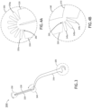
- FIGS. 4A-4B are side views respectively illustrating the flexural hinges 240, 250 showing the configuration of flexural members 245a-c, 255a-g in the stowed position of the tray table 200, in accordance with one or more embodiments of the present disclosure.
- the flexural members 245a-c, 255a-g have gaps in between each member 245a-c, 255a-g when the table 200 is in the stowed position.
- substantially circular material voids 260 may be formed proximal the attached ends of each flexural member 245a-c, 255a-g.
- each flexural member 245a-c, 255a-g may taper slightly toward its detached end.
- the flexural members 245a-c are pliable to enable the flexural hinge 240 to pivot, and the flexural members 255a-g are pliable to enable the second flexural hinge to pivot.
- Each of the flexural members 245a-c, 255a-g may have a substantially rectangular-cuboid shape (e.g., a bar shape). In some embodiments, the substantially rectangular-cuboid shape may have a length at least 10 times longer than the width, and a length at least 10 times longer than the thickness. Although three members 245a-c and seven members 255a-g are shown, it is contemplated that the members 245a-c, 255a-g may comprise any number of members.
- FIG. 5 is a side view illustrating the tray table 200 in the deployed position, in accordance with one or more embodiments of the present disclosure.
- a user may place items (i.e., food tray, laptop, phone, beverage, etc.) on the flat surface portions 220, 230 without the risk of spilling or dropping.
- FIGS. 6A-6B are side views respectively illustrating the flexural hinges 240, 250 showing the configuration of flexural members 245a-c, 255a-g in the deployed position of the tray table 200, in accordance with one or more embodiments of the present disclosure.
- the flexural members 245a-c, 255a-g are substantially adjacent to each other when the table 200 is in the deployed position, no (zero) gaps are between each member 245a-c, 255a-g, and the substantially circular voids 260 may deform slightly (e.g., elongate). In this way, the sidewalls of each member 245a-c, 255a-g may exert pressure on each other, which may provide stability (sturdiness) to the tray table 200.
- FIG. 7 is a flowchart illustrating a method of manufacturing a tray table for an aircraft, in accordance with one or more embodiments of the present disclosure.
- the method comprises 3D printing a tray table using stereolithography (SLA) or other additive manufacturing process.
- the tray table may be printed so that a base portion, a first surface portion, a first flexible hinge, a second surface portion, and a second flexible hinge are a single unitary structure.
- the tray table may comprise a single material, for example an engineering resin such as nylon polyamide (PA), however other materials are also contemplated herein.
- PA nylon polyamide
- the term “length” may be construed as the largest dimension of a given 3-dimensional structure or feature.
- the term “width” may be construed as the second largest dimension of a given 3-dimensional structure or feature.
- the term “thickness” may be construed as a smallest dimension of a given 3-dimensional structure or feature.
- a “major surface” may be construed as a surface defined by the two largest dimensions of a given structure or feature, which in the case of a structure or feature having a circular surface, may be defined by the radius of the circle.
Landscapes
- Engineering & Computer Science (AREA)
- Aviation & Aerospace Engineering (AREA)
- Transportation (AREA)
- Mechanical Engineering (AREA)
Claims (15)
- Table plateau (200) pour un aéronef, comprenant :une partie de base (210) pouvant être fixée à un cadre de siège d'aéronef par l'intermédiaire d'une charnière, la charnière étant opérationnelle pour faire pivoter la partie de base par rapport au cadre de siège d'aéronef ;une première partie de table plateau ;une première charnière de flexion (240) reliant la première partie de table plateau à la partie de base, la première charnière de flexion étant opérationnelle pour faire pivoter la première partie de table plateau par rapport à la partie de base ;une seconde partie de table plateau ; etune seconde charnière de flexion (250) reliant la seconde partie de table plateau à la première partie de table plateau, la seconde charnière de flexion étant opérationnelle pour faire pivoter la seconde partie de table plateau par rapport à la première partie de table plateau ;dans laquelle la première charnière de flexion (240) comprend des premiers éléments de flexion (245a-c) qui sont pliables pour permettre à la première charnière de flexion de pivoter ;dans laquelle la seconde charnière de flexion (250) comprend des seconds éléments de flexion (255a-c) qui sont pliables pour permettre à la seconde charnière de flexion de pivoter ; etdans laquelle la partie de base (210), la première partie de table plateau, la première charnière de flexion (240), la seconde partie de table plateau et la seconde charnière de flexion (250) sont formées d'un seul tenant ;caractérisée en ce que les premier et second éléments de flexion (245a-c ; 255a-c) sont formés de telle sorte que, lorsque les première et seconde parties de table plateau sont repliées pour ranger la table plateau, des espaces sont formés entre chaque élément de flexion, et, lorsque les première et seconde parties de table plateau sont dépliées pour déployer la table plateau, aucun espace n'est formé entre chaque élément de flexion.
- Table plateau selon la revendication 1, dans laquelle chacun des premiers éléments de flexion (245a-c) et chacun des seconds éléments de flexion (255a-c) ont une forme rectangulaire-cuboïde, et dans laquelle la forme rectangulaire-cuboïde a une longueur, une largeur et une épaisseur, et dans laquelle la longueur est au moins 10 fois plus longue que la largeur, et dans laquelle la longueur est au moins 10 fois plus longue que l'épaisseur.
- Table plateau selon la revendication 1 ou 2, dans laquelle chacune de la première partie de table plateau et de la seconde partie de table plateau ont une forme rectangulaire-cuboïde, et dans laquelle la forme rectangulaire-cuboïde a une longueur, une largeur et une épaisseur, dans laquelle la longueur est au moins 10 fois plus longue que l'épaisseur, dans laquelle la largeur est au moins 10 fois plus longue que l'épaisseur.
- Table plateau selon une quelconque revendication précédente, dans laquelle la table plateau (200) comprend du nylon polyamide (PA).
- Table plateau selon une quelconque revendication précédente, comprenant également des vides de matériau circulaires (260) formés à proximité d'extrémités attachées de chacun des premiers éléments de flexion (245a-c) et de chacun des seconds éléments de flexion (255a-c).
- Table plateau selon une quelconque revendication précédente, dans laquelle les extrémités détachées de chacun des premiers éléments de flexion (245a-c) et de chacun des seconds éléments de flexion (255a-c) comprennent des bords de congé.
- Table plateau selon une quelconque revendication précédente, dans laquelle la première partie de table plateau est configurée pour se replier contre la seconde partie de table plateau pour ranger la table plateau, et dans laquelle les première et seconde parties de table plateau sont coplanaires dans une condition déployée de la table plateau (200).
- Table plateau selon une quelconque revendication précédente, dans laquelle la seconde partie de table plateau pivote d'environ 180 degrés par rapport à la première partie de table plateau entre les conditions rangée et déployée de la table plateau, et la première partie de table plateau pivote d'environ 90 degrés par rapport à la partie de base (210) entre les conditions rangée et déployée de la table plateau (200).
- Procédé de fabrication d'une table plateau (200) pour un aéronef utilisant un processus de fabrication additive, la table plateau comprenant :une partie de base (210) pouvant être fixée à un cadre de siège d'aéronef par l'intermédiaire d'une charnière, la charnière étant opérationnelle pour faire pivoter la partie de base par rapport au cadre de siège d'aéronef ;une première partie de table plateau ;une première charnière de flexion (240) reliant la première partie de table plateau à la partie de base, la première charnière de flexion étant opérationnelle pour faire pivoter la première partie de table plateau par rapport à la partie de base ;une seconde partie de table plateau ; etune seconde charnière de flexion (250) reliant la seconde partie de table plateau à la première partie de table plateau, la seconde charnière de flexion étant opérationnelle pour faire pivoter la seconde partie de table plateau par rapport à la première partie de table plateau ;dans lequel la première charnière de flexion comprend des premiers éléments de flexion (245a-c) qui sont pliables pour permettre à la première charnière de flexion de pivoter ;dans lequel la seconde charnière de flexion comprend des seconds éléments de flexion (255a-c) qui sont pliables pour permettre à la seconde charnière de flexion de pivoter ; etdans lequel la partie de base, la première partie de table plateau, la première charnière de flexion, la seconde partie de table plateau et la seconde charnière de flexion sont formées d'un seul tenant ;dans lequel les premier et second éléments de flexion sont formés de telle sorte que, lorsque les première et seconde parties de table plateau sont repliées pour ranger la table plateau, des espaces sont formés entre chaque élément de flexion, et, lorsque les première et seconde parties de table plateau sont dépliées pour déployer la table plateau, aucun espace n'est formé entre chaque élément de flexion.
- Procédé selon la revendication 9, dans lequel le processus de fabrication additive comprend la stéréolithographie (SLA).
- Procédé selon la revendication 9 ou 10, dans lequel chacun des premiers éléments de flexion et chacun des seconds éléments de flexion ont une forme rectangulaire-cuboïde ayant des bords de congé, et dans lequel la forme sensiblement rectangulaire-cuboïde a une longueur, une largeur et une épaisseur, dans lequel la longueur est au moins 10 fois plus longue que la largeur, et dans lequel la longueur est au moins 10 fois plus longue que l'épaisseur.
- Procédé selon l'une quelconque des revendications 9 à 11, dans lequel chacune de la première partie de table plateau et de la seconde partie de table plateau ont une forme rectangulaire-cuboïde, et dans lequel la forme rectangulaire-cuboïde a une longueur, une largeur et une épaisseur, dans lequel la longueur est au moins 10 fois plus longue que l'épaisseur, dans lequel la largeur est au moins 10 fois plus longue que l'épaisseur.
- Procédé selon l'une quelconque des revendications 9 à 12, comprenant également des vides de matériau circulaires formés à proximité d'extrémités attachées de chacun des premiers éléments de flexion et de chacun des seconds éléments de flexion.
- Procédé selon l'une quelconque des revendications 9 à 13, dans lequel la première partie de table plateau est configurée pour se replier contre la seconde partie de table plateau pour ranger la table plateau, et dans lequel les première et seconde parties de table plateau sont coplanaires dans une condition déployée de la table plateau.
- Procédé selon l'une quelconque des revendications 9 à 14, dans lequel la seconde partie de table plateau pivote d'environ 180 degrés par rapport à la première partie de table plateau entre les conditions rangée et déployée de la table plateau, et la première partie de table plateau pivote d'environ 90 degrés par rapport à la partie de base entre les conditions rangée et déployée de la table plateau.
Applications Claiming Priority (2)
| Application Number | Priority Date | Filing Date | Title |
|---|---|---|---|
| IN202241019969 | 2022-04-01 | ||
| US18/104,922 US12351316B2 (en) | 2022-04-01 | 2023-02-02 | Integrally formed tray table with flexural hinges |
Publications (2)
| Publication Number | Publication Date |
|---|---|
| EP4253237A1 EP4253237A1 (fr) | 2023-10-04 |
| EP4253237B1 true EP4253237B1 (fr) | 2025-06-04 |
Family
ID=85724817
Family Applications (1)
| Application Number | Title | Priority Date | Filing Date |
|---|---|---|---|
| EP23163115.1A Active EP4253237B1 (fr) | 2022-04-01 | 2023-03-21 | Table à plateaux formée d'un seul tenant avec charnières flexibles |
Country Status (1)
| Country | Link |
|---|---|
| EP (1) | EP4253237B1 (fr) |
Families Citing this family (1)
| Publication number | Priority date | Publication date | Assignee | Title |
|---|---|---|---|---|
| FR3161401B1 (fr) * | 2024-04-17 | 2026-03-06 | Stellantis Auto Sas | Équipement bistable et monobloc. |
Family Cites Families (6)
| Publication number | Priority date | Publication date | Assignee | Title |
|---|---|---|---|---|
| DE3334314A1 (de) * | 1983-09-22 | 1985-04-11 | Helmuth 8336 Malgersdorf Bauer | Filmscharnier |
| US5876092A (en) * | 1997-12-05 | 1999-03-02 | Industrial Technology Research Institute | Foldaway table behind the backrest of a seat |
| DE102009052593A1 (de) * | 2009-11-10 | 2011-05-12 | GM Global Technology Operations LLC, Detroit | Fahrzeugsitz mit einer schwenkbaren Tischplatte |
| EP2827739B1 (fr) * | 2012-03-22 | 2018-08-08 | B/E Aerospace, Inc. | Table de genoux pliable de passager d'aéronef |
| DE102016113005A1 (de) * | 2016-07-14 | 2018-01-18 | Recaro Aircraft Seating Gmbh & Co. Kg | Flugzeugsitzvorrichtung |
| EP3601052A1 (fr) * | 2017-03-31 | 2020-02-05 | SABIC Global Technologies B.V. | Bras polymère pour table à plateaux et procédés de fabrication de celui-ci |
-
2023
- 2023-03-21 EP EP23163115.1A patent/EP4253237B1/fr active Active
Also Published As
| Publication number | Publication date |
|---|---|
| EP4253237A1 (fr) | 2023-10-04 |
Similar Documents
| Publication | Publication Date | Title |
|---|---|---|
| EP4253237B1 (fr) | Table à plateaux formée d'un seul tenant avec charnières flexibles | |
| US8336957B2 (en) | Tray table | |
| EP3552968B1 (fr) | Mécanisme pour obtenir une table de plateau extensible | |
| US10543921B2 (en) | Lightweight seat | |
| US20110210592A1 (en) | Vehicle seat | |
| WO2009126163A1 (fr) | Table-plateau pliable ajustable | |
| CN108116292B (zh) | 杯架 | |
| WO2018033599A1 (fr) | Arrangement de sièges, notamment d'un avion | |
| EP2661381A2 (fr) | Ensemble de table-plateau | |
| FR3076499A1 (fr) | Groupe de sièges pour un avion de ligne | |
| US20150375644A1 (en) | Integrated seat and backrest | |
| EP3446978B1 (fr) | Siège escamotable profilé | |
| EP4140828B1 (fr) | Modules d'airbag accouplés à l'accoudoir d'un siège de véhicule | |
| EP3619114B1 (fr) | Siège muni d'un système de verrouillage de tablette en cas de choc | |
| EP3105122B1 (fr) | Table à plateau facile à installer | |
| DE102011103620A1 (de) | Klapptischanordnung für einen Kraftwagen | |
| US20140319888A1 (en) | Folding seat assembly for a motor vehicle | |
| US12351316B2 (en) | Integrally formed tray table with flexural hinges | |
| EP4010248B1 (fr) | Dispositif de fermeture amovible motorise d'un espace, notamment a l'intérieur d'un avion | |
| US10843772B2 (en) | Collapsible watercraft with tandem and single-seat configurations | |
| FR2856903A1 (fr) | Systeme de rangement pour siege escamotable. | |
| EP4563472A1 (fr) | Rangée de sièges passagers de classe économique convertible en lit | |
| JP6167974B2 (ja) | 乗物用シートのテーブル | |
| EP3969359B1 (fr) | Embarcation pliable | |
| CN220314791U (zh) | 坐垫翻转装置、后排座椅及车辆 |
Legal Events
| Date | Code | Title | Description |
|---|---|---|---|
| PUAI | Public reference made under article 153(3) epc to a published international application that has entered the european phase |
Free format text: ORIGINAL CODE: 0009012 |
|
| STAA | Information on the status of an ep patent application or granted ep patent |
Free format text: STATUS: THE APPLICATION HAS BEEN PUBLISHED |
|
| AK | Designated contracting states |
Kind code of ref document: A1 Designated state(s): AL AT BE BG CH CY CZ DE DK EE ES FI FR GB GR HR HU IE IS IT LI LT LU LV MC ME MK MT NL NO PL PT RO RS SE SI SK SM TR |
|
| STAA | Information on the status of an ep patent application or granted ep patent |
Free format text: STATUS: REQUEST FOR EXAMINATION WAS MADE |
|
| 17P | Request for examination filed |
Effective date: 20240403 |
|
| RBV | Designated contracting states (corrected) |
Designated state(s): AL AT BE BG CH CY CZ DE DK EE ES FI FR GB GR HR HU IE IS IT LI LT LU LV MC ME MK MT NL NO PL PT RO RS SE SI SK SM TR |
|
| GRAP | Despatch of communication of intention to grant a patent |
Free format text: ORIGINAL CODE: EPIDOSNIGR1 |
|
| STAA | Information on the status of an ep patent application or granted ep patent |
Free format text: STATUS: GRANT OF PATENT IS INTENDED |
|
| INTG | Intention to grant announced |
Effective date: 20250128 |
|
| GRAS | Grant fee paid |
Free format text: ORIGINAL CODE: EPIDOSNIGR3 |
|
| GRAA | (expected) grant |
Free format text: ORIGINAL CODE: 0009210 |
|
| STAA | Information on the status of an ep patent application or granted ep patent |
Free format text: STATUS: THE PATENT HAS BEEN GRANTED |
|
| AK | Designated contracting states |
Kind code of ref document: B1 Designated state(s): AL AT BE BG CH CY CZ DE DK EE ES FI FR GB GR HR HU IE IS IT LI LT LU LV MC ME MK MT NL NO PL PT RO RS SE SI SK SM TR |
|
| REG | Reference to a national code |
Ref country code: GB Ref legal event code: FG4D |
|
| REG | Reference to a national code |
Ref country code: CH Ref legal event code: EP |
|
| REG | Reference to a national code |
Ref country code: DE Ref legal event code: R096 Ref document number: 602023003766 Country of ref document: DE |
|
| REG | Reference to a national code |
Ref country code: IE Ref legal event code: FG4D |
|
| REG | Reference to a national code |
Ref country code: NL Ref legal event code: MP Effective date: 20250604 |
|
| PG25 | Lapsed in a contracting state [announced via postgrant information from national office to epo] |
Ref country code: ES Free format text: LAPSE BECAUSE OF FAILURE TO SUBMIT A TRANSLATION OF THE DESCRIPTION OR TO PAY THE FEE WITHIN THE PRESCRIBED TIME-LIMIT Effective date: 20250604 Ref country code: FI Free format text: LAPSE BECAUSE OF FAILURE TO SUBMIT A TRANSLATION OF THE DESCRIPTION OR TO PAY THE FEE WITHIN THE PRESCRIBED TIME-LIMIT Effective date: 20250604 |
|
| REG | Reference to a national code |
Ref country code: LT Ref legal event code: MG9D |
|
| PG25 | Lapsed in a contracting state [announced via postgrant information from national office to epo] |
Ref country code: GR Free format text: LAPSE BECAUSE OF FAILURE TO SUBMIT A TRANSLATION OF THE DESCRIPTION OR TO PAY THE FEE WITHIN THE PRESCRIBED TIME-LIMIT Effective date: 20250905 Ref country code: NO Free format text: LAPSE BECAUSE OF FAILURE TO SUBMIT A TRANSLATION OF THE DESCRIPTION OR TO PAY THE FEE WITHIN THE PRESCRIBED TIME-LIMIT Effective date: 20250904 |
|
| PG25 | Lapsed in a contracting state [announced via postgrant information from national office to epo] |
Ref country code: PL Free format text: LAPSE BECAUSE OF FAILURE TO SUBMIT A TRANSLATION OF THE DESCRIPTION OR TO PAY THE FEE WITHIN THE PRESCRIBED TIME-LIMIT Effective date: 20250604 |
|
| PG25 | Lapsed in a contracting state [announced via postgrant information from national office to epo] |
Ref country code: BG Free format text: LAPSE BECAUSE OF FAILURE TO SUBMIT A TRANSLATION OF THE DESCRIPTION OR TO PAY THE FEE WITHIN THE PRESCRIBED TIME-LIMIT Effective date: 20250604 |
|
| PG25 | Lapsed in a contracting state [announced via postgrant information from national office to epo] |
Ref country code: HR Free format text: LAPSE BECAUSE OF FAILURE TO SUBMIT A TRANSLATION OF THE DESCRIPTION OR TO PAY THE FEE WITHIN THE PRESCRIBED TIME-LIMIT Effective date: 20250604 |
|
| PG25 | Lapsed in a contracting state [announced via postgrant information from national office to epo] |
Ref country code: RS Free format text: LAPSE BECAUSE OF FAILURE TO SUBMIT A TRANSLATION OF THE DESCRIPTION OR TO PAY THE FEE WITHIN THE PRESCRIBED TIME-LIMIT Effective date: 20250904 |
|
| PG25 | Lapsed in a contracting state [announced via postgrant information from national office to epo] |
Ref country code: LV Free format text: LAPSE BECAUSE OF FAILURE TO SUBMIT A TRANSLATION OF THE DESCRIPTION OR TO PAY THE FEE WITHIN THE PRESCRIBED TIME-LIMIT Effective date: 20250604 |
|
| PG25 | Lapsed in a contracting state [announced via postgrant information from national office to epo] |
Ref country code: NL Free format text: LAPSE BECAUSE OF FAILURE TO SUBMIT A TRANSLATION OF THE DESCRIPTION OR TO PAY THE FEE WITHIN THE PRESCRIBED TIME-LIMIT Effective date: 20250604 |
|
| PG25 | Lapsed in a contracting state [announced via postgrant information from national office to epo] |
Ref country code: PT Free format text: LAPSE BECAUSE OF FAILURE TO SUBMIT A TRANSLATION OF THE DESCRIPTION OR TO PAY THE FEE WITHIN THE PRESCRIBED TIME-LIMIT Effective date: 20251006 |
|
| REG | Reference to a national code |
Ref country code: AT Ref legal event code: MK05 Ref document number: 1800147 Country of ref document: AT Kind code of ref document: T Effective date: 20250604 |
|
| PG25 | Lapsed in a contracting state [announced via postgrant information from national office to epo] |
Ref country code: IS Free format text: LAPSE BECAUSE OF FAILURE TO SUBMIT A TRANSLATION OF THE DESCRIPTION OR TO PAY THE FEE WITHIN THE PRESCRIBED TIME-LIMIT Effective date: 20251004 |
|
| PG25 | Lapsed in a contracting state [announced via postgrant information from national office to epo] |
Ref country code: SM Free format text: LAPSE BECAUSE OF FAILURE TO SUBMIT A TRANSLATION OF THE DESCRIPTION OR TO PAY THE FEE WITHIN THE PRESCRIBED TIME-LIMIT Effective date: 20250604 Ref country code: AT Free format text: LAPSE BECAUSE OF FAILURE TO SUBMIT A TRANSLATION OF THE DESCRIPTION OR TO PAY THE FEE WITHIN THE PRESCRIBED TIME-LIMIT Effective date: 20250604 |
|
| PG25 | Lapsed in a contracting state [announced via postgrant information from national office to epo] |
Ref country code: CZ Free format text: LAPSE BECAUSE OF FAILURE TO SUBMIT A TRANSLATION OF THE DESCRIPTION OR TO PAY THE FEE WITHIN THE PRESCRIBED TIME-LIMIT Effective date: 20250604 |
|
| PG25 | Lapsed in a contracting state [announced via postgrant information from national office to epo] |
Ref country code: EE Free format text: LAPSE BECAUSE OF FAILURE TO SUBMIT A TRANSLATION OF THE DESCRIPTION OR TO PAY THE FEE WITHIN THE PRESCRIBED TIME-LIMIT Effective date: 20250604 |
|
| PG25 | Lapsed in a contracting state [announced via postgrant information from national office to epo] |
Ref country code: SK Free format text: LAPSE BECAUSE OF FAILURE TO SUBMIT A TRANSLATION OF THE DESCRIPTION OR TO PAY THE FEE WITHIN THE PRESCRIBED TIME-LIMIT Effective date: 20250604 |
|
| PG25 | Lapsed in a contracting state [announced via postgrant information from national office to epo] |
Ref country code: IT Free format text: LAPSE BECAUSE OF FAILURE TO SUBMIT A TRANSLATION OF THE DESCRIPTION OR TO PAY THE FEE WITHIN THE PRESCRIBED TIME-LIMIT Effective date: 20250604 |
|
| REG | Reference to a national code |
Ref country code: DE Ref legal event code: R097 Ref document number: 602023003766 Country of ref document: DE |
|
| PLBE | No opposition filed within time limit |
Free format text: ORIGINAL CODE: 0009261 |
|
| STAA | Information on the status of an ep patent application or granted ep patent |
Free format text: STATUS: NO OPPOSITION FILED WITHIN TIME LIMIT |
|
| PG25 | Lapsed in a contracting state [announced via postgrant information from national office to epo] |
Ref country code: DK Free format text: LAPSE BECAUSE OF FAILURE TO SUBMIT A TRANSLATION OF THE DESCRIPTION OR TO PAY THE FEE WITHIN THE PRESCRIBED TIME-LIMIT Effective date: 20250604 |
|
| PGFP | Annual fee paid to national office [announced via postgrant information from national office to epo] |
Ref country code: DE Payment date: 20260219 Year of fee payment: 4 |
|
| REG | Reference to a national code |
Ref country code: CH Ref legal event code: L10 Free format text: ST27 STATUS EVENT CODE: U-0-0-L10-L00 (AS PROVIDED BY THE NATIONAL OFFICE) Effective date: 20260416 |
|
| PGFP | Annual fee paid to national office [announced via postgrant information from national office to epo] |
Ref country code: FR Payment date: 20260220 Year of fee payment: 4 |