EP4253272B1 - Fermeture conique et système de fermeture - Google Patents
Fermeture conique et système de fermeture Download PDFInfo
- Publication number
- EP4253272B1 EP4253272B1 EP22179717.8A EP22179717A EP4253272B1 EP 4253272 B1 EP4253272 B1 EP 4253272B1 EP 22179717 A EP22179717 A EP 22179717A EP 4253272 B1 EP4253272 B1 EP 4253272B1
- Authority
- EP
- European Patent Office
- Prior art keywords
- closure
- skirt
- thread
- tamper
- container
- Prior art date
- Legal status (The legal status is an assumption and is not a legal conclusion. Google has not performed a legal analysis and makes no representation as to the accuracy of the status listed.)
- Active
Links
Images


Classifications
-
- B—PERFORMING OPERATIONS; TRANSPORTING
- B65—CONVEYING; PACKING; STORING; HANDLING THIN OR FILAMENTARY MATERIAL
- B65D—CONTAINERS FOR STORAGE OR TRANSPORT OF ARTICLES OR MATERIALS, e.g. BAGS, BARRELS, BOTTLES, BOXES, CANS, CARTONS, CRATES, DRUMS, JARS, TANKS, HOPPERS, FORWARDING CONTAINERS; ACCESSORIES, CLOSURES, OR FITTINGS THEREFOR; PACKAGING ELEMENTS; PACKAGES
- B65D41/00—Caps, e.g. crown caps or crown seals, i.e. members having parts arranged for engagement with the external periphery of a neck or wall defining a pouring opening or discharge aperture; Protective cap-like covers for closure members, e.g. decorative covers of metal foil or paper
- B65D41/32—Caps or cap-like covers with lines of weakness, tearing-strips, tags, or like opening or removal devices, e.g. to facilitate formation of pouring openings
- B65D41/34—Threaded or like caps or cap-like covers provided with tamper elements formed in, or attached to, the closure skirt
- B65D41/3423—Threaded or like caps or cap-like covers provided with tamper elements formed in, or attached to, the closure skirt with flexible tabs, or elements rotated from a non-engaging to an engaging position, formed on the tamper element or in the closure skirt
- B65D41/3428—Threaded or like caps or cap-like covers provided with tamper elements formed in, or attached to, the closure skirt with flexible tabs, or elements rotated from a non-engaging to an engaging position, formed on the tamper element or in the closure skirt the tamper element being integrally connected to the closure by means of bridges
-
- B—PERFORMING OPERATIONS; TRANSPORTING
- B65—CONVEYING; PACKING; STORING; HANDLING THIN OR FILAMENTARY MATERIAL
- B65D—CONTAINERS FOR STORAGE OR TRANSPORT OF ARTICLES OR MATERIALS, e.g. BAGS, BARRELS, BOTTLES, BOXES, CANS, CARTONS, CRATES, DRUMS, JARS, TANKS, HOPPERS, FORWARDING CONTAINERS; ACCESSORIES, CLOSURES, OR FITTINGS THEREFOR; PACKAGING ELEMENTS; PACKAGES
- B65D41/00—Caps, e.g. crown caps or crown seals, i.e. members having parts arranged for engagement with the external periphery of a neck or wall defining a pouring opening or discharge aperture; Protective cap-like covers for closure members, e.g. decorative covers of metal foil or paper
- B65D41/32—Caps or cap-like covers with lines of weakness, tearing-strips, tags, or like opening or removal devices, e.g. to facilitate formation of pouring openings
- B65D41/34—Threaded or like caps or cap-like covers provided with tamper elements formed in, or attached to, the closure skirt
- B65D41/3442—Threaded or like caps or cap-like covers provided with tamper elements formed in, or attached to, the closure skirt with rigid bead or projections formed on the tamper element and coacting with bead or projections on the container
- B65D41/3447—Threaded or like caps or cap-like covers provided with tamper elements formed in, or attached to, the closure skirt with rigid bead or projections formed on the tamper element and coacting with bead or projections on the container the tamper element being integrally connected to the closure by means of bridges
-
- B—PERFORMING OPERATIONS; TRANSPORTING
- B65—CONVEYING; PACKING; STORING; HANDLING THIN OR FILAMENTARY MATERIAL
- B65D—CONTAINERS FOR STORAGE OR TRANSPORT OF ARTICLES OR MATERIALS, e.g. BAGS, BARRELS, BOTTLES, BOXES, CANS, CARTONS, CRATES, DRUMS, JARS, TANKS, HOPPERS, FORWARDING CONTAINERS; ACCESSORIES, CLOSURES, OR FITTINGS THEREFOR; PACKAGING ELEMENTS; PACKAGES
- B65D41/00—Caps, e.g. crown caps or crown seals, i.e. members having parts arranged for engagement with the external periphery of a neck or wall defining a pouring opening or discharge aperture; Protective cap-like covers for closure members, e.g. decorative covers of metal foil or paper
- B65D41/32—Caps or cap-like covers with lines of weakness, tearing-strips, tags, or like opening or removal devices, e.g. to facilitate formation of pouring openings
- B65D41/325—Caps or cap-like covers with lines of weakness, tearing-strips, tags, or like opening or removal devices, e.g. to facilitate formation of pouring openings with integral internal sealing means
-
- B—PERFORMING OPERATIONS; TRANSPORTING
- B65—CONVEYING; PACKING; STORING; HANDLING THIN OR FILAMENTARY MATERIAL
- B65D—CONTAINERS FOR STORAGE OR TRANSPORT OF ARTICLES OR MATERIALS, e.g. BAGS, BARRELS, BOTTLES, BOXES, CANS, CARTONS, CRATES, DRUMS, JARS, TANKS, HOPPERS, FORWARDING CONTAINERS; ACCESSORIES, CLOSURES, OR FITTINGS THEREFOR; PACKAGING ELEMENTS; PACKAGES
- B65D55/00—Accessories for container closures not otherwise provided for
- B65D55/16—Devices preventing loss of removable closure members
-
- B—PERFORMING OPERATIONS; TRANSPORTING
- B65—CONVEYING; PACKING; STORING; HANDLING THIN OR FILAMENTARY MATERIAL
- B65D—CONTAINERS FOR STORAGE OR TRANSPORT OF ARTICLES OR MATERIALS, e.g. BAGS, BARRELS, BOTTLES, BOXES, CANS, CARTONS, CRATES, DRUMS, JARS, TANKS, HOPPERS, FORWARDING CONTAINERS; ACCESSORIES, CLOSURES, OR FITTINGS THEREFOR; PACKAGING ELEMENTS; PACKAGES
- B65D2251/00—Details relating to container closures
- B65D2251/10—Details of hinged closures
-
- B—PERFORMING OPERATIONS; TRANSPORTING
- B65—CONVEYING; PACKING; STORING; HANDLING THIN OR FILAMENTARY MATERIAL
- B65D—CONTAINERS FOR STORAGE OR TRANSPORT OF ARTICLES OR MATERIALS, e.g. BAGS, BARRELS, BOTTLES, BOXES, CANS, CARTONS, CRATES, DRUMS, JARS, TANKS, HOPPERS, FORWARDING CONTAINERS; ACCESSORIES, CLOSURES, OR FITTINGS THEREFOR; PACKAGING ELEMENTS; PACKAGES
- B65D2251/00—Details relating to container closures
- B65D2251/10—Details of hinged closures
- B65D2251/1008—Means for locking the closure in open position
-
- B—PERFORMING OPERATIONS; TRANSPORTING
- B65—CONVEYING; PACKING; STORING; HANDLING THIN OR FILAMENTARY MATERIAL
- B65D—CONTAINERS FOR STORAGE OR TRANSPORT OF ARTICLES OR MATERIALS, e.g. BAGS, BARRELS, BOTTLES, BOXES, CANS, CARTONS, CRATES, DRUMS, JARS, TANKS, HOPPERS, FORWARDING CONTAINERS; ACCESSORIES, CLOSURES, OR FITTINGS THEREFOR; PACKAGING ELEMENTS; PACKAGES
- B65D2251/00—Details relating to container closures
- B65D2251/20—Sealing means
-
- B—PERFORMING OPERATIONS; TRANSPORTING
- B65—CONVEYING; PACKING; STORING; HANDLING THIN OR FILAMENTARY MATERIAL
- B65D—CONTAINERS FOR STORAGE OR TRANSPORT OF ARTICLES OR MATERIALS, e.g. BAGS, BARRELS, BOTTLES, BOXES, CANS, CARTONS, CRATES, DRUMS, JARS, TANKS, HOPPERS, FORWARDING CONTAINERS; ACCESSORIES, CLOSURES, OR FITTINGS THEREFOR; PACKAGING ELEMENTS; PACKAGES
- B65D2401/00—Tamper-indicating means
- B65D2401/15—Tearable part of the closure
- B65D2401/30—Tamper-ring remaining connected to closure after initial removal
Definitions
- the field of the disclosure relates generally to a closure and a closure system, and more specifically to a closure that includes a tapered sidewall or skirt and a tapered internal thread, and a container that includes a tapered neck and a tapered external thread.
- Containers are often used to store products or contents. It is often desirable to close the container with a closure (e.g., a bottle cap) in order to contain the product or contents in the container.
- a closure e.g., a bottle cap
- Some known closures include a tamper-evident band that indicates whether the closure has been tampered with or removed from the container. Tamper-evident bands are desirable in certain applications (for example, in the food and beverage industry, pharmaceutical industry, etc.) in order to promote the safety of consumer products.
- Some known closures also include a tether that keeps the closure tethered or attached to the container when the closure is removed from the container. Tethered closure assemblies help to reduce the chance that the closure may be lost when it is removed from the container.
- the closure is placed on top of the container to cover an opening in the container, and is subsequently secured to the neck of the container.
- the closure is not immediately secured (e.g., threaded) to the container, and simply rests on top of the container.
- the container may be jostled (e.g., due to movement of the container along production or filling lines). If the closure is not firmly seated on the container neck, the closure may be disturbed and/or fall off the container, which can result in misapplied closures, closures being improperly presented to a capper of a capping/filling line, containers not being closed, etc.
- U.S. Patent Application Publication No. 2009/0283492 describes a tamper-evident cap that includes a closure member and an annular wall depending outward therefrom to a bottom rim.
- the present invention provides a closure for a container, as defined in claim 1.
- the present invention correspondingly provides a container closure system as defied in claim 11.
- Other optional features of the present invention are set forth in the dependent claims.
- a closure and a corresponding closure system are described herein that facilitate improved resistance of a closure that is placed over an opening of a container to being inadvertently removed from the container, for example, during container filling and/or capping operations, and during use by consumers.
- embodiments of the closures and closure systems disclosed herein utilize a taper effect to facilitate placement and/or securement of the closure on the neck of a container, e.g., during the manufacturing and assembly process.
- the closures and closure systems of the present disclosure can have a thread height that is substantially constant (i.e., is not reduced) along the height or length of the closure and/or the container neck.
- some known closures and closure systems have a reduced thread height near the bottom of the closure and/or near the top of the neck of the container, with the height of the thread increasing towards the top of the closure and/or the bottom of the neck.
- Embodiments of the closures and closure systems described herein can include container necks having external threads with a substantially constant or non-reduced height near the opening of the container and/or closures having internal threads with a substantially constant or non-reduced height.
- FIG. 1 is a side view of an example closure system 300 that includes a closure 100 and a container 200.
- FIG. 2 is a sectional view of the closure system 300 taken along line 2-2 in FIG. 1 .
- the closure 100 is connected to the container 200 at a neck 202 of the container 200.
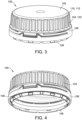
- FIG. 3 is a top perspective view of the closure 100
- FIG. 4 is a bottom perspective view of the closure 100
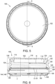
- FIG. 5 is a top view of the closure 100.
- the closure 100 includes a top panel 102, a sidewall or skirt 104 depending from the top panel 102, a tamper-evident band 106, and an attachment band 108.
- the closure 100 of the illustrated embodiment has a generally closed cylindrical shape, with the top panel 102 being generally circular and the skirt 104 being generally cylindrical. Additionally, the top panel 102 includes a transition section 110 along an outer peripheral edge 112 thereof that joins the skirt 104. In the illustrated embodiment, the transition section 110 is generally curved. In other embodiments, the transition section 110 can be of any suitable configuration that allows the closure 100 and/or the closure system 300 to function as described herein.
- FIG. 6 is a sectional view taken along line 6-6 in FIG. 5 .
- the example embodiment includes a sealing ring 114 that depends from the top panel 102 and extends circumferentially about a central axis 116 of the closure 100.
- the sealing ring 114 may be omitted, and the closure 100 may form a seal with the container 200 by other means, such as an induction heat seal.
- the central axis 116 coincides with line 2-2 in FIG. 1 , and also coincides with the central axis 119 of the container 200 when the closure 100 is installed on and secured to the container 200, as described further herein.
- the sealing ring 114 is spaced radially inward from the skirt 104, and is configured to sealingly engage a portion of the container 200 to which closure 100 is connected, for example, to inhibit contents from the container 200 from leaking or spilling out.
- the sealing ring 114 is spaced radially inward from the skirt 104 by a distance sufficient to receive a portion of the container 200 (e.g., neck 202) therebetween.
- the sealing ring 114 is shown as having a cross-sectional profile that includes a bottom edge 115 that is slanted towards the central axis 116.
- the slanted bottom edge 115 of the profile of the sealing ring 114 enables the sealing ring 114 to more effectively contact and seal an opening of the container (e.g., opening 232 shown in FIG. 9 ) to which closure 100 is connected.
- the sealing ring 114 may have any suitable configuration that allows the closure 100 and/or the closure system 300 to function as described herein.
- the skirt 104 depends from the top panel 102 and extends circumferentially about the central axis 116.
- the skirt 104 is spaced radially outward from the sealing ring 114.
- the skirt 104 extends from a first end 118 attached to the transition section 110 of the top panel 102 to a second end 120 opposite to the first end 118.
- the second end 120 may be, for example, at a location where the skirt 104 attaches to the tamper-evident band 106.
- the skirt 104 includes an exterior surface 122 and an interior surface 124 with at least one internal thread 126 extending radially inward from the interior surface 124.
- the at least one internal thread 126 can be a single, continuous internal thread extending helically around the interior surface 124 of the skirt 104, or the at least one thread 126 can include multiple different threads. As shown in FIG. 6 , for example, the at least one internal thread 126 includes three separate threads 126. Each of the separate threads 126 extends helically around the interior surface 124 of the skirt 104 from the second end 120 towards the first end 118. Moreover, in this embodiment, each thread 126 has a substantially constant height as the thread extends from the second end 120 towards the first end 118. For example, each thread 126 may have a constant height except for the thread start and end portions.
- FIG. 7 is an enlarged view of a portion of the closure 100 shown in FIG. 6 .
- the skirt 104 of the example closure 100 tapers radially outwards from the first end 118 to the second end 120 such that a diameter D of the skirt 104 (shown in FIG. 6 ) is greater at the second end 120 than at the first end 118.
- the skirt 104 can taper radially outward from the first end 118 to the second end 120 at any suitable angle that enables the closure 100 and/or the closure system 300 to function as described herein.
- an angle 130 of the taper shown with reference between the interior surface 124 of the skirt 104 and an axis 117 parallel to the central axis 116 in FIG.
- 7 can be between about 1° and about 10°, between about 1° and about 8°, between about 2° and about 10°, between about 1° and about 6°, between about 3° and about 8°, between about 5° and about 10°, between about 1° and about 4°, between about 3° and about 6°, between about 5° and about 8°, between about 7° and about 10°, between about 3° and about 5°, between about 4° and about 6°, or between about 5° and about 7°.
- the skirt 104 includes a radial taper of the diameter D (specifically, the diameter of the interior surface 124) of the skirt 104.
- the radial taper of the skirt 104 can be, for example and without limitation, a generally linear taper of the diameter D of the skirt 104, as is shown in the embodiment depicted in FIG. 6 .
- the radial taper of the diameter D of the skirt 104 can be of any suitable configuration (e.g., non-linear, non-constant, etc.) that enables closure 100 and/or closure system 300 to function as described herein.
- the diameter D of the skirt 104 at the second end 120 is between 1-10% greater than the diameter D of the skirt 104 at the first end 118, between 1-8% greater, between 2-8% greater, between 1-5% greater, between 2-6% greater, between 1-4% greater, between 2-5% greater, or between 2-4% greater. In one particular embodiment, the diameter D of the skirt 104 at the second end 120 is between 1-2 millimeters greater at the second end 120 of the skirt 104 than the diameter D at the first end 118 of the skirt 104.
- a radial spacing R between the central axis 116 and a peak or interior edge 132 of the internal threads 126 increases as the internal threads 126 extend toward the second end 120 of the skirt 104 due to the tapered skirt 104. That is, at locations of the internal threads 126 that are nearer to the first end 118 of the skirt 104, the radial spacing between the internal thread 126 and the central axis 116 may be smaller than the radial spacing between the internal thread 126 and the central axis 116 at locations that are nearer to the second end 120 of the skirt 104.
- the radial spacing R between the interior edge 132 of the threads 126 and the central axis 116 increases while the height of each thread remains the same or substantially the same. That is, the height of each thread 126 does not decrease (with the exception of the start portion of each thread 126 at the second end 120 as shown in FIG. 6 ) while the radial spacing R increases as the threads 126 extend towards the second end 120.
- the increase in the radial spacing R between the internal threads 126 and the central axis 116 may increase, for example, linearly, or any other suitable way that enables the closure 100 and/or closure system 300 to function as described herein.
- the tamper-evident band 106 is attached to the skirt 104 at the second end 120 of the skirt 104, and extends circumferentially about the central axis 116.
- the tamper-evident band 106 extends from a first end 134 attached to the skirt 104 (e.g., by one or more frangible tabs 154, described below) to an opposing second end 136.
- the attachment band 108 is hingedly connected to the second end 136 of the tamper-evident band 106, and extends radially inward therefrom.
- the attachment band 108 extends from a first end 144, attached to the second end 136 of the tamper-evident band 106 by a hinged attachment 148 (shown in FIG. 6 ), to a second, free end 146.
- the attachment band 108 is illustrated in an unfolded configuration in FIGs. 3, 4 , 6 , and 8 , although the attachment band 108 can be positioned in a folded configuration (shown in FIGs. 2 , 9, and 10 ), for example, prior to the closure 100 being attached to the container 200.
- the attachment band 108 can be folded radially inward about the hinged attachment 148 from the unfolded configuration to the folded configuration prior to attaching the closure 100 to the container 200.
- the attachment band 108 inhibits or prevents the tamper-evident band 106 from being removed from the container 200 when the closure 100 is removed (e.g., unthreaded) from the container 200.
- the tapered closure 100 can result in the tamper-evident band 106 having a diameter D1 that is larger than the diameter D of the skirt 104, for example, at any location along the skirt 104.
- the radial taper of the skirt 104 can continue into the diameter D1 of the tamper-evident band 106.
- the diameter D1 at the second end 136 of the tamper-evident band 106 is larger than the diameter D1 of the tamper-evident band 106 at the first end 134.
- the tamper-evident band 106 can be continuously tapered from the first end 134 to the second end 136, or the tamper-evident band 106 can be partially tapered (e.g., tapered along a portion or portions of the tamper-evident band 106). That is, the diameter D1 of the tamper-evident band 106 can be tapered in any suitable manner or remain constant at any portion of the tamper evident-band 106 that enables the closure 100 and the closure system 300 to function as described herein. In other embodiments not according to the invention, the tamper-evident band 106 is not tapered and has a substantially constant diameter D1 from the first end 134 to the second end 136.
- the tapered configuration of the closure (e.g., the increased diameter D of the skirt 104 and increased radial spacing of the internal threads 126 at the second end 120 of the skirt 104) can result in a relatively larger diameter D2 of the attachment band 108 in the folded configuration (shown in FIG. 9 ) as compared to prior closure designs.
- a tamper-evident band 106 that is also tapered can further increase the diameter D2 of the attachment band 108 in the folded configuration.
- the increased diameter D2 of the attachment band 108 in the folded configuration can facilitate retaining the closure 100 on the container 200 when the closure 100 is placed on the container 200, but prior to when the closure 100 is further secured (e.g., threaded) to the container 200 (e.g., during a filling operation of container 200).
- the tamper-evident band 106 is frangibly attached to the skirt 104 by at least one frangible tab 154 (shown in FIG. 8 ).
- the at least one frangible tab 154 is broken such that tamper-evident band 106 is no longer connected to the skirt 104 by the at least one frangible tab 154. Breaking, either partially or entirely, of the at least one frangible tab 154 may provide an indication the that closure 100 has previously been opened or removed from container 200.
- the tamper-evident band 106 is connected to the skirt 104 by 9 frangible tabs 154, although other embodiments may include more or less than 9 frangible tabs.
- the tamper-evident band 106 may also include a hinge 156 formed in the tamper-evident band 106 (shown in FIG. 8 ).
- the tamper-evident band 106 is tethered to the skirt 104 by the hinge 156 such that the skirt 104 and the tamper-evident band 106 remain tethered or attached via the hinge 156, even after the frangible tabs 154 are broken.
- the hinge 156 can facilitate movement of the closure 100 between an open position and a closed position, while also keeping the closure 100 connected to the container 200.
- the tamper-evident band 106 can also include one or more circumferentially-extending slots 158 that facilitate hingedly moving the closure 100 about the hinge 156.
- the example embodiment includes a single continuous slot 158 that is generally defined by parallel edges of the tamper-evident band 106.
- the slot 158 is generally circumferentially symmetrical about a center point of the hinge 156.
- the slot 158 extends circumferentially about the tamper-evident band 106 a sufficient distance to enable hingedly moving the closure between a closed position (shown in FIGs. 1 and 2 ) and an opened position (not shown) about the hinge 156.
- the hinge 156 also includes a deflectable tab 160 including a tooth 162 that extends radially outward from the tab 160.
- the deflectable tab 160 (specifically, the tooth 162) may be operable to engage a retention section 164 of the tamper-evident band 106 (shown in FIG. 7 ) to retain the closure 100 in the opened position.
- the bottom of the deflectable tab 160 may be spaced from the retention section 164 of the tamper-evident band 106 by an opening or gap that is sized to permit the tooth 162 of the deflectable tab 160 to pass therethrough when the closure 100 is rotated from a closed position (shown in FIG. 7 ) to an opened position.
- the tooth 162 When the closure 100 is in the opened position, the tooth 162 is disposed between the neck 202 and the retention section 164 of the tamper-evident band 106, and engages the retention section 164 to hold the closure 100 in the opened position.
- the deflectable tab 160 and the retention section 164 may have any suitable configuration that enables the closure 100 and/or the closure system 300 to function as described herein.
- the container 200 includes a sidewall 203 defining a cavity 204.
- the container 200 further includes a neck 202 extending from the sidewall 203 and defining an opening 232 to the cavity 204.
- the neck 202 extends circumferentially about a central axis 119 of the container 200, and includes an interior surface (not labeled) and an exterior surface 212. Further, the neck 202 extends from a first end 206 defining the opening 232 in a top 208 of the container 200, to a second end 210 joined to the sidewall 203. Aspects of the present disclosure are particularly advantageous when used with lightweight containers or bottles.
- Such containers can have relatively thin sidewalls and necks, and be constructed of, for example and without limitation, lightweight high-density polyethylene (HDPE).
- HDPE high-density polyethylene
- the container 200 can be formed of materials other than lightweight materials and/or have a construction without thin sidewalls.
- the exterior surface 212 of the neck 202 can include at least one external thread 214 formed on the exterior surface 212.
- the at least one thread 214 can be a single, continuous external thread extending helically around the neck 202, or the at least one thread 214 can include multiple different threads.
- the neck 202 also includes a tamper-evident bead 218 that protrudes radially outward form the exterior surface 212 of the neck 202 and circumferentially about the central axis 119. As shown in FIG.
- the tamper-evident bead 218 includes a generally straight edge 220 facing the second end 210 of the neck 202 and a tapered or curved edge 222 facing the first end 206 of the neck 202.
- the tamper-evident bead 218 engages the attachment band 108 of closure 100 when the closure 100 is connected to the container 200.
- the attachment band 108 in the folded configuration
- the attachment band 108 traverses the tamper-evident bead 218, the attachment band 108 returns to an undeflected position and engages the straight edge 220 of the tamper-evident bead 218, which inhibits removal of the attachment band 108 from the container neck 202, even when the rest of the closure 100 is removed.
- the neck 202 of the container 200 can be radially tapered outward between the first end 206 and the second end 210 of the neck 202 such that an outer diameter D3 of the neck 202 (measured along the exterior surface 212) is smaller near the top, open end 206 of the neck 202 than at the second end 210 of the neck 202.
- the neck 202 can be tapered along its entire length or along a portion of its length.
- the neck is radially tapered along a threaded region of the neck 202 that includes the at least one thread, and also along an unthreaded region of the neck 202 located between the tamper-evident bead 218 and the second end 210 of the neck 202.
- the radial taper of the neck 202 may extend along any portion of the neck 202 that enables closure 100 and/or closure system 300 to function as described herein. In some embodiments, for example, only the threaded region of the neck 202 is tapered radially outward.
- each external thread 214 has a substantially constant height as the thread extends from the first end 206 towards the second end 210.
- each external thread 214 may have a constant height except for the thread start and end portions.
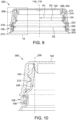
- FIG. 10 is an enlarged view of a portion of FIG. 9 .
- the neck 202 can taper radially outward at any suitable angle that enables the closure 100 and/or the closure system 300 to function as described herein.
- an angle 228 of the taper shown with reference between the exterior surface 212 of the neck 202 and an axis 230 parallel to the central axis 119 can be between about 1° and about 10°, between about 1° and about 8°, between about 2° and about 10°, between about 1° and about 6°, between about 3° and about 8°, between about 5° and about 10°, between about 1° and about 4°, between about 3° and about 6°, between about 5° and about 8°, between about 7° and about 10°, between about 3° and about 5°, between about 4° and about 6°, or between about 5° and about 7°.
- the neck 202 is tapered at the same angle as the skirt 104 of the closure 100.
- a radial spacing R1 between the external thread 214 of the neck 202 of the container 200 and the central axis 119 increases as the external thread 214 extends toward the second end 210 of the neck 202. That is, at locations of the external thread 214 that are nearer to the first end 206 of the neck 202, the radial spacing R1 between the external thread 214 and the central axis 119 is smaller than the radial spacing between the external thread 214 and the central axis 119 at locations that are nearer to the second end 210 the neck 202.
- the radial spacing R1 between the at least one external thread 214 of the neck 202 of the container 200 and the central axis 119 increases while the height of each external thread 214 remains the same or substantially the same. That is, the height of each external thread 214 does not decrease (with the exception of the start portion and end portion of each external thread 214) while the radial spacing R1 increases as each external thread 214 extends towards the second end 210.
- the closure 100 is positioned on top of the opening 232 of the container 200.
- the attachment band 108 may rest on the tamper-evident bead 218 (specifically, along the top curved edge 222).
- the closure 100 is subsequently secured to the container 200 by engaging the internal thread 126 of the skirt 104 of the closure 100 with the external thread 214 of the neck 202 of the container 200.
- the free end 146 of the attachment band 108 traverses the tamper-evident bead 218 and engages the straight edge 220 of the tamper-evident bead 218 of the neck 202 of the container 200, such that the tamper-evident band 106 is inhibited or prevented from being removed from container 200 with the rest of the closure 100.
- the attachment band 108 is folded into the folded configuration before the closure 100 is installed onto the container 200.
- An example of the attachment band 108 in the folded configuration and engaging the tamper-evident bead 218 of the neck 202 of the container 200 is shown in FIG. 9 .
- the tapered closure 100 and tapered neck 202 of the container 200 facilitate positioning and securing the closure 100 to the container 200 during certain processes, such as filling and/or capping procedures.
- the increased diameter D2 of the attachment band 108 in the folded configuration and the decreased diameter D3 of the first end 206 of the neck 202 and the corresponding external thread 214 of the neck 202 near the first end 206 of the neck 202 facilitate more securely placing and retaining the closure 100 on the neck 202 of the container 200 prior to the closure 100 being further secured (e.g., threaded) to the container 200.
- Such a configuration allows for less interference between portions of the closure 100 (e.g., the attachment band 108) and the neck 202 (e.g., external thread 214 of the neck 202 of the container 200), for example, during wipe on closure applications in container filling or capping operations.
- This configuration consequently allows the closure 100 to sit further down on the neck 202 of the container 200 (i.e., closer to the second end 210 of the neck 202 of the container 200) before the closure 100 is further secured to the container 200 via threading the closure 100 onto the container 200 via the internal thread 126 of the skirt 104 of the closure 100 engaging the external thread 214 of the neck 202 of the container 200.
- closure 100 sitting further down on the neck 202 of the container 200 before the closure 100 is further secured to the container it is more likely that the closure 100 will remain positioned on the neck 202 of the container 200 before the closure 100 is further secured to the container 200. Additionally, the closure 100 sitting further down on the neck 202 of the container 200 enables the closure 100 to be more-easily secured (e.g., threaded) to the container 200 via production equipment.
- the taper effect integrated into both the closure 100 and the container 200 helps to keep the closure 100 on the container 200 prior to the closure 100 being further secured to the container 200, and also enables the closure 100 to be better secured to the container 200 via production equipment.
- Such a configuration presents advantages during production (e.g., filling and capping operations) and consumer use.
- the tapered configuration of the closure 100 and neck 202 also facilitates opening and closing tethered closures (e.g., by the end user). For example, the increased clearance between the bottom of the closure and the top of the container neck resulting from the tapered configuration allow the tethered closure to be rotated between the closed and open position and vice-versa (e.g., via the hinge) without the closure and neck interfering or impeding movement of the closure.
- the tapered configuration of the closure 100 and neck 202 allows for a reduced clearance (i.e., tighter fit) between the closure and neck threads when the closure 100 is secured to the neck 202, thereby enhancing the engagement of the closure and neck threads.
- the increased engagement is particularly advantageous for lightweight containers or bottles (e.g., containers formed of thinwalled plastics, such as lightweight high-density polyethylene (HDPE) used to package fresh milk and juices), where deformation of the container neck might otherwise cause the closure to be dislodged from the container during transport and/or bottle handling.
- lightweight containers or bottles e.g., containers formed of thinwalled plastics, such as lightweight high-density polyethylene (HDPE) used to package fresh milk and juices
- the present disclosure provides at least the following technical benefits and advantages: (i) eliminating leaks and spills on container filling lines; (ii) eliminating leaks and spills during container distribution; (iii) eliminating leaks and spills during handling and use of the container by consumers; (iv) easy application of the closure to the container on container filling lines, (v) reduction in cost incurred to container filling corporations.
- the present disclosure provides solutions to at least the following problems: (i) a tendency of conventional closures placed on conventional containers to be inadvertently removed from the container prior to being secured to the container and (ii) application issues related to filling machines with wipe on closure applicators.
- closures are presented and applied to the containers via an inclined ramp down which the closures can slide, with the neck of the container being placed at the bottom of the ramp and receiving a closure via the ramp during application.
- the conventional closures may be incorrectly placed or aligned on the container on which they are applied in the wipe on application process due to, for example, interference between the internal side surfaces of the closure and the external side surfaces of the neck of the container.
- Incorrect placement or alignment of closures on the container can result in the closure being incorrectly presented to production equipment later on in the production process, which can cause the closure to be incorrectly (e.g., crookedly) installed on the container.
- the closure may not adequately seal the container, and/or the closure may not be adequately secured to the container.
- pressure within the container e.g., due to movement or jostling during transport
- the closure may cause the closure to be inadvertently removed from the container.
- the closure is not adequately sealed to the container, then the contents of the container may spill (e.g., during transportation or consumer use).
Landscapes
- Engineering & Computer Science (AREA)
- Mechanical Engineering (AREA)
- Closures For Containers (AREA)
Claims (15)
- Fermeture (100) pour récipient (200), ladite fermeture (100) comprenant :un panneau supérieur (102) ;une jupe (104) dépendant du panneau supérieur (102) et s'étendant circonférentiellement autour d'un axe central (116), la jupe (104) s'étendant depuis une première extrémité (118) fixée au panneau supérieur (102) jusqu'à une seconde extrémité (120) opposée à la première extrémité (118), la jupe (104) ayant une surface intérieure (124) et une surface extérieure (122) ;une bande inviolable (106) s'étendant depuis une première extrémité (134), fixée à la seconde extrémité (120) de la jupe (104), jusqu'à une seconde extrémité (136) ; etau moins un filetage (126) s'étendant depuis la surface intérieure (124) de la jupe (104);dans lequel la jupe (104) est effilée radialement vers l'extérieur depuis sa première extrémité (118) jusqu'à sa seconde extrémité (120) de telle sorte qu'un diamètre (D) de la jupe (104) au niveau de sa seconde extrémité (120) est supérieur au diamètre ( D) de la jupe (104) à sa première extrémité (118) ;dans lequel la bande inviolable (106) est effilée radialement vers l'extérieur sur au moins une partie depuis sa première extrémité (134) jusqu'à sa seconde extrémité (136) de telle sorte qu'un diamètre intérieur (D1) de la bande inviolable (106) soit à sa seconde extrémité (136) est supérieure au diamètre intérieur (D1) de la bande d'inviolabilité (106) à sa première extrémité (134),caractérisé en ce qu'une bande de fixation (108) est reliée de manière articulée à la seconde extrémité (136) de la bande d'inviolabilité (106).
- Fermeture (100) selon la revendication 1, dans laquelle le au moins un filetage (126) comprend une pluralité de filetages (126).
- Fermeture (100) selon la revendication 2, dans laquelle un espacement radial (R) entre l'axe central (116) et chaque filetage (126) augmente à mesure que chaque filetage (126) s'étend vers la deuxième extrémité (120) de la jupe (104) et une hauteur de filetage de chaque filetage (126) reste constante.
- Fermeture (100) selon la revendication 1, dans laquelle la bande d'inviolabilité (106) est attachée à la jupe (104) par une charnière (156) de telle sorte que la jupe (104) reste reliée à la bande d'inviolabilité (106) après l'ouverture de la fermeture (100).
- Fermeture (100) selon la revendication 4, dans laquelle une languette orientable (160) s'étend depuis la charnière (156), et dans laquelle au moins une dent (162) s'étend depuis la languette orientable (160) et peut être actionnée pour engager un une section de retenue (164) de la bande inviolable (106) pour maintenir la fermeture (100) dans une position ouverte.
- Fermeture (100) selon la revendication 1, dans laquelle un espacement radial (R) entre le au moins un filetage (126) et l'axe central (116) augmente à mesure que le au moins un filetage (126) s'étend vers la seconde extrémité (120) de la jupe (104).
- Fermeture (100) selon la revendication 1, dans laquelle un angle (130) entre la surface intérieure (124) de la jupe (104) et l'axe central (116) est compris entre 1° et 10°, éventuellement,
dans lequel la bande inviolable (106) est fixée de manière frangible à la jupe (104) par une pluralité de languettes frangibles (154). - Fermeture (100) selon la revendication 1, dans laquelle le panneau supérieur (102) comprend une section de transition (110) le long d'un bord périphérique externe (112) de celui-ci, dans laquelle la jupe (104) dépend du panneau supérieur (102) au niveau de la section de transition (110), la bande inviolable (106) étant fixée de manière frangible à la jupe (104) par une pluralité de languettes frangibles (154), la bande inviolable (106) étant attachée à la jupe (104) par une charnière (156) de telle sorte que la jupe (104) reste reliée à la bande inviolable (106) après la séparation des languettes frangibles (154), une languette orientable (160) s'étendant à partir de la charnière (156), et dans lequel au moins une dent (162) s'étend depuis la languette orientable (160) et peut être actionnée pour s'engager dans une section de retenue (164) de la bande inviolable (106) afin de maintenir la fermeture (100) dans une position ouverte, dans lequel le au moins un filetage (126) comprend une pluralité de filetages (126) s'étendant depuis la surface intérieure (124) de la jupe (104), et dans lequel la jupe (104) est effilée radialement vers l'extérieur à partir de la première extrémité (118) à la seconde extrémité (120) de telle sorte qu'un espacement radial (R) entre la pluralité de filetages (126) et l'axe central (116) augmente à mesure que chacun des filetages (126) s'étend vers la seconde extrémité (120) du jupe (104).
- Fermeture (100) selon la revendication 8, dans laquelle la jupe (104) est effilée radialement vers l'extérieur selon un angle compris dans une plage de 1° et 10° par rapport à l'axe central (116).
- Fermeture (100) selon la revendication 8, dans laquelle la bande d'inviolabilité (106) comprend au moins une fente (158) s'étendant circonférentiellement qui permet à la charnière (156) de se déplacer entre une position fermée et la position ouverte, et/ou,
dans lequel l'espacement radial (R) augmente à mesure que chaque filetage (126) s'étend vers la seconde extrémité (118) de la jupe (104) et une hauteur de filetage de chaque filetage (126) reste constante. - Système de fermeture (300) comprenant la fermeture (100) selon la revendication 1, le système de fermeture (300) comprenant en outre un récipient (200) comprenant :une paroi latérale (203) définissant une cavité (204) ; etun goulot (202) s'étendant depuis la paroi latérale (203) et définissant une ouverture (232) vers la cavité (204), le goulot (202) s'étendant depuis une première extrémité (206) définissant l'ouverture (232) jusqu'à une seconde extrémité (210) relié à la paroi latérale (203), le goulot (202) comprenant au moins un filetage (214) sur une surface extérieure (212) de celui-ci, le goulot (202) étant effilé radialement vers l'extérieur à partir de sa première extrémité (206) vers sa seconde extrémité (210) ;dans lequel le au moins un filetage (126) de la fermeture (100) est configuré pour s'engager par vissage avec au moins un filetage (214) du goulot du récipient (202) de telle sorte que la fermeture (100) puisse être reliée par vissage au récipient (200), et dans lequel un angle de conicité (130) de la jupe (104) correspond à un angle de conicité (228) du goulot (202).
- Système de fermeture (300) selon la revendication 11, dans lequel le au moins un filetage (214) du goulot (202) comprend une pluralité de filetages (214) et dans lequel le au moins un filetage (126) de la fermeture ( 100) comprend une pluralité de filetages (126).
- Système de fermeture (300) selon la revendication 11, dans lequel la bande d'inviolabilité (106) est attachée à la jupe (104) par une charnière (156) de telle sorte que la jupe (104) reste reliée à la jupe (104) la bande (106) après l'ouverture de la fermeture (100), facultativement,
dans lequel une languette orientable (160) s'étend depuis la charnière (156), et dans lequel au moins une dent (162) s'étend depuis la languette orientable (160) et peut être actionnée pour s'engager dans une section de retenue (164) de la bande inviolable ( 106) pour maintenir la fermeture (100) en position ouverte. - Système de fermeture (300) selon la revendication 11, dans lequel un espacement radial (R) entre le au moins un filetage (126) de la fermeture (100) et l'axe central (116) de la jupe (104) augmente au fur et à mesure le au moins un filetage (126) s'étend vers la deuxième extrémité (120) de la jupe (104), éventuellement,
l'espacement radial (R) augmentant à mesure que le ou les filetages (126) s'étendent vers la seconde extrémité (120) de la jupe (104) et une hauteur de filetage du ou des filetages (126) reste constante. - Système de fermeture (300) selon la revendication 11, dans lequel un angle (130) entre la surface intérieure (124) de la jupe (104) et l'axe central (116) de la jupe (104) est compris entre 1° et 10°, et/ou
dans lequel la bande inviolable (106) est fixée de manière frangible à la jupe (104) par une pluralité de languettes frangibles (154).
Priority Applications (1)
| Application Number | Priority Date | Filing Date | Title |
|---|---|---|---|
| EP24178404.0A EP4414284B1 (fr) | 2022-03-29 | 2022-06-17 | Fermeture conique et système de fermeture |
Applications Claiming Priority (1)
| Application Number | Priority Date | Filing Date | Title |
|---|---|---|---|
| US17/657,032 US11780652B1 (en) | 2022-03-29 | 2022-03-29 | Tapered closure and closure system |
Related Child Applications (2)
| Application Number | Title | Priority Date | Filing Date |
|---|---|---|---|
| EP24178404.0A Division-Into EP4414284B1 (fr) | 2022-03-29 | 2022-06-17 | Fermeture conique et système de fermeture |
| EP24178404.0A Division EP4414284B1 (fr) | 2022-03-29 | 2022-06-17 | Fermeture conique et système de fermeture |
Publications (3)
| Publication Number | Publication Date |
|---|---|
| EP4253272A1 EP4253272A1 (fr) | 2023-10-04 |
| EP4253272B1 true EP4253272B1 (fr) | 2024-08-07 |
| EP4253272C0 EP4253272C0 (fr) | 2024-08-07 |
Family
ID=82115942
Family Applications (2)
| Application Number | Title | Priority Date | Filing Date |
|---|---|---|---|
| EP24178404.0A Active EP4414284B1 (fr) | 2022-03-29 | 2022-06-17 | Fermeture conique et système de fermeture |
| EP22179717.8A Active EP4253272B1 (fr) | 2022-03-29 | 2022-06-17 | Fermeture conique et système de fermeture |
Family Applications Before (1)
| Application Number | Title | Priority Date | Filing Date |
|---|---|---|---|
| EP24178404.0A Active EP4414284B1 (fr) | 2022-03-29 | 2022-06-17 | Fermeture conique et système de fermeture |
Country Status (5)
| Country | Link |
|---|---|
| US (1) | US11780652B1 (fr) |
| EP (2) | EP4414284B1 (fr) |
| CA (1) | CA3192027A1 (fr) |
| ES (2) | ES2985761T3 (fr) |
| MX (1) | MX2023003653A (fr) |
Families Citing this family (2)
| Publication number | Priority date | Publication date | Assignee | Title |
|---|---|---|---|---|
| EP4206086A1 (fr) * | 2021-12-28 | 2023-07-05 | Tetra Laval Holdings & Finance S.A. | Capuchon de fermeture d'un emballage |
| NL2038578B1 (nl) * | 2024-09-04 | 2026-03-19 | Smartbottle B V | Container met afsluiteenheid |
Family Cites Families (20)
| Publication number | Priority date | Publication date | Assignee | Title |
|---|---|---|---|---|
| FR2421119A1 (fr) * | 1978-03-28 | 1979-10-26 | Captocap Ltd | Bouchon inviolable en matiere plastique |
| FR2499519A1 (fr) | 1981-02-11 | 1982-08-13 | Grussen Jean | Capsule de bouchage a vis avec anneau d'inviolabilite |
| US4798303A (en) * | 1987-04-15 | 1989-01-17 | Chesebrough-Pond's Inc. | Continuous thread closure assembly |
| IL110654A (en) * | 1993-08-19 | 1997-11-20 | Precision Valve Australia | Linerless closure for container |
| US5553727C1 (en) * | 1995-04-27 | 2001-09-04 | Rical Sa | Tamper-evident cap and neck finish |
| EP0879180B1 (fr) * | 1995-06-14 | 2003-02-26 | ZUMBUHL, Bruno | Bouchon filete pour des recipients a surpression interne |
| US5785195A (en) * | 1996-11-07 | 1998-07-28 | The Clorox Company | Conically threaded closure system |
| JP3241646B2 (ja) * | 1997-11-14 | 2001-12-25 | 日本クラウンコルク株式会社 | キャッピング性に優れたキャップ |
| JP2001114313A (ja) * | 1999-10-18 | 2001-04-24 | Shibazaki Seisakusho Ltd | 閉止装置 |
| JP2001146244A (ja) * | 1999-11-24 | 2001-05-29 | Kouno Jushi Kogyo Kk | 合成樹脂製キャップ |
| US7694835B1 (en) | 2005-01-04 | 2010-04-13 | Rexam Closures And Containers Inc. | Drafted neck finish having angled thread face and closure package |
| US20090283492A1 (en) | 2008-05-19 | 2009-11-19 | Omega Cap Solutions Llc | Visual Tamper-Evident Conical Screw Cap and Neck Finish |
| RU2478542C2 (ru) * | 2008-07-08 | 2013-04-10 | Джапан Краун Корк Ко., Лтд. | Выполненная из синтетической смолы крышка контейнера |
| US20120031871A1 (en) * | 2010-08-04 | 2012-02-09 | Omega Cap Soultions LLC | Step twist zipped visual tamper-evident cap and neck finish |
| US10836544B2 (en) | 2018-05-09 | 2020-11-17 | Silgan White Cap LLC | Closure with hinge |
| US10654625B2 (en) | 2018-10-12 | 2020-05-19 | Closure Systems International Inc. | Twist and flip lock closure |
| CN111924311B (zh) | 2019-05-13 | 2023-02-17 | 赫斯基注塑系统有限公司 | 用于容器的封闭装置 |
| IT201900013671A1 (it) | 2019-08-01 | 2021-02-01 | Sacmi | Tappo di chiusura per un contenitore. |
| US11505372B2 (en) | 2019-09-30 | 2022-11-22 | Berry Global, Inc. | Retainable closure |
| US11866231B2 (en) * | 2020-09-29 | 2024-01-09 | Novembal Usa Inc. | Hinged closure |
-
2022
- 2022-03-29 US US17/657,032 patent/US11780652B1/en active Active
- 2022-06-17 ES ES22179717T patent/ES2985761T3/es active Active
- 2022-06-17 ES ES24178404T patent/ES3038876T3/es active Active
- 2022-06-17 EP EP24178404.0A patent/EP4414284B1/fr active Active
- 2022-06-17 EP EP22179717.8A patent/EP4253272B1/fr active Active
-
2023
- 2023-03-06 CA CA3192027A patent/CA3192027A1/fr active Pending
- 2023-03-28 MX MX2023003653A patent/MX2023003653A/es unknown
Also Published As
| Publication number | Publication date |
|---|---|
| CA3192027A1 (fr) | 2023-09-29 |
| ES2985761T3 (es) | 2024-11-07 |
| ES3038876T3 (en) | 2025-10-15 |
| US20230312187A1 (en) | 2023-10-05 |
| EP4253272A1 (fr) | 2023-10-04 |
| EP4414284C0 (fr) | 2025-08-06 |
| US11780652B1 (en) | 2023-10-10 |
| EP4414284B1 (fr) | 2025-08-06 |
| EP4253272C0 (fr) | 2024-08-07 |
| EP4414284A1 (fr) | 2024-08-14 |
| MX2023003653A (es) | 2023-10-02 |
Similar Documents
| Publication | Publication Date | Title |
|---|---|---|
| EP0824466B1 (fr) | Bouchon et bague de goulot inviolables | |
| RU2387590C2 (ru) | Контейнер для напитков | |
| US5641099A (en) | Nestable pouring spout assembly | |
| RU2639099C2 (ru) | Крышка с установочной направляющей | |
| RU2478542C2 (ru) | Выполненная из синтетической смолы крышка контейнера | |
| US5513763A (en) | Cap for fluid container with threaded neck | |
| US9957076B2 (en) | Outsert for a metal container | |
| EP1114781B1 (fr) | Capsule inviolable pour une bouteille | |
| US11673719B2 (en) | Two-piece drop dispensing closure | |
| US20090283492A1 (en) | Visual Tamper-Evident Conical Screw Cap and Neck Finish | |
| CA2835861C (fr) | Fermeture | |
| EP4253272B1 (fr) | Fermeture conique et système de fermeture | |
| EP1440014B1 (fr) | Element de fermeture pour conteneurs | |
| CN111051208A (zh) | 封盖 | |
| US4726482A (en) | Tamper indicating package and molded plastic closure therefor | |
| US4111331A (en) | Tamper-proof closure device | |
| WO2020021094A1 (fr) | Système de fermeture de récipient de fluide | |
| US20110174761A1 (en) | Visual tamper-evident conical screw cap and neck finish | |
| CA1137029A (fr) | Recipient inviolable | |
| US20090139954A1 (en) | Closure With Improved Tamper-Evident Band | |
| JP2002542997A (ja) | プッシュプル式の再密閉可能なキャップを備えた密栓具 | |
| US20250346410A1 (en) | Container closure and dispensation system | |
| US20070158295A1 (en) | Tamper-evidencing container and closure structures | |
| WO2010096326A1 (fr) | Fermeture de distribution à charnières | |
| WO2001055000A1 (fr) | Bouchon filete inviolable et finition de col pour ce type de bouchon |
Legal Events
| Date | Code | Title | Description |
|---|---|---|---|
| PUAI | Public reference made under article 153(3) epc to a published international application that has entered the european phase |
Free format text: ORIGINAL CODE: 0009012 |
|
| STAA | Information on the status of an ep patent application or granted ep patent |
Free format text: STATUS: THE APPLICATION HAS BEEN PUBLISHED |
|
| AK | Designated contracting states |
Kind code of ref document: A1 Designated state(s): AL AT BE BG CH CY CZ DE DK EE ES FI FR GB GR HR HU IE IS IT LI LT LU LV MC MK MT NL NO PL PT RO RS SE SI SK SM TR |
|
| STAA | Information on the status of an ep patent application or granted ep patent |
Free format text: STATUS: REQUEST FOR EXAMINATION WAS MADE |
|
| 17P | Request for examination filed |
Effective date: 20231122 |
|
| RBV | Designated contracting states (corrected) |
Designated state(s): AL AT BE BG CH CY CZ DE DK EE ES FI FR GB GR HR HU IE IS IT LI LT LU LV MC MK MT NL NO PL PT RO RS SE SI SK SM TR |
|
| GRAP | Despatch of communication of intention to grant a patent |
Free format text: ORIGINAL CODE: EPIDOSNIGR1 |
|
| STAA | Information on the status of an ep patent application or granted ep patent |
Free format text: STATUS: GRANT OF PATENT IS INTENDED |
|
| INTG | Intention to grant announced |
Effective date: 20240213 |
|
| GRAS | Grant fee paid |
Free format text: ORIGINAL CODE: EPIDOSNIGR3 |
|
| GRAA | (expected) grant |
Free format text: ORIGINAL CODE: 0009210 |
|
| STAA | Information on the status of an ep patent application or granted ep patent |
Free format text: STATUS: THE PATENT HAS BEEN GRANTED |
|
| AK | Designated contracting states |
Kind code of ref document: B1 Designated state(s): AL AT BE BG CH CY CZ DE DK EE ES FI FR GB GR HR HU IE IS IT LI LT LU LV MC MK MT NL NO PL PT RO RS SE SI SK SM TR |
|
| REG | Reference to a national code |
Ref country code: GB Ref legal event code: FG4D |
|
| REG | Reference to a national code |
Ref country code: CH Ref legal event code: EP |
|
| REG | Reference to a national code |
Ref country code: DE Ref legal event code: R096 Ref document number: 602022005111 Country of ref document: DE |
|
| REG | Reference to a national code |
Ref country code: IE Ref legal event code: FG4D |
|
| U01 | Request for unitary effect filed |
Effective date: 20240807 |
|
| U07 | Unitary effect registered |
Designated state(s): AT BE BG DE DK EE FI FR IT LT LU LV MT NL PT RO SE SI Effective date: 20240902 |
|
| REG | Reference to a national code |
Ref country code: ES Ref legal event code: FG2A Ref document number: 2985761 Country of ref document: ES Kind code of ref document: T3 Effective date: 20241107 |
|
| PG25 | Lapsed in a contracting state [announced via postgrant information from national office to epo] |
Ref country code: NO Free format text: LAPSE BECAUSE OF FAILURE TO SUBMIT A TRANSLATION OF THE DESCRIPTION OR TO PAY THE FEE WITHIN THE PRESCRIBED TIME-LIMIT Effective date: 20241107 |
|
| PG25 | Lapsed in a contracting state [announced via postgrant information from national office to epo] |
Ref country code: PL Free format text: LAPSE BECAUSE OF FAILURE TO SUBMIT A TRANSLATION OF THE DESCRIPTION OR TO PAY THE FEE WITHIN THE PRESCRIBED TIME-LIMIT Effective date: 20240807 Ref country code: GR Free format text: LAPSE BECAUSE OF FAILURE TO SUBMIT A TRANSLATION OF THE DESCRIPTION OR TO PAY THE FEE WITHIN THE PRESCRIBED TIME-LIMIT Effective date: 20241108 |
|
| PG25 | Lapsed in a contracting state [announced via postgrant information from national office to epo] |
Ref country code: IS Free format text: LAPSE BECAUSE OF FAILURE TO SUBMIT A TRANSLATION OF THE DESCRIPTION OR TO PAY THE FEE WITHIN THE PRESCRIBED TIME-LIMIT Effective date: 20241207 |
|
| PG25 | Lapsed in a contracting state [announced via postgrant information from national office to epo] |
Ref country code: HR Free format text: LAPSE BECAUSE OF FAILURE TO SUBMIT A TRANSLATION OF THE DESCRIPTION OR TO PAY THE FEE WITHIN THE PRESCRIBED TIME-LIMIT Effective date: 20240807 |
|
| PG25 | Lapsed in a contracting state [announced via postgrant information from national office to epo] |
Ref country code: RS Free format text: LAPSE BECAUSE OF FAILURE TO SUBMIT A TRANSLATION OF THE DESCRIPTION OR TO PAY THE FEE WITHIN THE PRESCRIBED TIME-LIMIT Effective date: 20241107 |
|
| PG25 | Lapsed in a contracting state [announced via postgrant information from national office to epo] |
Ref country code: RS Free format text: LAPSE BECAUSE OF FAILURE TO SUBMIT A TRANSLATION OF THE DESCRIPTION OR TO PAY THE FEE WITHIN THE PRESCRIBED TIME-LIMIT Effective date: 20241107 Ref country code: PL Free format text: LAPSE BECAUSE OF FAILURE TO SUBMIT A TRANSLATION OF THE DESCRIPTION OR TO PAY THE FEE WITHIN THE PRESCRIBED TIME-LIMIT Effective date: 20240807 Ref country code: NO Free format text: LAPSE BECAUSE OF FAILURE TO SUBMIT A TRANSLATION OF THE DESCRIPTION OR TO PAY THE FEE WITHIN THE PRESCRIBED TIME-LIMIT Effective date: 20241107 Ref country code: IS Free format text: LAPSE BECAUSE OF FAILURE TO SUBMIT A TRANSLATION OF THE DESCRIPTION OR TO PAY THE FEE WITHIN THE PRESCRIBED TIME-LIMIT Effective date: 20241207 Ref country code: HR Free format text: LAPSE BECAUSE OF FAILURE TO SUBMIT A TRANSLATION OF THE DESCRIPTION OR TO PAY THE FEE WITHIN THE PRESCRIBED TIME-LIMIT Effective date: 20240807 Ref country code: GR Free format text: LAPSE BECAUSE OF FAILURE TO SUBMIT A TRANSLATION OF THE DESCRIPTION OR TO PAY THE FEE WITHIN THE PRESCRIBED TIME-LIMIT Effective date: 20241108 |
|
| PG25 | Lapsed in a contracting state [announced via postgrant information from national office to epo] |
Ref country code: SM Free format text: LAPSE BECAUSE OF FAILURE TO SUBMIT A TRANSLATION OF THE DESCRIPTION OR TO PAY THE FEE WITHIN THE PRESCRIBED TIME-LIMIT Effective date: 20240807 |
|
| PG25 | Lapsed in a contracting state [announced via postgrant information from national office to epo] |
Ref country code: CZ Free format text: LAPSE BECAUSE OF FAILURE TO SUBMIT A TRANSLATION OF THE DESCRIPTION OR TO PAY THE FEE WITHIN THE PRESCRIBED TIME-LIMIT Effective date: 20240807 |
|
| PG25 | Lapsed in a contracting state [announced via postgrant information from national office to epo] |
Ref country code: SK Free format text: LAPSE BECAUSE OF FAILURE TO SUBMIT A TRANSLATION OF THE DESCRIPTION OR TO PAY THE FEE WITHIN THE PRESCRIBED TIME-LIMIT Effective date: 20240807 |
|
| PLBE | No opposition filed within time limit |
Free format text: ORIGINAL CODE: 0009261 |
|
| STAA | Information on the status of an ep patent application or granted ep patent |
Free format text: STATUS: NO OPPOSITION FILED WITHIN TIME LIMIT |
|
| 26N | No opposition filed |
Effective date: 20250508 |
|
| PGFP | Annual fee paid to national office [announced via postgrant information from national office to epo] |
Ref country code: IE Payment date: 20250627 Year of fee payment: 4 |
|
| U20 | Renewal fee for the european patent with unitary effect paid |
Year of fee payment: 4 Effective date: 20250628 |
|
| PGFP | Annual fee paid to national office [announced via postgrant information from national office to epo] |
Ref country code: ES Payment date: 20250701 Year of fee payment: 4 |
|
| REG | Reference to a national code |
Ref country code: CH Ref legal event code: H13 Free format text: ST27 STATUS EVENT CODE: U-0-0-H10-H13 (AS PROVIDED BY THE NATIONAL OFFICE) Effective date: 20260127 |
|
| PG25 | Lapsed in a contracting state [announced via postgrant information from national office to epo] |
Ref country code: MC Free format text: LAPSE BECAUSE OF FAILURE TO SUBMIT A TRANSLATION OF THE DESCRIPTION OR TO PAY THE FEE WITHIN THE PRESCRIBED TIME-LIMIT Effective date: 20240807 |
|
| PG25 | Lapsed in a contracting state [announced via postgrant information from national office to epo] |
Ref country code: CH Free format text: LAPSE BECAUSE OF NON-PAYMENT OF DUE FEES Effective date: 20250630 |