EP4253295A1 - Procédé et dispositif de mise en communication d'ascenseur pour indiquer l'état de service d'un ascenseur - Google Patents
Procédé et dispositif de mise en communication d'ascenseur pour indiquer l'état de service d'un ascenseur Download PDFInfo
- Publication number
- EP4253295A1 EP4253295A1 EP22209475.7A EP22209475A EP4253295A1 EP 4253295 A1 EP4253295 A1 EP 4253295A1 EP 22209475 A EP22209475 A EP 22209475A EP 4253295 A1 EP4253295 A1 EP 4253295A1
- Authority
- EP
- European Patent Office
- Prior art keywords
- elevator
- call
- elevator car
- out device
- state
- Prior art date
- Legal status (The legal status is an assumption and is not a legal conclusion. Google has not performed a legal analysis and makes no representation as to the accuracy of the status listed.)
- Pending
Links
Images




Classifications
-
- B—PERFORMING OPERATIONS; TRANSPORTING
- B66—HOISTING; LIFTING; HAULING
- B66B—ELEVATORS; ESCALATORS OR MOVING WALKWAYS
- B66B1/00—Control systems of elevators in general
- B66B1/34—Details, e.g. call counting devices, data transmission from car to control system, devices giving information to the control system
- B66B1/46—Adaptations of switches or switchgear
- B66B1/468—Call registering systems
-
- B—PERFORMING OPERATIONS; TRANSPORTING
- B66—HOISTING; LIFTING; HAULING
- B66B—ELEVATORS; ESCALATORS OR MOVING WALKWAYS
- B66B1/00—Control systems of elevators in general
- B66B1/34—Details, e.g. call counting devices, data transmission from car to control system, devices giving information to the control system
- B66B1/46—Adaptations of switches or switchgear
-
- B—PERFORMING OPERATIONS; TRANSPORTING
- B66—HOISTING; LIFTING; HAULING
- B66B—ELEVATORS; ESCALATORS OR MOVING WALKWAYS
- B66B1/00—Control systems of elevators in general
- B66B1/34—Details, e.g. call counting devices, data transmission from car to control system, devices giving information to the control system
- B66B1/3415—Control system configuration and the data transmission or communication within the control system
- B66B1/3446—Data transmission or communication within the control system
- B66B1/3461—Data transmission or communication within the control system between the elevator control system and remote or mobile stations
-
- B—PERFORMING OPERATIONS; TRANSPORTING
- B66—HOISTING; LIFTING; HAULING
- B66B—ELEVATORS; ESCALATORS OR MOVING WALKWAYS
- B66B3/00—Applications of devices for indicating or signalling operating conditions of elevators
- B66B3/002—Indicators
-
- B—PERFORMING OPERATIONS; TRANSPORTING
- B66—HOISTING; LIFTING; HAULING
- B66B—ELEVATORS; ESCALATORS OR MOVING WALKWAYS
- B66B2201/00—Aspects of control systems of elevators
- B66B2201/10—Details with respect to the type of call input
- B66B2201/102—Up or down call input
-
- B—PERFORMING OPERATIONS; TRANSPORTING
- B66—HOISTING; LIFTING; HAULING
- B66B—ELEVATORS; ESCALATORS OR MOVING WALKWAYS
- B66B2201/00—Aspects of control systems of elevators
- B66B2201/40—Details of the change of control mode
- B66B2201/46—Switches or switchgear
- B66B2201/4607—Call registering systems
-
- B—PERFORMING OPERATIONS; TRANSPORTING
- B66—HOISTING; LIFTING; HAULING
- B66B—ELEVATORS; ESCALATORS OR MOVING WALKWAYS
- B66B2201/00—Aspects of control systems of elevators
- B66B2201/40—Details of the change of control mode
- B66B2201/46—Switches or switchgear
- B66B2201/4607—Call registering systems
- B66B2201/463—Wherein the call is registered through physical contact with the elevator system
Definitions
- the present application relates to elevator technology, in particular to a method for indicating a service status of an elevator, an elevator call-out device for implementing the method, and a computer-readable storage medium.
- a request to stop at a waiting floor can be sent to an elevator system by pressing an elevator call-out button installed near a landing door of an elevator.
- An elevator call-out panel usually contains two call-out buttons that request an elevator car to move up and down.
- Information received by an elevator controller from the call-out panel includes not only a floor to stop, but also a direction of movement of the elevator car required by a user after stopping at the floor.
- an elevator call-out device comprising:
- control unit is further configured to:
- the visual signs are one or more of the following items: call-out button indicator, arrival indicator, and upward and downward markers displayed on a display screen.
- control unit is configured to switch one of the visual signs from the normally lit state to the flashing state in the following manner:
- control unit is configured to switch one of the visual signs from the normally lit state to the flashing state in the following manner:
- control unit is further configured to switch one of the visual signs from the normally lit state to the flashing state in the following manner:
- control unit is further configured to switch one of the visual signs from the normally lit state to the flashing state in the following manner:
- control unit is configured to switch one of the visual signs from the flashing state to the off state in the following manner:
- control unit is configured to switch one of the visual signs from the off state to the normally lit state in the following manner: detecting whether the call-out button is pressed or whether an object hovers in its vicinity;
- one of the visual signs which corresponds to the direction of movement indicated by the call-out button, is caused to enter the normally lit state.
- the elevator call-out device is an integrated call-out panel assembly or a discrete call-out panel assembly.
- a frequency value within a normal range of respiratory frequency is determined as the luminous intensity or frequency of color change of the visual sign.
- an elevator system comprising:
- a method for indicating a service status of an elevator comprising:
- a computer-readable storage medium in which an instruction is stored.
- the processor is caused to execute the above method.
- first and second do not indicate the order of the units in terms of time, space, size, etc., but are merely used to distinguish the units.
- FIG. 1 is a schematic block diagram of a typical elevator call-out device.
- An elevator call-out device 100 shown in FIG. 1 includes a call-out button 101, a button indicator 102, and a control unit 103.
- the elevator call-out device 100 may take the form of an integrated call-out panel assembly as shown in FIG. 2A , for example.
- the call-out panel assembly 200A shown in FIG. 2A is usually installed on one side of a landing door of an elevator, and buttons 201, 202 corresponding to "upward” and “downward” directions and display screen 203 displaying information such as a current floor of an elevator car are arranged on a surface of a panel 204, and button indicators (not shown) are arranged behind the buttons 201 and 202.
- button indicators (not shown) are arranged behind the buttons 201 and 202.
- the display screen 203 is used to display information about the current floor of the elevator car, to display a direction in which the elevator car arrives at the current floor or the elevator car is moving or will move (shown in the figure with thick solid arrows for example).
- the elevator call-out device 100 may also take the form of a discrete call-out panel assembly as shown in FIG. 2B , for example.
- the call-out panel assembly 200B shown in FIG. 2B includes a first panel 205 and a second panel 206, which are installed, for example, on one side of the landing door of the elevator and above the landing door, respectively.
- Buttons 201, 202 corresponding to the "upward” and “downward” directions are arranged on the surface of the first panel 205, and button indicators (not shown) are arranged behind the buttons 201, 202.
- the display screen 203 is arranged on the surface of the second panel 206 to display information about the current floor of the elevator car, to display prompt information of a direction in which the elevator car arrives at the current floor or the elevator car is moving or will move (shown in the figure with thick solid arrows for example).
- the corresponding button indicator is illuminated to indicate a direction of elevator operation requested by the user.
- the pressed call-out buttons shown in FIGS. 2A and 2B can also be replaced by non-contact buttons, which may operate, for example, based on the principle of capacitive sensing, i.e., when there is an object hovering near the non-contact button, the capacitance can change. Therefore, it can be determined that a call-out request is input based on the change in capacitance.
- the control unit 103 will detect this change in state.
- the press of the call-out button or the presence of a hovering object will cause a loop to be closed, thereby generating a trigger signal at the control unit 103 (for example, a chip I/O port used to implement the control unit function is connected to the loop, so a high-level signal will be applied on the I/O port).
- the control unit 103 will perform corresponding operations, such as lighting the indicator or button by turning on the power supply Vcc of the indicator corresponding to the pressed button or the button with a hovering object nearby.
- the control unit 103 may control the status of the indicator based on the following control logic: in response to an indication signal, for example, from an elevator controller or an elevator control cabinet 110 that the elevator car arrives at the landing station or floor where the elevator call-out device 100 is located, the indicator is turned off by disconnecting the indicator corresponding to the direction of movement of the elevator car, in which the car will move after stopping, from the power supply Vcc.
- an indication signal for example, from an elevator controller or an elevator control cabinet 110 that the elevator car arrives at the landing station or floor where the elevator call-out device 100 is located
- the indicator is turned off by disconnecting the indicator corresponding to the direction of movement of the elevator car, in which the car will move after stopping, from the power supply Vcc.
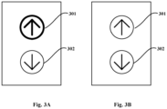
- FIGS. 3A and 3B show an example of status of indicators before and after an elevator car arrives at a floor where an elevator call-out device is located, respectively.
- the button in the "upward" direction is pressed, so under the control of control unit 103, the indicator 301 corresponding to the upward direction is lit (indicated by a thick solid circle) and the indicator 302 corresponding to the downward direction (indicated by a thin solid circle) is in the off state.
- the indicator 301 corresponding to the upward direction is off and the indicator 302 corresponding to the downward direction remains in the off state.
- FIGS. 4A and 4B show another example of status of indicators before and after an elevator car arrives at a floor where an elevator call-out device is located, respectively.
- the buttons in the "upward” and “downward” directions are pressed, so under the control of control unit 103, both indicators 401 and 402 are lit (indicated by thick solid circles) as shown in FIG. 4A .
- both indicators 401 and 402 are lit (indicated by thick solid circles) as shown in FIG. 4A .
- the elevator car will continue to move upward after stopping according to a dispatching command of the elevator controller, when the elevator car arrives at the floor where the elevator call-out device is located, under the control of control unit 103, as shown in Fig.
- the indicator 401 corresponding to the upward direction will be off (indicating that a upward call request is satisfied), while the indicator corresponding to the downward direction remains in the normally lit state (indicating that a downward call request is not yet satisfied). Subsequently, after a passenger enters the car and presses the floor to be reached upward, a door of the elevator car and a landing door will be closed and the elevator car will move upward.
- the service status of the elevator indicated by the status of the indicator may be misinterpreted. Specifically, the inventors of the application found through psychological experiments that in the case shown in FIG.
- the control unit adopts the following improved control logic: in response to an event that the elevator car stops at the landing station or floor where the elevator call-out device is located, the indicator corresponding to the direction of movement of the elevator car in which the car will move after stopping is caused into the flashing state (for example, by causing the indicator to be periodically powered on or by continuously supplying power to the indicator with a changing current or voltage), and in response to an event that the door of the elevator car or the door of the landing station where the elevator call-out device is located is closed, the indicator of the call-out button corresponding to the direction of movement of the elevator car in which the car will move after stopping is caused to be switched from the flashing state to the off state.
- the flashing state indicates the service status of the elevator in which a call request in a certain direction (upward or downward) is being satisfied
- the normally lit state indicates the service status of the elevator in which a call request in a certain direction (upward or downward) is not yet satisfied
- the off state indicates the service status of the elevator in which no call request in a certain direction (upward or downward) exists.
- an indication signal that the elevator car stops at the landing station where the elevator call-out device is located may be sent to the control unit of the elevator call-out device by an external device such as an elevator controller or an elevator control cabinet.
- an indication signal that the door of the landing station where the elevator call-out device is located is opened or that the door of the elevator car is opened after arriving at the landing station where the elevator call-out device is located may be sent to the control unit of the elevator call-out device by an external device such as an elevator controller or an elevator control cabinet.
- the indication signal described here should be broadly understood as not only including the signals that directly indicate the elevator car stops at the landing station, the door of the elevator car and the landing door are closed (such as the status signals sent by the elevator controller to indicate the opening and closing status of the car door, etc.), but also including the signals that indirectly indicate the elevator car stops at the landing station, the door of the elevator car and the landing door are closed (such as the command to turn off the indicator sent by the elevator controller to the elevator call-out device).
- FIGS. 5A and 5B show another example of status of indicators before and after an elevator car arrives at a floor where an elevator call-out device is located, respectively.
- FIG. 5A similar to FIG. 3A , it is assumed that the button in the "upward" direction is pressed, so the indicator 501 corresponding to the upward direction is lit (indicated by a thick solid circle) and the indicator 502 corresponding to the downward direction is in the off state.
- FIG. 5B when the elevator car arrives at the floor where the elevator call-out device is located, although the indicator 502 remains in the off state, unlike the status of the indicator shown in FIG. 3B , in FIG.
- the indicator 501 corresponding to the upward direction goes into a flashing state (indicated by a dashed circle). Subsequently, after a passenger enters the car and presses the floor to be reached upward, a door of the elevator car and a landing door will be closed and the elevator car will move upward. At this time, the indicator 501 will be switched from the flashing state to the off state.
- FIGS. 6A and 6B show another example of status of indicators before and after an elevator car arrives at a floor where an elevator call-out device is located, respectively.
- FIG. 6A in this example, similar to FIG. 4A , it is assumed that both buttons in the "upward” and “downward” directions are pressed, and thus the two indicators 601 and 602, representing the “upward” and “downward” directions, are both lit (indicated by the thick solid circles). Then referring to Fig.
- the indicator 602 corresponding to the downward direction will enter the flashing state to indicate that the upward call request is being satisfied. Subsequently, after a passenger enters the car and presses the floor to be reached upward, a door of the elevator car and a landing door will be closed and the elevator car will move upward. At this time, the indicator 601 will be switched from the flashing state to the off state.
- the elevator controller when an elevator car stops at the landing station, the elevator controller will send a command to the elevator call-out device to bring the visual sign corresponding to the direction of movement of the car after stopping into an off state.
- this command is interpreted as an indication signal that the elevator car stops at the landing station where the elevator call-out device is located, the improved control logic described above can be implemented without changing the control logic on the elevator controller side.
- call-out button indicator is only one example of a visual sign used to indicate the direction of elevator movement.
- visual signs include, but are not limited to, arrival indicator and upward and downward markers displayed on the display screen (e.g., arrow markers displayed on the display screen 203 of FIGS. 2A and 2B ), etc.
- the flashing state described herein should be broadly understood as a state in which the visual sign provides a dynamic display effect.
- this dynamic display effect may be presented by a variation of the luminous intensity of the visual sign within a set range (e.g., 30%-100% of the maximum luminous intensity), which may be achieved, for example, by providing a changing current or voltage to the indicator of the call-out button.
- the dynamic display effect is reflected as a variation in the color of the visual signs, such as the alternate illumination of a plurality of indicators with different colors (which all correspond to the same call-out button).
- respiratory frequency varies with age, gender and physiological state, there is usually a normal range for a large number of individuals.
- the inventors of the present application have found through research that when the luminous intensity or frequency of color change of the visual sign is set within the normal range of respiratory frequency (e.g., 12-20 times/minute), it can significantly improve the subject's attention to the visual sign without causing discomfort to the subject.
- FIG. 7 is a schematic block diagram of a typical elevator system.
- an elevator system 700 includes an elevator controller 710, an elevator car 720, and a plurality of elevator call-out devices 730.
- Each elevator call-out device is provided at the corresponding landing station or floor to receive the user's call request and display service status of the elevator.
- the elevator controller 710 generates operation instructions for the elevator car based on the call requests received from the elevator call-out devices 730.
- the elevator call-out devices 730 may have various structures and features of the embodiments of the present application described above with the help of the accompanying drawings, in particular, the control units of the elevator call-out devices use the improved control logic described above to indicate the service status of the elevator.
- FIG. 8 is a flowchart of a method for indicating a service status of an elevator in accordance with some embodiments of the present application. Exemplarily, each step of the method shown in FIG. 8 is described below using the elevator call-out device shown in FIG. 1 as an example.
- Step 801 The control unit 103 of the elevator call-out device 100, upon receiving a request to make the elevator car move upward or downward relative to the landing station where the elevator call-out device is located, causes the indicator of the call-out button corresponding to the requested direction of movement to enter a normally lit state. For example, if a request for upward movement is received, the control unit 103 causes the indicator corresponding to upward movement to be in the normally lit state.
- the control unit 103 may determine whether a request is received and the type of request (upward movement or downward movement) based on the state of the call-out button 101 (e.g., buttons 201 and 202). Exemplarily, when the call-out button is pressed or an object is hovered near the call-out button, a trigger signal is generated at the control unit 103 (e.g., a high level signal is applied to the I/O port of the chip used to implement the control unit function), whereby the control unit 103 may determine the presence and type of the request and light the corresponding indicator by turning on the power supply Vcc.
- a trigger signal is generated at the control unit 103 (e.g., a high level signal is applied to the I/O port of the chip used to implement the control unit function), whereby the control unit 103 may determine the presence and type of the request and light the corresponding indicator by turning on the power supply Vcc.
- the visual sign (e.g., indicator of the call-out button) may also be brought into the normally lit state in the following manner.
- the control unit 103 first receives a command from a device (e.g., an elevator controller) located outside the elevator call-out device that indicates the indicator to be switched to the normally lit state; the control unit 103 then switches the indicator indicated by the command from the off state to the normally lit state (e.g., by turning on the power supply Vcc to light the indicator).
- a device e.g., an elevator controller
- a passenger sends a call request via a personal terminal device such as a cell phone, a smart watch and smart glasses, and a device located outside the elevator call-out device (such as an elevator controller) receives the call request and generates a corresponding control command to control the operation of the elevator car and instructs the elevator call-out device to present the corresponding information about the service status of the elevator.
- a personal terminal device such as a cell phone, a smart watch and smart glasses
- a device located outside the elevator call-out device such as an elevator controller
- Step 802 The control unit 103 judges whether there is an event that the elevator car stops at the landing station where the elevator call-out device 100 is located. If it exists, it proceeds to step 803, otherwise it continues to perform the judgment operation.
- an indication signal that the elevator car stops at the landing station where the elevator call-out device is located or an indication signal that the door of the landing station where the elevator call-out device is located is opened or that the door of the elevator car is opened after arriving at the landing station may be sent to the control unit of the elevator call-out device by an elevator controller or an elevator control cabinet.
- Step 803 The control unit 103 causes the indicator of the call-out button corresponding to the direction of movement of the elevator car, in which the car will move after stopping, to enter a flashing state.
- the indicator 502 corresponding to the downward direction remains in the off state while the indicator 501 corresponding to the upward direction enters the flashing state.
- the indicator 602 corresponding to the downward direction remains in the normally lit state while the indicator 601 corresponding to the upward direction will enter the flashing state.
- the flashing state can be achieved by providing a changing current or voltage to the indicator of the call-out button, or by lighting a plurality of indicators with different colors (which all correspond to the same call-out button) alternately.
- the luminous intensity or frequency of color change of the indicator can be set within the normal range of respiratory frequency to improve the passenger's attention to the indicator without causing discomfort.
- Step 804 The control unit 103 judges whether there is an event that the door of the elevator car or the door of the landing station where the elevator out-call device is located is closed. If it exists, it proceeds to step 805, otherwise it continues to perform the judgment operation.
- Various ways may be used to notify the control unit of an event that the door of the elevator car or the door of the landing station where the elevator call-out device is located is closed, such as the elevator controller or the elevator control cabinet sending an indication signal to the control unit that the door of the elevator car or the door of the landing station is closed.
- step 805 it is also possible to replace the above judgment with a judgment of whether the stay of the elevator car at the landing station where the elevator call-out device 100 is located exceeds a preset duration. If it exceeds, it proceeds to step 805, otherwise, it continues to wait.
- Step 805 The control unit 103 causes the indicator of the call-out button corresponding to the direction of movement of the elevator car after stopping switch from the flashing state to the off state.
- the indicator 501 corresponding to the upward direction will switch to the off state under the control of control unit 103.
- the indicator 602 corresponding to the downward direction remains in the normally lit state while the indicator 601 corresponding to the upward direction switches from the flashing state to the off state.
- a computer-readable storage medium on which a computer program is stored.
- the program is executed by the processor, one or more steps contained in the method described above with the help of FIG. 8 may be realized.
- the computer-readable storage medium referred to in the application includes various types of computer storage media, and may be any available medium that may be accessed by a general-purpose or special-purpose computer.
- the computer-readable storage medium may include RAM, ROM, EPROM, E2PROM, registers, hard disks, removable disks, CD-ROM or other optical disk storage, magnetic disk storage or other magnetic storage devices, or any other transitory or non-transitory medium that may be used to carry or store a desired program code unit in the form of instructions or data structures and that may be accessed by a general-purpose or special-purpose computer or a general-purpose or special-purpose processor.
- Disks as used herein usually copy data magnetically, while discs use lasers to optically copy data.
- An exemplary storage medium is coupled to the processor such that the processor can read and write information from and to the storage medium.
- the storage medium may be integrated into the processor.
- the processor and the storage medium may reside in the ASIC.
- the ASIC may reside in the user terminal.
- the processor and the storage medium may reside as discrete components in the user terminal.
Landscapes
- Engineering & Computer Science (AREA)
- Automation & Control Theory (AREA)
- Computer Networks & Wireless Communication (AREA)
- Indicating And Signalling Devices For Elevators (AREA)
- Elevator Control (AREA)
Applications Claiming Priority (1)
| Application Number | Priority Date | Filing Date | Title |
|---|---|---|---|
| CN202210323808.8A CN116924172A (zh) | 2022-03-30 | 2022-03-30 | 用于指示电梯服务状态的方法和电梯外呼装置 |
Publications (1)
| Publication Number | Publication Date |
|---|---|
| EP4253295A1 true EP4253295A1 (fr) | 2023-10-04 |
Family
ID=84361633
Family Applications (1)
| Application Number | Title | Priority Date | Filing Date |
|---|---|---|---|
| EP22209475.7A Pending EP4253295A1 (fr) | 2022-03-30 | 2022-11-24 | Procédé et dispositif de mise en communication d'ascenseur pour indiquer l'état de service d'un ascenseur |
Country Status (3)
| Country | Link |
|---|---|
| US (1) | US20230312304A1 (fr) |
| EP (1) | EP4253295A1 (fr) |
| CN (1) | CN116924172A (fr) |
Citations (3)
| Publication number | Priority date | Publication date | Assignee | Title |
|---|---|---|---|---|
| US4600087A (en) * | 1983-07-22 | 1986-07-15 | Mitsubishi Denki Kabushiki Kaisha | Apparatus for registering elevator call |
| US20180022572A1 (en) * | 2015-03-26 | 2018-01-25 | Mitsubishi Electric Corporation | Elevator group management system |
| CN107814282A (zh) * | 2016-09-13 | 2018-03-20 | 崇友实业股份有限公司 | 电梯按钮盘及其显示方法 |
-
2022
- 2022-03-30 CN CN202210323808.8A patent/CN116924172A/zh active Pending
- 2022-11-21 US US17/991,305 patent/US20230312304A1/en active Pending
- 2022-11-24 EP EP22209475.7A patent/EP4253295A1/fr active Pending
Patent Citations (3)
| Publication number | Priority date | Publication date | Assignee | Title |
|---|---|---|---|---|
| US4600087A (en) * | 1983-07-22 | 1986-07-15 | Mitsubishi Denki Kabushiki Kaisha | Apparatus for registering elevator call |
| US20180022572A1 (en) * | 2015-03-26 | 2018-01-25 | Mitsubishi Electric Corporation | Elevator group management system |
| CN107814282A (zh) * | 2016-09-13 | 2018-03-20 | 崇友实业股份有限公司 | 电梯按钮盘及其显示方法 |
Also Published As
| Publication number | Publication date |
|---|---|
| CN116924172A (zh) | 2023-10-24 |
| US20230312304A1 (en) | 2023-10-05 |
Similar Documents
| Publication | Publication Date | Title |
|---|---|---|
| US11449119B2 (en) | Method for displaying content in expandable screen area and electronic device supporting the same | |
| US9785217B2 (en) | System and method for low power input object detection and interaction | |
| EP0817000A1 (fr) | Dispositif de pointage déformable pour écrans tactiles | |
| JPH06119090A (ja) | 省電力制御方式 | |
| US20120113151A1 (en) | Display apparatus and display method | |
| US20210232233A1 (en) | Hand Gestures Recognition over a Switch Based Keyboard | |
| KR20150025548A (ko) | 전자 장치의 상태 표시 장치, 방법 및 컴퓨터 판독 가능한 기록 매체 | |
| EP4253295A1 (fr) | Procédé et dispositif de mise en communication d'ascenseur pour indiquer l'état de service d'un ascenseur | |
| CN104142742A (zh) | 触控电子设备和触控电子设备的触控方式切换方法 | |
| US12493366B2 (en) | Information handling system touch function row with gesture inputs | |
| CN214828131U (zh) | 一种非接触式电梯控制面板 | |
| JP7689068B2 (ja) | エレベーターシステム | |
| EP4286313A1 (fr) | Procédé et panneau de commande pour indiquer l'état de service d'un ascenseur | |
| CN111459357A (zh) | 在阅读终端中显隐快捷键的方法、终端及计算机存储介质 | |
| CN102398810B (zh) | 电梯装置 | |
| JP2023115688A (ja) | エレベータ制御装置、制御方法およびプログラム | |
| WO2026086250A1 (fr) | Clavier dédié pour inspection de sécurité, et système d'inspection de sécurité | |
| US20180292924A1 (en) | Input processing apparatus | |
| US12373044B1 (en) | Information handling system capacitive touch function row with on-screen-display user interface | |
| US12236084B1 (en) | Information handling system touch function row with sliding presentation of function icons | |
| US20250244870A1 (en) | Information handling system touch function row at flexible display film folded over hinge | |
| US12468440B2 (en) | Information handling system touch function row with secondary display and coordinated presentation on main display | |
| US20160132193A1 (en) | Cabin management system using wearable display device | |
| US20250244867A1 (en) | Information handling system touch function row with hover detection and coordinated presentation on main display | |
| CN220312459U (zh) | 具有光面按键的磨砂面膜式机床操作面板 |
Legal Events
| Date | Code | Title | Description |
|---|---|---|---|
| PUAI | Public reference made under article 153(3) epc to a published international application that has entered the european phase |
Free format text: ORIGINAL CODE: 0009012 |
|
| STAA | Information on the status of an ep patent application or granted ep patent |
Free format text: STATUS: THE APPLICATION HAS BEEN PUBLISHED |
|
| AK | Designated contracting states |
Kind code of ref document: A1 Designated state(s): AL AT BE BG CH CY CZ DE DK EE ES FI FR GB GR HR HU IE IS IT LI LT LU LV MC ME MK MT NL NO PL PT RO RS SE SI SK SM TR |
|
| STAA | Information on the status of an ep patent application or granted ep patent |
Free format text: STATUS: REQUEST FOR EXAMINATION WAS MADE |
|
| 17P | Request for examination filed |
Effective date: 20240328 |
|
| RBV | Designated contracting states (corrected) |
Designated state(s): AL AT BE BG CH CY CZ DE DK EE ES FI FR GB GR HR HU IE IS IT LI LT LU LV MC ME MK MT NL NO PL PT RO RS SE SI SK SM TR |
|
| STAA | Information on the status of an ep patent application or granted ep patent |
Free format text: STATUS: EXAMINATION IS IN PROGRESS |
|
| 17Q | First examination report despatched |
Effective date: 20240912 |