EP4253625A1 - Machine à tricoter rectiligne et son mécanisme de sélection des aiguilles - Google Patents
Machine à tricoter rectiligne et son mécanisme de sélection des aiguilles Download PDFInfo
- Publication number
- EP4253625A1 EP4253625A1 EP23164196.0A EP23164196A EP4253625A1 EP 4253625 A1 EP4253625 A1 EP 4253625A1 EP 23164196 A EP23164196 A EP 23164196A EP 4253625 A1 EP4253625 A1 EP 4253625A1
- Authority
- EP
- European Patent Office
- Prior art keywords
- needle
- knitting
- selection
- select jack
- selector
- Prior art date
- Legal status (The legal status is an assumption and is not a legal conclusion. Google has not performed a legal analysis and makes no representation as to the accuracy of the status listed.)
- Granted
Links
Images



Classifications
-
- D—TEXTILES; PAPER
- D04—BRAIDING; LACE-MAKING; KNITTING; TRIMMINGS; NON-WOVEN FABRICS
- D04B—KNITTING
- D04B15/00—Details of, or auxiliary devices incorporated in, weft knitting machines, restricted to machines of this kind
- D04B15/32—Cam systems or assemblies for operating knitting instruments
-
- D—TEXTILES; PAPER
- D04—BRAIDING; LACE-MAKING; KNITTING; TRIMMINGS; NON-WOVEN FABRICS
- D04B—KNITTING
- D04B15/00—Details of, or auxiliary devices incorporated in, weft knitting machines, restricted to machines of this kind
- D04B15/32—Cam systems or assemblies for operating knitting instruments
- D04B15/36—Cam systems or assemblies for operating knitting instruments for flat-bed knitting machines
- D04B15/362—Cam systems or assemblies for operating knitting instruments for flat-bed knitting machines with two needle beds in V-formation
- D04B15/365—Cam systems or assemblies for operating knitting instruments for flat-bed knitting machines with two needle beds in V-formation with provision for loop transfer from one needle bed to the other
-
- D—TEXTILES; PAPER
- D04—BRAIDING; LACE-MAKING; KNITTING; TRIMMINGS; NON-WOVEN FABRICS
- D04B—KNITTING
- D04B15/00—Details of, or auxiliary devices incorporated in, weft knitting machines, restricted to machines of this kind
- D04B15/66—Devices for determining or controlling patterns ; Program-control arrangements
- D04B15/68—Devices for determining or controlling patterns ; Program-control arrangements characterised by the knitting instruments used
- D04B15/70—Devices for determining or controlling patterns ; Program-control arrangements characterised by the knitting instruments used in flat-bed knitting machines
Definitions
- the present invention relates to a flatbed knitting machine provided with needle selection mechanisms mounted on a carriage configured to reciprocate along a longitudinal direction of needle beds, for selecting knitting needles to perform knitting operation with the knitting needles.
- the carriage which reciprocates along the longitudinal direction of the needle beds is equipped with the cam systems which drive the knitting needles to perform knitting operation, and the needle selection mechanisms for selecting the knitting needles to be driven.
- At least a pair of front and rear needle beds are disposed to face each other across a needle bed gap.
- the knitting needles are housed in a plurality of needle grooves arranged in parallel at a constant pitch along the longitudinal direction of the needle beds to slide in the needle grooves and are driven in the direction of advancing to and retracting from the needle bed gap.
- the selection of the knitting needle is reflected in the protruding state of the butt disposed in the knitting needle from the needle groove.
- the basic knitting operation of the knitting needle includes three types: knit, tuck, and miss, and the needle selection mechanism is configured to basically select a target knitting needle according to the selection out of the three types in the entry side of the cam system (refer to, for example, Patent Literatures 1, 2).
- the knitting needle has a hook for forming a knitted stitch at the tip thereof on the needle bed gap side, and a selector and a select jack for receiving the selection made in the needle selection mechanism on the tail part side apart from the needle bed gap.
- the selector is driven to guide the select jack to one of three positions, for example, a B-position, an H-position, and an A-position, in response to the selection made twice.
- Presser groups are arranged in the plurality of positions of the select jack so as to press and sink the select jack into the needle groove as necessary.
- the Patent Literature 1 discloses that the selection of a selector is performed by whether the selection butt disposed in the selector is pressed.
- the Patent Literature 2 discloses the technique for replacing an engaging part for driving a select jack after the selection of the selector made in the first time and the second time.
- the technique in the case of guiding of the select jack to the A-position in response to the selection made twice, makes the select jack to be guided to the H-position in the first time, and thereafter replaces the engaging part via which the selector drives the select jack.
- the replacing of the engaging part shortens an idling distance at the time when the selector guides the select jack from the H-position to the A-position in the second time, resulting in contributing to improvement of knitting efficiency.
- the stitch cam disposed in a cam system to draw and retract the knitting needle from the needle bed gap is formed with difference in height on its drawing cam face so as to be lower in the rear, and the butt disposed in the knitting needle is made to protrude with changed amounts according to the height.
- This allows to perform the second-stitch operation of changing the drawing amounts of the knitting needle drawing the yarn fed to the hook thereof at the needle bed gap to form a knitted stitch in changed sizes.
- a stitch may be formed to be loose or tight, respectively.
- partial change of the cam systems or the presser groups enables the split knit operation of forming a split stitch by transferring an old loop to the hook of a knitting needle in the facing needle bed instead of knocking-over, in the formation of a stitch.
- a needle selection mechanism increases in size in the longitudinal direction of the needle bed along which a carriage reciprocates, and in the advancing-and-retracting direction of the knitting needles.
- the needle selection mechanism increases in size, the carriage for mounting increases in size, and the moving stroke becomes longer in the longitudinal direction of the needle bed.
- the moving stroke of the carriage becomes longer, a movement at the same speed takes longer time, resulting in reduction in the knitting efficiency.
- the carriage Even if a greater number of types of operations are made selectable by switching of the cam systems, or the presser groups, without the increase in the number of times of selection in the needle selection mechanisms, the carriage needs to stop moving before and after switching, and needs to perform a kick back of direction after moving in an idle manner in the reverse direction. A kick back of the carriage also lowers the knitting efficiency.
- the object of the present invention is to provide a flatbed knitting machine which has more options of knitting operation and provides excellent knitting efficiency in the knitting operation in a mixed manner.
- the present invention is a flatbed knitting machine provided with:
- said knitting operation selectable in said exit-side part of said cam system includes second stitch operation of drawing with changed amounts performed by a stitch cam disposed in the cam system to make said knitting needle retract from said needle bed gap.
- needle selection uses a selector and a select jack so that the needle selection is possible to use the basic combination already used.
- an intermediate needle selection system is further able to select knitting needles to be driven by an exit-side part of the cam system, so that this increases options of knitting operation.
- an engaging part of the selector and the select jack is replaced from the first stage in the entry-side needle selection mechanism to the second stage, so that this additionally increases the options of knitting operation.
- a knitting needle for which an A-position is selected in the entry-side needle selection mechanism is once lowered to an H-position by a select jack lowering cam, and thereafter subjected to the selection in the intermediate needle selection mechanism, so that such combination is possible as the A-position is selected in the entry-side part of the cam system and the H-position is selected in the exit-side part.
- the entry-side needle selection mechanism and the intermediate needle selection mechanism provide with a larger number of types of available knitting operation in one moving course of a carriage and improve knitting efficiency in such as mixed manner of knitting operations between basic type and another type.
- two-stage switching is possible in engaging of the selector and the select jack by the pressure, which is applied by a pressing cam, to the select jack.
- a tip part of the selector is engaged with a rear end of a selection butt of the select jack in the first stage and engaged with a rear end of an overhang part in the second stage, and thus the engaging part of the selector may be used commonly.
- the entry-side needle selection mechanism and the intermediate needle selection mechanism it is possible by the entry-side needle selection mechanism and the intermediate needle selection mechanism to avoid size increase of the cam system and the carriage in the longitudinal direction of a needle bed.
- the intermediate needle selection mechanism makes it possible to mix a second stitch operation in the operation of drawing a knitting needle by a stitch cam.
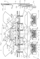
- Fig. 1 to Fig. 5 relate to a configuration of a needle selection mechanism 10 of a flatbed knitting machine 1 in one example according to the present invention.
- Fig. 1 and Fig. 2 areas shown with diagonal lines crossing each other correspond to inclined surfaces.
- Corresponding parts in respective drawings are denoted by a same reference sign, and duplicate descriptions thereof may be omitted. For convenience of explanation, a part not shown in a drawing targeted for description may be described with a reference sign denoted in another drawing.
- Fig. 1 shows a schematic configuration of a flatbed knitting machine 1 including a cam system 2 and a needle selection mechanism 10, as one example according to the present invention.
- the cam system 2 is mounted on a carriage 9 which reciprocates along a longitudinal direction of needle beds of the flatbed knitting machine 1. At least a pair of needle beds is provided with to face each other across a needle bed gap disposed in an above part in the figure.
- Each of the needle beds has needle grooves which are formed to extend in the back-and-forth direction of advancing to and retracting from the needle bed gap.
- the needle grooves are arranged in parallel in the left-and-right direction corresponding to the longitudinal direction of the needle beds.
- a knitting needle 3 is housed in the needle grooves so as to be slidable in the back-and-forth direction, and includes a needle jack 4, a slider 5, the select jack 6, and the selector 7.
- This knitting needle 3 is a compound needle, and the front-end side, which is not shown, of the needle jack 4 is connected to the needle body including a hook on the tip thereof.
- the slider 5 in the front-end side is not shown and has a blade, which opens and closes the hook, is divided into two pieces and advances beyond the hook up to the needle bed gap.
- the needle jack 4, the slider 5 and the select jack 6 has respectively a butt 4b, a butt 5b and a selection butt 6b to be controlled by mechanical actions.
- the selector 7 has an armature 7a to be controlled by magnetic actions and is engaged with the select jack 6 at a tip part 7b.
- the selector 7 further has a drive butt 7c and a lowering butt 7d which will be described later.
- the needle selection mechanism 10 and the cam system 2 have bidirectionality allowing similar symmetrical operation when the carriage 9 reciprocates in the left-and-right direction. The following description is based on the situation where the carriage 9 moves to the left in the drawing along the needle bed as a same knitting course.
- the cam system 2 is divided into an entry-side part 2a and an exit-side part 2b.
- the needle selection mechanism 10 has an entry-side needle selection mechanism 11 configured to perform needle selection for the entry-side part 2a of the cam system 2, an intermediate needle selection mechanism 12 configured to perform needle selection for the exit-side part 2b, and an exit-side needle selection mechanism 13. In the case where the carriage 9 moves to the right, the entry side and the exit side are replaced with each other.
- the entry-side needle selection mechanism 11 makes the selector 7 of the knitting needle 3 select one out of paths 7A, 7H, 7B.
- the path 7A or 7H is selected, the moving stroke toward the needle bed gap occurs for the selector 7.
- the select jack 6 receives the moving stroke from the selector 7 at the engaging part of the rear end of the selection butt 6b and the tip part 7b of the selector 7, and moves toward the needle bed gap.
- the knitting needle 3 to be acted on by the entry side of the cam system 2 is guided so that the selection butt 6b of the select jack 6 is moved to an A-position 6bA or an H-position 6bH by the selector 7 for which the path 7A or the path 7H has been selected, correspondingly.
- a presser group 30 is disposed in the positions where the selection butt 6b may be guided.
- the presser group 30 includes an entry-side A-presser 31a, an exit-side A-presser 31b, an entry-side H-presser 32a, an exit-side H-presser 32b and a B-presser 33.
- the entry-side A-presser 31a is set to non-acting state
- the exit-side A-presser 31b is set to acting state.
- the entry-side H-presser 32a and the exit-side H-presser 32b are fixed to acting state, without changing between acting state and non-acting state.
- the B-presser 33 is fixed to acting state in the entry side through to the exit side.
- the entry-side A-presser 31a and the exit-side A-presser 31b operate in cooperation with each other as an A-presser 31, and the entry-side H-presser 32a and the exit-side H-presser 32b operate in cooperation with each other as an H-presser 32.
- Vertical lines with reference signs a, b, c in the entry-side needle mechanism 11 and vertical lines with reference signs d, e, f in the intermediate needle selection mechanism 12 indicate phases corresponding to positional relations described in Fig. 4 and Fig. 5 , respectively.
- the entry-side needle selection mechanism 11 has a pressing cam 15.
- the pressing cam 15 presses the selection butt 6b to sink the select jack 6 by about half height into the needle groove in a vicinity of the phase a, and thus the tip part 7b of the selector 7 is engaged with the rear end of the selection butt 6b of the select jack 6 having been sunk by about half height.
- the intermediate needle selection mechanism 12 makes the selector 7 of the knitting needle 3 select one out of the paths 7A, 7H, 7B, similarly as the entry-side needle selection mechanism 11.
- the intermediate needle selection mechanism 12 is not provided with, neither the pressing cam 15, nor are any pressers for pressing the selection butt 6b into the needle groove, except only with the B-presser 33 at the B-position in a vicinity of the phase d.
- the select jack 6 for which the B-position has been selected in the entry-side needle selection mechanism 11 continues to be sunk, and the rear end of the selection butt 6b continues to be engaged with the tip part 7b of the selector 7.
- the select jack 6 for which the H-position or the A-position has been selected in the entry-side needle selection mechanism 11 is raised because the selection butt 6b is not pressed, and the engaging part with the tip part 7b of the selector 7 is replaced to the rear end of an overhang part 6c.
- the replacing of the engaging part allows to guide the select jack 6 of the knitting needle 3 on which the cam system 2 acts, to a position closer to the needle bed gap than the position at the time of being guided in the entry-side needle selection mechanism 11, in particular to an F-position 6bF which is newly arranged as a forward position closer to the needle bed gap than the A-position.
- the exit-side needle selection mechanism 13 does not perform the needle selection operation for receiving the action of the cam system 2.
- the needle selection mechanism 10 further has a returning part 16 which returns the select jack 6 to the B-position, and a returning cam 17 which returns the selector 7 to the path 7B.
- a select jack lowering cam 18 is disposed between the entry-side part 2a and the exit-side part 2b of the cam system 2, for lowering the select jack 6 guided to the A-position in response to the selection made by the entry-side needle selection mechanism 11.
- the intermediate needle selection mechanism 12 performs, between the entry-side part 2a and the exit-side part 2b, selection in three stages for the knitting needle 3 in which the select jack 6 has been lowered by the select jack lowering cam 18 from the A-position to the H-position, or the knitting needle 3 for which the H-position or the B-position has been selected in the entry-side needle selection mechanism 11, so as to be driven to one of three paths by the exit-side part 2b.
- the intermediate needle selection mechanism 12 furtherly selects the knitting needle 3, which has been selected in the entry-side needle selection mechanism 11 and been driven by the entry-side part 2a, to be driven by the exit-side part 2b, so that paths with the combined positions selected in the entry side and the exit side are increased.
- the intermediate needle selection mechanism 12 allows additional options of knitting operation by replacing the engaging part of the selector 7 and the select jack 6 in the entry-side needle selection mechanism 11 to another engaging part.
- the knitting needle for which the A-position has been selected in the entry-side needle selection mechanism 11 is once lowered by the select jack lowering cam 18 to the H-position, and thereafter subjected to the selection made by the intermediate needle selection mechanism 12, so that it becomes possible to combine the A-position selected in the entry-side part 2a and the H-position selected in the exit-side part 2b.
- the H-position, the A-position or the F-position is selectable from the H-position, while the B-position, the H-position or the A-position is selectable from the B-position.
- the select jack lowering cam 18 does not lower the select jack 6 from the A-position to the H-position
- the A-position is selected by the entry-side needle selection mechanism 11
- only the A-position or the F-position is selectable by the intermediate needle selection mechanism 12
- the entry-side needle selection mechanism 11 and the intermediate needle selection mechanism 12 provide more options of knitting operation in one moving course of the carriage 9, and excellent knitting efficiency in the knitting operation in a mixed manner, such as of basic knitting operation with another type of knitting operation.
- the cam system 2 includes a needle raising cam 20, a stitch cam 21, and a bridge cam 22. Between the needle raising cam 20 and the bridge cam 22, a path 4bA corresponding to the knitting operation for a knit for the butt 4b of the needle jack 4 is provided.
- the cam system 2 further has a slider cam, configured to act on the butt 5b of the slider 5 at a position closer to the needle bed gap than the bridge cam 22, however it is omitted to show the slider cam.
- a path 4bH and a path 4bB formed to extend across lower positions than the top of the needle raising cam 20 correspond to the knitting operation for a tuck and a miss, respectively.
- the stitch cam 21 has, in the rear of the inclined drawing cam face, a stitch deciding cam face 21b where the cam height is high and a drawing amount is small, and a stitch deciding cam face 21a where the cam height is low and a drawing amount is large, so that second stitch knitting is possible by changing protrusion amount of the butt 4b.
- the intermediate needle selection mechanism 12 allows the selection as to whether to keep the select jack 6 in the B-position or the H-position, or to move the select jack 6 from the B-position to the H-position or the A-position, or from the H-position to the A-position or the F-position.
- the butt 4b of the needle jack 4 is switched between the path 4bA for the knit and the path 4bH for the tuck at the entry side, and between the path 4ba for normal stitch which has relatively fine stitch and the path 4bA for loose stitch which has relatively loose stitch at the exit side.
- the entry-side H-presser 32a and the exit-side A-presser 31b press the selection butt 6b of the select jack 6, so that such path switching for knitting is performed.
- the exit-side H-presser 32b also presses the selection butt 6b, the pressure does not act thereon due to phase relation between the exit-side H-presser 32b and the exit-side part 2b of the cam system 2. Accordingly, looseness of a stitch is selectable in the manner that the H-position is set for the selection of the tuck and the A-position is set for the selection of the knit by the entry-side needle selection mechanism 11, and that the A-position is set for the selection of the normal stitch and the H-position is set for the selection of the loose stitch by the intermediate needle selection mechanism 12.
- the F-position is also selectable by the intermediate needle selection mechanism 12, and thus the F-position may be set for the knitting operation of a split knit, as an example.
- the compound needle in which the blade disposed on the tip side of the slider 5 opens and closes the hook is used as the knitting needle 3, such knitting operation is allowed in a manner that a split knit operation is mixed with a second stitch of the tuck and the knit, as disclosed in JP5330249B by the present applicants.
- the slider cam not illustrated configured to act on the butt 5b of the slider 5 is provided with a guide path for keeping the blade in the state of reaching to the needle bed gap, in the formation of a knitted stitch.
- a slider cam is provided with a knit presser which presses the auxiliary butt provided in front of the butt 5b of the slider 5.
- such split knit operation is made possible by selecting the A-position in the entry-side needle selection mechanism 11 and by selecting the F-position in the intermediate needle selection mechanism 12.
- the selection of the B-position in both the entry-side needle selection mechanism 11 and the intermediate needle selection mechanism 12 results in the miss operation.
- a combination of the A-position raised from the B-position may be possible, so that the combination allows a secondary knit drawing operation for secondarily drawing, by the exit-side stitch cam 21, the knitted stitch having already been knitted and hooked by the knitting needle.
- the secondary knit drawing operation prevents the knitted stitch from being excessively reduced in size due to drawing of knitting yarn in the next knitting operation.
- Fig. 2 shows a partial configuration of the cam system 2 including the configurations of the entry-side needle selection mechanism 11 and the intermediate needle selection mechanism 12 shown in Fig. 1 .
- the entry-side needle selection mechanism 11 and the intermediate needle selection mechanism 12 shown in Fig. 1 include attraction actuators 11a, 12a and selector drive cams 11b, 12b, respectively.
- the attraction actuators 11a, 12a allow switching between the state of attracting the armature 7a of the selector 7 by magnetic force and the state of releasing the armature 7a from the attraction state upon selection, at release positions ⁇ , ⁇ corresponding to the phase a.
- the selector drive cam 11b of the entry-side needle selection mechanism 11 moves the drive butt 7c of the selector 7 in the state of being released from the attraction by the attraction actuator 11a along the pre-set path 7A, 7H, or 7B, so as to move the select jack 6 to one of three positions via the engaging part.
- the path 7B corresponds to a base-state position
- the paths 7H, 7A correspond to selection positions.
- the selector drive cam 12b of the intermediate needle selection mechanism 12 also moves the drive butt 7c in the state of being released from the attraction by the attraction actuator 12a along the path 7A, 7H, or 7B, so as to move the select jack 6 to one of not only the positions in the entry-side needle selection mechanism 11 but also an additional position made available by replacing the engaging part. Accordingly, the F-position described above is able to be arranged for the select jack 6.
- the returning cam 17 has a cam face 17a configured to act on the lowering butt 7d of the selector 7 for returning to the path 7B at the exit sides of the selector drive cams 11b, 12b.
- the entry-side A-presser 31a and the exit-side A-presser 31b operate in cooperation to be in acting state and non-acting state, respectively, as the A-presser 31 of a swing type presser as swings upward in non-acting state.
- the entry-side H-presser 32a and the exit-side H-presser 32b are both in acting state and slide to the direction opposite to the moving direction while keeping the distance therebetween.
- a mechanism for such sliding as disclosed in, for example, JP2015-206143A is used. The sliding assures the path through which the selection butt 6b of the select jack 6 from the B-position or the H-position moves upward to the H-position or the A-position.
- the entry-side H-presser 32a and the exit-side H-presser 32b may be set by a large distance in such a configuration even without the sliding mechanism, the size becomes large.
- predetermined knitting operation for such as a tuck requires the action of the entry-side H-presser 32a. Since the action of the exit-side H-presser 32b is not required, the exit-side H-presser 32b is made to retract to the position where knitting operation is not influenced when the selection butt 6b passes by to avoid the interference with the selection butt 6b.
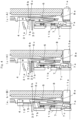
- Fig. 3 shows the engaging part to be replaced in two stages via which the selector 7 moves the select jack 6, with or without pressure applied by the pressing cam 15 arranged in the entry-side needle selection mechanism 11 shown in Fig. 1 .
- the pressing cam 15 acts to press the selection butt 6b of the select jack 6 to sink the select jack 6 by approximately half height into the needle groove, as shown in Fig. 3a .
- the tip part 7b of the selector 7 so pushes forward the rear end of the selection butt 6b in the first stage that the select jack 6 is moved to the A-position or the H-position, correspondingly.
- Fig. 3 shows the engaging part to be replaced in two stages via which the selector 7 moves the select jack 6, with or without pressure applied by the pressing cam 15 arranged in the entry-side needle selection mechanism 11 shown in Fig. 1 .
- the pressing cam 15 acts to press the selection butt 6b of the select jack 6 to sink the select jack 6 by approximately half height into the needle groove, as shown in
- the select jack 6 is raised in the needle groove, and thus the engaging part to be pushed up by the tip part 7b of the selector 7 is replaced from the rear end of the selection butt 6b to the rear end of the overhang part 6c.
- the rear end of the overhang part 6c is positioned behind the tip part 7b in the first stage of the engaging state, and after the selector 7 is returned to the path 7B corresponding to the base-state position in the entry side of the selector drive cam 12b of the intermediate needle selection mechanism 12, the tip part 7b may be positioned behind the rear end of the overhang part 6c.
- the tip part 7b is kept in front of the overhang part 6c even after the selector 7 is returned to the path 7B corresponding to the base-state position, and the tip part 7b continues to be engaged with the rear end of the selection butt 6b.
- the engaging state is the same as in the entry-side needle selection mechanism 11, and the intermediate needle selection mechanism 12 which is also in the first stage of the engaging state allows the selection out of the three positions of the A-position, the H-position or the B-position.
- the Patent Literature 2 discloses such replacing in two stages of the engaging part between the selector and the select jack, as the embodiment 1.
- the Patent Literature 2 further discloses another example for replacing of the engaging part. Such an example is applicable to the present invention.
- Fig. 4 shows the entry-side needle selection mechanism 11, and specifically Fig.4 (a, b-B), Fig. 4 (c-H), and Fig. 4 (c-A) show the positional relations between the selection for the selector 7 and the select jack 6 at the phases a, b, c shown in Fig. 1 , respectively. Both at the phases a, b respectively corresponds to the states, although there exists a difference between before and after, the pressure applied by the pressing cam 15 to the selection butt 6b, there exists no difference in the state where the select jack 6 is sunk by approximately half height into a needle groove 8a of a needle bed 8, as shown in Fig. 3a .
- the selector 7 for which the path 7A or 7H is selected out of the three paths allows to press the select jack 6 in the first stage via the engaging part as shown in Fig. 3(a) .
- the selector 7 for which the path 7B is selected does not push up the select jack 6.
- the selector 7 shown in Fig. 4 (c-A) corresponds to the selection of setting the select jack 6 to the A-position at the release position ⁇ shown in Fig. 2 .
- the selector 7 shown in Fig. 4 (c-H) corresponds to the selection of setting the select jack 6 to the H-position.
- Fig. 5 shows the intermediate needle selection mechanism12, and specifically Fig. 5 (d, e-H), Fig. 5 (f-F) and Fig. 5 (f-A) partially show the positional relations between the selector 7 and the select jack 6 at the phases d, e, f shown in Fig. 1 , respectively.
- the select jack 6 which is free from the pressure applied by the pressing cam 15 to the selection butt 6b, and for which the H-position or the A-position has been selected by the entry-side needle selection mechanism 11 is not sunk in the needle groove 8a of the needle bed 8, so that the selector 7 for which the path 7A or 7H is selected out of the three paths allows to push up the select jack 6 via the engaging part in the second stage as shown in Fig. 3(b) .
- the selector 7 for which the path 7B is selected does not push up the select jack 6.
- the selector 7 shown in Fig. 5 (d, e-H) to is in the base state, and the select jack 6 is in the H-position.
- the select jack 6 When selection is made so that the armature 7a of the selector 7 is released from the attraction actuator 12a at the release position ⁇ , the select jack 6 is guided to the F-position at the phase f.
- the selection for the selector 7 at the release position ⁇ allows to guide the select jack 6 to the A-position.
- the selector 7 for which the path 7A or 7H is selected out of the three paths may guide the select jack 6 for which the B-position is selected by the entry-side needle selection mechanism 11, is able to guide the select jack 6 to the H-position or the A-position.
- the retracting of the exit-side H-presser 32b assures the path for the selection butt 6b, so that it is allowed to avoid size increase of the cam system 2 in the longitudinal direction of the needle bed.
- the entry-side needle selection mechanism 11 and the intermediate needle selection mechanism 12 are provided respectively with the attraction actuators 11a, 12a which utilize magnetic force
- needle selection mechanism as disclosed in the Patent Literature 1
- the use of the attraction actuators 11a, 12a allows to avoid size increase in the left-and-right directions, and further allows the arrangement of the intermediate needle selection mechanism 12 in the intermediate position of the existing cam system 2.
- the compound needle is used as the knitting needle 3
- a latch needle may be used alternatively.
- the present applicant discloses split knit operation by use of the latch needle in, for example, JP5913427 , and thus such operation may be added so as to be selectable by the intermediate needle selection mechanism 12.
- a combination other than the selector 7 and the select jack 6 may be subjected to needle selection.
Landscapes
- Engineering & Computer Science (AREA)
- Textile Engineering (AREA)
- Knitting Machines (AREA)
Applications Claiming Priority (1)
| Application Number | Priority Date | Filing Date | Title |
|---|---|---|---|
| JP2022062178A JP7570370B2 (ja) | 2022-04-01 | 2022-04-01 | 横編機 |
Publications (2)
| Publication Number | Publication Date |
|---|---|
| EP4253625A1 true EP4253625A1 (fr) | 2023-10-04 |
| EP4253625B1 EP4253625B1 (fr) | 2025-07-02 |
Family
ID=85775884
Family Applications (1)
| Application Number | Title | Priority Date | Filing Date |
|---|---|---|---|
| EP23164196.0A Active EP4253625B1 (fr) | 2022-04-01 | 2023-03-24 | Machine à tricoter rectiligne et son mécanisme de sélection des aiguilles |
Country Status (4)
| Country | Link |
|---|---|
| EP (1) | EP4253625B1 (fr) |
| JP (1) | JP7570370B2 (fr) |
| KR (1) | KR102865974B1 (fr) |
| CN (1) | CN116892079B (fr) |
Families Citing this family (2)
| Publication number | Priority date | Publication date | Assignee | Title |
|---|---|---|---|---|
| CN117867737B (zh) * | 2024-01-10 | 2026-04-17 | 浙江睿丰智能科技有限公司 | 一种手套机三角系统 |
| CN118814346B (zh) * | 2024-09-20 | 2024-12-10 | 浙江伟焕机械制造股份有限公司 | 双针筒袜机及编织袜口的方法 |
Citations (5)
| Publication number | Priority date | Publication date | Assignee | Title |
|---|---|---|---|---|
| WO2007074944A1 (fr) | 2005-12-27 | 2007-07-05 | Shima Seiki Mfg., Ltd. | Dispositif de selection d’aiguille pour machine de tricotage trame |
| JP5330249B2 (ja) | 2007-09-05 | 2013-10-30 | 株式会社島精機製作所 | 横編機 |
| JP2015206143A (ja) | 2014-04-23 | 2015-11-19 | 株式会社島精機製作所 | プレッサ装置を備えた横編機 |
| JP5913427B2 (ja) | 2014-05-08 | 2016-04-27 | 株式会社島精機製作所 | 割増やし方法 |
| EP3719191A1 (fr) * | 2019-04-05 | 2020-10-07 | Shima Seiki Mfg., Ltd. | Métier à tricoter rectiligne |
Family Cites Families (4)
| Publication number | Priority date | Publication date | Assignee | Title |
|---|---|---|---|---|
| KR100979440B1 (ko) * | 2002-06-26 | 2010-09-02 | 가부시키가이샤 시마세이키 세이사쿠쇼 | 횡편기의 니들 실렉션 장치 |
| JP2009068122A (ja) * | 2007-09-10 | 2009-04-02 | Shima Seiki Mfg Ltd | 横編機およびその選針方法 |
| JP5044530B2 (ja) * | 2008-11-14 | 2012-10-10 | 株式会社日立製作所 | 付着物検査装置及び付着物検査方法 |
| JP7477422B2 (ja) * | 2020-10-02 | 2024-05-01 | 株式会社島精機製作所 | 横編機 |
-
2022
- 2022-04-01 JP JP2022062178A patent/JP7570370B2/ja active Active
-
2023
- 2023-03-24 EP EP23164196.0A patent/EP4253625B1/fr active Active
- 2023-03-30 KR KR1020230041673A patent/KR102865974B1/ko active Active
- 2023-03-31 CN CN202310345846.8A patent/CN116892079B/zh active Active
Patent Citations (6)
| Publication number | Priority date | Publication date | Assignee | Title |
|---|---|---|---|---|
| WO2007074944A1 (fr) | 2005-12-27 | 2007-07-05 | Shima Seiki Mfg., Ltd. | Dispositif de selection d’aiguille pour machine de tricotage trame |
| JP5330249B2 (ja) | 2007-09-05 | 2013-10-30 | 株式会社島精機製作所 | 横編機 |
| JP2015206143A (ja) | 2014-04-23 | 2015-11-19 | 株式会社島精機製作所 | プレッサ装置を備えた横編機 |
| JP5913427B2 (ja) | 2014-05-08 | 2016-04-27 | 株式会社島精機製作所 | 割増やし方法 |
| EP3719191A1 (fr) * | 2019-04-05 | 2020-10-07 | Shima Seiki Mfg., Ltd. | Métier à tricoter rectiligne |
| JP2020169431A (ja) | 2019-04-05 | 2020-10-15 | 株式会社島精機製作所 | 横編機 |
Also Published As
| Publication number | Publication date |
|---|---|
| CN116892079A (zh) | 2023-10-17 |
| JP7570370B2 (ja) | 2024-10-21 |
| KR102865974B1 (ko) | 2025-09-26 |
| JP2023152195A (ja) | 2023-10-16 |
| EP4253625B1 (fr) | 2025-07-02 |
| CN116892079B (zh) | 2026-03-03 |
| KR20230142356A (ko) | 2023-10-11 |
Similar Documents
| Publication | Publication Date | Title |
|---|---|---|
| EP4253625B1 (fr) | Machine à tricoter rectiligne et son mécanisme de sélection des aiguilles | |
| EP3978669B1 (fr) | Tricoteuse rectiligne | |
| KR101329211B1 (ko) | 횡편기 | |
| EP1975295B1 (fr) | Dispositif de selection d'aiguille pour machine de tricotage trame | |
| EP2196569A1 (fr) | Métier à mailles cueillies | |
| EP2471984B1 (fr) | Tricoteuse rectiligne | |
| JP2012132114A (ja) | 横編機の選針装置 | |
| EP3054041B1 (fr) | Machine a tricoter a plateau equipe d'une platine mobile | |
| KR101709944B1 (ko) | 스플릿 스티치 방법 | |
| JPH0138898B2 (fr) | ||
| EP2570535B1 (fr) | Machine à tricoter rectiligne avec une aiguille de type compound, et methode de contrôler un coulisseau pour une machine à tricoter rectiligne | |
| US7412850B2 (en) | Complex cam system | |
| KR101065245B1 (ko) | 편사의 지지절단 방법 및 장치 | |
| CN110678593B (zh) | 横机中的添纱编织方法 | |
| US20060201208A1 (en) | Needle selection device for weft knitting machine | |
| US6688140B2 (en) | Weft knitting machine with transfer mechanism and transferring method | |
| EP3719191A1 (fr) | Métier à tricoter rectiligne | |
| CN221522966U (zh) | 具备压片装置的横机 | |
| CN224160807U (zh) | 一种割圈机用提花装置及编织结构 | |
| CN221320261U (zh) | 具备可动沉降片的横编机 | |
| EP4306698A1 (fr) | Procédé de tricotage d'un tissu tricoté en dentelle au poinçon produit par machine à tricoter rectiligne | |
| CN120119387A (zh) | 一种割圈机用提花装置及编织结构 | |
| JP2012087423A (ja) | 横編機の選針装置 |
Legal Events
| Date | Code | Title | Description |
|---|---|---|---|
| PUAI | Public reference made under article 153(3) epc to a published international application that has entered the european phase |
Free format text: ORIGINAL CODE: 0009012 |
|
| STAA | Information on the status of an ep patent application or granted ep patent |
Free format text: STATUS: THE APPLICATION HAS BEEN PUBLISHED |
|
| AK | Designated contracting states |
Kind code of ref document: A1 Designated state(s): AL AT BE BG CH CY CZ DE DK EE ES FI FR GB GR HR HU IE IS IT LI LT LU LV MC ME MK MT NL NO PL PT RO RS SE SI SK SM TR |
|
| STAA | Information on the status of an ep patent application or granted ep patent |
Free format text: STATUS: REQUEST FOR EXAMINATION WAS MADE |
|
| 17P | Request for examination filed |
Effective date: 20240404 |
|
| RBV | Designated contracting states (corrected) |
Designated state(s): AL AT BE BG CH CY CZ DE DK EE ES FI FR GB GR HR HU IE IS IT LI LT LU LV MC ME MK MT NL NO PL PT RO RS SE SI SK SM TR |
|
| GRAP | Despatch of communication of intention to grant a patent |
Free format text: ORIGINAL CODE: EPIDOSNIGR1 |
|
| STAA | Information on the status of an ep patent application or granted ep patent |
Free format text: STATUS: GRANT OF PATENT IS INTENDED |
|
| INTG | Intention to grant announced |
Effective date: 20240916 |
|
| GRAJ | Information related to disapproval of communication of intention to grant by the applicant or resumption of examination proceedings by the epo deleted |
Free format text: ORIGINAL CODE: EPIDOSDIGR1 |
|
| STAA | Information on the status of an ep patent application or granted ep patent |
Free format text: STATUS: REQUEST FOR EXAMINATION WAS MADE |
|
| GRAP | Despatch of communication of intention to grant a patent |
Free format text: ORIGINAL CODE: EPIDOSNIGR1 |
|
| STAA | Information on the status of an ep patent application or granted ep patent |
Free format text: STATUS: GRANT OF PATENT IS INTENDED |
|
| INTC | Intention to grant announced (deleted) | ||
| INTG | Intention to grant announced |
Effective date: 20250128 |
|
| GRAS | Grant fee paid |
Free format text: ORIGINAL CODE: EPIDOSNIGR3 |
|
| GRAA | (expected) grant |
Free format text: ORIGINAL CODE: 0009210 |
|
| STAA | Information on the status of an ep patent application or granted ep patent |
Free format text: STATUS: THE PATENT HAS BEEN GRANTED |
|
| AK | Designated contracting states |
Kind code of ref document: B1 Designated state(s): AL AT BE BG CH CY CZ DE DK EE ES FI FR GB GR HR HU IE IS IT LI LT LU LV MC ME MK MT NL NO PL PT RO RS SE SI SK SM TR |
|
| REG | Reference to a national code |
Ref country code: GB Ref legal event code: FG4D |
|
| REG | Reference to a national code |
Ref country code: CH Ref legal event code: EP |
|
| REG | Reference to a national code |
Ref country code: DE Ref legal event code: R096 Ref document number: 602023004396 Country of ref document: DE |
|
| REG | Reference to a national code |
Ref country code: IE Ref legal event code: FG4D |
|
| REG | Reference to a national code |
Ref country code: NL Ref legal event code: MP Effective date: 20250702 |
|
| PG25 | Lapsed in a contracting state [announced via postgrant information from national office to epo] |
Ref country code: PT Free format text: LAPSE BECAUSE OF FAILURE TO SUBMIT A TRANSLATION OF THE DESCRIPTION OR TO PAY THE FEE WITHIN THE PRESCRIBED TIME-LIMIT Effective date: 20251103 |
|
| PG25 | Lapsed in a contracting state [announced via postgrant information from national office to epo] |
Ref country code: NL Free format text: LAPSE BECAUSE OF FAILURE TO SUBMIT A TRANSLATION OF THE DESCRIPTION OR TO PAY THE FEE WITHIN THE PRESCRIBED TIME-LIMIT Effective date: 20250702 |
|
| REG | Reference to a national code |
Ref country code: AT Ref legal event code: MK05 Ref document number: 1809352 Country of ref document: AT Kind code of ref document: T Effective date: 20250702 |
|
| PG25 | Lapsed in a contracting state [announced via postgrant information from national office to epo] |
Ref country code: IS Free format text: LAPSE BECAUSE OF FAILURE TO SUBMIT A TRANSLATION OF THE DESCRIPTION OR TO PAY THE FEE WITHIN THE PRESCRIBED TIME-LIMIT Effective date: 20251102 |
|
| PG25 | Lapsed in a contracting state [announced via postgrant information from national office to epo] |
Ref country code: NO Free format text: LAPSE BECAUSE OF FAILURE TO SUBMIT A TRANSLATION OF THE DESCRIPTION OR TO PAY THE FEE WITHIN THE PRESCRIBED TIME-LIMIT Effective date: 20251002 |
|
| REG | Reference to a national code |
Ref country code: LT Ref legal event code: MG9D |
|
| PG25 | Lapsed in a contracting state [announced via postgrant information from national office to epo] |
Ref country code: AT Free format text: LAPSE BECAUSE OF FAILURE TO SUBMIT A TRANSLATION OF THE DESCRIPTION OR TO PAY THE FEE WITHIN THE PRESCRIBED TIME-LIMIT Effective date: 20250702 |
|
| PG25 | Lapsed in a contracting state [announced via postgrant information from national office to epo] |
Ref country code: FI Free format text: LAPSE BECAUSE OF FAILURE TO SUBMIT A TRANSLATION OF THE DESCRIPTION OR TO PAY THE FEE WITHIN THE PRESCRIBED TIME-LIMIT Effective date: 20250702 |
|
| PG25 | Lapsed in a contracting state [announced via postgrant information from national office to epo] |
Ref country code: HR Free format text: LAPSE BECAUSE OF FAILURE TO SUBMIT A TRANSLATION OF THE DESCRIPTION OR TO PAY THE FEE WITHIN THE PRESCRIBED TIME-LIMIT Effective date: 20250702 |
|
| PG25 | Lapsed in a contracting state [announced via postgrant information from national office to epo] |
Ref country code: GR Free format text: LAPSE BECAUSE OF FAILURE TO SUBMIT A TRANSLATION OF THE DESCRIPTION OR TO PAY THE FEE WITHIN THE PRESCRIBED TIME-LIMIT Effective date: 20251003 |
|
| PG25 | Lapsed in a contracting state [announced via postgrant information from national office to epo] |
Ref country code: CZ Free format text: LAPSE BECAUSE OF FAILURE TO SUBMIT A TRANSLATION OF THE DESCRIPTION OR TO PAY THE FEE WITHIN THE PRESCRIBED TIME-LIMIT Effective date: 20250702 Ref country code: SE Free format text: LAPSE BECAUSE OF FAILURE TO SUBMIT A TRANSLATION OF THE DESCRIPTION OR TO PAY THE FEE WITHIN THE PRESCRIBED TIME-LIMIT Effective date: 20250702 |
|
| PG25 | Lapsed in a contracting state [announced via postgrant information from national office to epo] |
Ref country code: LV Free format text: LAPSE BECAUSE OF FAILURE TO SUBMIT A TRANSLATION OF THE DESCRIPTION OR TO PAY THE FEE WITHIN THE PRESCRIBED TIME-LIMIT Effective date: 20250702 |
|
| PG25 | Lapsed in a contracting state [announced via postgrant information from national office to epo] |
Ref country code: PL Free format text: LAPSE BECAUSE OF FAILURE TO SUBMIT A TRANSLATION OF THE DESCRIPTION OR TO PAY THE FEE WITHIN THE PRESCRIBED TIME-LIMIT Effective date: 20250702 Ref country code: BG Free format text: LAPSE BECAUSE OF FAILURE TO SUBMIT A TRANSLATION OF THE DESCRIPTION OR TO PAY THE FEE WITHIN THE PRESCRIBED TIME-LIMIT Effective date: 20250702 |
|
| PG25 | Lapsed in a contracting state [announced via postgrant information from national office to epo] |
Ref country code: RS Free format text: LAPSE BECAUSE OF FAILURE TO SUBMIT A TRANSLATION OF THE DESCRIPTION OR TO PAY THE FEE WITHIN THE PRESCRIBED TIME-LIMIT Effective date: 20251002 |
|
| PG25 | Lapsed in a contracting state [announced via postgrant information from national office to epo] |
Ref country code: ES Free format text: LAPSE BECAUSE OF FAILURE TO SUBMIT A TRANSLATION OF THE DESCRIPTION OR TO PAY THE FEE WITHIN THE PRESCRIBED TIME-LIMIT Effective date: 20250702 |
|
| PG25 | Lapsed in a contracting state [announced via postgrant information from national office to epo] |
Ref country code: SM Free format text: LAPSE BECAUSE OF FAILURE TO SUBMIT A TRANSLATION OF THE DESCRIPTION OR TO PAY THE FEE WITHIN THE PRESCRIBED TIME-LIMIT Effective date: 20250702 |
|
| PG25 | Lapsed in a contracting state [announced via postgrant information from national office to epo] |
Ref country code: DK Free format text: LAPSE BECAUSE OF FAILURE TO SUBMIT A TRANSLATION OF THE DESCRIPTION OR TO PAY THE FEE WITHIN THE PRESCRIBED TIME-LIMIT Effective date: 20250702 |
|
| PGFP | Annual fee paid to national office [announced via postgrant information from national office to epo] |
Ref country code: DE Payment date: 20260102 Year of fee payment: 4 |
|
| PGFP | Annual fee paid to national office [announced via postgrant information from national office to epo] |
Ref country code: TR Payment date: 20260323 Year of fee payment: 4 |
|
| PG25 | Lapsed in a contracting state [announced via postgrant information from national office to epo] |
Ref country code: SK Free format text: LAPSE BECAUSE OF FAILURE TO SUBMIT A TRANSLATION OF THE DESCRIPTION OR TO PAY THE FEE WITHIN THE PRESCRIBED TIME-LIMIT Effective date: 20250702 Ref country code: EE Free format text: LAPSE BECAUSE OF FAILURE TO SUBMIT A TRANSLATION OF THE DESCRIPTION OR TO PAY THE FEE WITHIN THE PRESCRIBED TIME-LIMIT Effective date: 20250702 |