EP4253639B1 - Pompe et lave-vaisselle la comprenant - Google Patents
Pompe et lave-vaisselle la comprenant Download PDFInfo
- Publication number
- EP4253639B1 EP4253639B1 EP23185202.1A EP23185202A EP4253639B1 EP 4253639 B1 EP4253639 B1 EP 4253639B1 EP 23185202 A EP23185202 A EP 23185202A EP 4253639 B1 EP4253639 B1 EP 4253639B1
- Authority
- EP
- European Patent Office
- Prior art keywords
- washing water
- steam
- housing
- pipe
- dishwasher
- Prior art date
- Legal status (The legal status is an assumption and is not a legal conclusion. Google has not performed a legal analysis and makes no representation as to the accuracy of the status listed.)
- Active
Links
Images




Classifications
-
- A—HUMAN NECESSITIES
- A47—FURNITURE; DOMESTIC ARTICLES OR APPLIANCES; COFFEE MILLS; SPICE MILLS; SUCTION CLEANERS IN GENERAL
- A47L—DOMESTIC WASHING OR CLEANING; SUCTION CLEANERS IN GENERAL
- A47L15/00—Washing or rinsing machines for crockery or tableware
-
- A—HUMAN NECESSITIES
- A47—FURNITURE; DOMESTIC ARTICLES OR APPLIANCES; COFFEE MILLS; SPICE MILLS; SUCTION CLEANERS IN GENERAL
- A47L—DOMESTIC WASHING OR CLEANING; SUCTION CLEANERS IN GENERAL
- A47L15/00—Washing or rinsing machines for crockery or tableware
- A47L15/42—Details
-
- A—HUMAN NECESSITIES
- A47—FURNITURE; DOMESTIC ARTICLES OR APPLIANCES; COFFEE MILLS; SPICE MILLS; SUCTION CLEANERS IN GENERAL
- A47L—DOMESTIC WASHING OR CLEANING; SUCTION CLEANERS IN GENERAL
- A47L15/00—Washing or rinsing machines for crockery or tableware
- A47L15/14—Washing or rinsing machines for crockery or tableware with stationary crockery baskets and spraying devices within the cleaning chamber
-
- A—HUMAN NECESSITIES
- A47—FURNITURE; DOMESTIC ARTICLES OR APPLIANCES; COFFEE MILLS; SPICE MILLS; SUCTION CLEANERS IN GENERAL
- A47L—DOMESTIC WASHING OR CLEANING; SUCTION CLEANERS IN GENERAL
- A47L15/00—Washing or rinsing machines for crockery or tableware
- A47L15/42—Details
- A47L15/4214—Water supply, recirculation or discharge arrangements; Devices therefor
- A47L15/4217—Fittings for water supply, e.g. valves or plumbing means to connect to cold or warm water lines, aquastops
-
- A—HUMAN NECESSITIES
- A47—FURNITURE; DOMESTIC ARTICLES OR APPLIANCES; COFFEE MILLS; SPICE MILLS; SUCTION CLEANERS IN GENERAL
- A47L—DOMESTIC WASHING OR CLEANING; SUCTION CLEANERS IN GENERAL
- A47L15/00—Washing or rinsing machines for crockery or tableware
- A47L15/42—Details
- A47L15/4214—Water supply, recirculation or discharge arrangements; Devices therefor
- A47L15/4219—Water recirculation
- A47L15/4221—Arrangements for redirection of washing water, e.g. water diverters to selectively supply the spray arms
-
- A—HUMAN NECESSITIES
- A47—FURNITURE; DOMESTIC ARTICLES OR APPLIANCES; COFFEE MILLS; SPICE MILLS; SUCTION CLEANERS IN GENERAL
- A47L—DOMESTIC WASHING OR CLEANING; SUCTION CLEANERS IN GENERAL
- A47L15/00—Washing or rinsing machines for crockery or tableware
- A47L15/42—Details
- A47L15/4214—Water supply, recirculation or discharge arrangements; Devices therefor
- A47L15/4223—Devices for water discharge, e.g. devices to prevent siphoning, non-return valves
-
- A—HUMAN NECESSITIES
- A47—FURNITURE; DOMESTIC ARTICLES OR APPLIANCES; COFFEE MILLS; SPICE MILLS; SUCTION CLEANERS IN GENERAL
- A47L—DOMESTIC WASHING OR CLEANING; SUCTION CLEANERS IN GENERAL
- A47L15/00—Washing or rinsing machines for crockery or tableware
- A47L15/42—Details
- A47L15/4214—Water supply, recirculation or discharge arrangements; Devices therefor
- A47L15/4225—Arrangements or adaption of recirculation or discharge pumps
-
- A—HUMAN NECESSITIES
- A47—FURNITURE; DOMESTIC ARTICLES OR APPLIANCES; COFFEE MILLS; SPICE MILLS; SUCTION CLEANERS IN GENERAL
- A47L—DOMESTIC WASHING OR CLEANING; SUCTION CLEANERS IN GENERAL
- A47L15/00—Washing or rinsing machines for crockery or tableware
- A47L15/42—Details
- A47L15/4234—Steam generating arrangements
-
- A—HUMAN NECESSITIES
- A47—FURNITURE; DOMESTIC ARTICLES OR APPLIANCES; COFFEE MILLS; SPICE MILLS; SUCTION CLEANERS IN GENERAL
- A47L—DOMESTIC WASHING OR CLEANING; SUCTION CLEANERS IN GENERAL
- A47L15/00—Washing or rinsing machines for crockery or tableware
- A47L15/42—Details
- A47L15/4285—Water-heater arrangements
-
- F—MECHANICAL ENGINEERING; LIGHTING; HEATING; WEAPONS; BLASTING
- F04—POSITIVE - DISPLACEMENT MACHINES FOR LIQUIDS; PUMPS FOR LIQUIDS OR ELASTIC FLUIDS
- F04D—NON-POSITIVE-DISPLACEMENT PUMPS
- F04D29/00—Details, component parts, or accessories
- F04D29/58—Cooling; Heating; Diminishing heat transfer
- F04D29/586—Cooling; Heating; Diminishing heat transfer specially adapted for liquid pumps
- F04D29/588—Cooling; Heating; Diminishing heat transfer specially adapted for liquid pumps cooling or heating the machine
Definitions
- the present invention relates to a pump and a dishwasher including the same, and more particularly, to a pump for transmitting washing water and generating steam and a dishwasher including the pump.
- a dishwasher is a household appliance that removes foreign matter remaining in a tableware by spraying washing water to the tableware.
- the dishwasher typically includes a tub for providing a washing space, a rack which is provided in the tub and accommodates the tableware, a spraying arm for spraying the washing water into the rack, a sump for storing the washing water, and a pump for supplying washing water stored in the sump to the spraying arm.
- the dishwasher performs cleaning by using heated washing water, or performs cleaning or sterilization of the tableware by supplying steam to the tableware.
- Conventional dishwashers typically generate hot water or steam by heating washing water stored in the sump through a heater provided inside the sump.
- the heater since the heater must be exposed to the inside of the sump and be in contact with the washing water, the water level inside the sump must be controlled so that the heater should not be exposed to prevent overheating of the heater.
- the heat transmission is possible only when the heater is in contact with the washing water, there is a problem that foreign matter adheres to the surface of the heater to deteriorate the heat exchange efficiency and the surface of the heater is corroded to decrease the durability.
- a dishwasher that installs a heater in a pump has recently been developed.
- the heater in the pump heats the washing water to generate hot water or steam.
- the performance of the pump is deteriorated as the air is introduced through a passage for discharging the steam, or the steam performance is deteriorated as the steam is discharged through a passage through which the washing water flows.
- the present invention has been made in view of the above problems, and provides a pump and a dishwasher that can generate steam and smoothly discharge the steam without deteriorating the performance of the pump.
- a pump includes: a housing; a washing water inlet pipe to receive washing water; a washing water outlet pipe to discharge the washing water; an impeller to transfer the washing water from the washing water inlet pipe to the washing water outlet pipe; a heater to heat the washing water in the housing and generate steam; and a steam discharge pipe coupled to the washing water outlet pipe to discharge the steam generated by the heater.
- the steam discharge pipe has a cross-sectional area smaller than a cross-sectional area of the washing water outlet pipe.
- a pipe direction of the steam discharge pipe is inclined to an upward direction from a horizontal direction.
- the steam discharge pipe is disposed to be orthogonal to the washing water outlet pipe.
- the pump further includes a partition wall which divides an internal space of the housing to form a positive pressure chamber and a negative pressure chamber, the impeller is disposed in the positive pressure chamber, wherein the washing water inlet pipe is coupled to the negative pressure chamber of the housing, and the washing water outlet pipe is coupled to the positive pressure chamber of the housing.
- the washing water outlet pipe has a stepped portion protruding inward in a portion coupled to the steam discharge pipe.
- the stepped portion protrudes inward in an upstream side of a portion of the washing water outlet pipe coupled to the steam discharge pipe.
- the stepped portion is formed at an entrance of the steam discharge pipe.
- the pump further includes a check valve to close the washing water inlet pipe to prevent the steam generated by the heater from flowing out through the washing water inlet pipe.
- a dishwasher in accordance with another aspect of the present invention, includes: a tub; a spraying arm; a steam supply unit to discharge steam into the tub; a sump; and a pump to supply the washing water stored in the sump to the spraying arm and generate steam to supply to the steam supply unit, wherein the pump having a negative pressure chamber coupled to the sump and a positive pressure chamber coupled to the spraying arm, wherein the steam supply unit is coupled to the positive pressure chamber.
- the pump includes a partition wall to divide an internal space into the negative pressure chamber and the positive pressure chamber.
- the pump includes: a washing water outlet pipe coupled to the positive pressure chamber to discharge the washing water to the spraying arm; and a steam discharge pipe coupled to the washing water outlet pipe and discharges steam to the steam supply unit.
- the steam discharge pipe has a cross-sectional area smaller than a cross-sectional area of the washing water outlet pipe.
- a pipe direction of the steam discharge pipe is inclined to an upward direction from a horizontal direction.
- the steam discharge pipe is disposed to be orthogonal to the washing water outlet pipe.
- the washing water outlet pipe has an upstream side cross-sectional area smaller than a downstream side cross-sectional area based on a portion where the steam discharge pipe is connected.
- the pump includes: a washing water inlet pipe coupled to the negative pressure chamber to introduce the washing water from the sump; and a check valve to close the washing water inlet pipe to prevent steam generated by the heater from flowing out through the washing water inlet pipe.
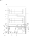
- FIG. 1 is a schematic cross-sectional view of a dishwasher according to an embodiment of the present invention.
- a dishwasher 100 may include a cabinet 1 forming an outer appearance, a tub 11 provided inside the cabinet 1 to accommodate a dishware, a plurality of spraying arms 3 and 5 for spraying washing water into the tub 11, a steam supply unit 6 for discharging steam into the tub 11, a sump 13 for storing washing water, and a pump 8 for supplying the washing water stored in the sump 13 to the plurality of spraying arms 3 and 5 and generating steam to supply to the steam supply unit 6.
- a plurality of racks 191 and 193 for storing dishware may be provided in the tub 11.
- the plurality of racks 191 and 193 may include an upper rack 191 provided in an upper area of the tub 11 and a lower rack 193 provided in a lower area of the tub 11.
- the tub 11 may be opened and closed by a door 16 provided on one side of the cabinet. A user may take out the plurality of racks 191 and 193 from the tub 11 after opening the door 16.
- the plurality of spraying arms 3 and 5 may include an upper arm 3 for spraying washing water to the upper rack 191 and a lower arm 5 for spraying washing water to the lower rack 193.
- the washing water sprayed from the plurality of spraying arms 3 and 5 may be collected into the sump 13.
- the sump 13 may be provided in a lower portion of the tub 11 to store washing water.
- a sump cover 15 may be disposed in an upper side of the sump 13.
- the sump cover 15 may be provided with a recovery hole 151 so that washing water in the tub 11 can pass through the recovery hole 151 and flow into the sump 13.
- the sump 13 may be coupled to an external water source through a water supply channel 135.
- the water supply channel 135 may be opened and closed by a water supply valve 136.
- the washing water stored in the sump 13 may be discharged to the outside of the cabinet 1 through a drainage pipe 137 and a drainage pump 139.
- the washing water stored in the sump 13 may be supplied to the plurality of spraying arms 3 and 5 through the pump 8 and a washing water supply unit 7.
- the washing water supply unit 7 may include a main connection pipe 77 coupled to the pump 8, an upper portion connection pipe 71 connecting the main connection pipe 77 and the upper arm 3, and a lower portion connection pipe 73 connecting the main connection pipe 77 and the lower arm 5.
- the upper portion connection pipe 71 and the lower portion connection pipe 73 may be branched from the main connection pipe 77, and a switching valve 75 for controlling the opening and closing of the upper portion connection pipe 71 and/or the lower portion connection pipe 73 may be provided in a branch point of the upper portion connection pipe 71 and the lower portion connection pipe 73.
- the sump 13 may be coupled to the pump 8 and a supply pipe 131.
- the supply pipe 131 may guide the washing water in the sump 13 to the pump 8.
- the steam supply unit 6 may discharge the steam into the tub 11.
- the steam discharged from the steam supply unit 6 may rise and act on the tableware housed in the plurality of racks 191 and 193.
- the steam supply unit 6 may include a steam nozzle 61 disposed in the tub 11 to discharge steam and a steam supply pipe 63 connecting the steam nozzle 61 and the pump 8.
- the pump 8 may transmit the washing water stored in the sump 13 to the washing water supply unit 7.
- the pump 8 may heat the washing water transmitted to the washing water supply unit 7.
- the pump 8 may suck the washing water stored in the sump 13 and supply to the plurality of spraying arms 3 and 5 through the washing water supply unit 7.
- the pump 8 may generate steam and supply it to the steam supply unit 6.
- the pump 8 may generate steam by heating the washing water stored in the pump 8 without transmitting the washing water.
- the steam generated in the pump 8 may be discharged into the tub 11 through the steam supply unit 6.
- the pump 8 will be described in detail with reference to FIG. 2 and following drawings.
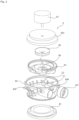
- FIG. 2 is an exploded perspective view of a pump according to an embodiment of the present invention
- FIG. 3 is a schematic cross-sectional view of a pump according to an embodiment of the present invention.
- the pump 8 may include a housing 82 having a cylindrical shape which is fixed inside the cabinet 1, a washing water inlet pipe 841 which is coupled to the housing 82 and into which the washing water flows, a washing water outlet pipe 849 which is coupled to the housing 82 and discharges the washing water, an impeller 85 which is disposed inside the housing 82 to transfer the washing water from the washing water inlet pipe 841 to the washing water outlet pipe 849, a heater 81 coupled to the housing 82 and heats the washing water inside the housing 82 to generate steam, and a steam discharge pipe 845 which is coupled to the washing water outlet pipe 849 and discharges the steam generated by the heater 81.
- the housing 82 may be formed in a cylindrical shape having open top and bottom.
- a housing cover 823 may be coupled to the upper end of the housing 82, and the heater 81 may be coupled to the lower end thereof.
- the housing cover 823 may cover the upper portion of the housing 82, and the housing cover 823 may be provided with a motor 87 for generating a rotational force to rotate the impeller 85.
- a partition wall 84 may be disposed inside the housing 82.
- the partition wall 84 may divide an internal space of the housing 82 into upper and lower portions.
- the partition wall 84 may form a negative pressure chamber C1 and a positive pressure chamber C2 inside the housing 82.
- the negative pressure chamber C1 may be a place where a negative pressure is generated by the rotation of the impeller 85 and the positive pressure chamber C2 may be a place where a positive pressure is generated by the rotation of the impeller 85.
- the negative pressure chamber C1 may be coupled to the sump 13 through the supply pipe 131 and the washing water inlet pipe 841.
- the positive pressure chamber C2 may be coupled to the plurality of spraying arms 3, 5 through the washing water outlet pipe 849 and the washing water supply unit 7.
- the partition wall 84 may be provided with a communication hole 86 for communicating the negative pressure chamber C1 and the positive pressure chamber C2.
- the surface of the partition wall 84 in the positive pressure chamber C2 side may be formed in a volute.
- the impeller 85 may be rotated by the motor 87 to discharge the water in the housing 82 to the outside.
- the impeller 85 may be rotatably disposed in the positive pressure chamber C2.
- the impeller 85 may transfer the washing water introduced from the negative pressure chamber C1 into the positive pressure chamber C2 through the communication hole 86 to the washing water outlet pipe 849.
- the heater 81 may be coupled to the lower end of the housing 82 to form a bottom surface of the housing 82.
- the heater 81 may heat the washing water flowing inside the housing 82 when the impeller 85 rotates.
- the heater 81 may generate steam by heating the washing water in the housing 82 when the impeller 85 stops.
- the washing water inlet pipe 841 may be coupled to the negative pressure chamber C1 side of the housing 82.
- the washing water inlet pipe 841 may be coupled to the supply pipe 131 and the washing water of the sump 13 may flow into the negative pressure chamber C1.
- the washing water inlet pipe 841 may be disposed to protrude outward from the lower side wall of the housing 82.
- the washing water inlet pipe 841 may be arranged in such a manner that a pipe direction is horizontal, so that the washing water flows in the horizontal direction.
- a check valve 842 for opening and closing the washing water inlet pipe 841 is disposed in the washing water inlet pipe 841. Details of the check valve 842 will be described later with reference to FIG. 8 to FIG. 10 .
- the washing water outlet pipe 849 may be coupled to the positive pressure chamber C2 side of the housing 82.
- the washing water outlet pipe 849 may be coupled to the connection pipe 77 of the washing water supply unit 7 so that the washing water of the positive pressure chamber C2 flows out to the connection pipe 77.
- the washing water outlet pipe 849 may be arranged to protrude outward from the upper side wall of the housing 82.
- the washing water outlet pipe 849 may be arranged in such a manner that a pipe direction is horizontal, so that the washing water flows in the horizontal direction.
- the steam discharge pipe 845 is coupled to the positive pressure chamber C2 side of the housing 82.
- the steam discharge pipe 845 may be disposed in various locations of the housing 82 so as to connect the positive pressure chamber C2 of the housing 82 and the steam supply unit 6.
- the steam discharge pipe 845 is coupled to the washing water outlet pipe 849.
- the steam discharge pipe 845 may discharge the steam generated in the housing 82 by the heater 81 to the steam supply unit 6.
- the steam supply unit 6 may be coupled to the positive pressure chamber C2 through the steam discharge pipe 845.
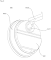
- FIG. 4 is a perspective view of a portion of a pump according to an embodiment of the present invention
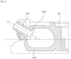
- FIG. 5 is a cross-sectional view taken along line A-A of FIG. 4
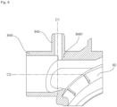
- FIG. 6 is a cross-sectional view taken along line B-B in FIG. 4
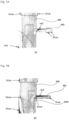
- FIG. 7 is an experimental result of washing water outflow of a pump according to an embodiment of the present invention.
- the cross sectional area of the steam discharge pipe 845 may be smaller than the cross sectional area of the washing water outlet pipe 849.
- the cross sectional area of the steam discharge pipe 845 may be formed to be smaller than the cross sectional area of the washing water outlet pipe 849 to minimize the loss of washing water into the steam discharge pipe 845.
- the steam discharge pipe 845 may be arranged in such a manner that the pipe direction C1 is inclined to the upward direction from the horizontal direction. As shown in FIG. 5 , the pipe direction C1 of the steam discharge pipe 845 may have an included angle i between the horizontal direction and an acute angle. Since the steam in the housing 82 flows in a direction opposite to the direction of gravity, the pipe direction C1 of the steam discharge pipe 845 may be inclined upward so that the loss of steam from the horizontal washing water outlet pipe 849 having a horizontal pipe direction C2 to the washing water supply unit 7 can be minimized.
- the steam discharge pipe 845 may be arranged to be orthogonal to the washing water outlet pipe 849. That is, the steam discharge pipe 845 and the washing water outlet pipe 849 may be arranged in a "T" shape. As shown in FIG. 6 , the pipe direction C1 of the steam discharge pipe 845 may be disposed to be perpendicular to the pipe direction C2 of the washing water outlet pipe 849, so that the loss of the washing water to the steam discharge pipe 845 can be minimized and the loss of steam to the washing water supply unit 7 can be minimized.
- an upstream side cross-sectional area of the washing water outlet pipe 849 may be smaller than a downstream side cross-sectional area based on a portion where the steam discharge pipe 845 is connected.
- the above-described division between the upstream side and the downstream side may be based on the flow direction of the washing water.
- the washing water outlet pipe 849 may be formed with a stepped portion 8491 in which an upstream side, based on the flow direction of the washing water, in a portion where the steam discharge pipe 845 is connected protrudes inward.
- the stepped portion 8491 may be formed at an entrance of the steam discharge pipe 845 based on the steam flow direction.
- the stepped portion 8491 may allow the washing water flowing in the washing water outlet pipe 849 to pass by the steam discharge pipe 845 without being expelled due to inertia.
- FIG. 7A shows a velocity distribution of the washing water when the stepped portion 8491 does not exist
- FIG. 7B shows a velocity distribution of the washing water when the stepped portion 8491 exists.
- the red color indicates a faster washing water speed
- the blue color indicates a slower washing water speed.
- FIG. 8 is a partial exploded perspective view of a pump according to an embodiment of the present invention
- FIG. 9 is a perspective view of a check valve of a pump according to an embodiment of the present invention
- FIG. 10 is an operational example of a check valve of a pump according to an embodiment of the present invention.
- the check valve 842 may open and close the washing water inlet pipe 841 so that the steam which is generated inside the housing 82 by the heater 81 may not flow out through the washing water inlet pipe 841.
- the check valve 842 may be opened when the impeller 85 rotates and may be closed when the impeller 85 stops. That is, the check valve 842 may be opened when the washing water flows and may be closed when the washing water does not flow.
- the check valve 842 may close the washing water inlet pipe 841 during the steam generation of the heater 81 so that the steam generated inside the housing 82 may not flow out to the supply pipe 131 through the washing water inlet pipe 841 from the negative pressure chamber C1.
- the check valve 842 may include a valve body 8421 having a circular segment shape, and a valve fixture 8423 which is coupled so that the valve body 8421 can be rotatable.
- the valve body 8421 may be rotated to open and close the washing water inlet pipe 841.
- the valve body 8421 may rotate toward the negative pressure chamber C1 side when opened.
- the valve body 8421 may be provided with a valve hole 84211 through which a part of the valve fixture 8423 is passed.
- the valve body 8421 may be formed in a circular segment shape so as not to completely block the washwater inlet pipe 841.
- the valve body 8421 may be formed in a circular shape having a cut lower portion so that a part of the lower portion of the washing water inlet pipe 841 is opened when closed. It is required that the washing water in the pump 8 should be drained when the drain pump 139 operates. When the drain pump 139 operates, the washing water in the pump 8 may flow into the supply pipe 131 through a gap between the valve body 8421 and the washing water inlet pipe 841 and may be discharged to the outside through the sump 13 and the drainage pipe 137.
- the valve fixture 8423 may be coupled so that the valve body 8421 can rotate.
- the valve fixture 8423 may be coupled to the washing water inlet pipe 841 so that the valve body 8421 can be arranged to be rotatable for the washing water inlet pipe 841.
- the valve fixture 8423 may be provided with a ring-shaped outlet end connecting unit 84231 and a hinge unit 84233 penetrating the valve hole 84211.
- the outlet end connecting unit 84231 may be formed in a ring shape and may be coupled to a distal end of the washing water inlet pipe 841.
- the circumference of the outlet end connecting unit 84231 may be in contact with the valve body 8421.
- the hinge unit 84233 may pass through the valve hole 84211 and may be coupled to the washing water inlet pipe 841.
- valve body 8421 When the washing water is introduced through the supply pipe 131 during rotation of the impeller 85, the valve body 8421 may be rotated by the flow pressure of the washing water to open the washing water inlet pipe 841. When the impeller 85 is stopped, the valve body 8421 may be in contact with the outlet end connecting unit 84231 to close the washing water inlet pipe 841.
- washing water may be supplied from an external water supply source through the water supply pipe 135 and be stored in the sump 13.
- the motor 87 rotates the impeller 85
- the washing water stored in the sump 13 may flow into the washing water inlet pipe 841 through the supply pipe 131.
- the check valve 842 may be rotated by the flow pressure of the washing water to open the washing water inlet pipe 841.
- the washing water flowed into the washing water inlet pipe 841 may flow into the negative pressure chamber C1 inside the housing 82.
- the washing water in the negative pressure chamber C1 may flow into the positive pressure chamber C2 through the communication hole 86 and then flow into the washing water outlet pipe 849 by the rotation of the impeller 85.
- the heater 81 may heat the washing water flowed into the housing 82.
- the washing water flowed into the washing water outlet pipe 849 may partially flow to the steam discharge pipe 845 but mostly may flow to the washing water supply unit 7.
- the washing water flowed into the washing water supply unit 7 may be sprayed through the upper arm 3 and/or the lower arm 5 depending on the operation of the switching valve 75.
- the washing water sprayed through the upper arm 3 and/or the lower arm 5 may be recovered to the sump 13.
- the washing water in the housing 82 may be heated to generate steam.
- the steam generated in the housing 82 may flow into the washing water outlet pipe 849 and then flow to the steam discharge pipe 845.
- the steam flowing in the washing water outlet pipe 849 can be partially flow to the washing water supply unit 7 but mostly flow to the steam discharge pipe 845.
- the steam flowed into the steam discharge pipe 845 may be discharged into the tub 11 through the steam supply unit 6.
- the steam discharge pipe is coupled to the positive pressure chamber of the pump to prevent the air in the tub from flowing into the pump and to secure the flow rate of the pump.
- the steam discharge pipe is coupled to the washing water outlet pipe to minimize the flowing of the steam generated in the pump to the spraying arm side, thereby improving the steam performance.
- the pump performance is improved by minimizing the discharge of the washing water to the steam discharge pipe.
- the steam generated in the pump is prevented from flowing out to the sump side by the check valve disposed in the washing water inlet pipe, thereby improving the steam performance.
Landscapes
- Engineering & Computer Science (AREA)
- Water Supply & Treatment (AREA)
- Physics & Mathematics (AREA)
- Thermal Sciences (AREA)
- Mechanical Engineering (AREA)
- General Engineering & Computer Science (AREA)
- Washing And Drying Of Tableware (AREA)
- Textile Engineering (AREA)
- Structures Of Non-Positive Displacement Pumps (AREA)
Claims (9)
- Lave-vaisselle (100), comprenant :une cuve (11) ;un bras d'aspersion (3, 5) prévu pour projeter de l'eau de lavage dans la cuve (11) ;une unité d'alimentation en vapeur (6) prévue pour refouler de la vapeur dans la cuve (11) ;un puisard (13) prévu pour stocker de l'eau de lavage ; etune pompe (8) prévue pour refouler de l'eau de lavage stockée dans le puisard (13) vers le bras d'aspersion (3, 5), prévue pour générer de la vapeur, et prévue pour refouler de la vapeur vers l'unité d'alimentation en vapeur (6),où la pompe (8) comprend :un carter (82) ;une conduite d'entrée d'eau de lavage (841) raccordée au carter (82) pour recevoir de l'eau de lavage ;une conduite de sortie d'eau de lavage (849) raccordée au carter pour évacuer l'eau de lavage ;un rotor (85) disposé dans le carter (82) pour transférer l'eau de lavage de la conduite d'entrée d'eau de lavage (841) à la conduite de sortie d'eau de lavage (849) ;un élément chauffant (81) raccordé au carter (82) pour chauffer l'eau de lavage dans le carter (82) et générer de la vapeur ;caractérisé par :une conduite de refoulement de vapeur (845) raccordée à la conduite de sortie d'eau de lavage (849) pour refouler la vapeur générée par l'élément chauffant (81), etoù la pompe comprend une paroi de séparation (84) divisant l'intérieur du carter (82) en une partie supérieure et une partie inférieure, et ayant un trou de communication (86) reliant la partie supérieure et la partie inférieure sur un côté,où le rotor (85) est disposé dans la partie supérieure du carter (82).
- Lave-vaisselle selon la revendication 1, où la surface de section transversale de la conduite de refoulement de vapeur (845) est inférieure à la surface de section transversale de la conduite de sortie d'eau de lavage (849).
- Lave-vaisselle selon la revendication 1 ou la revendication 2, où la surface de section transversale côté amont de la conduite de sortie d'eau de lavage (849) est inférieure à la surface de section transversale côté aval, sur la base d'une partie de connexion de la conduite de refoulement de vapeur (845).
- Lave-vaisselle selon l'une des revendications 1 à 3, où la conduite de sortie d'eau de lavage (849) comprend une partie d'épaulement (8491) faisant saillie d'une surface intérieure de la conduite de sortie d'eau de lavage (849), ladite partie d'épaulement (8491) étant présentée contre la conduite de refoulement de vapeur (845).
- Lave-vaisselle selon la revendication 4, où la partie d'épaulement (8491) est disposée côté amont, sur la base de la direction d'écoulement de l'eau de lavage, dans une partie de connexion de la conduite de refoulement de vapeur (845).
- Lave-vaisselle selon la revendication 4 ou la revendication 5, où la partie d'épaulement (8491) est formée à une entrée de la conduite de refoulement de vapeur (845) sur la base de la direction d'écoulement de vapeur.
- Lave-vaisselle selon la revendication 1, où l'élément chauffant (81) est disposé sous le carter (82), et
où la conduite de sortie d'eau de lavage (849) communique avec la partie supérieure du carter (82). - Lave-vaisselle selon l'une des revendications 1 à 7, où la conduite d'entrée d'eau de lavage (841) communique avec la partie inférieure du carter (82) et fait saillie de la surface circonférentielle du carter (82).
- Lave-vaisselle selon l'une des revendications 1 à 8, où la surface de la paroi de séparation (84) est formée en volute sur le haut.
Applications Claiming Priority (2)
| Application Number | Priority Date | Filing Date | Title |
|---|---|---|---|
| KR1020170034510A KR102359166B1 (ko) | 2017-03-20 | 2017-03-20 | 펌프 및 이를 포함하는 식기세척기 |
| EP18000274.3A EP3378371B1 (fr) | 2017-03-20 | 2018-03-20 | Pompe et lave-vaisselle la comprenant |
Related Parent Applications (2)
| Application Number | Title | Priority Date | Filing Date |
|---|---|---|---|
| EP18000274.3A Division EP3378371B1 (fr) | 2017-03-20 | 2018-03-20 | Pompe et lave-vaisselle la comprenant |
| EP18000274.3A Division-Into EP3378371B1 (fr) | 2017-03-20 | 2018-03-20 | Pompe et lave-vaisselle la comprenant |
Publications (3)
| Publication Number | Publication Date |
|---|---|
| EP4253639A2 EP4253639A2 (fr) | 2023-10-04 |
| EP4253639A3 EP4253639A3 (fr) | 2023-12-20 |
| EP4253639B1 true EP4253639B1 (fr) | 2025-05-07 |
Family
ID=61731582
Family Applications (2)
| Application Number | Title | Priority Date | Filing Date |
|---|---|---|---|
| EP18000274.3A Active EP3378371B1 (fr) | 2017-03-20 | 2018-03-20 | Pompe et lave-vaisselle la comprenant |
| EP23185202.1A Active EP4253639B1 (fr) | 2017-03-20 | 2018-03-20 | Pompe et lave-vaisselle la comprenant |
Family Applications Before (1)
| Application Number | Title | Priority Date | Filing Date |
|---|---|---|---|
| EP18000274.3A Active EP3378371B1 (fr) | 2017-03-20 | 2018-03-20 | Pompe et lave-vaisselle la comprenant |
Country Status (7)
| Country | Link |
|---|---|
| US (2) | US10898053B2 (fr) |
| EP (2) | EP3378371B1 (fr) |
| KR (2) | KR102359166B1 (fr) |
| CN (1) | CN108618719B (fr) |
| AU (2) | AU2018201977B2 (fr) |
| RU (1) | RU2726784C1 (fr) |
| WO (1) | WO2018174515A1 (fr) |
Families Citing this family (20)
| Publication number | Priority date | Publication date | Assignee | Title |
|---|---|---|---|---|
| KR102394266B1 (ko) * | 2017-08-31 | 2022-05-03 | 엘지전자 주식회사 | 세척펌프 및 이를 포함하는 식기세척기 |
| KR102412767B1 (ko) | 2017-08-31 | 2022-06-23 | 엘지전자 주식회사 | 식기세척기 |
| EP3449797B1 (fr) * | 2017-08-31 | 2024-10-16 | Lg Electronics Inc. | Procédé de commande d'un lave-vaisselle |
| CN110966224B (zh) * | 2018-09-30 | 2025-01-10 | 青岛海尔洗碗机有限公司 | 一种洗涤装置的泵 |
| CN110966217B (zh) * | 2018-09-30 | 2025-01-10 | 青岛海尔洗碗机有限公司 | 一种洗涤装置的泵 |
| CN110966222B (zh) * | 2018-09-30 | 2025-01-14 | 青岛海尔洗碗机有限公司 | 一种洗涤装置的泵 |
| CN110966223B (zh) * | 2018-09-30 | 2025-01-10 | 青岛海尔洗碗机有限公司 | 一种洗涤装置的泵 |
| CN110966218B (zh) * | 2018-09-30 | 2025-01-14 | 青岛海尔洗碗机有限公司 | 一种洗涤装置的泵 |
| CN110966220B (zh) * | 2018-09-30 | 2025-01-10 | 青岛海尔洗碗机有限公司 | 一种洗涤装置的泵 |
| CN110966212B (zh) * | 2018-09-30 | 2025-01-10 | 青岛海尔洗碗机有限公司 | 一种洗涤装置的泵 |
| CN110966214B (zh) * | 2018-09-30 | 2025-01-10 | 青岛海尔洗碗机有限公司 | 一种洗涤装置的泵 |
| CN110966213B (zh) * | 2018-09-30 | 2025-01-10 | 青岛海尔洗碗机有限公司 | 一种洗涤装置的泵 |
| CN110966216B (zh) * | 2018-09-30 | 2025-01-14 | 青岛海尔洗碗机有限公司 | 一种洗涤装置的泵 |
| CN110966210B (zh) * | 2018-09-30 | 2025-01-10 | 青岛海尔洗碗机有限公司 | 一种洗涤装置的泵 |
| CN110966211B (zh) * | 2018-09-30 | 2025-01-14 | 青岛海尔洗碗机有限公司 | 一种洗涤装置的泵 |
| CN110966215B (zh) * | 2018-09-30 | 2025-01-14 | 青岛海尔洗碗机有限公司 | 一种洗涤装置的泵 |
| CN110966219B (zh) * | 2018-09-30 | 2025-01-14 | 青岛海尔洗碗机有限公司 | 一种洗涤装置的泵 |
| CN110966221B (zh) * | 2018-09-30 | 2025-01-10 | 青岛海尔洗碗机有限公司 | 一种洗涤装置的泵 |
| USD1079157S1 (en) * | 2021-10-20 | 2025-06-10 | Lg Electronics Inc. | Hot air distributor for dishwasher |
| CN113957672B (zh) * | 2021-10-26 | 2025-03-14 | 陕西康佳智能家电有限公司 | 一种洗衣机的加热装置及洗衣机 |
Family Cites Families (20)
| Publication number | Priority date | Publication date | Assignee | Title |
|---|---|---|---|---|
| US3463173A (en) * | 1965-10-23 | 1969-08-26 | Better Built Mach Corp | Machines for washing laboratory equipment such as flasks,bottles,test tubes and similar articles |
| DE10164503A1 (de) * | 2001-12-28 | 2003-07-17 | Bsh Bosch Siemens Hausgeraete | Geschirrspülmaschine zur Aufnahme von in einem Spülbehälter angeordnetem Reinigungsgut |
| EP1788921B1 (fr) * | 2004-09-14 | 2016-09-14 | LG Electronics Inc. | Lave-vaisselle |
| KR100617161B1 (ko) * | 2004-09-22 | 2006-08-31 | 엘지전자 주식회사 | 식기 세척기의 구동부 |
| KR20060085782A (ko) * | 2005-01-25 | 2006-07-28 | 엘지전자 주식회사 | 식기 세척기의 섬프 구조 |
| KR20080034549A (ko) * | 2006-10-17 | 2008-04-22 | 엘지전자 주식회사 | 식기 세척기의 제어 방법 |
| KR20090013917A (ko) * | 2007-08-03 | 2009-02-06 | 엘지전자 주식회사 | 스팀발생장치 |
| KR101455986B1 (ko) * | 2007-12-10 | 2014-11-03 | 엘지전자 주식회사 | 식기 세척기와 그 제어방법 |
| EP2611349B1 (fr) * | 2010-09-02 | 2015-10-14 | LG Electronics Inc. | Lave-vaisselle |
| US8834648B2 (en) * | 2010-10-21 | 2014-09-16 | Whirlpool Corporation | Dishwasher with controlled rotation of lower spray arm |
| KR20120116326A (ko) | 2011-04-12 | 2012-10-22 | 엘지전자 주식회사 | 식기세척기 및 그의 제어방법 |
| EP2510864B1 (fr) * | 2011-04-12 | 2014-09-03 | LG Electronics Inc. | Lave-vaisselle |
| US20120279536A1 (en) * | 2011-05-04 | 2012-11-08 | Whirlpool Corporation | Dishwasher spray arm with diverting valve |
| CN104074763B (zh) | 2013-03-26 | 2018-01-05 | 珠海格力节能环保制冷技术研究中心有限公司 | 双级增焓转子压缩机及具有其的空调器、热泵热水器 |
| KR20150109944A (ko) * | 2014-03-21 | 2015-10-02 | 엘지전자 주식회사 | 식기세척기 |
| KR102366455B1 (ko) * | 2015-07-20 | 2022-02-23 | 엘지전자 주식회사 | 펌프 및 상기 펌프가 구비된 식기세척기 |
| US10092161B2 (en) * | 2014-08-22 | 2018-10-09 | Lg Electronics Inc. | Pump and dishwasher including the same |
| KR101737845B1 (ko) | 2015-08-03 | 2017-05-19 | 엘지전자 주식회사 | 식기세척기 |
| KR101678442B1 (ko) | 2015-08-04 | 2016-12-06 | 엘지전자 주식회사 | 식기세척기 |
| EP3560406B1 (fr) * | 2017-03-22 | 2021-01-06 | LG Electronics Inc. | Pompe et lave-vaisselle la comprenant |
-
2017
- 2017-03-20 KR KR1020170034510A patent/KR102359166B1/ko active Active
-
2018
- 2018-03-20 CN CN201810228820.4A patent/CN108618719B/zh active Active
- 2018-03-20 EP EP18000274.3A patent/EP3378371B1/fr active Active
- 2018-03-20 RU RU2019133126A patent/RU2726784C1/ru active
- 2018-03-20 EP EP23185202.1A patent/EP4253639B1/fr active Active
- 2018-03-20 WO PCT/KR2018/003219 patent/WO2018174515A1/fr not_active Ceased
- 2018-03-20 US US15/926,036 patent/US10898053B2/en active Active
- 2018-03-20 AU AU2018201977A patent/AU2018201977B2/en active Active
-
2020
- 2020-01-10 AU AU2020200194A patent/AU2020200194B2/en active Active
- 2020-12-18 US US17/126,389 patent/US12408811B2/en active Active
-
2022
- 2022-01-28 KR KR1020220013084A patent/KR102487867B1/ko active Active
Also Published As
| Publication number | Publication date |
|---|---|
| AU2018201977A1 (en) | 2018-10-04 |
| WO2018174515A1 (fr) | 2018-09-27 |
| RU2726784C1 (ru) | 2020-07-15 |
| CN108618719A (zh) | 2018-10-09 |
| CN108618719B (zh) | 2021-04-23 |
| AU2018201977B2 (en) | 2019-10-31 |
| KR102359166B1 (ko) | 2022-02-04 |
| KR102487867B1 (ko) | 2023-01-11 |
| EP4253639A3 (fr) | 2023-12-20 |
| EP3378371B1 (fr) | 2023-08-16 |
| US20210127941A1 (en) | 2021-05-06 |
| AU2020200194B2 (en) | 2021-09-09 |
| US10898053B2 (en) | 2021-01-26 |
| AU2020200194A1 (en) | 2020-01-30 |
| US12408811B2 (en) | 2025-09-09 |
| EP4253639A2 (fr) | 2023-10-04 |
| US20180263459A1 (en) | 2018-09-20 |
| KR20180106340A (ko) | 2018-10-01 |
| EP3378371A1 (fr) | 2018-09-26 |
| KR20220020315A (ko) | 2022-02-18 |
Similar Documents
| Publication | Publication Date | Title |
|---|---|---|
| EP4253639B1 (fr) | Pompe et lave-vaisselle la comprenant | |
| US11553827B2 (en) | Dishwasher | |
| US11737640B2 (en) | Pump and dishwasher comprising the same | |
| EP3466315B1 (fr) | Pompe et lave-vaisselle la comprenant | |
| KR20170010550A (ko) | 펌프 및 상기 펌프가 구비된 식기세척기 | |
| EP3598929B1 (fr) | Lave-vaisselle | |
| KR20170010549A (ko) | 펌프 및 상기 펌프가 구비된 식기세척기 | |
| KR102412768B1 (ko) | 식기세척기 | |
| KR20200012710A (ko) | 식기세척기 | |
| CN110662473B (zh) | 泵和包括该泵的洗碗机 |
Legal Events
| Date | Code | Title | Description |
|---|---|---|---|
| PUAI | Public reference made under article 153(3) epc to a published international application that has entered the european phase |
Free format text: ORIGINAL CODE: 0009012 |
|
| STAA | Information on the status of an ep patent application or granted ep patent |
Free format text: STATUS: THE APPLICATION HAS BEEN PUBLISHED |
|
| AC | Divisional application: reference to earlier application |
Ref document number: 3378371 Country of ref document: EP Kind code of ref document: P |
|
| AK | Designated contracting states |
Kind code of ref document: A2 Designated state(s): AL AT BE BG CH CY CZ DE DK EE ES FI FR GB GR HR HU IE IS IT LI LT LU LV MC MK MT NL NO PL PT RO RS SE SI SK SM TR |
|
| REG | Reference to a national code |
Ref country code: DE Free format text: PREVIOUS MAIN CLASS: D06F0058200000 Ipc: A47L0015420000 Ref country code: DE Ref legal event code: R079 Ref document number: 602018081878 Country of ref document: DE Free format text: PREVIOUS MAIN CLASS: D06F0058200000 Ipc: A47L0015420000 |
|
| PUAL | Search report despatched |
Free format text: ORIGINAL CODE: 0009013 |
|
| AK | Designated contracting states |
Kind code of ref document: A3 Designated state(s): AL AT BE BG CH CY CZ DE DK EE ES FI FR GB GR HR HU IE IS IT LI LT LU LV MC MK MT NL NO PL PT RO RS SE SI SK SM TR |
|
| RIC1 | Information provided on ipc code assigned before grant |
Ipc: D06F 58/20 20060101ALI20231116BHEP Ipc: F04D 29/58 20060101ALI20231116BHEP Ipc: A47L 15/42 20060101AFI20231116BHEP |
|
| STAA | Information on the status of an ep patent application or granted ep patent |
Free format text: STATUS: REQUEST FOR EXAMINATION WAS MADE |
|
| 17P | Request for examination filed |
Effective date: 20240614 |
|
| RBV | Designated contracting states (corrected) |
Designated state(s): AL AT BE BG CH CY CZ DE DK EE ES FI FR GB GR HR HU IE IS IT LI LT LU LV MC MK MT NL NO PL PT RO RS SE SI SK SM TR |
|
| GRAP | Despatch of communication of intention to grant a patent |
Free format text: ORIGINAL CODE: EPIDOSNIGR1 |
|
| STAA | Information on the status of an ep patent application or granted ep patent |
Free format text: STATUS: GRANT OF PATENT IS INTENDED |
|
| INTG | Intention to grant announced |
Effective date: 20241119 |
|
| GRAS | Grant fee paid |
Free format text: ORIGINAL CODE: EPIDOSNIGR3 |
|
| GRAA | (expected) grant |
Free format text: ORIGINAL CODE: 0009210 |
|
| STAA | Information on the status of an ep patent application or granted ep patent |
Free format text: STATUS: THE PATENT HAS BEEN GRANTED |
|
| AC | Divisional application: reference to earlier application |
Ref document number: 3378371 Country of ref document: EP Kind code of ref document: P |
|
| AK | Designated contracting states |
Kind code of ref document: B1 Designated state(s): AL AT BE BG CH CY CZ DE DK EE ES FI FR GB GR HR HU IE IS IT LI LT LU LV MC MK MT NL NO PL PT RO RS SE SI SK SM TR |
|
| REG | Reference to a national code |
Ref country code: GB Ref legal event code: FG4D |
|
| REG | Reference to a national code |
Ref country code: CH Ref legal event code: EP |
|
| REG | Reference to a national code |
Ref country code: DE Ref legal event code: R096 Ref document number: 602018081878 Country of ref document: DE |
|
| REG | Reference to a national code |
Ref country code: IE Ref legal event code: FG4D |
|
| REG | Reference to a national code |
Ref country code: NL Ref legal event code: MP Effective date: 20250507 |
|
| PG25 | Lapsed in a contracting state [announced via postgrant information from national office to epo] |
Ref country code: FI Free format text: LAPSE BECAUSE OF FAILURE TO SUBMIT A TRANSLATION OF THE DESCRIPTION OR TO PAY THE FEE WITHIN THE PRESCRIBED TIME-LIMIT Effective date: 20250507 Ref country code: PT Free format text: LAPSE BECAUSE OF FAILURE TO SUBMIT A TRANSLATION OF THE DESCRIPTION OR TO PAY THE FEE WITHIN THE PRESCRIBED TIME-LIMIT Effective date: 20250908 Ref country code: ES Free format text: LAPSE BECAUSE OF FAILURE TO SUBMIT A TRANSLATION OF THE DESCRIPTION OR TO PAY THE FEE WITHIN THE PRESCRIBED TIME-LIMIT Effective date: 20250507 |
|
| REG | Reference to a national code |
Ref country code: LT Ref legal event code: MG9D |
|
| PG25 | Lapsed in a contracting state [announced via postgrant information from national office to epo] |
Ref country code: GR Free format text: LAPSE BECAUSE OF FAILURE TO SUBMIT A TRANSLATION OF THE DESCRIPTION OR TO PAY THE FEE WITHIN THE PRESCRIBED TIME-LIMIT Effective date: 20250808 Ref country code: NO Free format text: LAPSE BECAUSE OF FAILURE TO SUBMIT A TRANSLATION OF THE DESCRIPTION OR TO PAY THE FEE WITHIN THE PRESCRIBED TIME-LIMIT Effective date: 20250807 |
|
| PG25 | Lapsed in a contracting state [announced via postgrant information from national office to epo] |
Ref country code: NL Free format text: LAPSE BECAUSE OF FAILURE TO SUBMIT A TRANSLATION OF THE DESCRIPTION OR TO PAY THE FEE WITHIN THE PRESCRIBED TIME-LIMIT Effective date: 20250507 Ref country code: PL Free format text: LAPSE BECAUSE OF FAILURE TO SUBMIT A TRANSLATION OF THE DESCRIPTION OR TO PAY THE FEE WITHIN THE PRESCRIBED TIME-LIMIT Effective date: 20250507 |
|
| REG | Reference to a national code |
Ref country code: AT Ref legal event code: MK05 Ref document number: 1791512 Country of ref document: AT Kind code of ref document: T Effective date: 20250507 |
|
| PG25 | Lapsed in a contracting state [announced via postgrant information from national office to epo] |
Ref country code: BG Free format text: LAPSE BECAUSE OF FAILURE TO SUBMIT A TRANSLATION OF THE DESCRIPTION OR TO PAY THE FEE WITHIN THE PRESCRIBED TIME-LIMIT Effective date: 20250507 |
|
| PG25 | Lapsed in a contracting state [announced via postgrant information from national office to epo] |
Ref country code: HR Free format text: LAPSE BECAUSE OF FAILURE TO SUBMIT A TRANSLATION OF THE DESCRIPTION OR TO PAY THE FEE WITHIN THE PRESCRIBED TIME-LIMIT Effective date: 20250507 |
|
| PG25 | Lapsed in a contracting state [announced via postgrant information from national office to epo] |
Ref country code: AT Free format text: LAPSE BECAUSE OF FAILURE TO SUBMIT A TRANSLATION OF THE DESCRIPTION OR TO PAY THE FEE WITHIN THE PRESCRIBED TIME-LIMIT Effective date: 20250507 |
|
| PG25 | Lapsed in a contracting state [announced via postgrant information from national office to epo] |
Ref country code: RS Free format text: LAPSE BECAUSE OF FAILURE TO SUBMIT A TRANSLATION OF THE DESCRIPTION OR TO PAY THE FEE WITHIN THE PRESCRIBED TIME-LIMIT Effective date: 20250807 |
|
| PG25 | Lapsed in a contracting state [announced via postgrant information from national office to epo] |
Ref country code: IS Free format text: LAPSE BECAUSE OF FAILURE TO SUBMIT A TRANSLATION OF THE DESCRIPTION OR TO PAY THE FEE WITHIN THE PRESCRIBED TIME-LIMIT Effective date: 20250907 |
|
| PG25 | Lapsed in a contracting state [announced via postgrant information from national office to epo] |
Ref country code: LV Free format text: LAPSE BECAUSE OF FAILURE TO SUBMIT A TRANSLATION OF THE DESCRIPTION OR TO PAY THE FEE WITHIN THE PRESCRIBED TIME-LIMIT Effective date: 20250507 |
|
| PG25 | Lapsed in a contracting state [announced via postgrant information from national office to epo] |
Ref country code: DK Free format text: LAPSE BECAUSE OF FAILURE TO SUBMIT A TRANSLATION OF THE DESCRIPTION OR TO PAY THE FEE WITHIN THE PRESCRIBED TIME-LIMIT Effective date: 20250507 Ref country code: SM Free format text: LAPSE BECAUSE OF FAILURE TO SUBMIT A TRANSLATION OF THE DESCRIPTION OR TO PAY THE FEE WITHIN THE PRESCRIBED TIME-LIMIT Effective date: 20250507 |
|
| PG25 | Lapsed in a contracting state [announced via postgrant information from national office to epo] |
Ref country code: CZ Free format text: LAPSE BECAUSE OF FAILURE TO SUBMIT A TRANSLATION OF THE DESCRIPTION OR TO PAY THE FEE WITHIN THE PRESCRIBED TIME-LIMIT Effective date: 20250507 |
|
| PG25 | Lapsed in a contracting state [announced via postgrant information from national office to epo] |
Ref country code: EE Free format text: LAPSE BECAUSE OF FAILURE TO SUBMIT A TRANSLATION OF THE DESCRIPTION OR TO PAY THE FEE WITHIN THE PRESCRIBED TIME-LIMIT Effective date: 20250507 |
|
| PG25 | Lapsed in a contracting state [announced via postgrant information from national office to epo] |
Ref country code: SK Free format text: LAPSE BECAUSE OF FAILURE TO SUBMIT A TRANSLATION OF THE DESCRIPTION OR TO PAY THE FEE WITHIN THE PRESCRIBED TIME-LIMIT Effective date: 20250507 |
|
| REG | Reference to a national code |
Ref country code: DE Ref legal event code: R097 Ref document number: 602018081878 Country of ref document: DE |
|
| PLBE | No opposition filed within time limit |
Free format text: ORIGINAL CODE: 0009261 |
|
| STAA | Information on the status of an ep patent application or granted ep patent |
Free format text: STATUS: NO OPPOSITION FILED WITHIN TIME LIMIT |
|
| REG | Reference to a national code |
Ref country code: CH Ref legal event code: L10 Free format text: ST27 STATUS EVENT CODE: U-0-0-L10-L00 (AS PROVIDED BY THE NATIONAL OFFICE) Effective date: 20260318 |
|
| PGFP | Annual fee paid to national office [announced via postgrant information from national office to epo] |
Ref country code: DE Payment date: 20260205 Year of fee payment: 9 |
|
| 26N | No opposition filed |
Effective date: 20260210 |
|
| PGFP | Annual fee paid to national office [announced via postgrant information from national office to epo] |
Ref country code: IT Payment date: 20260206 Year of fee payment: 9 |
|
| PGFP | Annual fee paid to national office [announced via postgrant information from national office to epo] |
Ref country code: FR Payment date: 20260209 Year of fee payment: 9 |