EP4253680A1 - Dômes à longue portée et construction associée - Google Patents
Dômes à longue portée et construction associée Download PDFInfo
- Publication number
- EP4253680A1 EP4253680A1 EP22166156.4A EP22166156A EP4253680A1 EP 4253680 A1 EP4253680 A1 EP 4253680A1 EP 22166156 A EP22166156 A EP 22166156A EP 4253680 A1 EP4253680 A1 EP 4253680A1
- Authority
- EP
- European Patent Office
- Prior art keywords
- dome
- truss
- tension
- compression
- denotes
- Prior art date
- Legal status (The legal status is an assumption and is not a legal conclusion. Google has not performed a legal analysis and makes no representation as to the accuracy of the status listed.)
- Pending
Links
- 238000010276 construction Methods 0.000 title description 4
- 230000006835 compression Effects 0.000 claims abstract description 83
- 238000007906 compression Methods 0.000 claims abstract description 83
- 238000005452 bending Methods 0.000 claims description 17
- 238000000034 method Methods 0.000 claims description 16
- 238000005253 cladding Methods 0.000 claims description 15
- 239000000463 material Substances 0.000 description 10
- 229910000831 Steel Inorganic materials 0.000 description 8
- 239000010959 steel Substances 0.000 description 8
- 238000009434 installation Methods 0.000 description 2
- 229910000746 Structural steel Inorganic materials 0.000 description 1
- 239000004035 construction material Substances 0.000 description 1
- 238000009826 distribution Methods 0.000 description 1
- 238000005304 joining Methods 0.000 description 1
- 238000004519 manufacturing process Methods 0.000 description 1
- 239000000203 mixture Substances 0.000 description 1
Images



Classifications
-
- E—FIXED CONSTRUCTIONS
- E04—BUILDING
- E04B—GENERAL BUILDING CONSTRUCTIONS; WALLS, e.g. PARTITIONS; ROOFS; FLOORS; CEILINGS; INSULATION OR OTHER PROTECTION OF BUILDINGS
- E04B1/00—Constructions in general; Structures which are not restricted either to walls, e.g. partitions, or floors or ceilings or roofs
- E04B1/32—Arched structures; Vaulted structures; Folded structures
- E04B1/3211—Structures with a vertical rotation axis or the like, e.g. semi-spherical structures
-
- E—FIXED CONSTRUCTIONS
- E04—BUILDING
- E04B—GENERAL BUILDING CONSTRUCTIONS; WALLS, e.g. PARTITIONS; ROOFS; FLOORS; CEILINGS; INSULATION OR OTHER PROTECTION OF BUILDINGS
- E04B1/00—Constructions in general; Structures which are not restricted either to walls, e.g. partitions, or floors or ceilings or roofs
- E04B1/342—Structures covering a large free area, whether open-sided or not, e.g. hangars, halls
-
- E—FIXED CONSTRUCTIONS
- E04—BUILDING
- E04B—GENERAL BUILDING CONSTRUCTIONS; WALLS, e.g. PARTITIONS; ROOFS; FLOORS; CEILINGS; INSULATION OR OTHER PROTECTION OF BUILDINGS
- E04B1/00—Constructions in general; Structures which are not restricted either to walls, e.g. partitions, or floors or ceilings or roofs
- E04B1/18—Structures comprising elongated load-supporting parts, e.g. columns, girders, skeletons
- E04B1/24—Structures comprising elongated load-supporting parts, e.g. columns, girders, skeletons the supporting parts consisting of metal
- E04B2001/249—Structures with a sloping roof
-
- E—FIXED CONSTRUCTIONS
- E04—BUILDING
- E04B—GENERAL BUILDING CONSTRUCTIONS; WALLS, e.g. PARTITIONS; ROOFS; FLOORS; CEILINGS; INSULATION OR OTHER PROTECTION OF BUILDINGS
- E04B1/00—Constructions in general; Structures which are not restricted either to walls, e.g. partitions, or floors or ceilings or roofs
- E04B1/18—Structures comprising elongated load-supporting parts, e.g. columns, girders, skeletons
- E04B1/24—Structures comprising elongated load-supporting parts, e.g. columns, girders, skeletons the supporting parts consisting of metal
- E04B2001/2496—Shear bracing therefor
-
- E—FIXED CONSTRUCTIONS
- E04—BUILDING
- E04B—GENERAL BUILDING CONSTRUCTIONS; WALLS, e.g. PARTITIONS; ROOFS; FLOORS; CEILINGS; INSULATION OR OTHER PROTECTION OF BUILDINGS
- E04B1/00—Constructions in general; Structures which are not restricted either to walls, e.g. partitions, or floors or ceilings or roofs
- E04B1/32—Arched structures; Vaulted structures; Folded structures
- E04B2001/3235—Arched structures; Vaulted structures; Folded structures having a grid frame
-
- E—FIXED CONSTRUCTIONS
- E04—BUILDING
- E04C—STRUCTURAL ELEMENTS; BUILDING MATERIALS
- E04C3/00—Structural elongated elements designed for load-supporting
- E04C3/02—Joists; Girders, trusses, or trusslike structures, e.g. prefabricated; Lintels; Transoms; Braces
- E04C3/04—Joists; Girders, trusses, or trusslike structures, e.g. prefabricated; Lintels; Transoms; Braces of metal
- E04C2003/0486—Truss like structures composed of separate truss elements
- E04C2003/0491—Truss like structures composed of separate truss elements the truss elements being located in one single surface or in several parallel surfaces
-
- E—FIXED CONSTRUCTIONS
- E04—BUILDING
- E04C—STRUCTURAL ELEMENTS; BUILDING MATERIALS
- E04C3/00—Structural elongated elements designed for load-supporting
- E04C3/02—Joists; Girders, trusses, or trusslike structures, e.g. prefabricated; Lintels; Transoms; Braces
- E04C3/04—Joists; Girders, trusses, or trusslike structures, e.g. prefabricated; Lintels; Transoms; Braces of metal
- E04C2003/0486—Truss like structures composed of separate truss elements
- E04C2003/0495—Truss like structures composed of separate truss elements the truss elements being located in several non-parallel surfaces
Definitions
- the present invention relates to domes made of or comprising rafters or trusses, referred to herein as truss domes, and to methods of constructing truss domes.
- the invention relates to a truss dome having a long span, as well as a stepwise method for constructing the truss dome.
- Domes are structures used to provide a full or partial canopy over a floor or the ground.
- the term "dome” is intended to mean a rounded vault forming the roof or canopy of a building or structure, wherein hitherto this rounded vault has typically had a circular or elliptical base.
- the dome may alternatively be referred to as having a diaphragm secured at its periphery to supports and these definitions are used interchangeably herein.
- Domes typically comprise a plurality of rafters or trusses that provide the overall shape and structure of the dome.
- a cladding material is typically then laid on top of the rafters/trusses to complete the dome and present its visible diaphragm.
- Domes may have diaphragms of various widths, with a dome having a particularly wide diaphragm commonly referred to as a "long span dome".
- the term “span” is used to indicate the longest width of the diaphragm of the dome, bearing in mind that not all domes have a circular base and thus the term “diameter” may not always be appropriate. However, the term “diameter” may be used to indicate the span of a dome having a circular base.
- domes are typically hemispherical in shape because these domes are generally considered to be more aesthetically pleasing than domes of alternative shapes.
- non-hemispherical long span domes are also known and may be found, for example, in sports stadia.
- the dome may comprise one or more arched rafters or trusses that span the length of the dome, with additional rafters/trusses provided on either side thereof and arranged substantially perpendicular thereto to support the arched rafters/trusses.
- Examples of existing long span domes include the Singapore National Stadium, the Cowboys Stadium in Arlington, Texas, USA, the Oita Stadium in Japan, the Georgia Dome in Atlanta, Georgia, USA, and the Louisiana Superdome in New La, Louisiana, USA.
- the shape of existing long span domes means that certain parts thereof experience large bending moments. Whilst the dome can tolerate these large bending moments under working load (the load applied to the dome as a result of its self-weight, i.e. when no external loads are additionally applied thereto), these bending moments may become a problem when additional, non-uniform loads are applied to the dome. When such additional, non-uniform loads are applied, the bending moments experienced by the dome increase, which may result in the dome collapsing (an event known as "buckling") if the bending moment experienced by any part of the dome is increased above a certain threshold value.
- buckling an event known as "buckling”
- the bending moments experienced by long span domes are generally larger than those experienced by domes having a short span. Accordingly, to ensure that the dome is able to cope with an increase in bending moments when additional, non-uniform loads are applied thereto, and thus to ensure that dome buckling does not occur, the span of current domes is limited by the maximum bending moment that can be experienced by any particular part thereof before buckling will occur, taking into account the strength of the construction materials and the overall weight of the structure needed to meet safety criteria.
- Non-limiting examples of non-uniform loads that may be applied to a dome include snow falling on some, but not all, parts of the dome, snow falling on the entire surface of the dome in uneven amounts, and strong winds.
- domes comprise a tension ring around their edges, typically positioned as close to the diaphragm as possible. This feature can assist in reducing thrust into the foundations of the dome and can prevent dome buckling from occurring.
- any additional, non-uniform loads applied to the dome are directed by the rafters/trusses underlying the surface of the dome to the eaves of the dome (the term "eaves" refers to the points around the edge of the dome where the cladding and the rafters/trusses meet the diaphragm).
- ties e.g. rods between eaves positioned directly opposite to each other around the perimeter of the dome. These ties, together with the rafters of the dome, may form a truss.
- the truss reduces thrust into the foundations compared to a dome not having ties (i.e. a dome that comprises rafters instead of trusses).
- the truss as a whole resists bending moments induced therein, unlike in domes having rafters instead of trusses, wherein these rafters alone resist the bending moments induced therein.
- a support post is typically connected to the end of each rafter/truss at diaphragm level and is buried in the ground. These support posts help to direct the loads into the ground when these loads are directed to the eaves because the loads are directed down these support posts once these loads reach the eaves.
- each column is typically connected at its upper end to the end of one of the rafters/trusses at diaphragm level and, as a result, the loads applied to the dome cannot be directed directly into the ground once these reach the eaves.
- a tension ring or ties or another diaphragm-level means of diverting any additional, non-uniform loads applied to the dome away from the rafters/trusses thereof is provided, so as to prevent the dome from buckling.
- tension rings are large structures that are not aesthetically pleasing. Ties across the diaphragm on the interior of the dome are not aesthetically pleasing, either. The large size of tension rings means these are also expensive both in terms of material costs and installation costs.
- a single tension ring arranged around the perimeter of a dome at diaphragm level acts as a single point of failure.
- Existing domes are typically very expensive. There are three main costs associated with existing domes, namely (i) the cost of installing foundations capable of resisting horizontal forces, such as support posts buried in the ground and having their top ends connected to the ends of rafters/trusses at eaves of the dome, (ii) the cost associated with providing and installing a structure designed to support the dome whilst this is being constructed, and (iii) the cost associated with installing the dome itself and including the cost of the materials thereof. In some cases, the cost of the supporting structure mentioned at part (ii) above is more expensive in both terms of materials and installation costs than the cost of the dome itself.
- a still further problem with existing domes is that their rafters/trusses cannot typically be constructed of high strength steel. This is because high strength steel is more flexible for a given strength than many other steels and thus can only be used for structures that do not deflect much. This is not typically the case with the rafters/trusses of existing domes, which deflect whenever additional, non-uniform loads are applied to these domes, and thus these rafters/trusses cannot typically be made of high strength steel.
- dome comprising rafters/trusses that do not deflect much so that these rafters/trusses can be manufactured from high strength steel in order to increase the range of materials that these domes can be made of.
- the invention provides a truss dome having a long span and preferably a curvature in accordance with a cubic formula, as well as a stepwise method for constructing the truss dome.
- a first advantage of the present invention is that a single point of failure can be avoided, unlike in many existing domes wherein a tension ring is provided around the perimeter of the dome.
- the present invention instead has a compression ring provided at a point of the dome more or less directly above the centre of the diaphragm and, optionally, a tension ring provided at a point on the dome more or less directly at or above the centre of the diaphragm.
- a third (or more) ring(s) may also optionally be provided below the compression ring to act as a backup in case the tension ring fails.
- Each rafter/truss is individually connected to the ring(s) in the centre of the dome. Accordingly, if one of the rafters/trusses fails, or one of the rings in the centre fails, there are backup structures in place to continue to absorb the loads applied to the dome.
- a second advantage of the present invention is that the dome thereof can be constructed using a much less extensive support structure than existing long span domes.
- a support structure can be provided to allow the central compression ring (and the tension ring, if one is provided) to be held in position.
- each rafter/truss is connected to the compression ring (and tension ring, if present) one at a time.
- each rafter/truss can be constructed flat on the ground, then lifted into an upright position using, for example, a crane.
- the end of each rafter/truss designed to be positioned nearest the eaves can then be attached to the ground or foundations that have previously been installed in the ground or to columns designed to raise the dome above the ground.
- the other end of the rafter/truss i.e. the end above the approximate centre of the diaphragm of the dome, may then be connected to the compression ring.
- the support structure can be removed and the at least eight rafters/trusses, together with the ring(s) to which these are connected, can remain stably erect of their own accord.
- This stepwise method of installing each rafter/truss not only has the advantage that a less extensive support structure may be used compared to existing domes, but also has the advantage that the dome does not need to be completely erected before it is stable.
- stable is intended to mean that the dome can stand erect of its own accord, independent of the support structure, without collapsing. This means that the dome of the present invention is safer, simpler, and thus easier, to install than existing domes. The less extensive support structure required, compared to existing domes, also reduces the cost associated with constructing domes.
- a third advantage of the present invention is that the dome thereof exhibits minimal deflection once installed due to the composition of the rafters/trusses. Accordingly, the rafters/trusses of the dome of the present invention can be constructed of more flexible materials that could hitherto only typically be used for structures that exhibit minimal deflection, materials such as high strength steel. Accordingly, the range of materials from which the dome of the present invention may be constructed is greater than that from which existing domes may be constructed, which allows for greater design choice.
- a fourth advantage of the present invention is that domes thereof may have longer spans than existing domes.
- existing domes are limited in terms of their span because, when the span is long, the bending moments experienced by a particular point or particular points on the dome are too large for the dome to be able to cope with additional, non-uniform loads, such as snow or wind, which results in dome buckling when such loads are applied.
- additional, non-uniform loads such as snow or wind
- the bending moment experienced by each point on these rafters or curved compression members is kept to a minimum under working load. Accordingly, domes of the present invention may be constructed having much longer spans than existing domes.
- a long span dome comprising:
- each rafter comprises an outer end and an inner end, the outer end being connected to the dome periphery and the inner end being connected to the compression ring, located approximately centrally in the dome.
- one or more lateral connecting members are positioned between adjacent rafters in a manner such that a first end of each connecting member is attached to one rafter and a second end of each connecting member is attached to the adjacent rafter.
- both ends of the connecting member are positioned at the same height above the ground as each other.
- one or more ties may be provided across the diaphragm of the dome, from one side of the dome periphery to the other.
- cladding may be arranged on top of the rafters of the dome.
- the height of the dome (“D") is at least 6% of the length of the span of the dome (“L").
- a long span truss dome comprising:
- the "axial forces" experienced by a member of the dome are the forces existing in the longitudinal direction of the member.
- each truss is equivalent to the rafter mentioned above in relation to the first aspect of the invention.
- y denotes the height of a particular point on the compression member above the diaphragm of the dome (m)
- a denotes the uniformly distributed load due to cladding, any support structures present, and loads imposed at the eaves (kN/m)
- u denotes the uniformly distributed load due to the self-weight of the truss (kN/m)
- L denotes the span of the dome (m)
- D denotes the height of the dome (m)
- x denotes the minimum horizontal distance of the particular point from the eaves of the dome (m).
- the height of the dome (“D") is at least 6% of the length of the span of the dome (“L").
- the tension ring is approximately centrally located in the dome.
- a first, inner end of the tension member of each truss is connected to the tension ring with the second, outer end of the tension member of each truss being connected to dome periphery structure(s).
- the tension ring will be positioned approximately directly beneath the compression ring and the tension member of each truss is arranged approximately horizontally once the dome is erect and has deflected into its final position.
- the second, outer end of the tension member of each truss is connected to the second, outer end of the compression member of that truss at an eave of the dome.
- the compression and tension rings are located approximately centrally with the compression and tension members extending radially therefrom.
- the tension ring is positioned beneath the compression ring.
- a third ring being a second tension ring, may be added near the first tension ring. It can be e.g. above, below or to the side of, though generally close to the first tension ring.
- the length of the span of the dome will typically be 100 m or less.
- the length of the span of the dome will typically be more than 100 m and may be 200 m or longer, 400 m or longer or even 600 m or longer.
- a plurality of support posts may optionally be provided, usually around the circular or elliptical outer edge / periphery of the dome, wherein an upper end of each support post is connected to the second, outer end of the rafter or the compression member, i.e. the end of the rafter or the compression member that is not connected to the compression ring.
- these support posts are buried in the ground and/or other foundations.
- these support posts may not be buried and may be used to raise the dome off the ground, instead, in which case, these support posts are typically referred to as "columns".
- the support posts assist with directing non-uniform loads applied to the dome into the ground, therein preventing dome buckling.
- the support posts are positioned vertically or substantially vertically. However, the support posts may alternatively be raked.
- the dome is approximately circular or elliptical in plan view and comprises a plurality of columns located evenly spaced around the dome periphery.
- bracing members may be provided and arranged diagonally between adjacent support posts.
- a first, lower end of the bracing member may be connected to one support post, and a second, upper end of the bracing member may be connected to the support post adjacent to the one support post.
- the first and second ends of the bracing member will typically be positioned such that one end is higher than the other.
- braced columns Columns having bracing members connected to them are typically referred to as "braced columns”.
- all of the rafters/trusses that constitute the dome may be substantially identical.
- some of the rafters may be of different lengths to other rafters (in the case of the first aspect of the invention), or some of the trusses may have compression and tension members of different lengths to other trusses (in the case of the second aspect of the invention).
- the curvature of the rafter or the curvature of the compression member of each truss may obey the cubic formula.
- the long span truss dome is approximately circular or elliptical in plan view and comprises a plurality of columns located evenly spaced around the dome periphery.
- the rafters and the members of the trusses of the dome may be made of any suitable material.
- the rafters and the members of the trusses of the dome are typically made of steel, e.g. S355 structural steel.
- the rafters and the members of the trusses of the dome may alternatively be made of high strength steel. This is now possible because domes of the invention typically exhibit reduced deflection once installed compared with prior art domes.
- a method of constructing a long span truss dome comprising:
- step (e) need not be completed for all rafters/trusses, i.e. some rafters/trusses are not installed, e.g. not connected to the compression ring and not connected to any outer dome periphery structures, before the support structure can be removed and the dome remains stably erect.
- An advantage of the invention is the support structure is not needed for dome stability up until the dome has been completely constructed because the dome is stable, i.e. structurally integral independent of the support structure, once as few as eight rafters/trusses have been installed. Therefore, the dome is safer to install than existing domes as there is less risk of the dome collapsing during construction thereof.
- step (b) may involve measuring the minimum horizontal distance of a particular point on the rafter or the compression member from the eaves ("x"), then substituting this value into the cubic formula to determine the height of the particular point above the diaphragm ("y"), as all other variables ("a", “D”, “L”, and “u") are known.
- the rafter or the compression member of each truss may thus be constructed such that its curvature will obey the cubic formula once deflection has occurred following removal of the support structure at step (f).
- one or more support posts may be buried in the ground prior to conducting the other steps of the method outlined above.
- an upper end of each support post is connected to a second, outer end of one of the rafters or the compression member of one of the trusses of the dome.
- cladding may be installed on top of the rafters/trusses once two or more of the rafters/trusses have been installed.
- a long span dome 1 of the invention has a span of 100 m.
- the dome 1 comprises a plurality of rafters 2, wherein each rafter 2 is curved in accordance with the cubic formula of the invention.
- the long span truss dome 1 additionally comprises a plurality of connecting members 3 laterally positioned between and linking adjacent rafters 2, and a central compression ring 4 to which a first end of each rafter 2 is connected.
- Cladding (not shown) is arranged over the rafters of the dome.
- Snow may fall on a part of the dome but not on other parts of the dome. Axial forces are thus induced in the rafters underlying the part of the dome upon which snow has fallen. These axial forces are directed along these rafters to the compression ring at the top of the dome. The compression ring then distributes the loads, i.e. axial forces, down the rafters of the dome to the eaves of the dome.
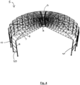
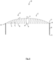
- Trusses 6 are constructed in accordance with a preferred embodiment of the second aspect of the invention. Each truss 6 comprises a compression member 7, a tension member 8, and a plurality of intermediate members 9 joining the two.
- Connecting members 10 are additionally provided laterally between adjacent trusses 6.
- each compression member 7 is connected to a compression ring 12, wherein the compression ring 12 is positioned at the top and centre of the dome 5. Additionally, a first end 13 of each tension member 8 is connected to a tension ring 14 positioned directly beneath the compression ring 13. Each tension member 8 is arranged horizontally in the embodiment shown.
- each compression member 7 and a second, outer end 16 of each tension member 8 is connected to an upper end 17 of a column 18 such that the diaphragm of the dome 5 is raised above the ground to which a lower end 19 of each column 18 is connected.
- Columns 18 are evenly spaced around the outer, circular periphery of the dome 5. Again, cladding (not shown) is arranged over the trusses 6.
- bracing members 20 which are each arranged diagonally between adjacent columns 18. These columns 18 are known as "braced columns”.
- This process of load distribution additionally induces axial forces in the intermediate members 9, which under typical working load experience less than 5% of the axial forces in the compression and tension members, therein further helping the dome 5 cope with the non-uniform loads (wind) applied to the dome 5.
- a long span truss dome 5 is constructed as outlined below.
- Each truss 6 comprises a compression member 7, a tension member 8, and a plurality of intermediate members 9.
- the compression member 7 of each truss 6 is designed such that it is curved in a manner that will minimise bending moments experienced by each point thereon once installed.
- a support structure is then installed at the site at which the dome 5 is to be constructed. Then, a compression ring 12 is centrally positioned, using the support structure, such that it is positioned directly above the intended centre of the diaphragm of the dome and is positioned at a height corresponding to the intended height of the dome. A tension ring 14 is then positioned, also using the support structure, such that it is directly beneath the compression ring 12.
- a first column 18 is then installed such that a lower end 19 thereof is fixed to the ground and an upper end 17 thereof is positioned above, generally, directly above, the lower end 19.
- a crane is used to lift a first one of the trusses 6.
- a first, inner end 11 of the compression member 7 of the first truss 6 is then connected to the compression ring 12, and a first, inner end 13 of the tension member 8 is connected to the tension ring 14.
- a second, outer end 15 of the compression member 7 and a second, outer end 16 of the tension member 8 are subsequently connected to the upper end 17 of the column 18. They may be connected to the same point thereon.
- the crane is then disconnected from the first truss 6.
- a second column 18 is then installed on the opposite side of the dome 5 to the first column in a similar manner to the first column.
- a second one of the trusses 6 is then lifted using the crane and connected to the compression ring 12, the tension ring 14, and the second column 18 in much the same manner as the first truss 6 was installed.
- the crane is then disconnected from the second truss 6.
- Further trusses may then be installed in a similar manner to the first and second trusses.
- the support structure can be removed, leaving the compression ring 12 and the tension ring 14 supported by no structures other than the eight trusses. At this point, the trusses undergo deflection from a supported position to a final position.
- y 24 D L 2 a + 3 u ⁇ a 3 L x 3 ⁇ a + u 2 x 2 + aL 4 + uL 2 x
- y denotes the height 21 of a particular point 22 on the compression member 7 above the diaphragm of the dome (m)
- a denotes the uniformly distributed load due to cladding, any support structures present, and loads imposed at the eaves (kN/m)
- u denotes the uniformly distributed load due to the self-weight of the truss 6 (kN/m)
- L denotes the span of the dome (m)
- D denotes the height of the dome (m)
- x denotes the minimum horizontal distance 23 of the particular point 22 from the eaves of the dome (m).
- Cladding is then optionally arranged over all or part of the top of these trusses 6.
- Other stadia etc. components may also be installed, including lights, electrical systems etc.
- the dome is thus conveniently erected using reduced support structure than hitherto needed.
Landscapes
- Engineering & Computer Science (AREA)
- Architecture (AREA)
- Physics & Mathematics (AREA)
- Electromagnetism (AREA)
- Civil Engineering (AREA)
- Structural Engineering (AREA)
- Tents Or Canopies (AREA)
Priority Applications (1)
| Application Number | Priority Date | Filing Date | Title |
|---|---|---|---|
| EP22166156.4A EP4253680A1 (fr) | 2022-03-31 | 2022-03-31 | Dômes à longue portée et construction associée |
Applications Claiming Priority (1)
| Application Number | Priority Date | Filing Date | Title |
|---|---|---|---|
| EP22166156.4A EP4253680A1 (fr) | 2022-03-31 | 2022-03-31 | Dômes à longue portée et construction associée |
Publications (1)
| Publication Number | Publication Date |
|---|---|
| EP4253680A1 true EP4253680A1 (fr) | 2023-10-04 |
Family
ID=81386787
Family Applications (1)
| Application Number | Title | Priority Date | Filing Date |
|---|---|---|---|
| EP22166156.4A Pending EP4253680A1 (fr) | 2022-03-31 | 2022-03-31 | Dômes à longue portée et construction associée |
Country Status (1)
| Country | Link |
|---|---|
| EP (1) | EP4253680A1 (fr) |
Cited By (3)
| Publication number | Priority date | Publication date | Assignee | Title |
|---|---|---|---|---|
| CN113775096A (zh) * | 2021-08-31 | 2021-12-10 | 深圳市建筑设计研究总院有限公司 | 刚性屋盖、建筑及刚性屋盖的施工方法 |
| JP2023023583A (ja) * | 2021-08-05 | 2023-02-16 | 株式会社竹中工務店 | ドーム構造 |
| CN117905169A (zh) * | 2024-03-05 | 2024-04-19 | 北京市建筑工程装饰集团有限公司 | 一种基于bim的大跨度空间曲面钢结构及施工方法 |
Citations (6)
| Publication number | Priority date | Publication date | Assignee | Title |
|---|---|---|---|---|
| CH426201A (fr) * | 1965-04-27 | 1966-12-15 | Vevey Atel Const Mec | Réservoir |
| US5067288A (en) * | 1989-05-16 | 1991-11-26 | Shimizu Construction Co., Ltd. | Dome structure |
| JPH07197582A (ja) * | 1993-12-29 | 1995-08-01 | Mamoru Kawaguchi | ドーム式屋根架構のケーブル張力導入方法 |
| JPH09256535A (ja) * | 1996-03-19 | 1997-09-30 | Tomoe Corp | ドーム型屋根の構築方法 |
| WO2001002657A1 (fr) * | 1999-07-06 | 2001-01-11 | Andrew David Tomlinson | Structure |
| CN110258802A (zh) * | 2019-05-31 | 2019-09-20 | 东南大学 | 一种基于飞燕式桁架拱的超大跨径轮辐式弦支穹顶结构 |
-
2022
- 2022-03-31 EP EP22166156.4A patent/EP4253680A1/fr active Pending
Patent Citations (6)
| Publication number | Priority date | Publication date | Assignee | Title |
|---|---|---|---|---|
| CH426201A (fr) * | 1965-04-27 | 1966-12-15 | Vevey Atel Const Mec | Réservoir |
| US5067288A (en) * | 1989-05-16 | 1991-11-26 | Shimizu Construction Co., Ltd. | Dome structure |
| JPH07197582A (ja) * | 1993-12-29 | 1995-08-01 | Mamoru Kawaguchi | ドーム式屋根架構のケーブル張力導入方法 |
| JPH09256535A (ja) * | 1996-03-19 | 1997-09-30 | Tomoe Corp | ドーム型屋根の構築方法 |
| WO2001002657A1 (fr) * | 1999-07-06 | 2001-01-11 | Andrew David Tomlinson | Structure |
| CN110258802A (zh) * | 2019-05-31 | 2019-09-20 | 东南大学 | 一种基于飞燕式桁架拱的超大跨径轮辐式弦支穹顶结构 |
Cited By (4)
| Publication number | Priority date | Publication date | Assignee | Title |
|---|---|---|---|---|
| JP2023023583A (ja) * | 2021-08-05 | 2023-02-16 | 株式会社竹中工務店 | ドーム構造 |
| CN113775096A (zh) * | 2021-08-31 | 2021-12-10 | 深圳市建筑设计研究总院有限公司 | 刚性屋盖、建筑及刚性屋盖的施工方法 |
| CN113775096B (zh) * | 2021-08-31 | 2025-04-08 | 深圳市建筑设计研究总院有限公司 | 刚性屋盖、建筑及刚性屋盖的施工方法 |
| CN117905169A (zh) * | 2024-03-05 | 2024-04-19 | 北京市建筑工程装饰集团有限公司 | 一种基于bim的大跨度空间曲面钢结构及施工方法 |
Similar Documents
| Publication | Publication Date | Title |
|---|---|---|
| US6345638B1 (en) | Multiple peak cable tent | |
| EP0237667B1 (fr) | Ferme de bâtiment | |
| CN112267709A (zh) | 一种大跨度张弦梁结构的分段拆除施工方法 | |
| US4676045A (en) | Post-tensioned steel structure | |
| CN102418381A (zh) | 钢梁与先张法预应力叠合梁相结合的房屋结构体系及其施工方法 | |
| EP0161878B1 (fr) | Structure de toit | |
| US6343445B1 (en) | Tower structure | |
| CN116290905B (zh) | 屋面钢结构改建方法 | |
| CN213418186U (zh) | 一种圆形屋面钢桁架结构 | |
| KR100760435B1 (ko) | 신축조절 가능한 가설 지주 | |
| KR20020080931A (ko) | 평면 격자형 케이블구조를 이용한 구조물 건설공법 | |
| EP1055042B1 (fr) | Tente sur cables a plusieurs sommets | |
| JP4691431B2 (ja) | 屋根構造体およびその構築方法 | |
| JP3215059B2 (ja) | 塔状構造物屋根の構築工法 | |
| US4276733A (en) | Method of constructing and erecting a dome-shaped structure | |
| US4074502A (en) | Method for manufacturing a support framework | |
| CN211772899U (zh) | 用于双飞翼拱桥主副拱施工的临时支架 | |
| JP3409265B2 (ja) | 膜構造大型ドームとその構築方法 | |
| CN210289133U (zh) | 斜柱模板支撑体系 | |
| CN116856544B (zh) | 一种环向倾斜桁架结构及其安装方法 | |
| CN212270687U (zh) | 一种用于倾斜式主副拱交叉段的钢管支架临时墩 | |
| GB2074211A (en) | Suspended roof | |
| JP2946074B2 (ja) | 大屋根架設方法 | |
| CN117536335A (zh) | 一种基于bim的星空花园钢结构铰接安装方法 | |
| KR20230152389A (ko) | 경사말뚝을 이용한 흙막이 구조물 |
Legal Events
| Date | Code | Title | Description |
|---|---|---|---|
| PUAI | Public reference made under article 153(3) epc to a published international application that has entered the european phase |
Free format text: ORIGINAL CODE: 0009012 |
|
| STAA | Information on the status of an ep patent application or granted ep patent |
Free format text: STATUS: THE APPLICATION HAS BEEN PUBLISHED |
|
| AK | Designated contracting states |
Kind code of ref document: A1 Designated state(s): AL AT BE BG CH CY CZ DE DK EE ES FI FR GB GR HR HU IE IS IT LI LT LU LV MC MK MT NL NO PL PT RO RS SE SI SK SM TR |