EP4253773A1 - Befestigungsklammer - Google Patents
Befestigungsklammer Download PDFInfo
- Publication number
- EP4253773A1 EP4253773A1 EP23164846.0A EP23164846A EP4253773A1 EP 4253773 A1 EP4253773 A1 EP 4253773A1 EP 23164846 A EP23164846 A EP 23164846A EP 4253773 A1 EP4253773 A1 EP 4253773A1
- Authority
- EP
- European Patent Office
- Prior art keywords
- fastening clamp
- substrate
- retaining legs
- component
- mounting hole
- Prior art date
- Legal status (The legal status is an assumption and is not a legal conclusion. Google has not performed a legal analysis and makes no representation as to the accuracy of the status listed.)
- Granted
Links
Images




Classifications
-
- F—MECHANICAL ENGINEERING; LIGHTING; HEATING; WEAPONS; BLASTING
- F16—ENGINEERING ELEMENTS AND UNITS; GENERAL MEASURES FOR PRODUCING AND MAINTAINING EFFECTIVE FUNCTIONING OF MACHINES OR INSTALLATIONS; THERMAL INSULATION IN GENERAL
- F16B—DEVICES FOR FASTENING OR SECURING CONSTRUCTIONAL ELEMENTS OR MACHINE PARTS TOGETHER, e.g. NAILS, BOLTS, CIRCLIPS, CLAMPS, CLIPS OR WEDGES; JOINTS OR JOINTING
- F16B2/00—Friction-grip releasable fastenings
- F16B2/20—Clips, i.e. with gripping action effected solely by the inherent resistance to deformation of the material of the fastening
- F16B2/22—Clips, i.e. with gripping action effected solely by the inherent resistance to deformation of the material of the fastening of resilient material, e.g. rubbery material
- F16B2/24—Clips, i.e. with gripping action effected solely by the inherent resistance to deformation of the material of the fastening of resilient material, e.g. rubbery material of metal
-
- F—MECHANICAL ENGINEERING; LIGHTING; HEATING; WEAPONS; BLASTING
- F16—ENGINEERING ELEMENTS AND UNITS; GENERAL MEASURES FOR PRODUCING AND MAINTAINING EFFECTIVE FUNCTIONING OF MACHINES OR INSTALLATIONS; THERMAL INSULATION IN GENERAL
- F16B—DEVICES FOR FASTENING OR SECURING CONSTRUCTIONAL ELEMENTS OR MACHINE PARTS TOGETHER, e.g. NAILS, BOLTS, CIRCLIPS, CLAMPS, CLIPS OR WEDGES; JOINTS OR JOINTING
- F16B21/00—Means for preventing relative axial movement of a pin, spigot, shaft or the like and a member surrounding it; Stud-and-socket releasable fastenings
- F16B21/10—Means for preventing relative axial movement of a pin, spigot, shaft or the like and a member surrounding it; Stud-and-socket releasable fastenings by separate parts
- F16B21/20—Means for preventing relative axial movement of a pin, spigot, shaft or the like and a member surrounding it; Stud-and-socket releasable fastenings by separate parts for bolts or shafts without holes, grooves, or notches for locking members
- F16B21/205—Means for preventing relative axial movement of a pin, spigot, shaft or the like and a member surrounding it; Stud-and-socket releasable fastenings by separate parts for bolts or shafts without holes, grooves, or notches for locking members the connecting means having gripping edges in the form of a helix
-
- F—MECHANICAL ENGINEERING; LIGHTING; HEATING; WEAPONS; BLASTING
- F16—ENGINEERING ELEMENTS AND UNITS; GENERAL MEASURES FOR PRODUCING AND MAINTAINING EFFECTIVE FUNCTIONING OF MACHINES OR INSTALLATIONS; THERMAL INSULATION IN GENERAL
- F16B—DEVICES FOR FASTENING OR SECURING CONSTRUCTIONAL ELEMENTS OR MACHINE PARTS TOGETHER, e.g. NAILS, BOLTS, CIRCLIPS, CLAMPS, CLIPS OR WEDGES; JOINTS OR JOINTING
- F16B21/00—Means for preventing relative axial movement of a pin, spigot, shaft or the like and a member surrounding it; Stud-and-socket releasable fastenings
- F16B21/10—Means for preventing relative axial movement of a pin, spigot, shaft or the like and a member surrounding it; Stud-and-socket releasable fastenings by separate parts
- F16B21/20—Means for preventing relative axial movement of a pin, spigot, shaft or the like and a member surrounding it; Stud-and-socket releasable fastenings by separate parts for bolts or shafts without holes, grooves, or notches for locking members
-
- F—MECHANICAL ENGINEERING; LIGHTING; HEATING; WEAPONS; BLASTING
- F16—ENGINEERING ELEMENTS AND UNITS; GENERAL MEASURES FOR PRODUCING AND MAINTAINING EFFECTIVE FUNCTIONING OF MACHINES OR INSTALLATIONS; THERMAL INSULATION IN GENERAL
- F16B—DEVICES FOR FASTENING OR SECURING CONSTRUCTIONAL ELEMENTS OR MACHINE PARTS TOGETHER, e.g. NAILS, BOLTS, CIRCLIPS, CLAMPS, CLIPS OR WEDGES; JOINTS OR JOINTING
- F16B21/00—Means for preventing relative axial movement of a pin, spigot, shaft or the like and a member surrounding it; Stud-and-socket releasable fastenings
- F16B21/06—Releasable fastening devices with snap-action
- F16B21/07—Releasable fastening devices with snap-action in which the socket has a resilient part
- F16B21/073—Releasable fastening devices with snap-action in which the socket has a resilient part the socket having a resilient part on its inside
-
- F—MECHANICAL ENGINEERING; LIGHTING; HEATING; WEAPONS; BLASTING
- F16—ENGINEERING ELEMENTS AND UNITS; GENERAL MEASURES FOR PRODUCING AND MAINTAINING EFFECTIVE FUNCTIONING OF MACHINES OR INSTALLATIONS; THERMAL INSULATION IN GENERAL
- F16B—DEVICES FOR FASTENING OR SECURING CONSTRUCTIONAL ELEMENTS OR MACHINE PARTS TOGETHER, e.g. NAILS, BOLTS, CIRCLIPS, CLAMPS, CLIPS OR WEDGES; JOINTS OR JOINTING
- F16B5/00—Joining sheets or plates, e.g. panels, to one another or to strips or bars parallel to them
- F16B5/12—Fastening strips or bars to sheets or plates, e.g. rubber strips, decorative strips for motor vehicles, by means of clips
Definitions
- the present application relates to a fastener, particularly in the automotive field, for connecting two components.
- Fasteners can connect multiple components together, such as interior parts, frames, and panels of a vehicle.
- a first component is first connected to a fastener when connected, and then the fastener connected to the first component is mounted at a corresponding position of a second component; or the fastener is first mounted at a corresponding position of the second component, and then the fastener is connected to the first component, so that the first component and the second component are connected to each other.
- a vehicle wire clamp needs to be connected to a body sheet metal by a using fastener such that an interior panel is securely connected to the body sheet metal.
- the present application provides a fastening clamp, used for connecting a first component to a second component having a connecting post, including: a substrate on which a mounting hole is provided; at least two first retaining legs, and at least two second retaining legs, where the mounting hole is used to receive the connecting post of the second component, proximal ends of the at least two first retaining legs are connected to an edge of the mounting hole and extend obliquely from one side of the substrate towards one another in a direction away from the substrate, the at least two first retaining legs are resilient and configured to deflect about the proximal ends of the at least two first retaining legs, proximal ends of the at least two second retaining legs are connected to the edge of the mounting hole and extend obliquely from one side of the substrate towards one another in a direction away from the substrate, and the at least two first retaining legs and the at least two second retaining legs are on the same side of the substrate; where distal ends of the at least two second retaining legs are closer to the substrate than distal ends of
- the at least two second retaining legs are staggered with the at least two first retaining legs about the mounting hole.
- the at least two second retaining legs and the at least two first retaining legs are arranged along a circumferential direction, the fastening clamp being clampable on the cylindrical connecting post of the second component and rotating relative to the connecting post of the second component, the at least two second retaining legs being in contact with a sidewall of the connecting post of the second component.
- each of the at least two first retaining legs and each of the at least two second retaining legs have a first contact and a second contact, respectively, the first contact being capable of contacting the second contact and the connecting post of the second component, and the first contact and the second contact extending helically around a centerline of the mounting hole.
- a distance between the first contact and the centerline of the mounting hole is greater than a distance between the second contact and the centerline of the mounting hole.
- the substrate has a first side and a second side, the at least two second retaining legs and the at least two first retaining legs extend outwardly from the first side, and the second side of the substrate has an anti-release structure.
- the substrate has a front side and a back side
- the fastener is inserted into a mounting component in a direction from the front side to the back side
- the anti-release structure is a convex portion protruding from a surface of the second side
- the convex portion tapers and gradually becomes thicker in the direction from the front side to the back side.
- the fastening clamp is integrally made of a metallic material.
- hardness of the first contact and the second contact is greater than hardness of the connecting post of the second component.
- a front side of the substrate has a front side flap bent inwardly from an edge of the front side, and the front side flap extends in the same direction as the substrate.
- the back side of the substrate has a back side flap extending from an edge of the back side in a direction away from the first side of the substrate to form a stop portion.
- the substrate has a stiffener protruding from a surface of the first side of the substrate, the stiffener is proximate to the back side of the substrate, and the stiffener is an arc curved toward a centerline of the mounting hole of the substrate.
- the present application also provides a fastening clamp assembly, including: the fastening clamp described above and a connection seat; where the connection seat has a pair of receiving slots and a bottom, both sides of the substrate being able to enter the pair of receiving slots respectively to restrict movement of the fastening clamp in a direction perpendicular to the substrate; the bottom having an opening that aligns with the mounting hole when the fastening clamp is mounted in the connection seat.
- connection seat has a pair of sides extending from both sides of the bottom, the pair of sides are disposed oppositely, and each of the pair of sides includes a sidewall and a convex edge, where the sidewall is connected to the bottom, the convex edge extends from the sidewall towards the other side of the pair of sides, and the side and the convex edge enclose to form a receiving slot in a pair of receiving slots.
- connection seat is removably connected or integrally formed with the first component.
- the fastening clamp in the present application can be connected to a cylindrical part of a vehicle.
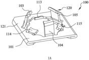
- FIG. 1A is a perspective view of a first example of a fastening clamp in the present application
- FIG. 1B is a perspective view of the fastening clamp of FIG. 1A at a second angle
- FIG. 1C is a top view of the fastening clamp of FIG. 1A
- FIG. 1D is a side view of the fastening clamp of FIG. 1A
- FIGS. 1A-1D show a structure of the fastening clamp.
- a fastening clamp 100 is used to connect a first component to a second component having a connecting post.
- the fastening clamp 100 includes a substrate 101 and a clamping portion 120.
- the substrate 101 is generally flat and has a first side 121 and a second side 122.
- the substrate 101 has a mounting hole 108 running through the first side 121 and the second side 122 of the substrate 101.
- the mounting hole 108 has a centerline C that extends through the center of the mounting hole 108 and perpendicular to the plane in which the mounting hole 108 is located.
- the clamping portion 120 extends from the first side 121 in a direction away from the substrate 101.
- the clamping portion 120 includes three first retaining legs 103, 104, and 105, and three second retaining legs 113, 114, and 115.
- the three first retaining legs 103, 104, and 105 and the three second retaining legs 113, 114, and 115 are staggered along a circumferential direction.
- the height of the three first retaining legs 103, 104, and 105 is greater than the height of the three second retaining legs 113, 114, and 115, so that the top of the three first retaining legs 103, 104, and 105 is higher than the height of the three second retaining legs 113, 114, and 115.
- the three first retaining legs 103, 104, and 105 and the three second retaining legs 113, 114, and 115 are all resilient to some extent and deflectable relative to the substrate 101.
- the three first retaining legs 103, 104, and 105 and the three second retaining legs 113, 114, and 115 are provided with a thinned or narrowed design at a connection to the substrate to adjust elasticity of the three first retaining legs 103, 104, and 105 and the three second retaining legs 113, 114, and 115 to a suitable range.
- Each of the three first retaining legs 103, 104, and 105 includes a body portion 131 and an extension portion 132, where the body portion 131 is located between the substrate 101 and the extension portion 132, and the body portion 131 is inclined at a greater angle with respect to the substrate 101 than the extension portion 132.
- Each of the first retaining legs 103, 104, and 105 generally presents a shape that curves toward the centerline C of the mounting hole 108.
- the distal end of the extension portion 132 forms a contact 135 capable of contacting the connecting post of the second component.
- the contact 135 is arranged along the direction of a helix line, i.e., extends helically around the centerline of mounting hole 108.
- Each contact 135 of the three first retaining legs 103, 104 and 105 is arranged around the cylindrical connecting post of the second component.
- the height of the contact 135 is different on both sides in the circumferential direction, where the height on a first side is greater than the height on a second side.
- the first side of each contact 135 is located between second sides of two adjacent contacts 135. That is, in the direction of rotation along the circumference, the first side of each contact 135 is located upstream or downstream of the second side.
- the three second retaining legs 113, 114, and 115 extend from the substrate 101 towards the centerline C of the mounting hole.
- the distal end of each second retaining leg also has a contact 136, and similar to the contact 135, the contact 136 is capable of contacting the connecting post of the second component.
- the contact 136 is arranged along the direction of a helix line, i.e., extends helically around the centerline C of mounting hole 108.
- Each contact 136 of the three first retaining legs 113, 114 and 115 is arranged around the cylindrical connecting post of the second component.
- the height of the contact 136 is different on both sides in the circumferential direction, where the height on a first side is greater than the height on a second side.
- each contact 135 is located between second sides of two adjacent contacts 136. That is, in the direction of rotation along the circumference, the first side of each contact 136 is located upstream or downstream of the second side.
- the contacts arranged along the direction of the helix line facilitate removal of the fastening clamp from the second component.
- the distance from the contact 136 to the centerline C is equal to the distance from the contact 135 to the centerline C.
- the contact 136 is farther from the centerline C than the contact 135 is from the centerline C.
- the first retaining legs 103, 104, and 105 and the second retaining legs 113, 114, and 115 are all deformed after being mounted in place, and the contact 135 and the contact 136 are clamped with the connecting post of the second component at different heights of the connecting post of the second component, which can further strengthen the pulling force between the fastening clamp and the connecting post of the second component.
- the first retaining legs 103, 104 and 105 are deformed after being mounted in place, the contact 135 is clamped with the connecting post of the second component, a small amount of deformity or no deformation occurs at the contact 136, and the contact 136 has a small amount of clearance abutting on the connecting post of the second component or with the connecting post of the second component.
- the second retaining legs 113, 114, and 115 are used to prevent the fastening clamp from tilting relative to the connecting post of the second component.
- the substrate 101 has a front side 161 and a back side 162, and a pair of convex portions 156 and 157 protruding from a second side 122 of the substrate 101.
- the convex portions 156 and 157 form an anti-release structure to prevent the fastening clamp from falling off of the second component.
- the convex portions 156 and 157 are generally triangular, and the convex portions 156 and 157 taper and gradually become thicker in a direction from the front side 161 to the back side 162. The convex portions 156 and 157 thus form a barb.
- the convex portions 156 and 157 have tips 158 and 159 proximate the back side 162, and the tips 158 and 159 are capable of at least partially clamping into the connecting post of the second component to prevent the fastening clamp from falling off of the connecting post of the second component.
- the fastening clamp is an integral member made through metal sheet stamping, and has a certain hardness.
- the substrate 101 has double layers and is formed by bending a metal sheet, thereby strengthening the strength of the substrate 101.
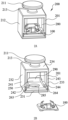
- FIG. 2A is a perspective view of a first example of a fastening clamp assembly in the present application
- FIG. 2B is an exploded view of the fastening clamp assembly of FIG. 2A
- FIG. 2C is a cross-sectional view of the fastening clamp assembly in the present application.
- the fastening clamp assembly 200 includes a connection seat 201 and a fastening clamp 100, the fastening clamp 100 is mounted in the connection seat 201, and the connection seat 201 is used for connecting to the first component.
- the connection seat 201 includes a head 211, a neck 213, and a body 212, both of the head 211 and the neck 213 are cylindrical, and the diameter of the head 211 is larger than the diameter of the neck 213.
- the body 212 is generally a cube, and the body 212 includes a bottom 231, a pair of sides 232 and 233, and a top 234.
- the top 234 is connected to the head 211, and the top 234 is larger in size than the neck 213.
- the sides 232 and 233 extend from both sides of the bottom 231 and connect to the top 234.
- the sides 232 and 233, the bottom 231, and the top 234 enclose to form a cavity 250, and the fastening clamp is able to enter the cavity 250.
- the bottom 231 has an opening 285 in communication with the cavity 250.
- the side 232 includes a sidewall 241 and a convex edge 242 extending from an inner side of the sidewall 241 toward the side 233.
- the side 233 includes a sidewall 243 and a convex edge 244 extending from an inner side of the sidewall 243 toward the side 232.
- a receiving slot 263 is formed among the convex edge 242, the bottom 231, and the sidewall 241, and a receiving slot 264 is formed among the convex edge 24, the bottom 231, and the sidewall 243.
- the body 212 also includes a front end and a back end, the front end has an opening 280, and the back end has a stop portion 290.
- the stop portion 290 and the bottom 231 extend towards the top 234.
- the stop portion 290 is flush with the top of the convex edges 242 and 244.
- the substrate 101 is capable of being inserted into the receiving slots 263 and 264 in a direction from the front side 161 to the back side 162.
- the receiving slots 263 and 264 can restrict movement of the fastening clamp 100 in the vertical direction.
- the convex portions 156 and 157 of the fastening clamp 100 can be clamped with the bottom 231 of the connection seat 201 to limit the fastening clamp 100 from sliding out of the connection seat in the direction from the back side 162 to the front side 161.
- the stop portion 290 can restrict the fastening clamp 100 from sliding out of the connection seat in the direction from the front side 161 to the back side 162.
- connection seat 201 is made of a plastic material having a hardness less than that of the fastening clamp 100.
- FIG. 3A is an exploded view of the fastening clamp assembly and the second component and the first component of the first example of FIG. 2A
- FIG. 3B is a perspective view of the fastening clamp assembly after being connected to the second component and the first component
- FIG. 3C is a cross-sectional view of the fastening clamp assembly after being connected to the second component and the first component of FIG. 2A .
- a fastening clamp assembly 200 is capable of connecting a second component 301 to a first component 302.
- the second component 301 is a sheet metal of a vehicle body
- the sheet metal has a sheet metal body and a cylinder 311 raised on the surface of the sheet metal body
- the first component is a pipe clamp for supporting a pipeline in a vehicle.
- the first component has a pipe clamp connection portion 360 into which the fastening clamp assembly 200 can be loaded.
- the pipe clamp connection portion 360 includes a lower plate 361 having an opening 371 and an upper plate 362 having a slot 372.
- the neck 213 of the connection seat 201 is able to enter the slot 372, and the head 211 and the top of the body 212 are located on both sides of the upper plate 362, respectively, so that the fastening clamp assembly 200 cannot move in the vertical direction relative to the first component.
- the shape of the pipe clamp connection portion 360 matches the shape of the connection seat 201, so that the connection seat 201 cannot rotate relative to the first component 302.
- the first operation first inserts the fastening clamp assembly 200 onto a cylindrical connecting post 311 of the second component 301 such that the cylindrical connecting post 311 passes through the opening 285 of the connection seat 201 and through the mounting hole 108 of the fastening clamp 100 in turn.
- the top of the cylindrical connecting post 311 exceeds the distal ends of the three first retaining legs 103, 104, and 105, and the fastening clamp assembly 200 is clamped on the cylindrical connecting post 311 via the elasticity of the first retaining legs 103, 104, and 105 and the second retaining legs 113, 114, and 115.
- the first component 302 is then sleeved on the fastening clamp assembly 200 so that the first component 302 is connected to the connecting post 311 of the second component.
- the second operation first mounts the fastening clamp assembly 200 into the pipe clamp connection portion 360 of the first component 302, and then inserts the first component 302 and the fastening clamp assembly 200 together onto the cylindrical connecting post 311 of the second component 301.
- the fastening clamp 100 when the fastening clamp 100 is connected to the cylindrical connecting post 311 of the second component 301, the first retaining legs 103, 104, and 105 and the second retaining legs 113, 114, and 115 are deflected and clamped against the sidewall of the cylindrical connecting post 311.
- the material hardness of the cylindrical connecting post 311 is lower than the material hardness of the contact of the first retaining legs and the second retaining legs, so that the contact can be partially inserted into the cylindrical connecting post 311 and the fastening clamp is stably clamped on the cylindrical connecting post 311.
- the fastening clamp 100 when the fastening clamp 100 is connected to the cylindrical connecting post 311 of the second component 301, the first retaining legs 103, 104 and 105 are deflected, clamped on the sidewall of the cylindrical connecting post 311, and the second retaining legs 113, 114 and 115 abut against or have a small gap with the cylindrical connecting post 311. That is, the second retaining legs 113, 114, and 115 can prevent the fastening clamp 100 from tilting relative to the cylindrical connecting post 311 of the second component 301; the first retaining legs 103, 104, and 105 clamp the cylindrical connecting post of the second component 301, preventing the fastening clamp 100 from disengaging from the cylindrical connecting post 311 of the second component 301.
- FIG. 4A is an exploded view of a fastening clamp assembly of a second example of the present application and FIG. 4B is a perspective view of the fastening clamp assembly of the second example of FIG. 4A after being connected to a first component.
- the fastening clamp assembly includes a fastening clamp 100 and a first component 402.
- the first component 402 is a pipe clamp.
- the fastening clamp 100 may be mounted directly on the first component 402 without the need of providing the connection seat 201.
- the first component 402 is provided with receiving slots 463 and 464, and the fastening clamp 100 is able to enter the receiving slots 463 and 464 and is not easily disengaged from the first component.
- the first component 402 and the fastening clamp 100 can be connected together to the second component having a cylindrical connecting post.
- connection seat on the first component 402 without the need for separate arrangement of the connection seat.
- FIG. 5A is a perspective view of a second example of a fastening clamp in the present application
- FIG. 5B is a perspective view of the fastening clamp of FIG. 5A at another angle.
- the structure of a substrate 501 of a fastening clamp 500 is different.
- the fastening clamp 500 includes the substrate 501 and a clamping portion 520.
- the substrate 501 is generally flat and has a first side 521 and a second side 522.
- the clamping portion 520 extends outwardly from the first side 521 of the substrate 501.
- the substrate 501 also has a front side 561 and a back side 562, and a front side flap 581 and a back side flap 582.
- the back side flap 582 extends from the edge of the back side 562 in a direction away from the first side 521 of the substrate 501, to form a stop portion 577. That is, the extension direction of the back side flap 582 is substantially perpendicular to the extension direction of the substrate 501.
- the back side flap 582 and the clamping portion 520 are located on both sides of the substrate 501, respectively.
- the front side flap 581 is bent from the edge of the front side 161 towards the second side 522 of the substrate 501, and the extension direction of the front side flap 581 is the same as the extension direction of the substrate 501. In one example of the present application, the front side flap 581 fits the surface of the second side 522 of the substrate 501.
- the substrate 501 also has a stiffener 556 protruding from the surface of the first side 521 of the substrate 501, the stiffener 556 is proximate to the back side 562 of the substrate 501, and the stiffener 556 is an arc curved toward the centerline of the mounting hole 508 of the substrate 501.
- the stiffener 556, the front side flap 581, and the back side flap 582 all increase the strength of the fastening clamp 500 and prevent deformation of the fastening clamp 500.
- FIG. 6A is a perspective view of a third example of a fastening clamp assembly in the present application
- FIG. 6B is an exploded view of the fastening clamp assembly of FIG. 6A .
- the fastening assembly includes a fastening clamp 500 and a first component 602.
- the first component 602 is a pipe clamp.
- the first component 602 has a pipe clamp connection portion 660.
- the pipe clamp connection portion 660 includes a pair of sidewalls 641 and 644, a bottom 643, and a pair of convex edges 646 and 647.
- the pair of sidewalls 641 are connected to both sides of the bottom 643 and extend generally perpendicular to the bottom 643.
- the pair of convex edges 646 and 647 extend from the inner side of the sidewalls 641 and 644 toward each other, respectively.
- the pair of sidewalls 641 and 644, the bottom 643, and the pair of convex edges 646 and 647 enclose to form a pair of receiving slots 663 and 664, and both sides of the substrate 501 of the fastening clamp 500 are able to enter into the receiving slots 663 and 664.
- the bottom 663 has a recess 677 whose shape mates with the shape of a stop portion 577 of the fastening clamp 500. When the fastening clamp 500 is mounted in place in the first component 602, the stop portion 577 enters the recess 677. The stop portion 577 can restrict movement of the fastening clamp 500 relative to the first component 602 in the insertion direction of the fastening clamp 500.
- the fastening clamps 100 and 500 in the present application can be mounted on a cylindrical connecting post with a smooth outer wall. No threads or convex portions are required on the cylindrical connecting post.
- the cylindrical connecting post may be integrally casted with the vehicle body, and they no longer need to be connected by welding or other joining processes.
Landscapes
- Engineering & Computer Science (AREA)
- General Engineering & Computer Science (AREA)
- Mechanical Engineering (AREA)
- Insertion Pins And Rivets (AREA)
- Connection Of Plates (AREA)
Priority Applications (1)
| Application Number | Priority Date | Filing Date | Title |
|---|---|---|---|
| EP25183047.7A EP4592540A3 (de) | 2022-03-31 | 2023-03-28 | Befestigungsklammer |
Applications Claiming Priority (2)
| Application Number | Priority Date | Filing Date | Title |
|---|---|---|---|
| CN202210337112 | 2022-03-31 | ||
| CN202310270987.8A CN116892551A (zh) | 2022-03-31 | 2023-03-16 | 紧固夹 |
Related Child Applications (1)
| Application Number | Title | Priority Date | Filing Date |
|---|---|---|---|
| EP25183047.7A Division EP4592540A3 (de) | 2022-03-31 | 2023-03-28 | Befestigungsklammer |
Publications (2)
| Publication Number | Publication Date |
|---|---|
| EP4253773A1 true EP4253773A1 (de) | 2023-10-04 |
| EP4253773B1 EP4253773B1 (de) | 2025-06-25 |
Family
ID=85778812
Family Applications (2)
| Application Number | Title | Priority Date | Filing Date |
|---|---|---|---|
| EP25183047.7A Pending EP4592540A3 (de) | 2022-03-31 | 2023-03-28 | Befestigungsklammer |
| EP23164846.0A Active EP4253773B1 (de) | 2022-03-31 | 2023-03-28 | Befestigungsklammer |
Family Applications Before (1)
| Application Number | Title | Priority Date | Filing Date |
|---|---|---|---|
| EP25183047.7A Pending EP4592540A3 (de) | 2022-03-31 | 2023-03-28 | Befestigungsklammer |
Country Status (2)
| Country | Link |
|---|---|
| US (1) | US12221992B2 (de) |
| EP (2) | EP4592540A3 (de) |
Cited By (3)
| Publication number | Priority date | Publication date | Assignee | Title |
|---|---|---|---|---|
| US12221992B2 (en) | 2022-03-31 | 2025-02-11 | Illinois Tool Works Inc. | Fastening clip |
| WO2025237259A1 (en) * | 2024-05-15 | 2025-11-20 | Norma Ejt(Changzhou) Co., Ltd. | Washer, method for fastening v-clamp, and method for manufacturing washer |
| US12612981B2 (en) | 2023-03-24 | 2026-04-28 | Illinois Tool Works Inc. | Clamp assembly and pipe fixing device assembly |
Families Citing this family (1)
| Publication number | Priority date | Publication date | Assignee | Title |
|---|---|---|---|---|
| US12584505B2 (en) * | 2022-07-19 | 2026-03-24 | Vanessa Sabur | Modular storage clip |
Citations (6)
| Publication number | Priority date | Publication date | Assignee | Title |
|---|---|---|---|---|
| US2236929A (en) * | 1939-01-14 | 1941-04-01 | Tinnerman Products Inc | Fastening device |
| FR2382607A1 (fr) * | 1977-03-01 | 1978-09-29 | Bar Solo | Element de fixation et outil permettant son montage |
| US4911594A (en) * | 1989-06-21 | 1990-03-27 | Trw Inc. | Push-nut type fastener |
| US6997662B2 (en) * | 2002-08-09 | 2006-02-14 | Nissan Motor Co., Ltd. | Attachment clip and attachment structure using same |
| JP2008051332A (ja) * | 2006-07-25 | 2008-03-06 | Piolax Inc | 固定クリップ |
| US9346593B2 (en) * | 2011-11-10 | 2016-05-24 | Oldcastle Precast, Inc. | Tamper resistant closure mechanism for a utility vault |
Family Cites Families (16)
| Publication number | Priority date | Publication date | Assignee | Title |
|---|---|---|---|---|
| JPS5597514A (en) * | 1979-01-17 | 1980-07-24 | Iwata Bolt Kogyo | Driveein nut |
| DE3618486C1 (de) * | 1985-07-19 | 1987-08-06 | United Carr Gmbh Trw | Kunststoffteil zur Halterung eines Gewindebolzens |
| DE3644334A1 (de) * | 1986-12-23 | 1989-03-23 | United Carr Gmbh Trw | Halteeinrichtung in einem bauteil aus kunststoff |
| US5098242A (en) * | 1991-07-10 | 1992-03-24 | Emhart Inc. | Plastic fastener for threaded stud |
| US5195860A (en) * | 1992-07-20 | 1993-03-23 | Trw Inc. | Push-on type fastener for automatic feed and installation equipment |
| JPH1047328A (ja) * | 1996-07-29 | 1998-02-17 | Topy Fastener Kogyo Kk | プッシュナット |
| US6220806B1 (en) * | 1999-03-25 | 2001-04-24 | Avaya Technology Corp. | Twin impression push nut |
| US7059022B2 (en) * | 2001-09-03 | 2006-06-13 | Newfrey Llc | Spacer for attaching a dash silencer |
| DE10358379A1 (de) * | 2003-12-11 | 2005-07-07 | Newfrey Llc, Newark | Befestigungselement |
| JP2006308020A (ja) * | 2005-04-28 | 2006-11-09 | Piolax Inc | プッシュナット |
| DE102007055878A1 (de) * | 2007-12-19 | 2009-06-25 | Hilti Aktiengesellschaft | Abdichtelement |
| US20090187215A1 (en) * | 2007-12-19 | 2009-07-23 | Abbott Laboratories | Methods and apparatus to reduce a dimension of an implantable device in a smaller state |
| US8603116B2 (en) * | 2010-08-04 | 2013-12-10 | Abbott Cardiovascular Systems, Inc. | Closure device with long tines |
| US9149276B2 (en) * | 2011-03-21 | 2015-10-06 | Abbott Cardiovascular Systems, Inc. | Clip and deployment apparatus for tissue closure |
| US12092145B2 (en) * | 2021-02-04 | 2024-09-17 | Cooper-Standard Automotive Inc. | Push-on fastener |
| US12221992B2 (en) | 2022-03-31 | 2025-02-11 | Illinois Tool Works Inc. | Fastening clip |
-
2023
- 2023-03-24 US US18/126,213 patent/US12221992B2/en active Active
- 2023-03-28 EP EP25183047.7A patent/EP4592540A3/de active Pending
- 2023-03-28 EP EP23164846.0A patent/EP4253773B1/de active Active
Patent Citations (6)
| Publication number | Priority date | Publication date | Assignee | Title |
|---|---|---|---|---|
| US2236929A (en) * | 1939-01-14 | 1941-04-01 | Tinnerman Products Inc | Fastening device |
| FR2382607A1 (fr) * | 1977-03-01 | 1978-09-29 | Bar Solo | Element de fixation et outil permettant son montage |
| US4911594A (en) * | 1989-06-21 | 1990-03-27 | Trw Inc. | Push-nut type fastener |
| US6997662B2 (en) * | 2002-08-09 | 2006-02-14 | Nissan Motor Co., Ltd. | Attachment clip and attachment structure using same |
| JP2008051332A (ja) * | 2006-07-25 | 2008-03-06 | Piolax Inc | 固定クリップ |
| US9346593B2 (en) * | 2011-11-10 | 2016-05-24 | Oldcastle Precast, Inc. | Tamper resistant closure mechanism for a utility vault |
Cited By (3)
| Publication number | Priority date | Publication date | Assignee | Title |
|---|---|---|---|---|
| US12221992B2 (en) | 2022-03-31 | 2025-02-11 | Illinois Tool Works Inc. | Fastening clip |
| US12612981B2 (en) | 2023-03-24 | 2026-04-28 | Illinois Tool Works Inc. | Clamp assembly and pipe fixing device assembly |
| WO2025237259A1 (en) * | 2024-05-15 | 2025-11-20 | Norma Ejt(Changzhou) Co., Ltd. | Washer, method for fastening v-clamp, and method for manufacturing washer |
Also Published As
| Publication number | Publication date |
|---|---|
| EP4592540A2 (de) | 2025-07-30 |
| US12221992B2 (en) | 2025-02-11 |
| EP4253773B1 (de) | 2025-06-25 |
| EP4592540A3 (de) | 2025-10-22 |
| US20230313820A1 (en) | 2023-10-05 |
Similar Documents
| Publication | Publication Date | Title |
|---|---|---|
| EP4253773B1 (de) | Befestigungsklammer | |
| US6976292B2 (en) | Resilient clip fastener | |
| EP2496847B1 (de) | Einschubbefestigungsanordnung | |
| US11519446B2 (en) | Fastener feedback feature | |
| US7096638B2 (en) | Low insertion effort U-base retainer | |
| US7891926B2 (en) | Fastener | |
| CN102686447B (zh) | 具有横构件的座椅组件 | |
| EP1094265A1 (de) | Mit weichen Verriegelungsarmen versehene Schelle | |
| KR100437629B1 (ko) | 차량의 모듈헤드라이너용 보조손잡이 고정구 | |
| US20070209166A1 (en) | T-bolt clamp quick attach latch | |
| JP2018179051A (ja) | クリップ | |
| US20010010791A1 (en) | Nut assembly with pivotable nut | |
| US8376289B2 (en) | Offset hanger | |
| US10224530B2 (en) | Battery terminal and method of assembling it | |
| US20110225778A1 (en) | Interior trim sealing fastener | |
| US20020071737A1 (en) | Nut assembly | |
| CN116892551A (zh) | 紧固夹 | |
| JP4661724B2 (ja) | シャフトとヨークとの仮止め構造 | |
| KR20240079406A (ko) | 자동차용 모듈 클립 | |
| JP4936802B2 (ja) | クランプ | |
| US20210371019A1 (en) | Fixing for a spare wheel | |
| US11815124B2 (en) | Fastener assembly | |
| US20240318747A1 (en) | Clamp Assembly and Pipe Fixing Device Assembly | |
| CN220378653U (zh) | 紧固件和紧固件组件 | |
| US20240280131A1 (en) | Pre-Assembly Member and Pre-Assembled Nut Assembly Comprising Same |
Legal Events
| Date | Code | Title | Description |
|---|---|---|---|
| PUAI | Public reference made under article 153(3) epc to a published international application that has entered the european phase |
Free format text: ORIGINAL CODE: 0009012 |
|
| STAA | Information on the status of an ep patent application or granted ep patent |
Free format text: STATUS: THE APPLICATION HAS BEEN PUBLISHED |
|
| AK | Designated contracting states |
Kind code of ref document: A1 Designated state(s): AL AT BE BG CH CY CZ DE DK EE ES FI FR GB GR HR HU IE IS IT LI LT LU LV MC ME MK MT NL NO PL PT RO RS SE SI SK SM TR |
|
| STAA | Information on the status of an ep patent application or granted ep patent |
Free format text: STATUS: REQUEST FOR EXAMINATION WAS MADE |
|
| 17P | Request for examination filed |
Effective date: 20240326 |
|
| RBV | Designated contracting states (corrected) |
Designated state(s): AL AT BE BG CH CY CZ DE DK EE ES FI FR GB GR HR HU IE IS IT LI LT LU LV MC ME MK MT NL NO PL PT RO RS SE SI SK SM TR |
|
| GRAP | Despatch of communication of intention to grant a patent |
Free format text: ORIGINAL CODE: EPIDOSNIGR1 |
|
| STAA | Information on the status of an ep patent application or granted ep patent |
Free format text: STATUS: GRANT OF PATENT IS INTENDED |
|
| RIC1 | Information provided on ipc code assigned before grant |
Ipc: F16B 5/12 20060101ALN20250129BHEP Ipc: F16B 21/07 20060101ALN20250129BHEP Ipc: F16B 21/20 20060101AFI20250129BHEP |
|
| INTG | Intention to grant announced |
Effective date: 20250214 |
|
| P01 | Opt-out of the competence of the unified patent court (upc) registered |
Free format text: CASE NUMBER: APP_12215/2025 Effective date: 20250312 |
|
| GRAS | Grant fee paid |
Free format text: ORIGINAL CODE: EPIDOSNIGR3 |
|
| GRAA | (expected) grant |
Free format text: ORIGINAL CODE: 0009210 |
|
| STAA | Information on the status of an ep patent application or granted ep patent |
Free format text: STATUS: THE PATENT HAS BEEN GRANTED |
|
| AK | Designated contracting states |
Kind code of ref document: B1 Designated state(s): AL AT BE BG CH CY CZ DE DK EE ES FI FR GB GR HR HU IE IS IT LI LT LU LV MC ME MK MT NL NO PL PT RO RS SE SI SK SM TR |
|
| REG | Reference to a national code |
Ref country code: GB Ref legal event code: FG4D |
|
| REG | Reference to a national code |
Ref country code: CH Ref legal event code: EP |
|
| REG | Reference to a national code |
Ref country code: DE Ref legal event code: R096 Ref document number: 602023004198 Country of ref document: DE |
|
| REG | Reference to a national code |
Ref country code: CH Ref legal event code: EP |
|
| REG | Reference to a national code |
Ref country code: IE Ref legal event code: FG4D |
|
| PG25 | Lapsed in a contracting state [announced via postgrant information from national office to epo] |
Ref country code: FI Free format text: LAPSE BECAUSE OF FAILURE TO SUBMIT A TRANSLATION OF THE DESCRIPTION OR TO PAY THE FEE WITHIN THE PRESCRIBED TIME-LIMIT Effective date: 20250625 |
|
| REG | Reference to a national code |
Ref country code: LT Ref legal event code: MG9D |
|
| PG25 | Lapsed in a contracting state [announced via postgrant information from national office to epo] |
Ref country code: NO Free format text: LAPSE BECAUSE OF FAILURE TO SUBMIT A TRANSLATION OF THE DESCRIPTION OR TO PAY THE FEE WITHIN THE PRESCRIBED TIME-LIMIT Effective date: 20250925 Ref country code: GR Free format text: LAPSE BECAUSE OF FAILURE TO SUBMIT A TRANSLATION OF THE DESCRIPTION OR TO PAY THE FEE WITHIN THE PRESCRIBED TIME-LIMIT Effective date: 20250926 |
|
| PG25 | Lapsed in a contracting state [announced via postgrant information from national office to epo] |
Ref country code: BG Free format text: LAPSE BECAUSE OF FAILURE TO SUBMIT A TRANSLATION OF THE DESCRIPTION OR TO PAY THE FEE WITHIN THE PRESCRIBED TIME-LIMIT Effective date: 20250625 |
|
| PG25 | Lapsed in a contracting state [announced via postgrant information from national office to epo] |
Ref country code: HR Free format text: LAPSE BECAUSE OF FAILURE TO SUBMIT A TRANSLATION OF THE DESCRIPTION OR TO PAY THE FEE WITHIN THE PRESCRIBED TIME-LIMIT Effective date: 20250625 |
|
| PG25 | Lapsed in a contracting state [announced via postgrant information from national office to epo] |
Ref country code: RS Free format text: LAPSE BECAUSE OF FAILURE TO SUBMIT A TRANSLATION OF THE DESCRIPTION OR TO PAY THE FEE WITHIN THE PRESCRIBED TIME-LIMIT Effective date: 20250925 |
|
| PG25 | Lapsed in a contracting state [announced via postgrant information from national office to epo] |
Ref country code: LV Free format text: LAPSE BECAUSE OF FAILURE TO SUBMIT A TRANSLATION OF THE DESCRIPTION OR TO PAY THE FEE WITHIN THE PRESCRIBED TIME-LIMIT Effective date: 20250625 |
|
| REG | Reference to a national code |
Ref country code: NL Ref legal event code: MP Effective date: 20250625 |
|
| PG25 | Lapsed in a contracting state [announced via postgrant information from national office to epo] |
Ref country code: NL Free format text: LAPSE BECAUSE OF FAILURE TO SUBMIT A TRANSLATION OF THE DESCRIPTION OR TO PAY THE FEE WITHIN THE PRESCRIBED TIME-LIMIT Effective date: 20250625 |
|
| PG25 | Lapsed in a contracting state [announced via postgrant information from national office to epo] |
Ref country code: PT Free format text: LAPSE BECAUSE OF FAILURE TO SUBMIT A TRANSLATION OF THE DESCRIPTION OR TO PAY THE FEE WITHIN THE PRESCRIBED TIME-LIMIT Effective date: 20251027 |
|
| REG | Reference to a national code |
Ref country code: AT Ref legal event code: MK05 Ref document number: 1806700 Country of ref document: AT Kind code of ref document: T Effective date: 20250625 |
|
| PG25 | Lapsed in a contracting state [announced via postgrant information from national office to epo] |
Ref country code: IS Free format text: LAPSE BECAUSE OF FAILURE TO SUBMIT A TRANSLATION OF THE DESCRIPTION OR TO PAY THE FEE WITHIN THE PRESCRIBED TIME-LIMIT Effective date: 20251025 |
|
| PG25 | Lapsed in a contracting state [announced via postgrant information from national office to epo] |
Ref country code: SM Free format text: LAPSE BECAUSE OF FAILURE TO SUBMIT A TRANSLATION OF THE DESCRIPTION OR TO PAY THE FEE WITHIN THE PRESCRIBED TIME-LIMIT Effective date: 20250625 Ref country code: AT Free format text: LAPSE BECAUSE OF FAILURE TO SUBMIT A TRANSLATION OF THE DESCRIPTION OR TO PAY THE FEE WITHIN THE PRESCRIBED TIME-LIMIT Effective date: 20250625 |
|
| PG25 | Lapsed in a contracting state [announced via postgrant information from national office to epo] |
Ref country code: CZ Free format text: LAPSE BECAUSE OF FAILURE TO SUBMIT A TRANSLATION OF THE DESCRIPTION OR TO PAY THE FEE WITHIN THE PRESCRIBED TIME-LIMIT Effective date: 20250625 |
|
| PG25 | Lapsed in a contracting state [announced via postgrant information from national office to epo] |
Ref country code: PL Free format text: LAPSE BECAUSE OF FAILURE TO SUBMIT A TRANSLATION OF THE DESCRIPTION OR TO PAY THE FEE WITHIN THE PRESCRIBED TIME-LIMIT Effective date: 20250625 |
|
| PG25 | Lapsed in a contracting state [announced via postgrant information from national office to epo] |
Ref country code: EE Free format text: LAPSE BECAUSE OF FAILURE TO SUBMIT A TRANSLATION OF THE DESCRIPTION OR TO PAY THE FEE WITHIN THE PRESCRIBED TIME-LIMIT Effective date: 20250625 |
|
| PG25 | Lapsed in a contracting state [announced via postgrant information from national office to epo] |
Ref country code: SK Free format text: LAPSE BECAUSE OF FAILURE TO SUBMIT A TRANSLATION OF THE DESCRIPTION OR TO PAY THE FEE WITHIN THE PRESCRIBED TIME-LIMIT Effective date: 20250625 |
|
| PG25 | Lapsed in a contracting state [announced via postgrant information from national office to epo] |
Ref country code: ES Free format text: LAPSE BECAUSE OF FAILURE TO SUBMIT A TRANSLATION OF THE DESCRIPTION OR TO PAY THE FEE WITHIN THE PRESCRIBED TIME-LIMIT Effective date: 20250625 |
|
| REG | Reference to a national code |
Ref country code: DE Ref legal event code: R097 Ref document number: 602023004198 Country of ref document: DE |
|
| PG25 | Lapsed in a contracting state [announced via postgrant information from national office to epo] |
Ref country code: DK Free format text: LAPSE BECAUSE OF FAILURE TO SUBMIT A TRANSLATION OF THE DESCRIPTION OR TO PAY THE FEE WITHIN THE PRESCRIBED TIME-LIMIT Effective date: 20250625 |
|
| PGFP | Annual fee paid to national office [announced via postgrant information from national office to epo] |
Ref country code: DE Payment date: 20260327 Year of fee payment: 4 |
|
| PG25 | Lapsed in a contracting state [announced via postgrant information from national office to epo] |
Ref country code: IT Free format text: LAPSE BECAUSE OF FAILURE TO SUBMIT A TRANSLATION OF THE DESCRIPTION OR TO PAY THE FEE WITHIN THE PRESCRIBED TIME-LIMIT Effective date: 20250625 |
|
| PLBE | No opposition filed within time limit |
Free format text: ORIGINAL CODE: 0009261 |
|
| STAA | Information on the status of an ep patent application or granted ep patent |
Free format text: STATUS: NO OPPOSITION FILED WITHIN TIME LIMIT |
|
| REG | Reference to a national code |
Ref country code: CH Ref legal event code: L10 Free format text: ST27 STATUS EVENT CODE: U-0-0-L10-L00 (AS PROVIDED BY THE NATIONAL OFFICE) Effective date: 20260507 |