EP4253892B1 - Dispositif de chauffage, système de chauffage, dispositif de stockage d'énergie thermique et système de stockage d'énergie thermique - Google Patents
Dispositif de chauffage, système de chauffage, dispositif de stockage d'énergie thermique et système de stockage d'énergie thermique Download PDFInfo
- Publication number
- EP4253892B1 EP4253892B1 EP23193090.0A EP23193090A EP4253892B1 EP 4253892 B1 EP4253892 B1 EP 4253892B1 EP 23193090 A EP23193090 A EP 23193090A EP 4253892 B1 EP4253892 B1 EP 4253892B1
- Authority
- EP
- European Patent Office
- Prior art keywords
- heating
- heat storage
- heating system
- storage device
- mounting element
- Prior art date
- Legal status (The legal status is an assumption and is not a legal conclusion. Google has not performed a legal analysis and makes no representation as to the accuracy of the status listed.)
- Active
Links
Images







Classifications
-
- F—MECHANICAL ENGINEERING; LIGHTING; HEATING; WEAPONS; BLASTING
- F24—HEATING; RANGES; VENTILATING
- F24H—FLUID HEATERS, e.g. WATER OR AIR HEATERS, HAVING HEAT-GENERATING MEANS, e.g. HEAT PUMPS, IN GENERAL
- F24H3/00—Air heaters
- F24H3/02—Air heaters with forced circulation
- F24H3/04—Air heaters with forced circulation the air being in direct contact with the heating medium, e.g. electric heating element
- F24H3/0405—Air heaters with forced circulation the air being in direct contact with the heating medium, e.g. electric heating element using electric energy supply, e.g. the heating medium being a resistive element; Heating by direct contact, i.e. with resistive elements, electrodes and fins being bonded together without additional element in-between
-
- F—MECHANICAL ENGINEERING; LIGHTING; HEATING; WEAPONS; BLASTING
- F24—HEATING; RANGES; VENTILATING
- F24H—FLUID HEATERS, e.g. WATER OR AIR HEATERS, HAVING HEAT-GENERATING MEANS, e.g. HEAT PUMPS, IN GENERAL
- F24H7/00—Storage heaters, i.e. heaters in which the energy is stored as heat in masses for subsequent release
- F24H7/02—Storage heaters, i.e. heaters in which the energy is stored as heat in masses for subsequent release the released heat being conveyed to a transfer fluid
- F24H7/04—Storage heaters, i.e. heaters in which the energy is stored as heat in masses for subsequent release the released heat being conveyed to a transfer fluid with forced circulation of the transfer fluid
- F24H7/0408—Storage heaters, i.e. heaters in which the energy is stored as heat in masses for subsequent release the released heat being conveyed to a transfer fluid with forced circulation of the transfer fluid using electrical energy supply
- F24H7/0416—Storage heaters, i.e. heaters in which the energy is stored as heat in masses for subsequent release the released heat being conveyed to a transfer fluid with forced circulation of the transfer fluid using electrical energy supply the transfer fluid being air
-
- F—MECHANICAL ENGINEERING; LIGHTING; HEATING; WEAPONS; BLASTING
- F28—HEAT EXCHANGE IN GENERAL
- F28D—HEAT-EXCHANGE APPARATUS, NOT PROVIDED FOR IN ANOTHER SUBCLASS, IN WHICH THE HEAT-EXCHANGE MEDIA DO NOT COME INTO DIRECT CONTACT
- F28D17/00—Regenerative heat-exchange apparatus in which a stationary intermediate heat-transfer medium or body is contacted successively by each heat-exchange medium, e.g. using granular particles
- F28D17/02—Regenerative heat-exchange apparatus in which a stationary intermediate heat-transfer medium or body is contacted successively by each heat-exchange medium, e.g. using granular particles using rigid bodies, e.g. of porous material
-
- F—MECHANICAL ENGINEERING; LIGHTING; HEATING; WEAPONS; BLASTING
- F28—HEAT EXCHANGE IN GENERAL
- F28D—HEAT-EXCHANGE APPARATUS, NOT PROVIDED FOR IN ANOTHER SUBCLASS, IN WHICH THE HEAT-EXCHANGE MEDIA DO NOT COME INTO DIRECT CONTACT
- F28D17/00—Regenerative heat-exchange apparatus in which a stationary intermediate heat-transfer medium or body is contacted successively by each heat-exchange medium, e.g. using granular particles
- F28D17/04—Distributing arrangements for the heat-exchange media
-
- F—MECHANICAL ENGINEERING; LIGHTING; HEATING; WEAPONS; BLASTING
- F28—HEAT EXCHANGE IN GENERAL
- F28D—HEAT-EXCHANGE APPARATUS, NOT PROVIDED FOR IN ANOTHER SUBCLASS, IN WHICH THE HEAT-EXCHANGE MEDIA DO NOT COME INTO DIRECT CONTACT
- F28D20/00—Heat storage plants or apparatus in general; Regenerative heat-exchange apparatus not covered by groups F28D17/00 or F28D19/00
- F28D20/0056—Heat storage plants or apparatus in general; Regenerative heat-exchange apparatus not covered by groups F28D17/00 or F28D19/00 using solid heat storage material
-
- Y—GENERAL TAGGING OF NEW TECHNOLOGICAL DEVELOPMENTS; GENERAL TAGGING OF CROSS-SECTIONAL TECHNOLOGIES SPANNING OVER SEVERAL SECTIONS OF THE IPC; TECHNICAL SUBJECTS COVERED BY FORMER USPC CROSS-REFERENCE ART COLLECTIONS [XRACs] AND DIGESTS
- Y02—TECHNOLOGIES OR APPLICATIONS FOR MITIGATION OR ADAPTATION AGAINST CLIMATE CHANGE
- Y02E—REDUCTION OF GREENHOUSE GAS [GHG] EMISSIONS, RELATED TO ENERGY GENERATION, TRANSMISSION OR DISTRIBUTION
- Y02E60/00—Enabling technologies; Technologies with a potential or indirect contribution to GHG emissions mitigation
- Y02E60/14—Thermal energy storage
Definitions
- the invention relates to a heating system for a gas stream.
- heat storage devices are used to store thermal energy, which can be made available to a power plant, for example, if required.
- a known heat storage device comprises a storage space in which a heat storage medium is arranged in the form of a bed or in the form of shaped stones, through which hot air flows for charging.
- the hot air was previously heated to temperature using an electrically operated heating device, for example. Excess electrical energy can be used for this.
- the efficiency of such a heating device does not yet meet the highest standards.
- the heat storage medium is flowed through with warm air or ambient air, which is heated in the heat storage medium and fed in heated form to a consumer, for example a steam generator in a turbine.
- EP-A-0208241 discloses a heating system according to the preamble of claim 1.
- D5 discloses an electrically heated heat storage unit with air circulation, wherein shaped stones form the storage unit and flow channels are formed in the shaped stones or the shaped stones form flow channels.
- the invention is based on the object of creating a heating system for a gas flow which can be used in a favorable manner in a heat storage device. This object is achieved according to the invention by the heating system with the features of claim 1.
- a heating device for heating a gas stream which comprises two electrical connection elements for connection to a power source and at least one heating plate unit with an inflow side and an outflow side, which comprises a plurality of heating plate strips which lie in the gas stream and each have a first end region and a second end region, wherein adjacent Heating plate strips in the first end regions and the second end regions are each connected to one another via a conductive spacer structure.
- the heating device therefore comprises a plurality of heating plate strips which are arranged next to one another or one above the other and are connected to one another at their end regions to create the heating plate unit or a heating plate package, namely via the conductive spacer structure.
- the heating plate strips of the heating plate package are connected in parallel in the electrical sense.
- the spacer structure of the heating device comprises so-called lining plates, which are arranged between adjacent heating plate strips and connect them to one another.
- the lining plates serve to ensure that at least the flat heating plate strips are aligned parallel to one another; they therefore form spacer plates that keep the end areas of adjacent heating plate strips at a distance.
- the heating device can be connected to either a direct current or an alternating current voltage source and can be operated, for example, in the extra-low, low or medium voltage range at 110 V to 10 kV alternating current or at 12 V to 1.5 kV direct current.
- the invention relates to a heating system for a gas flow, which comprises an inflow side and an outflow side and a heating arrangement which has at least one heating unit which comprises a heating device with an inflow base surface which is oriented at right angles to the gas flow, and at least one bearing element on which the heating device is arranged and which is permeable to the gas flow, so that the inflow base surface of the heating device can be flowed onto by the gas flow or the gas flow can flow from the heating device through the bearing element.
- the heating system comprises at least one heating unit, which comprises the heating device and the at least one bearing element on which the heating device is arranged.
- the heating device defines with its base area the flow cross-section of the gas flow that can be heated with the heating device.
- the bearing element serves as a support for the heating device.
- the bearing element of the heating unit is made of an electrically insulating, heat-resistant and in particular ceramic material.
- the material forms a structure that allows the gas flow to pass through.
- the bearing element forming a support matrix is made of a ceramic molded block with a honeycomb structure, of ceramic rods, of a plate, of a perforated plate or of a differently designed component with an open structure.
- a fiber-reinforced ceramic can be used to produce the bearing element.
- a combination of different materials for producing the bearing element is also conceivable.
- the bearing element is made of a honeycomb ceramic made from cordierite.
- the honeycombs preferably have a square or rectangular cross-section in the direction of flow.
- the bearing element has a support surface for the heating device which corresponds to the inflow base surface of the heating device.
- the bearing element in a preferred embodiment is provided with side walls which laterally delimit the heating device and which are gas-tight at least in the transverse direction.
- the side walls are formed in one piece with the bearing element.
- the side walls represent separate components that are placed on a base plate of the bearing element.
- the heating arrangement therefore comprises several bearing elements and several Heating devices that are arranged next to each other and that are expediently electrically connected to each other, for example in series or in parallel.
- an advantageous embodiment of the heating system according to the invention has at least two layers of heating units that are stacked one above the other.
- the side walls with which the bearing elements are provided also act as spacers between the individual bearing elements.
- the side walls which can be formed in one piece with the bearing element or as separate ceramic or other structural elements, create a defined chamber for the heating device so that it is securely positioned even when gas flows through it at high speeds.
- the chamber for the heating device is delimited at the top by a next heating unit or by its bearing element.
- the top heating unit layer can be delimited by a cover through which flow can pass, which forms the top of the heating arrangement and is also preferably formed from at least one shaped block.
- the shaped block can have a square or rectangular outline and have a honeycomb structure, the honeycombs of which have a square or hexagonal channel cross-section.
- the cover consists of ceramic rods, ceramic plates, perforated plates or other types of gas-permeable structural elements, which are formed in particular from a fiber-reinforced ceramic.
- the contact surfaces between the bearing elements are each provided with a position lock, which is formed, for example, from a projection that engages in a recess in the adjacent bearing element.
- the projection is shaped as a rib or a knob, whereas the corresponding recess is shaped as a depression or groove.
- the side walls with which the bearing element is provided are preferably also designed to be gas-tight in the direction of flow in order to avoid bypass flows next to the inflow base area of the heating device.
- the side walls are sealed for this purpose using ceramic paper or the like.
- the heating system according to the invention has a ceramic and/or metallic support structure on which the heating arrangement is arranged.
- the support structure comprises a grid on which the heating arrangement rests.
- the support structure comprises at least one shaped brick, at least one lightweight refractory brick and/or a ceramic or metallic fill, preferably at least one honeycomb shaped brick. In any case, the gas flow must be able to flow through the support structure.
- the support structure can comprise static and/or adjustable throttle elements.
- a static throttle element is formed, for example, by a perforated sheet.
- the heating system preferably has a heating channel in which the heating arrangement is arranged.
- the heating channel which can in particular be formed by a pipe or a rectangular channel, can have internal insulation.
- the receiving channel can have a side opening which is closed by means of a detachable cover element.
- the heating system according to the invention has a throttle device and/or a shut-off device on the inlet side and/or on the outlet side. These are formed in particular by valves and/or flaps.
- the gas flow can alternatively or additionally be regulated by regulating the speed of a fan.
- the heating device of the heating system according to the invention is preferably designed according to the heating device described in detail above.
- the heating system according to the invention preferably has a temperature measuring element on the outlet side, by means of which the gas outlet temperature can also be regulated.
- the temperature measuring element is preferably arranged at a minimal distance from the heating arrangement in an electrically insulated manner, so that the temperature of the gas flow after it exits the heating arrangement can be measured with the shortest possible time offset.
- the temperature measuring element is a thermocouple or a PT 100 with a jacket tube, the measuring tip of which is arranged in the middle of a circular, hexagonal, square or rectangular measuring channel of the cover of the heating system arranged in the direction of flow, so that the temperature of the gas flow can be determined without any relevant dead time.
- the temperature measuring element is arranged in a horizontal hole in the cover.
- a temperature measuring element can also be arranged in the base plate of the bearing element.
- the temperature of the gas flow on the outlet side can be regulated in different ways.
- the gas flow through the heating arrangement is throttled or increased according to the deviation between an actual and a target temperature measured on the outlet side by means of a throttle device at the duct inlet and/or duct outlet and/or adjusted by changing the fan speed.
- This type of control is particularly suitable for stationary operation with a constant heating output.
- the gas outlet temperature can be controlled by adjusting the electrical heating output, for example by means of thyristor control or by switching individual heating units or heating unit groups on or off.
- the heating system can comprise several heating arrangements of the type described above, each designed as a stack heater. These can be arranged next to each other, one behind the other and/or on top of each other.
- the power supply can be provided with a multi-phase current, so that the individual heating arrangements can be controlled specifically and switched on as required.
- the invention also relates to a heat storage device.
- This heat storage device comprises a container with an interior space, which has a storage space in which a heat storage medium for storing thermal energy is arranged, wherein the container has a first opening through which a gas flow can be introduced into the interior space, and a second opening through which the gas flow can be discharged from the interior space.
- the heat storage device further comprises a heater space in which a heating system is arranged through which the gas flow can flow, wherein the heater space is connected to the storage space for the heat storage medium via an open volume of the interior space. Both the heater space and the storage space are located in the container.
- the heating system by means of which a gas stream can be heated
- the heat storage medium by means of which thermal energy can be stored
- An open volume is formed between the heating system and the heat storage medium or above these two units, through which the gas stream heated by the heating system can flow to the heat storage medium.
- the open volume is a gas distribution chamber of the heat storage device, which ensures that the gas heated by the heating system flows evenly through the entire cross-section of the heat storage medium and transfers heat to it.
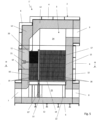
- the interior space 3 is spanned by a grid structure 14 which has a horizontal orientation and is attached to the side walls 6 and the partition wall 13 and/or stands on the container bottom 5 via feet 22.
- the grid structure 14 forms a support structure or support construction.
- the shaped blocks 18 extend from the grid structure 14 to close to the upper edge of the partition wall 13 and encompass, as Figure 3 can be seen, the partition wall 13 on its three sides.
- the heater chamber 16 forms a heating channel which is delimited at the bottom by the grid structure 14 and on which a stack of shaped blocks 19 is arranged as a support structure, each of which also has a honeycomb structure and corresponds to the shaped blocks 18 arranged in the storage chamber 15.
- the stack of shaped blocks 19 has a height which is lower than that of the shaped blocks 18 in the storage chamber 15.
- a heating arrangement 20 is arranged on the shaped blocks 19, which represents an electrical heating device and is connected via connections 21 to a power source, for example to a wind turbine, a photovoltaic system and/or the power grid.
- An upper side of the heating arrangement 20 is approximately flush with the upper side of the heat storage medium 17 in the storage chamber 15.
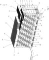
- FIG 7 the heating arrangement 20 of the heating system arranged in the heater room 16 of the heat storage devices described above is shown in isolation.
- the heating arrangement 20 is provided on the bottom with two rows of six shaped blocks 26 arranged one behind the other, which form a support structure and each have a honeycomb structure and whose channels formed by the honeycombs allow flow in the vertical direction.
- the shaped blocks 26 are ceramic shaped blocks made from cordierite.
- a number of layers 27 are arranged on the heating arrangement 20, each of which is formed from, in the present case, six heating units 28 arranged next to one another.
- the heating arrangement 20 is delimited by a layer of shaped blocks 30 arranged next to one another, which form a cover 29 and which also have a honeycomb structure and whose channels formed by the honeycombs are aligned in the vertical direction and through which flow can pass.
- the heating arrangement 20 also comprises two connection contacts 31 and 32, which are connected to a power source or a power network.
- the base plates 35 of the bearing elements 33 each have a recess 37 with a rectangular cross-section in the area of the lateral edges, into which the top of the relevant side wall 36 of the underlying bearing element 33 engages when stacked. This ensures that the bearing elements 33 arranged one above the other are arranged in a precise position.
- Upper ribs of the shaped blocks 26 engage in the recesses 37 of the lowest layer of heating units 28.
- the side walls 36 are provided on their upper side with a seal 38, which consists for example of a ceramic paper (cf. Fig. 8 ).
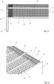
- the heating devices 34 of the heating units 28 are essentially identical in construction and each have a flow base area, which in the present case corresponds to the area between the side walls 36 of two bearing elements 33 arranged one behind the other. In the installed position, the heating device 34 rests on the base plates 35 of these two bearing elements 33. As can be seen in particular from the Figures 9 to 11 As can be seen, the heating devices 34 each comprise six heating plate units 39A, 39B, 39C, 39D, 39E and 39F, which are connected in series.
- the heating plate units 39A and 39B, the heating plate units 39B and 39C, the heating plate units 39C and 39D, the heating plate units 39D and 39E and the heating plate units 39E and 39F are each connected to one another via a contact plate 40, which is arranged on a respective end face of the heating device 34.
- a partition wall 41 is arranged between adjacent heating plate units, which is made of an electrically insulating material, for example a ceramic material, and also ensures electrical insulation between adjacent contact plates 40.
- the heating device 34 comprises side walls 42 which, in the installed position, border on or rest against the relevant side walls 36 of the relevant two bearing elements 33.
- the heating device 34 has a first connection element 43 and a second connection element 44, wherein the connection elements 43 and 44 are each formed from a sheet metal part which is aligned with the contact plates 40 which are arranged on the relevant end face of the heating device 34.
- the connection element 43 is electrically connected to an end face of the heating plate unit 39A, whereas the connection element 44 is electrically connected to an end face of the heating plate unit 39F.
- the individual heating plate units 39A, 39B, 39C, 39D, 39E and 39F each comprise a plurality of heating plate strips 45 and 46.
- corrugated heating sheet strips 45 and flat heating sheet strips 46 are arranged one behind the other in the stacking direction, with the corrugated heating sheet strips 45 being supported with their wave crests on the adjacent flat heating sheet strips 46.
- the outer corrugated heating sheet strips 45 are also supported on the relevant partition wall 41 or the relevant side wall 42.
- the heating plate strips 45 and 46 are aligned parallel to one another and are each connected to one another via a spacer structure 47, which also establishes the contact between the heating plate stack in question and the connection element 43 or 44 or the contact plate 40 in question.
- the spacer structure 47 comprises lining plates 48 designed as spacer elements, which are arranged between the parallel end regions of adjacent heating plate strips and are welded or soldered to them.
- the lining plates 48 each have a thickness that corresponds to the amplitude of the corrugation of the corrugated heating plate strips 45.
- the corrugation of the heating plate strips 45 forms a honeycomb structure which provides a large inflow area for the gas flow flowing through the heating device 34.
- lining plates can also be arranged between adjacent heating plate strips. It is also conceivable that the spacer structure is formed from a comb structure into which the end regions of the heating plate strips are inserted.
- the heating devices of the heating units in the various layers 27 of the heating arrangement 20 have different heights and/or different honeycomb channel shapes.
- the heating devices 34 of a layer 27 of the heating arrangement 20 are connected in series via contact plates 49. It is of course also conceivable to connect them in parallel. Furthermore, in the present embodiment, successive layers are connected in parallel in pairs via contact strips 50. In principle, the connection of the heating devices 34 can be selected as required.
- thermocouple 51 is arranged in the cover 29 in a transverse bore of a shaped block 30.
- a heat storage device 60 is shown, which largely corresponds to that according to the Figures 1 to 3 but differs from it in that it does not comprise a stack heater of the type described above in the heater chamber 16, which forms a heating channel. Rather, resistance heating elements 61, which are formed from heating coils or the like and are connected to a power grid via a connection area 62, engage in the heater chamber 16. In other respects, the heat storage device 60 corresponds to that according to the Figures 1 to 3 , which is why reference is made to the relevant description.
- the heat storage device 60 can be switched to a loading mode by means of corresponding valves, in which a gas flow consisting of warm air is introduced via a loading opening 7.
- This gas flow is, as Figure 13 can be seen, is guided from bottom to top in the heater chamber 16 and heated by means of the resistance heating elements 61 and passed through the gas distribution chamber 24, which forms an open volume, through the heat storage medium 17, which is made up of the shaped blocks 19.
- the shaped blocks 19 are thereby charged, i.e. heated.
- the gas flow which is then cooled again, is led out of the heat storage device 60 again via the gas distribution chamber 25 and the inlet/outlet opening 8.
- a gas stream consisting of warm air is introduced into the heat storage device via the inlet/outlet opening 8 and is then passed from bottom to top through the gas distribution chamber 25 through the heat storage medium 17 formed from the shaped blocks 19 and is heated there. After heating, the heated gas stream is discharged from the heat storage device via the upper gas distribution chamber 24 and the discharge opening 9 for further use.
- FIG 15 A heating operation without heat storage is shown for the heat storage device 60.
- a warm air gas flow is fed through the loading opening 7 into the heat storage device and heated in the heater chamber 16 by means of the resistance heating elements 61 and then discharged as a hot air gas stream via the upper gas distribution chamber 24 and the discharge opening 9 from the heat storage device 60.
- the described heat storage device 60 can also be operated in such a way that a warm air gas flow is introduced into the heat storage device via the loading opening 7 and heated by means of the resistance heating elements 61.
- the resulting hot air gas flow is divided in the upper gas distribution space 24 and on the one hand discharged from the heat storage device 60 via the discharge opening 9 and on the other hand passed through the heat storage medium 17 formed from the shaped blocks 19 to load it and then discharged from the heat storage device via the lower gas distribution space 25 and the inlet/outlet opening 8.
- the heat storage device 60 can be operated in such a way that a warm air gas flow is introduced via the loading opening 7 and the inlet/outlet opening 8.
- the gas flow introduced via the loading opening 7 is guided vertically upwards in the heater chamber 16 and heated by means of the resistance heating elements 61 and discharged via the upper gas distribution chamber 24 and the discharge opening 9.
- the warm air gas flow introduced via the inlet/outlet opening 8 is guided through the loaded heat storage medium 17 and heated there by heat exchange in order to then also be discharged from the heat storage device via the upper gas distribution chamber 24 and the discharge opening 9.
- a heat storage system 70 which comprises a heat storage device 71 which can be configured either according to the Figures 1 to 6 embodiments shown or in accordance with the Figures 12 to 17
- the heat storage system 70 comprises a line arrangement 72 which is connected to a consumer 73, which for example can be designed as a steam generator of a power plant.
- the line arrangement 72 comprises a line 74 which connects the discharge opening 9 of the heat storage device 71 to an inlet 75 of the consumer 73.
- the loading opening 7 of the heat storage device 71 is connected to a line 76 of the line arrangement 72, and the inlet/outlet opening 8 of the heat storage device 71 is connected to a line 77 of the line arrangement 72.
- An outlet 78 of the consumer 73 is connected to a line 79 which leads to a fan 80 which in turn is connected via the line 76 to the loading opening 7 of the heat storage device 71.
- a branch line 81 branches off from the line 76 and is connected to the line 77.
- a branch line 82 branches off from the line 79, which is also connected to the line 77.
- a valve 83 is arranged in the line 76, a valve 84 is arranged in the branch line 81, a valve 85 is arranged in the branch line 82 and a valve 86 is arranged in the line 79 upstream of the branch of the branch line 82.
- a valve 84 is arranged in the branch line 81
- a valve 85 is arranged in the branch line 82
- a valve 86 is arranged in the line 79 upstream of the branch of the branch line 82.
- other suitable shut-off valves such as flaps or the like, can of course also be used.
- the heat storage device 71 is connected to a power source 87, which can be formed by the power grid or also a photovoltaic system or even a wind turbine and is provided with a switch 88.
- a warm air gas flow is introduced from below into the heater chamber 16 of the heat storage device 71 via the loading opening 7 by means of the blower 80 with the valve 83 open.
- the switch 88 is closed so that the heater arrangement is operated and the gas flow in the heater chamber 16 is heated.
- the heated gas flow is guided via the upper gas distribution chamber 24 into the storage chamber 15 and passed from top to bottom through the heat storage bed formed by the heat storage medium 17, the heat being released to it and stored there.
- a warm air gas stream is then discharged via the inlet/outlet opening 8 from the heat storage device 71 and guided via the line 77 and the branch line 82 to the blower 80 in order to then be fed back to the heat storage device 71 in the manner described above.
- the valves 84 and 86 are closed in this loading mode.
- valves 84 and 86 are opened and valves 83 and 85 are closed.
- warm air is then introduced into the heat storage device 71 from below via the branch line 81 and the line 77 and the inlet/outlet opening 8 and is heated in the storage bed formed by the heat storage medium 17.
- the resulting hot air gas flow is discharged from the top of the heat storage device 71 via the discharge opening 9 and made available to the consumer 73 via the line 74.
- the consumer in turn releases warm air, which can be fed back to the heat storage device 71 by means of the blower 80 in the manner described above.
- valves 84 and 85 are closed, whereas the valves 83 and 86 are open.
- warm air can then be introduced into the heating chamber 16 of the heat storage device 71 and heated there.
- the resulting hot air gas flow is led out of the heat storage device 71 via the discharge opening 9 and then fed to the consumer 73 via the line 74.
- the consumer 73 in turn emits a warm air gas flow, which is led to the fan 80 via the line 79 and can be fed back into the heat storage device 71 in the manner described above.
- An embodiment of a heat storage system (not shown in detail) can be designed as an at least partially open system in which the air exiting the consumer is completely or partially released into the environment. When the heat storage device is discharged, a corresponding amount of ambient air is then sucked in on the suction side of the fan. Otherwise, this embodiment can correspond to the embodiment described above.
Landscapes
- Engineering & Computer Science (AREA)
- Physics & Mathematics (AREA)
- Thermal Sciences (AREA)
- Mechanical Engineering (AREA)
- General Engineering & Computer Science (AREA)
- Chemical & Material Sciences (AREA)
- Combustion & Propulsion (AREA)
- Dispersion Chemistry (AREA)
- Central Heating Systems (AREA)
- Resistance Heating (AREA)
- Direct Air Heating By Heater Or Combustion Gas (AREA)
- Surface Heating Bodies (AREA)
- Heat-Pump Type And Storage Water Heaters (AREA)
- Pipe Accessories (AREA)
- Wind Motors (AREA)
- Thermal Insulation (AREA)
Claims (15)
- Système de chauffage pour un courant de gaz, le système de chauffage comprenant un côté d'entrée et un côté de sortie et un ensemble de chauffage (20), qui comprend au moins une unité de chauffage (28), qui comprend un dispositif de chauffage (34) ayant une zone de base d'écoulement, qui est perpendiculaire au courant de gaz, et au moins un élément de montage (33), sur lequel le dispositif de chauffage (34) est disposé et qui est perméable au courant de gaz de sorte que le courant de gaz puisse s'écouler sur la zone de base d'écoulement du dispositif de chauffage (34) ou que le courant de gaz puisse s'écouler du dispositif de chauffage (34) à travers l'élément de montage (33), caractérisé en ce que l'élément de montage (33) comprend une brique moulée dans laquelle sont formés les conduits d'écoulement qui mènent au dispositif de chauffage (34), ou en ce que l'élément de montage est constitué de tiges de céramique, d'une plaque ou d'un panneau perforé.
- Système de chauffage selon la revendication 1, caractérisé en ce que l'élément de montage (33) est constitué d'un matériau de travail électriquement isolant, résistant à la chaleur, en particulier en céramique.
- Système de chauffage selon l'une quelconque des revendications 1 à 2, caractérisé en ce que l'élément de montage (33) a une surface de support qui correspond à la zone de base d'écoulement du dispositif de chauffage (34).
- Système de chauffage selon l'une quelconque des revendications 1 à 3, caractérisé en ce que l'élément de montage (33) est équipé de parois latérales (36) qui délimitent latéralement le dispositif de chauffage (34) et est formé pour être étanche au gaz.
- Système de chauffage selon la revendication 4, caractérisé en ce que les parois latérales (36) sont réalisées en une seule pièce avec l'élément de montage (33).
- Système de chauffage selon l'une quelconque des revendications 1 à 5, caractérisé en ce que l'ensemble de chauffage (20) comprend plusieurs unités de chauffages (28), qui sont adjacentes les unes aux autres.
- Système de chauffage selon l'une quelconque des revendications 1 à 6, caractérisé en ce que l'ensemble de chauffage (20) comprend plusieurs unités de chauffage (28), qui sont superposées.
- Système de chauffage selon la revendication 7, caractérisé en ce que les unités de chauffage (28) superposées sont sécurisées contre un déplacement relatif au moyen d'une sécurité de roulement.
- Système de chauffage selon l'une quelconque des revendications 1 à 8, caractérisé en ce que l'ensemble de chauffage (20) a un couvercle (29) à travers lequel le courant de gaz peut passer et qui forme la face supérieure de l'ensemble de chauffage (20) et qui est de préférence constitué d'une brique moulée (30).
- Système de chauffage selon l'une quelconque des revendications 1 à 9, caractérisé en ce que l'ensemble de chauffage (20) est disposé sur une structure porteuse.
- Système de chauffage selon la revendication 10, caractérisé en ce que la structure porteuse comprend une structure en grille (14) sur laquelle repose l'ensemble de chauffage (20).
- Système de chauffage selon la revendication 10 ou 11, caractérisé en ce que la structure porteuse comprend au moins une brique moulée (26) et/ou un remplissage, de préférence au moins une brique moulée alvéolée.
- Système de chauffage selon l'une quelconque des revendications 1 à 12, caractérisé en ce que la structure porteuse comprend au moins un canal de déviation des gaz.
- Système de chauffage selon l'une quelconque des revendications 1 à 13, caractérisé par un conduit de chauffage dans lequel l'ensemble de chauffage (20) est disposé et qui a de préférence une isolation intérieure (12).
- Système de chauffage selon la revendication 1 à 14, caractérisé en ce que le dispositif de chauffage comprend deux éléments de connexion (43, 44) électriques pour être reliés à une source d'énergie et au moins une unité (39A, 39B, 39C, 39D, 39E, 39F) de plaque de chauffage ayant un côté d'entrée et un côté de sortie, qui comprend une pluralité de lames (45, 46) de plaque de chauffage qui sont dans le courant de gaz et ont chacune une première zone d'extrémité et une deuxième zone d'extrémité, les lames (45, 46) de plaque de chauffage adjacentes étant reliées les unes aux autres dans les premières zones d'extrémité et les deuxièmes zones d'extrémité par l'intermédiaire d'une structure d'entretoise (47) conductrice, la structure d'entretoise conductrice (47) comprenant des plaques de revêtement (48), qui sont disposées entre les lames (45, 46) de plaque de chauffage adjacentes et les relient les unes aux autres, et/ou une structure en peigne, qui reçoit les lames de plaque de chauffage.
Priority Applications (4)
| Application Number | Priority Date | Filing Date | Title |
|---|---|---|---|
| SI202130249T SI4253892T1 (sl) | 2020-05-04 | 2021-04-29 | Ogrevalna naprava, ogrevalni sistem, naprava za shranjevanje toplote in sistem za shranjevanje toplote |
| MA64769A MA64769B1 (fr) | 2020-05-04 | 2021-04-29 | Dispositif de chauffage, système de chauffage, dispositif de stockage d'énergie thermique et système de stockage d'énergie thermique |
| HRP20241785TT HRP20241785T1 (hr) | 2020-05-04 | 2021-04-29 | Uređaj za grijanje, sustav za grijanje, uređaj za skladištenje topline i sustav za skladištenje topline |
| RS20241426A RS66413B1 (sr) | 2020-05-04 | 2021-04-29 | Uređaj za grejanje, sistem za grejanje, uređaj za skladištenje toplote i sistem za skladištenje toplote |
Applications Claiming Priority (3)
| Application Number | Priority Date | Filing Date | Title |
|---|---|---|---|
| DE102020111987.9A DE102020111987B4 (de) | 2020-05-04 | 2020-05-04 | Heizeinrichtung |
| EP21725419.2A EP4146915B1 (fr) | 2020-05-04 | 2021-04-29 | Dispositif de chauffage, systeme de chauffage, appareil de stockage thermique et systeme de stockage thermique |
| PCT/EP2021/061303 WO2021224109A1 (fr) | 2020-05-04 | 2021-04-29 | Dispositif de chauffage, système de chauffage, dispositif de stockage d'énergie thermique et système de stockage d'énergie thermique |
Related Parent Applications (2)
| Application Number | Title | Priority Date | Filing Date |
|---|---|---|---|
| EP21725419.2A Division-Into EP4146915B1 (fr) | 2020-05-04 | 2021-04-29 | Dispositif de chauffage, systeme de chauffage, appareil de stockage thermique et systeme de stockage thermique |
| EP21725419.2A Division EP4146915B1 (fr) | 2020-05-04 | 2021-04-29 | Dispositif de chauffage, systeme de chauffage, appareil de stockage thermique et systeme de stockage thermique |
Publications (3)
| Publication Number | Publication Date |
|---|---|
| EP4253892A2 EP4253892A2 (fr) | 2023-10-04 |
| EP4253892A3 EP4253892A3 (fr) | 2023-11-15 |
| EP4253892B1 true EP4253892B1 (fr) | 2024-11-20 |
Family
ID=75914487
Family Applications (3)
| Application Number | Title | Priority Date | Filing Date |
|---|---|---|---|
| EP23193090.0A Active EP4253892B1 (fr) | 2020-05-04 | 2021-04-29 | Dispositif de chauffage, système de chauffage, dispositif de stockage d'énergie thermique et système de stockage d'énergie thermique |
| EP21725419.2A Active EP4146915B1 (fr) | 2020-05-04 | 2021-04-29 | Dispositif de chauffage, systeme de chauffage, appareil de stockage thermique et systeme de stockage thermique |
| EP23193075.1A Active EP4257907B1 (fr) | 2020-05-04 | 2021-04-29 | Dispositif de chauffage, système de chauffage, dispositif de stockage d'énergie thermique et système de stockage d'énergie thermique |
Family Applications After (2)
| Application Number | Title | Priority Date | Filing Date |
|---|---|---|---|
| EP21725419.2A Active EP4146915B1 (fr) | 2020-05-04 | 2021-04-29 | Dispositif de chauffage, systeme de chauffage, appareil de stockage thermique et systeme de stockage thermique |
| EP23193075.1A Active EP4257907B1 (fr) | 2020-05-04 | 2021-04-29 | Dispositif de chauffage, système de chauffage, dispositif de stockage d'énergie thermique et système de stockage d'énergie thermique |
Country Status (22)
| Country | Link |
|---|---|
| US (1) | US20230194124A1 (fr) |
| EP (3) | EP4253892B1 (fr) |
| JP (3) | JP7598947B2 (fr) |
| CN (1) | CN115605671B (fr) |
| AU (4) | AU2021268992A1 (fr) |
| BR (1) | BR112022021825A2 (fr) |
| CA (3) | CA3263845A1 (fr) |
| CL (2) | CL2022003064A1 (fr) |
| DE (1) | DE102020111987B4 (fr) |
| DK (3) | DK4257907T3 (fr) |
| ES (3) | ES3014516T3 (fr) |
| FI (3) | FI4257907T3 (fr) |
| HR (3) | HRP20241785T1 (fr) |
| HU (3) | HUE073313T2 (fr) |
| LT (3) | LT4257907T (fr) |
| MA (2) | MA65243B1 (fr) |
| PL (3) | PL4253892T3 (fr) |
| PT (3) | PT4257907T (fr) |
| RS (1) | RS66413B1 (fr) |
| SI (3) | SI4257907T1 (fr) |
| WO (1) | WO2021224109A1 (fr) |
| ZA (1) | ZA202211237B (fr) |
Families Citing this family (2)
| Publication number | Priority date | Publication date | Assignee | Title |
|---|---|---|---|---|
| US12467696B2 (en) | 2022-03-14 | 2025-11-11 | Timothy Patrick Cooper | Cooking apparatus with thermal energy storage system |
| EP4481293A1 (fr) * | 2023-06-19 | 2024-12-25 | Heatrix GmbH | Dispositif de chauffage électrique et procédé de fourniture de chaleur de traitement |
Family Cites Families (43)
| Publication number | Priority date | Publication date | Assignee | Title |
|---|---|---|---|---|
| DE489379C (de) * | 1927-11-25 | 1930-01-17 | Siemens Schuckertwerke Akt Ges | Elektrischer Winderhitzer |
| DE718229C (de) * | 1937-11-30 | 1942-03-06 | Alessandru Beldimano | Verfahren und Vorrichtung zur Entnahme von Waermeenergie aus Waermespeichern |
| US3111979A (en) * | 1960-03-07 | 1963-11-26 | Lennox Ind Inc | Dual fuel burner construction |
| DE1779952A1 (de) * | 1967-02-22 | 1972-05-25 | Everken Olsberger Huette Kg | Elektrischer Speicherofen |
| GB1267803A (en) * | 1968-04-03 | 1972-03-22 | Laporte Titanium Ltd | Improvements in and relating to the heating of gases |
| CA933993A (en) * | 1970-12-09 | 1973-09-18 | J. Fedor Robert | Electric resistance heating element |
| DE2432904A1 (de) * | 1973-07-19 | 1975-02-06 | Atomic Energy Authority Uk | Heizelement zum erhitzen von stroemungsmitteln |
| DE2451736C3 (de) * | 1974-10-31 | 1979-03-01 | G. Bauknecht Gmbh, Elektrotechnische Fabriken, 7000 Stuttgart | Speicherheizgerät |
| GB1551818A (en) * | 1975-05-06 | 1979-09-05 | Ti Creda Mfg | Air heating devices |
| JPS5553100Y2 (fr) * | 1975-11-07 | 1980-12-09 | ||
| GB1523316A (en) * | 1975-11-20 | 1978-08-31 | Standard Telephones Cables Ltd | Electric resistance heaters |
| JPS5553106Y2 (fr) * | 1976-06-10 | 1980-12-09 | ||
| DE2731115C2 (de) * | 1977-07-09 | 1982-09-23 | Didier-Werke Ag, 6200 Wiesbaden | Wärmespeicheranlage |
| US4286141A (en) * | 1978-06-22 | 1981-08-25 | Calmac Manufacturing Corporation | Thermal storage method and system utilizing an anhydrous sodium sulfate pebble bed providing high-temperature capability |
| JPS55111049U (fr) * | 1979-01-29 | 1980-08-04 | ||
| US4346285A (en) * | 1979-04-28 | 1982-08-24 | Murata Manufacturing Co., Ltd. | Heating device employing thermistor with positive coefficient characteristic |
| US4362149A (en) * | 1980-12-08 | 1982-12-07 | Rockwell International Corporation | Heat storage system and method |
| DE8322435U1 (de) * | 1983-08-03 | 1985-05-30 | Grote & Hartmann Gmbh & Co Kg, 5600 Wuppertal | Widerstandsheizelement |
| GB2152652A (en) * | 1984-01-09 | 1985-08-07 | Powramtic Limited | An electric storage heater |
| NO157640C (no) * | 1985-07-09 | 1988-04-20 | Nielsen Ingenioer Og Handelsak | Varmeaggregat. |
| JPH04344069A (ja) * | 1991-05-20 | 1992-11-30 | Mitsubishi Heavy Ind Ltd | 蓄熱装置 |
| JP2547608Y2 (ja) * | 1991-06-25 | 1997-09-10 | シャープ株式会社 | 空気加熱兼浄化装置 |
| DE19724734C2 (de) * | 1997-06-12 | 2000-06-29 | Behr Gmbh & Co | Elektrische Heizeinrichtung, insbesondere für ein Kraftfahrzeug |
| EP0937595B1 (fr) * | 1998-02-20 | 2003-08-20 | smart gmbh | Installation de chauffage ou de climatisation pour véhicules |
| IT249474Y1 (it) | 2000-02-17 | 2003-05-19 | Eltek Spa | Radiatore elettrico. |
| JP2005001447A (ja) | 2003-06-10 | 2005-01-06 | Denso Corp | 電気ヒータ、暖房用熱交換器および車両用空調装置 |
| DE102005001385B3 (de) * | 2004-12-22 | 2006-08-24 | Schütz GmbH & Co. KGaA | Elektrisches Luftheizregister |
| JP4302677B2 (ja) * | 2005-08-17 | 2009-07-29 | 中国電力株式会社 | 給湯配管再加熱システム、給湯システム、及び給湯方法 |
| JP3116121U (ja) | 2005-08-26 | 2005-11-24 | 林 正 平 | 発熱板を用いた発熱装置 |
| DE102008030212A1 (de) * | 2007-10-18 | 2009-04-23 | Stego-Holding Gmbh | Heizvorrichtung und Wärmetauscher |
| KR100906938B1 (ko) | 2007-12-06 | 2009-07-10 | (주)하이코 | 온풍기용 면상 발열체 |
| AT506477B1 (de) | 2008-02-21 | 2010-07-15 | Schweighofer Franz | Wärmespeichereinrichtung |
| KR20100055262A (ko) * | 2008-11-17 | 2010-05-26 | 현대자동차주식회사 | 고용량 피티씨 히터 |
| EP2730854B1 (fr) * | 2012-11-12 | 2015-06-03 | Betacera Inc. | Chauffage du compartiment intérieur de voiture |
| DE102013108319B4 (de) * | 2013-08-01 | 2016-10-20 | B + S Entwicklungsgesellschaft Mbh | Verfahren sowie Vorrichtung zur Energiespeicherung |
| KR101614523B1 (ko) * | 2014-04-25 | 2016-04-21 | 김형석 | 전기 히터식 제해 장치 및 이에 사용되는 전기 히터 구조체 |
| JP2016102615A (ja) * | 2014-11-28 | 2016-06-02 | パナホーム株式会社 | 蓄熱構造体 |
| JP6511636B2 (ja) * | 2015-01-28 | 2019-05-15 | パナソニックIpマネジメント株式会社 | ヒーター付きエアカーテン |
| EP3051223B1 (fr) * | 2015-01-28 | 2017-11-08 | Mahle International GmbH | Dispositif de chauffage électrique |
| EP3296660A1 (fr) * | 2016-09-15 | 2018-03-21 | Mahle International GmbH | Chauffage électrique |
| DE102017207691B4 (de) * | 2017-05-08 | 2026-03-12 | Fritz GmbH & Co. KG | Stationäres Lagersystem für Batterien |
| JP6744884B2 (ja) * | 2018-03-06 | 2020-08-19 | 川崎重工業株式会社 | 貯気槽 |
| DE102019120448B4 (de) * | 2019-07-29 | 2024-03-07 | Kraftanlagen München Gmbh | Wärmespeichervorrichtung, Wärmespeichersystem und Verfahren zum Betreiben einer Wärmespeichervorrichtung |
-
2020
- 2020-05-04 DE DE102020111987.9A patent/DE102020111987B4/de active Active
-
2021
- 2021-04-29 SI SI202130337T patent/SI4257907T1/sl unknown
- 2021-04-29 DK DK23193075.1T patent/DK4257907T3/da active
- 2021-04-29 AU AU2021268992A patent/AU2021268992A1/en not_active Abandoned
- 2021-04-29 FI FIEP23193075.1T patent/FI4257907T3/fi active
- 2021-04-29 ES ES23193090T patent/ES3014516T3/es active Active
- 2021-04-29 LT LTEP23193075.1T patent/LT4257907T/lt unknown
- 2021-04-29 PL PL23193090.0T patent/PL4253892T3/pl unknown
- 2021-04-29 EP EP23193090.0A patent/EP4253892B1/fr active Active
- 2021-04-29 SI SI202130249T patent/SI4253892T1/sl unknown
- 2021-04-29 ES ES23193075T patent/ES3040457T3/es active Active
- 2021-04-29 PT PT231930751T patent/PT4257907T/pt unknown
- 2021-04-29 WO PCT/EP2021/061303 patent/WO2021224109A1/fr not_active Ceased
- 2021-04-29 HR HRP20241785TT patent/HRP20241785T1/hr unknown
- 2021-04-29 CA CA3263845A patent/CA3263845A1/fr active Pending
- 2021-04-29 FI FIEP23193090.0T patent/FI4253892T3/fi active
- 2021-04-29 HU HUE21725419A patent/HUE073313T2/hu unknown
- 2021-04-29 JP JP2022566121A patent/JP7598947B2/ja active Active
- 2021-04-29 DK DK21725419.2T patent/DK4146915T3/da active
- 2021-04-29 HR HRP20251009TT patent/HRP20251009T1/hr unknown
- 2021-04-29 MA MA65243A patent/MA65243B1/fr unknown
- 2021-04-29 HR HRP20251030TT patent/HRP20251030T1/hr unknown
- 2021-04-29 CA CA3181353A patent/CA3181353A1/fr active Pending
- 2021-04-29 LT LTEPPCT/EP2021/061303T patent/LT4146915T/lt unknown
- 2021-04-29 HU HUE23193090A patent/HUE069841T2/hu unknown
- 2021-04-29 LT LTEP23193090.0T patent/LT4253892T/lt unknown
- 2021-04-29 ES ES21725419T patent/ES3039008T3/es active Active
- 2021-04-29 PL PL21725419.2T patent/PL4146915T3/pl unknown
- 2021-04-29 PL PL23193075.1T patent/PL4257907T3/pl unknown
- 2021-04-29 CA CA3263841A patent/CA3263841A1/en active Pending
- 2021-04-29 EP EP21725419.2A patent/EP4146915B1/fr active Active
- 2021-04-29 FI FIEP21725419.2T patent/FI4146915T3/fi active
- 2021-04-29 MA MA64769A patent/MA64769B1/fr unknown
- 2021-04-29 US US17/923,349 patent/US20230194124A1/en active Pending
- 2021-04-29 DK DK23193090.0T patent/DK4253892T3/da active
- 2021-04-29 CN CN202180033167.6A patent/CN115605671B/zh active Active
- 2021-04-29 SI SI202130338T patent/SI4146915T1/sl unknown
- 2021-04-29 EP EP23193075.1A patent/EP4257907B1/fr active Active
- 2021-04-29 RS RS20241426A patent/RS66413B1/sr unknown
- 2021-04-29 PT PT231930900T patent/PT4253892T/pt unknown
- 2021-04-29 PT PT217254192T patent/PT4146915T/pt unknown
- 2021-04-29 HU HUE23193075A patent/HUE073294T2/hu unknown
- 2021-04-29 BR BR112022021825A patent/BR112022021825A2/pt unknown
-
2022
- 2022-10-13 ZA ZA2022/11237A patent/ZA202211237B/en unknown
- 2022-11-04 CL CL2022003064A patent/CL2022003064A1/es unknown
-
2024
- 2024-06-24 AU AU2024204295A patent/AU2024204295B2/en active Active
- 2024-06-24 AU AU2024204294A patent/AU2024204294A1/en active Pending
- 2024-07-05 JP JP2024108899A patent/JP2024129136A/ja active Pending
- 2024-07-05 JP JP2024108892A patent/JP7759443B2/ja active Active
- 2024-07-29 CL CL2024002282A patent/CL2024002282A1/es unknown
-
2025
- 2025-02-28 AU AU2025201491A patent/AU2025201491A1/en active Pending
Also Published As
Similar Documents
| Publication | Publication Date | Title |
|---|---|---|
| EP3997405B1 (fr) | Dispositif de stockage de chaleur, système de stockage de chaleur et procédé pour faire fonctionner un dispositif de stockage de chaleur | |
| EP2247906B1 (fr) | Dispositif accumulateur de chaleur | |
| EP3655631B1 (fr) | Réservoir d'énergie permettant le stockage d'énergie électrique en tant que chaleur et procédé correspondant | |
| DE102007046133B4 (de) | Wärmespeicher zur Speicherung von Energie | |
| EP2601456B1 (fr) | Accumulateur de chaleur haute température pour centrales solaires thermiques | |
| EP4253892B1 (fr) | Dispositif de chauffage, système de chauffage, dispositif de stockage d'énergie thermique et système de stockage d'énergie thermique | |
| WO2010060524A1 (fr) | Dispositif et installation de stockage temporaire d'énergie thermique | |
| DE202020102486U1 (de) | Heizeinrichtung, Heizsystem, Wärmespeichervorrichtung und Wärmespeichersystem | |
| AT520477B1 (de) | Vorrichtung zum Erzeugen von Dampf | |
| DE102020008102A1 (de) | Wärmespeichervorrichtung und Wärmespeichersystem | |
| DE102020008100A1 (de) | Heizsystem | |
| DE3208378C2 (de) | Deckenstrahlungsheizung, insbesondere für Hallen | |
| DE2731391A1 (de) | Vorrichtung zur nutzbarmachung der restwaerme eines abgases | |
| WO2021013965A1 (fr) | Matériau mcp, dispositif de chauffage et procédé de chauffage | |
| EP2015006A2 (fr) | Pompe à chaleur | |
| DE102006024341A1 (de) | Aufwindkraftwerk | |
| DE102011119117B4 (de) | Sorptionstechnisches Gerät zur Speicherung und Wandlung von Energie verschiedener Zustandsformen | |
| WO2023057439A1 (fr) | Concept de protection pour matériau d'accumulation d'un accumulateur thermique, installation à cycle combiné et procédé | |
| WO2025002992A1 (fr) | Dispositif de stockage de chaleur doté de cartouches de dispositif de stockage de chaleur | |
| CH721499A2 (de) | Verfahren und Vorrichtung zum Speichern von Wärme | |
| DE7721822U1 (de) | Vorrichtung zur nutzbarmachung der restwaerme eines abgases | |
| EP4229348A1 (fr) | Module de stockage, plaque de stockage de chaleur et dispositif de stockage de chaleur | |
| DE102007058030A1 (de) | Abkühlanordnung | |
| DE102016100365A1 (de) | Verfahren zum Erwärmen, vorzugsweise Erhitzen, eines Guts und/oder eines, vorzugweise gasförmigen, Prozessmediums in einem in einer Prozessanlage ablaufenden Prozess | |
| DE1758267B1 (de) | Kuehlkamin |
Legal Events
| Date | Code | Title | Description |
|---|---|---|---|
| REG | Reference to a national code |
Ref country code: HR Ref legal event code: TUEP Ref document number: P20241785T Country of ref document: HR |
|
| PUAI | Public reference made under article 153(3) epc to a published international application that has entered the european phase |
Free format text: ORIGINAL CODE: 0009012 |
|
| STAA | Information on the status of an ep patent application or granted ep patent |
Free format text: STATUS: THE APPLICATION HAS BEEN PUBLISHED |
|
| AC | Divisional application: reference to earlier application |
Ref document number: 4146915 Country of ref document: EP Kind code of ref document: P |
|
| AK | Designated contracting states |
Kind code of ref document: A2 Designated state(s): AL AT BE BG CH CY CZ DE DK EE ES FI FR GB GR HR HU IE IS IT LI LT LU LV MC MK MT NL NO PL PT RO RS SE SI SK SM TR |
|
| REG | Reference to a national code |
Free format text: PREVIOUS MAIN CLASS: F28D0017040000 Ref country code: DE Ref legal event code: R079 Ref document number: 502021005909 Country of ref document: DE Ipc: F01K0003000000 |
|
| PUAL | Search report despatched |
Free format text: ORIGINAL CODE: 0009013 |
|
| AK | Designated contracting states |
Kind code of ref document: A3 Designated state(s): AL AT BE BG CH CY CZ DE DK EE ES FI FR GB GR HR HU IE IS IT LI LT LU LV MC MK MT NL NO PL PT RO RS SE SI SK SM TR |
|
| RIC1 | Information provided on ipc code assigned before grant |
Ipc: F28D 17/04 20060101ALN20231009BHEP Ipc: F28D 17/02 20060101ALN20231009BHEP Ipc: H05B 3/24 20060101ALI20231009BHEP Ipc: H02J 15/00 20060101ALI20231009BHEP Ipc: F28D 20/00 20060101ALI20231009BHEP Ipc: F24H 7/04 20060101ALI20231009BHEP Ipc: F24H 3/04 20220101ALI20231009BHEP Ipc: F01K 3/00 20060101AFI20231009BHEP |
|
| STAA | Information on the status of an ep patent application or granted ep patent |
Free format text: STATUS: REQUEST FOR EXAMINATION WAS MADE |
|
| 17P | Request for examination filed |
Effective date: 20240226 |
|
| RAV | Requested validation state of the european patent: fee paid |
Extension state: TN Effective date: 20240226 Extension state: MA Effective date: 20240226 |
|
| RBV | Designated contracting states (corrected) |
Designated state(s): AL AT BE BG CH CY CZ DE DK EE ES FI FR GB GR HR HU IE IS IT LI LT LU LV MC MK MT NL NO PL PT RO RS SE SI SK SM TR |
|
| RAP3 | Party data changed (applicant data changed or rights of an application transferred) |
Owner name: KRAFTANLAGEN ENERGIES & SERVICES SE |
|
| GRAP | Despatch of communication of intention to grant a patent |
Free format text: ORIGINAL CODE: EPIDOSNIGR1 |
|
| STAA | Information on the status of an ep patent application or granted ep patent |
Free format text: STATUS: GRANT OF PATENT IS INTENDED |
|
| INTG | Intention to grant announced |
Effective date: 20240712 |
|
| GRAS | Grant fee paid |
Free format text: ORIGINAL CODE: EPIDOSNIGR3 |
|
| GRAA | (expected) grant |
Free format text: ORIGINAL CODE: 0009210 |
|
| STAA | Information on the status of an ep patent application or granted ep patent |
Free format text: STATUS: THE PATENT HAS BEEN GRANTED |
|
| AC | Divisional application: reference to earlier application |
Ref document number: 4146915 Country of ref document: EP Kind code of ref document: P |
|
| AK | Designated contracting states |
Kind code of ref document: B1 Designated state(s): AL AT BE BG CH CY CZ DE DK EE ES FI FR GB GR HR HU IE IS IT LI LT LU LV MC MK MT NL NO PL PT RO RS SE SI SK SM TR |
|
| REG | Reference to a national code |
Ref country code: GB Ref legal event code: FG4D Free format text: NOT ENGLISH Ref country code: TN Ref legal event code: VAGR Ref document number: TN/P/2024/000438 Country of ref document: TN |
|
| REG | Reference to a national code |
Ref country code: CH Ref legal event code: EP |
|
| REG | Reference to a national code |
Ref country code: DE Ref legal event code: R096 Ref document number: 502021005909 Country of ref document: DE |
|
| REG | Reference to a national code |
Ref country code: IE Ref legal event code: FG4D Free format text: LANGUAGE OF EP DOCUMENT: GERMAN |
|
| REG | Reference to a national code |
Ref country code: PT Ref legal event code: SC4A Ref document number: 4253892 Country of ref document: PT Date of ref document: 20241223 Kind code of ref document: T Free format text: AVAILABILITY OF NATIONAL TRANSLATION Effective date: 20241217 |
|
| REG | Reference to a national code |
Ref country code: FI Ref legal event code: FGE |
|
| REG | Reference to a national code |
Ref country code: MA Ref legal event code: VAGR Ref document number: 64769 Country of ref document: MA Kind code of ref document: B1 |
|
| REG | Reference to a national code |
Ref country code: DK Ref legal event code: T3 Effective date: 20241220 |
|
| REG | Reference to a national code |
Ref country code: SE Ref legal event code: TRGR |
|
| REG | Reference to a national code |
Ref country code: NL Ref legal event code: FP |
|
| REG | Reference to a national code |
Ref country code: SK Ref legal event code: T3 Ref document number: E 45653 Country of ref document: SK |
|
| REG | Reference to a national code |
Ref country code: GR Ref legal event code: EP Ref document number: 20250400165 Country of ref document: GR Effective date: 20250211 |
|
| PG25 | Lapsed in a contracting state [announced via postgrant information from national office to epo] |
Ref country code: IS Free format text: LAPSE BECAUSE OF FAILURE TO SUBMIT A TRANSLATION OF THE DESCRIPTION OR TO PAY THE FEE WITHIN THE PRESCRIBED TIME-LIMIT Effective date: 20250320 |
|
| PG25 | Lapsed in a contracting state [announced via postgrant information from national office to epo] |
Ref country code: BG Free format text: LAPSE BECAUSE OF FAILURE TO SUBMIT A TRANSLATION OF THE DESCRIPTION OR TO PAY THE FEE WITHIN THE PRESCRIBED TIME-LIMIT Effective date: 20241120 |
|
| REG | Reference to a national code |
Ref country code: ES Ref legal event code: FG2A Ref document number: 3014516 Country of ref document: ES Kind code of ref document: T3 Effective date: 20250423 |
|
| REG | Reference to a national code |
Ref country code: HU Ref legal event code: AG4A Ref document number: E069841 Country of ref document: HU |
|
| REG | Reference to a national code |
Ref country code: HR Ref legal event code: T1PR Ref document number: P20241785 Country of ref document: HR |
|
| PGFP | Annual fee paid to national office [announced via postgrant information from national office to epo] |
Ref country code: NL Payment date: 20250422 Year of fee payment: 5 |
|
| REG | Reference to a national code |
Ref country code: HR Ref legal event code: ODRP Ref document number: P20241785 Country of ref document: HR Payment date: 20250417 Year of fee payment: 5 |
|
| PG25 | Lapsed in a contracting state [announced via postgrant information from national office to epo] |
Ref country code: SM Free format text: LAPSE BECAUSE OF FAILURE TO SUBMIT A TRANSLATION OF THE DESCRIPTION OR TO PAY THE FEE WITHIN THE PRESCRIBED TIME-LIMIT Effective date: 20241120 |
|
| PGFP | Annual fee paid to national office [announced via postgrant information from national office to epo] |
Ref country code: FI Payment date: 20250417 Year of fee payment: 5 |
|
| PGFP | Annual fee paid to national office [announced via postgrant information from national office to epo] |
Ref country code: PL Payment date: 20250408 Year of fee payment: 5 Ref country code: DE Payment date: 20250617 Year of fee payment: 5 |
|
| PGFP | Annual fee paid to national office [announced via postgrant information from national office to epo] |
Ref country code: GB Payment date: 20250423 Year of fee payment: 5 Ref country code: ES Payment date: 20250519 Year of fee payment: 5 Ref country code: DK Payment date: 20250423 Year of fee payment: 5 |
|
| PGFP | Annual fee paid to national office [announced via postgrant information from national office to epo] |
Ref country code: LT Payment date: 20250416 Year of fee payment: 5 |
|
| PGFP | Annual fee paid to national office [announced via postgrant information from national office to epo] |
Ref country code: HU Payment date: 20250429 Year of fee payment: 5 Ref country code: RS Payment date: 20250416 Year of fee payment: 5 Ref country code: NO Payment date: 20250422 Year of fee payment: 5 |
|
| PGFP | Annual fee paid to national office [announced via postgrant information from national office to epo] |
Ref country code: IT Payment date: 20250430 Year of fee payment: 5 Ref country code: BE Payment date: 20250422 Year of fee payment: 5 |
|
| PGFP | Annual fee paid to national office [announced via postgrant information from national office to epo] |
Ref country code: HR Payment date: 20250417 Year of fee payment: 5 |
|
| PGFP | Annual fee paid to national office [announced via postgrant information from national office to epo] |
Ref country code: PT Payment date: 20250428 Year of fee payment: 5 Ref country code: LV Payment date: 20250422 Year of fee payment: 5 |
|
| PG25 | Lapsed in a contracting state [announced via postgrant information from national office to epo] |
Ref country code: EE Free format text: LAPSE BECAUSE OF FAILURE TO SUBMIT A TRANSLATION OF THE DESCRIPTION OR TO PAY THE FEE WITHIN THE PRESCRIBED TIME-LIMIT Effective date: 20241120 |
|
| PGFP | Annual fee paid to national office [announced via postgrant information from national office to epo] |
Ref country code: FR Payment date: 20250422 Year of fee payment: 5 |
|
| PGFP | Annual fee paid to national office [announced via postgrant information from national office to epo] |
Ref country code: GR Payment date: 20250416 Year of fee payment: 5 |
|
| PGFP | Annual fee paid to national office [announced via postgrant information from national office to epo] |
Ref country code: CH Payment date: 20250501 Year of fee payment: 5 |
|
| PGFP | Annual fee paid to national office [announced via postgrant information from national office to epo] |
Ref country code: AT Payment date: 20250721 Year of fee payment: 5 Ref country code: RO Payment date: 20250428 Year of fee payment: 5 |
|
| PGFP | Annual fee paid to national office [announced via postgrant information from national office to epo] |
Ref country code: TR Payment date: 20250424 Year of fee payment: 5 Ref country code: SK Payment date: 20250422 Year of fee payment: 5 |
|
| PGFP | Annual fee paid to national office [announced via postgrant information from national office to epo] |
Ref country code: CZ Payment date: 20250415 Year of fee payment: 5 |
|
| PGFP | Annual fee paid to national office [announced via postgrant information from national office to epo] |
Ref country code: IE Payment date: 20250428 Year of fee payment: 5 |
|
| PGFP | Annual fee paid to national office [announced via postgrant information from national office to epo] |
Ref country code: SE Payment date: 20250423 Year of fee payment: 5 Ref country code: SI Payment date: 20250417 Year of fee payment: 5 |
|
| REG | Reference to a national code |
Ref country code: DE Ref legal event code: R097 Ref document number: 502021005909 Country of ref document: DE |
|
| PLBE | No opposition filed within time limit |
Free format text: ORIGINAL CODE: 0009261 |
|
| STAA | Information on the status of an ep patent application or granted ep patent |
Free format text: STATUS: NO OPPOSITION FILED WITHIN TIME LIMIT |
|
| 26N | No opposition filed |
Effective date: 20250821 |
|
| VSFP | Annual fee paid to validation state [announced via postgrant information from national office to epo] |
Ref country code: MA Payment date: 20250411 Year of fee payment: 5 |
|
| PG25 | Lapsed in a contracting state [announced via postgrant information from national office to epo] |
Ref country code: LU Free format text: LAPSE BECAUSE OF NON-PAYMENT OF DUE FEES Effective date: 20250429 |
|
| PG25 | Lapsed in a contracting state [announced via postgrant information from national office to epo] |
Ref country code: MC Free format text: LAPSE BECAUSE OF FAILURE TO SUBMIT A TRANSLATION OF THE DESCRIPTION OR TO PAY THE FEE WITHIN THE PRESCRIBED TIME-LIMIT Effective date: 20241120 |
|
| PGFP | Annual fee paid to national office [announced via postgrant information from national office to epo] |
Ref country code: CY Payment date: 20250417 Year of fee payment: 5 |