EP4253921B1 - Tôle de flexion allongée pour déterminer une charge mécanique de véhicule et un véhicule respectif - Google Patents
Tôle de flexion allongée pour déterminer une charge mécanique de véhicule et un véhicule respectif Download PDFInfo
- Publication number
- EP4253921B1 EP4253921B1 EP22305418.0A EP22305418A EP4253921B1 EP 4253921 B1 EP4253921 B1 EP 4253921B1 EP 22305418 A EP22305418 A EP 22305418A EP 4253921 B1 EP4253921 B1 EP 4253921B1
- Authority
- EP
- European Patent Office
- Prior art keywords
- bending sheet
- elongated bending
- torus
- elongated
- bearings
- Prior art date
- Legal status (The legal status is an assumption and is not a legal conclusion. Google has not performed a legal analysis and makes no representation as to the accuracy of the status listed.)
- Active
Links
Images




Classifications
-
- G—PHYSICS
- G01—MEASURING; TESTING
- G01G—WEIGHING
- G01G3/00—Weighing apparatus characterised by the use of elastically-deformable members, e.g. spring balances
- G01G3/12—Weighing apparatus characterised by the use of elastically-deformable members, e.g. spring balances wherein the weighing element is in the form of a solid body stressed by pressure or tension during weighing
- G01G3/14—Weighing apparatus characterised by the use of elastically-deformable members, e.g. spring balances wherein the weighing element is in the form of a solid body stressed by pressure or tension during weighing measuring variations of electrical resistance
Definitions
- the present invention is related to an elongated bending sheet for determining a mechanical vehicle load, in particular a remaining vehicle load capacity, a respective vehicle, a method for determining a mechanical vehicle load, in particular a remaining vehicle load capacity as well as methods for manufacturing a respective elongated bending sheet.
- the arrangement has a measuring block, which has a first planar portion, a second planar portion, and a measuring portion arranged in a first horizontal direction between the first planar portion and the second planar portion, and which is curved in a vertical direction.
- the vertical direction extends perpendicularly to the first horizontal direction.
- a first carrier which has a first lower surface, which is configured to be arranged on the component, and an upper surface, which is arranged parallel to the lower surface and at a distance in the vertical direction from the lower surface is also provided.
- a second carrier having a lower surface, which is configured to be arranged on the component, and an upper surface, which is arranged parallel to the lower surface and at a distance in the vertical direction from the lower surface.
- the first planar portion is arranged on the upper surface of the first carrier, and the second planar portion is arranged on the upper surface of the second carrier.
- a respective load measuring transducer assembly For use on a vehicle which includes an axle and a spring, a respective load measuring transducer assembly comprises first and second support members secured to the spring and the axle of the vehicle, respectively, in vertically spaced apart relationship, and an elongated beam having opposite ends disposed horizontally therebetween.
- a first fulcrum means is provided for pivotably, compressively supporting the beam at the ends of thereof in spaced apart relationship to the first member.
- a second fulcrum means for applying a flexing force to the beam in proportion to the load on the axle pivotably and compressively supports the beam inwardly of the ends thereof in spaced apart relationship to the second support member.
- First and second coupling means pivotably couple the ends of the beam to the first member and the beam to the second member adjacent to the second fulcrum means, respectively.
- a strain measuring means for measuring the flexing strain of the beam is mounted thereor
- the bearings of the second pair have a second distance (d2 ) along the central longitudinal axis (Lc ) with respect to each other which is smaller than the first distance (d1), are arranged on a second side of the elongated bending sheet opposite to the first side and generate a second supporting plane different from the first supporting plane, and that the elongated bending sheet is arrangeable between a first and a second component which are movable with respect to each other such that the first pair of bearings abuts at the first component (1) and the second pair of bearings abuts at the second component so that a relative movement of the first and second component with respect to each other causes a detectable deformation of the bending sheet.
- a first alternative of an elongated bending sheet according to independent claim 1 a second alternative of an elongated bending sheet according to independent claim 2
- a vehicle comprising an inventive elongated bending sheet or an arrangement according to independent claim 15, a method for determining a mechanical vehicle load according to independent claim 19, a method for manufacturing the first alternative of the elongated bending sheet according to independent claim 20 as well as a method for manufacturing the second alternative of the elongated bending sheet according to independent claim 21.
- an elongated bending sheet for determining a mechanical vehicle load has a greater extension along a central longitudinal axis compared to a central transverse axis extending transverse to the central longitudinal axis, wherein the central longitudinal axis and the central transverse axis generate a central plane
- the elongated bending sheet is formed in one piece with a first and a second integral pair of bearings, the bearings of the first pair have a first distance along the central longitudinal axis with respect to each other, are arranged on a first side of the elongated bending sheet and generate a first supporting plane, the bearings of the second pair have a second distance along the central longitudinal axis with respect to each other which is smaller than the first distance, are arranged on a second side of the elongated bending sheet opposite to the first side and generate a second supporting plane different from the first supporting plane, and the elongated bending sheet is arrangeable between a first and
- Running gear denotes in this regard the bearing parts of a vehicle having the function to carry the drive, the vehicle body, and any additional load, also referred to as the payload.
- the running gear usually the wheel suspension, all essential drive elements such as gear and engine and optionally the vehicle body or transport containers are fastened.
- a main effect of the running gear is to stabilize the vehicle against forces acting on the vehicle.
- the running gear corresponds to the bottom group. If the vehicle is an aircraft, the running gear may also be denoted as landing gear.
- vehicle body denotes the body or construction of a vehicle on a running gear. Accordingly, and although a car or truck is used for explaining the first alternative of an inventive elongated bending sheet, the respective bending sheet may be used in any vehicle, preferably any land vehicle or aircraft, having a vehicle body and a running gear.
- a connection point between vehicle body and running gear is the connection between a suspension strut bearing seat being part of the vehicle body and a suspension strut being part of the running gear.
- a respective suspension strut may be a MacPherson strut or a spring-damper-unit.
- the MacPherson strut is a type of suspension system that uses the top of a telescopic damper as the upper steering pivot and is widely used in the front suspension of modern vehicles.
- a spring-damper-unit on the other hand, is often used in the rear suspension of modern vehicles. In both cases, a top mount of the respective suspension strut is often fastened with three bolts to the suspension strut bearing seat of the vehicle body.
- the inventive first alternative of the elongated bending sheet is mounted precisely to such a connection point between the vehicle body and the running gear, in particular between the suspension strut bearing seat and the suspension strut top mount. Due to the elongated form of the bending sheet, it has the greater extension along the central longitudinal axis compared to the central transverse axis extending transverse thereto. The central longitudinal axis and the central transverse axis generate the central plane. Consequently, the central longitudinal axis and the central transverse axis have a point of intersection, which may also be denoted as center, for example geometric center, of the elongated bending sheet.
- the first pair of bearings abuts at the first component, i.e., at the suspension strut bearing seat being part of the vehicle body, and the second pair of bearings abuts at the second component, i.e., the suspension strut being part of the running gear.
- This arrangement results as the bearings of the first pair have the first distance along the central longitudinal axis with respect to each other which is larger than the second distance of the bearings of the second pair.
- the first pair of bearings is arranged at the first side of the bending sheet and the second pair of bearings is arranged at the opposite second side of the bending sheet.
- the elongated bending sheet has two outer bearings and to inner bearings arranged on opposite sides. A force acting on the two outer bearings or a force acting on the two inner bearings generates, thus, a deformation of the elongated bending sheet, which can be measured.
- the central plane is arranged between the first supporting plane generated by the first pair of bearings and the second supporting plane generated by the second pair of bearings. Furthermore, it is especially preferred that all three planes, i.e., the central plane, the first supporting plane and the second supporting plane, extend parallel to each other. This will be discussed in greater detail with respect to the preferred embodiments.
- An arranging, for example clamping, of the elongated bending sheet between the first and the second component, i.e., between the suspension strut bearing seat and the suspension strut, is performed such that a longitudinal axis of the suspension strut is preferably arranged at least approximately perpendicular to the central plane of the elongated bending sheet.
- a deviation from a completely perpendicular arrangement is allowable but is preferably less than a spherical angle of 30°, preferably 20° and more preferably 10° with respect to an axis perpendicular to the central plane.
- the distance between the first component, i.e., the suspension strut bearing seat or vehicle body, and the second component, i.e., the suspension strut or running gear defines an initial condition.
- This initial condition corresponds to a maximum vehicle load capacity or additionally load of 0 kg.
- Adding now a load to the vehicle causes a movement between the first and the second component and decreases the remaining vehicle load capacity.
- the elongated bending sheet is arranged, for example by clamping or the like, between the first and the second component, such a movement causes a deformation of the elongated bending sheet.
- a sensor such as a strain gauge can be used.
- a conclusion concerning the added weight and, thus, the added mechanical load as well as the remaining vehicle load capacity is possible.
- the special technical advantage of the inventive elongated bending sheet is that the elongated bending sheet is formed in one piece and includes inherently the first and the second pair of bearings. Consequently, the elongated bending sheet is formed with the first and the second integral pair of bearings.
- This construction facilitates the manufacturing of the elongated bending sheet as only one piece must be produced. Consequently, also the assembly thereof in a respective vehicle is facilitated. Due to the specific arrangement in the vehicle, a reliable detection of additional load as well as of the remaining vehicle load capacity can be performed.
- an elongated bending sheet for determining a mechanical vehicle load has a larger extension along a central longitudinal axis compared to a central transverse axis extending transverse to the central longitudinal axis, wherein the central longitudinal axis and the central transverse axis generate a central plane
- the elongated bending sheet is formed with a first and a second pair of bearings
- the bearings of the first pair are formed by two torus sections of a first torus with a first diameter having a first distance along the central longitudinal axis with respect to each other, are arranged on a first side of the elongated bending sheet and generate a first supporting plane
- the bearings of the second pair are formed by two torus sections of a second torus with a second diameter having a second distance along the central longitudinal axis with respect to each other which is smaller than the first distance, are arranged on a second side of the elongated bending sheet opposite to the
- the first pair of bearings is formed by two first torus sections while the second pair of bearings is formed by two second torus sections.
- the respective sections are separate components such that the elongated bending sheet is not formed in one piece like the first alternative.
- the bearings in the first alternative may extend parallel to the central transverse axis, the bearings in the second alternative are formed in a curved manner. Nevertheless, the different form and arrangement does not alter the general function of the second alternative. Thus, it is referred in the remaining and particularly with respect to the functioning, to the above explanations for the first alternative.
- the elongated bending sheet is formed symmetrically along the central longitudinal axis and/or the central transverse axis.
- Such symmetrical design is preferred due to the resulting further facilitated manufacturing and mounting or assembly process as well as the facilitated handling for the worker as only the arrangement of the first pair of bearings adjacent to the first component is decisive but not a specific spatial orientation.
- the elongated bending sheet has a sensor, in particular a strain gauge, at or adjacent to a point of intersection of the central longitudinal axis and the central transverse axis.
- a sensor in particular a strain gauge
- only one sensor is present.
- the sensor is arranged on the one hand in or adjacent to the center plane and on the other hand in or adjacent to the center of the elongated bending sheet.
- the deformation occurring during use is at a maximum so that the sensor can detect even smallest deformations and, thus, smallest relative movements of the first and the second component with respect to each other.
- the second distance is in the range of 30 to 90% of the first distance. In particular this range has been proven to be advantageous, specifically when using only one sensor.
- the central longitudinal axis extends centrally through the first and the second pair of bearings. Consequently, it is further preferred that the central transverse axis extends also centrally between the first and the second pair of bearings.
- the first and the second pair of bearings are arranged symmetrically with respect to the central longitudinal axis and/or the central transverse axis. Due to this arrangement, in particular in case both axes extend centrally between the first and the second pair of bearings, a very reliable detection of a relative movement between the first and the second component is ensured.
- both alternatives of the elongated bending sheet prefferably have at most one opening in the shape of an elongated hole.
- one of the bolts for fastening the suspension strut to the suspension strut seat may extend such that the elongated bending sheet is mounted in a loss-proof manner between suspension strut and suspension strut bearing seat.
- the elongated bending sheet has a generally curved shaped connecting the first and the second supporting plane with each other. This applies in particular to adjacent bearings of the first and the second pair of bearings. In this way, no step is present in the one piece elongated bending sheet which further supports the reliable function of the elongated bending sheet.
- the first alternative of the elongated bending sheet has a component of thickness which is generally uniformly.
- the portions having the integral bearings do not have a greater component thickness compared to the remaining portions. Due to this feature, the elongated bending sheet can be produced in a material saving way and has a low weight compared to arrangements in which the bearings increase the overall component thickness.
- first and/or the second pair of bearings is impressed into the elongated bending sheet. This further stresses that the component thickness of the elongated bending sheet is generally uniformly and facilitates further the manufacturing of the elongated bending sheet.
- the first pair of bearings is formed by the complete first torus and/or the second pair of bearings is formed by the complete second torus.
- Such an arrangement increases the abutment area of the bending sheet at the first and the second component so that a relative movement between the first and the second component is transmitted to the bending sheet in a reliable manner.
- first and the second pair of bearings are connected firmly or rigidly to the elongated bending sheet by means of welding, gluing or the like.
- An inventive vehicle preferably a land vehicle or an air vehicle or aircraft comprises one alternative of the inventive elongated bending sheet for determining the mechanical vehicle load.
- the resulting vehicle comprises at least one alternative of the inventive elongated bending sheet, the above-mentioned technical effects and advantages can be achieved. Accordingly, and for avoiding repetitions, it is referred to the above explanations.
- the first component is part of a vehicle body, in particular a suspension strut bearing seat
- the second component is part of a running gear, in particular a suspension strut.
- this location is particularly preferred for arranging or mounting the elongated bending sheet due to the relatively easy accessibility.
- the vehicle is a car or a truck.
- a respective bending sheet is provided at or adjacent to every connection between vehicle body and running gear.
- each connection point or location between vehicle body and running gear with an elongated bending sheet, the vehicle load and, thus, the remaining vehicle load capacity, can be detected in a precise manner.
- An inventive method for determining a mechanical vehicle load, in particular a remaining vehicle load capacity, using an inventive elongated bending sheet and at least one sensor, in particular a strain gauge comprising the steps: determining a signal of the sensor corresponding to a deformation of the elongated bending sheet depending on the mechanical vehicle load, in particular the remaining vehicle load capacity, determining the mechanical vehicle load, in particular the remaining vehicle load capacity, based on the determined signal, in particular by means of a respective table or the like.
- an inventive elongated bending sheet is used for determining the remaining vehicle load capacity.
- An inventive method for manufacturing a first alternative of an elongated bending sheet comprises the steps: separating a sheet portion from a metal sheet, in particular by means of punching, processing the sheet portion, in particular by deep drawing, rolling or bending, such that the sheet portion comprises the features of the first alternative of the inventive elongated bending sheet.
- the first alternative of the inventive bending sheet is produced. Consequently, and regarding the further features, technical effects, and advantages, it is referred to the discussion of the first inventive alternative of the elongated bending sheet.
- An inventive method for manufacturing a second alternative of an elongated bending sheet comprises the steps: providing a bending sheet, providing two torus sections of a first torus or a complete first torus, providing two torus sections of a second torus or a complete second torus, fastening the two torus sections of the first torus or the first torus at the bending sheet, and fastening the two torus sections of the second torus or the second torus at the bending sheet.
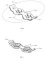
- the elongated bending sheet 100 has a larger extension along a central longitudinal axis Lc compared to a central transverse axis T C extending transverse to the central longitudinal axis L C .
- the central longitudinal axis L C for this embodiment is indicated in figure 3 .
- a point of intersection of the central longitudinal axis Lc and the central transverse axis Tc preferably defines a center C of the elongated bending sheet 100, preferably a geometric center.
- the central transverse axis Tc extends from the center C perpendicular to the drawing plane.
- the plane generated by the central longitudinal axis Lc and the central transverse axis T C is denoted as central plane C P .
- the elongated bending sheet is U-shaped when viewed in cross-section along the central transverse axis T C .
- a sensor S such as a strain gauge is arranged at or adjacent to the center C.
- a first torus 110 and a second torus 120 are rigidly mounted or connected to the elongated bending sheet 100 by means of welding, gluing or the like.
- the first torus 110 is in direct contact with the elongated bending sheet 100 at two torus sections 114. These two torus sections 114 form a first pair of bearings of the elongated bending sheet 100 for abutment at a first component 1.
- two recesses 112 are present at both sides of each torus section 114 of the first torus 110 due to the general U shape of the elongated bending sheet 100.
- the two torus sections 114 of the first torus 110 are arranged on a first side of the elongated bending sheet 100 and have a first distance along the central longitudinal axis Lc with respect to each other. With respect to figure 3 , the first torus 110 is arranged on a first side of the central plane C P .
- the respective first distance corresponds to a first diameter D a of the first torus 110.
- the two torus sections 114 as well as the complete first torus 110 generate a first supporting plane. As the side of the first torus 110 facing away from the elongated bending sheet 100 abuts in use at the first component 1, this side is used for determining the first supporting plane.
- two torus sections of the second torus 120 are in direct contact with the elongated bending sheet 100 and are arranged on an opposite second side of the elongated bending sheet 100.
- the two torus sections of the second torus 120 form a second pair of bearings.
- these second pair of bearings is arranged on a second side of the central plane C P opposite to the first side.
- the second torus 120 has a second diameter D i , defining a second distance between the two torus sections of the second torus 120 in direct contact with the elongated bending sheet 100 along the central longitudinal axis Lc. Further, the two torus sections as well as the complete second torus 120 generate a second supporting plane. As the side of the second torus 120 facing away from the elongated bending sheet 100 abuts in use at the second component 3, this side is used for determining the second supporting plane.
- all three planes i.e., the central plane C P , the first supporting plane and the second supporting plane are arranged parallel to each other in an initial or unloaded state of the elongated bending sheet 100.
- the second diameter D i is smaller than the first diameter D a . Consequently, the distance along the central longitudinal axis Lc between a bearing of the first pair of bearings and an adjacent bearing of the second pair of bearings defines a lever arm.
- the elongated bending sheet 100 is formed symmetrically along the central longitudinal axis Lc and the central transverse axis Tc. Further, it is preferred that the second distance and, thus, the second diameter D i is in the range of 30 to 90% of the first distance and, thus, of the first diameter D a .
- the central longitudinal axis Lc extends centrally through the first and the second pair of bearings, i.e., through the two tours sections 114 of the first torus 110 and the two torus sections of the second torus 120 in direct abutment with the elongated bending sheet 100.
- the central transverse axis T C extends also centrally between the two torus sections 114 of the first torus 110 and the two torus sections of the second torus 120 in direct abutment with the elongated bending sheet 100 and thus between the first and the second pair of bearings.
- the elongated bending sheet 100 having the first 110 and the second torus 120 is arranged in a vehicle, preferably a land vehicle, such as a car or truck, or an air vehicle or aircraft.
- the first component is part of a vehicle body, in particular a suspension strut bearing seat
- the second component is part of a running gear, in particular a suspension strut.
- figure 9 it is referred to the below discussion of figure 9 , in which a third embodiment of an elongated bending sheet 300 is shown in a respectively installed state.
- the elongated bending sheet 100 is arranged between the first component 1 and the second component 3 for example by clamping. Additionally, the elongated bending sheet 100 may be arranged between the first 1 and the second component 3 in a loss-proof manner. This will also be explained below.
- the first 1 and the second component 3 are movable with respect to each other.
- the reference sign L S indicates the respective movement direction and corresponds to a longitudinal axis of the suspension strut as second component.
- a deviation from a complete perpendicular movement is allowable.
- a respective deviation is less than a spherical angle of 30°, preferably 20° and more preferably 10° with respect to an axis perpendicular to the central plane C P .
- the distance therebetween is for example decreased.
- Such a decrease in the distance results in forces acting on the first 110 and second torus 120 and, thus, on the torus sections 114 of the first 110 and the second torus 120 in direct contact with the elongated bending sheet 100. Accordingly, such a relative movement causes a deformation of the elongated bending sheet 100 as it is illustrated in figure 3 .
- Figure 4 illustrates the elongated bending sheet 100 in a schematic manner for explaining the course of the deformation, in particular based on a bending moment M, and the forces acting on the elongated bending sheet 100 over the length of the bending sheet.
- the uppermost illustration of figure 4 shows a schematic elongated bending sheet 100 indicating a neutral fiber 103, a deformation based on the dashed line as well as a tension within the bending sheet 100 by the sign + and a compression within the bending sheet 100 by the sign -.
- a resulting bending moment M is indicated over a length s of the bending sheet 100. Consequently, the lowermost illustration indicates the course of a transverse force Q acting on the elongated bending sheet 100 over the length s of the elongated bending sheet 100.
- the elongated bending sheet 100 shows in an initial or unladen state of the vehicle a first deformation.
- the vehicle load capacity i.e., the load which can be added to the vehicle until the maximum load or payload is reached, is completely available.
- the second embodiment of the elongated bending sheet 200 comprises a first torus 210 and a second torus 220.
- the second embodiment 200 comprises an opening 222 in the construction surrounding the second torus 220.
- figure 5 indicates a suspension strut top mount 24 having three bolts 10 for fastening the suspension strut as second component 3 to the vehicle body, in particular the suspension strut bearing seat, as first component 1.
- the elongated bending sheet 200 is arranged or fastened between the first 1 and the second component 3 in a loss-proof manner.
- the opening 222 has the shape of an elongated hole.
- the functioning of the elongated bending sheet 200 corresponds to the functioning of the first embodiment of the elongated bending sheet 100.
- the third embodiment of an elongated bending sheet 300 does not have bearings which are part of a torus. Nevertheless, the conceptional idea is based on the first 100 and the second embodiment 200. For indicating the respective conceptual similarity, a first imaginary circle 312 and a second imaginary circle 322 is indicated in the illustrations.
- the elongated bending sheet 300 has a larger extension along a central longitudinal axis Lc compared to a central transverse axis Tc extending transverse to the central longitudinal axis Lc.
- the central longitudinal axis Lc for this embodiment is indicated in figure 9 .
- a point of intersection of the central longitudinal axis Lc and the central transverse axis T C preferably defines a center C of the elongated bending sheet 300, preferably a geometric center. Accordingly, and again with respect to figure 9 , the central transverse axis T C extends from the center C perpendicular to the drawing plane.
- central plane C P The plane generated by the central longitudinal axis Lc and the central transverse axis Tc is denoted in figure 9 as central plane C P . Further, a sensor S such as a strain gauge is arranged at or adjacent to the center C (cf. figure 9 ).
- the elongated bending sheet 300 has a first pair of bearings 310 having a first distance d 1 along the central longitudinal axis Lc with respect to each other, are arranged on a first side of the elongated bending sheet 300 and generate a first supporting plane. This first supporting plane can be concluded from the first imaginary circle 312.
- the second pair of bearings 320 comprises two bearings having as second distance d 2 along the central longitudinal axis L C with respect to each other which is smaller than the first distance d 1 .
- the bearings of the second pair 320 are arranged on a second side of the elongated bending sheet 300 opposite to the first side and generate a second supporting plane different from the first supporting plane. This second supporting plane can be concluded from the second imaginary circle 322.
- the central plane C P is arranged at the level of the middle portion or center C of the elongated bending sheet 300, the central plane C P is arranged between the first and the second supporting plane (cf. also figure 9 ).
- the bearings of the first 310 and second pair of bearings 320 extend parallel to the central transverse axis Tc. Further, the elongated bending sheet 300 is formed in one piece with the first 310 and the second integral pair of bearings 320.
- first 310 and the second pair of bearings 320 are impressed into the elongated bending sheet 300.
- the component thickness of the elongated bending sheet 300 is further generally uniformly. Accordingly, a generally curved shape connecting the first and the second supporting plane with each other results when viewing the elongated bending sheet 300 in a side view (cf. figure 9 ).
- the elongated bending sheet has a course which starts at the level of the first supporting plane, crosses the level of the central plane and arrives at the level of the second supporting plane. From here, it rises again to the central plane in the center C of the elongated bending sheet. In this portion, the sensor S is arranged. In the further course, the level of the elongated bending sheet 300 decreases from the central plane C P to the second supporting plane, rises again and crosses the central plane C P to arrive at the right side at the first supporting plane.
- the so formed elongated bending sheet 300 realizes the same technical effects as the elongated bending sheet according to the first 100 and second embodiment 200.
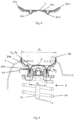
- Figure 9 shows in this regard the elongated bending sheet 300 in an assembled state between the first 1 and the second component 3.
- the first component 1 is part of a vehicle body, in particular a suspension strut bearing seat.
- the second component 3 is part of a running gear, in particular a suspension strut comprising a spring 20 and a damper 22.
- the elongated bending sheet 300 is clamped between the first 1 and the second component 3. This is performed such that a longitudinal axis Ls of the suspension strut extends preferably perpendicular to the central plane C P .
- a relative movement between the first 1 and the second component 3 occurs.
- the distance between both components 1, 3 is decreased.
- the resulting force acting on the elongated bending sheet 300 causes a deformation of the elongated bending sheet which can be measured by the sensor S arranged at or adjacent to the center C.
- the signal of the sensor S can thus be used for determining a mechanical vehicle load or, in other words, a remaining vehicle load capacity.
- remaining vehicle load capacity indicates the vehicle load which still can be added to the vehicle before reaching the allowed additional load.
- a fourth embodiment 400 of an elongated bending sheet 400 is discussed. This embodiment is similar to the third embodiment 300.
- the elongated bending sheet 400 has a generally inverted U-shape when viewed in cross-section along the central transverse axis Tc.
- the first pair of bearings 410 is arranged on a first side and the second pair of bearings 420 is arranged on a second side of the elongated bending sheet 400.
- the second pair of bearings 420 is formed by four bearing points, two on each side with respect to the central longitudinal axis Lc.
- each pair of the second pair of bearings 420 is formed by two bearings.
- the elongated bending sheet 400 has an opening 402 through which a bolt 10 can extend in use which allows the elongated bending sheet 400 to be mounted in a loss proof manner between the first 1 and the second component 3.
- the respective embodiment is shown in figure 11 .
- a recess 404 is provided in the elongated bending sheet 400 at or adjacent to the central transverse axis Tc.
- a signal of the sensor S corresponding to a deformation of the elongated bending sheet 100; 200; 300; 400 depending on the mechanical vehicle load, in particular the remaining vehicle load capacity, is determined.
- the mechanical vehicle load is determined in step ii based on the determined signal. This is performed in particular by means of a respective table or the like.
- a method for manufacturing a first alternative of an elongated bending sheet 300, 400 is shown in figure 13 .
- a sheet portion is separated from a metal sheet, in particular by means of punching.
- the sheet portion is processed, in particular by means of deep drawing, rolling or bending, such that the sheet portion comprises the features of the third or fourth embodiment of the elongated bending sheet 300; 400.
- a method for manufacturing a second alternative of an elongated bending sheet 100; 200 has as first step a providing a bending sheet 100, 200 (cf. figure 14 ).
- first step a providing a bending sheet 100, 200 (cf. figure 14 ).
- second step b two torus sections of a first torus 110, 210 or a complete first torus 110, 210 is provided
- third step c two torus sections of a second torus 120, 220 or a complete second torus 120, 220 is provided.
- These three steps may occur in any order. Thus, they may be performed subsequently or at the same time.
- the two torus sections of the first torus 110, 210 or the first torus 110, 210 are fastened in step d at the elongated bending sheet 100, 200.
- step e the two torus sections of the second torus 120, 220 or the second torus 120, 220 is fastened at the bending sheet 100, 200.
- the steps d and e can be performed in any order.
Landscapes
- Physics & Mathematics (AREA)
- General Physics & Mathematics (AREA)
- Vehicle Body Suspensions (AREA)
Claims (21)
- Tôle de flexion (300 ; 400) allongée permettant de déterminer une charge mécanique de véhicule, en particulier une capacité de charge restante de véhicule, ayant une extension supérieure le long d'un axe longitudinal central (Lc) par rapport à un axe transversal central (Tc) s'étendant transversalement à l'axe longitudinal central (Lc), dans laquelle l'axe longitudinal central (Lc) et l'axe transversal central (TC) génèrent un plan central (CP), dans laquellea. la tôle de flexion (300 ; 400) allongée est formée d'un seul tenant avec une première (310 ; 410) et une seconde paire intégrée de paliers (320 ; 420),b. les paliers de la première paire (310 ; 410) ont une première distance (d1) le long de l'axe longitudinal central (Lc) l'un par rapport à l'autre, sont agencés sur un premier côté de la tôle de flexion (300 ; 400) allongée et génèrent un premier plan de support,c. les paliers de la seconde paire (320 ; 420) ont une seconde distance (d2) le long de l'axe longitudinal central (Lc) l'un par rapport à l'autre, qui est plus petite que la première distance (d1), sont agencés sur un second côté de la tôle de flexion (300 ; 400) allongée, opposé au premier côté, et génèrent un second plan de support différent du premier plan de support etd. la tôle de flexion (300 ; 400) allongée peut être agencée entre un premier (1) et un second composant (3) qui sont mobiles l'un par rapport à l'autre, de sorte que la première paire de paliers (310 ; 410) bute au niveau du premier composant (1) et que la seconde paire de paliers (320 ; 420) bute au niveau du second composant (3), de sorte qu'un mouvement réciproque du premier (1) et du second composant (3) l'un par rapport à l'autre provoque une déformation détectable de la tôle de flexion (300 ; 400).
- Tôle de flexion (100 ; 200) allongée permettant de déterminer une charge mécanique de véhicule, en particulier une capacité de charge restante de véhicule, ayant une extension supérieure le long d'un axe longitudinal central (Lc) par rapport à un axe transversal central (Tc) s'étendant transversalement à l'axe longitudinal central (Lc), dans laquelle l'axe longitudinal central (Lc) et l'axe transversal central (TC) génèrent un plan central (CP), dans laquellea. la tôle de flexion (100 ; 200) allongée est constituée d'une première et d'une seconde paire de paliers,b. les paliers de la première paire sont formés par deux sections de tore (114) d'un premier tore (110 ; 210) avec un premier diamètre (Da) ayant une première distance le long de l'axe longitudinal central (Lc) l'un par rapport à l'autre, sont agencés sur un premier côté de la tôle de flexion (100 ; 200) allongée et génèrent un premier plan de support, etc. les paliers de la seconde paire sont formés par deux sections de tore (120 ; 220) avec un second diamètre (Di) ayant une seconde distance le long de l'axe longitudinal central (Lc) l'un par rapport à l'autre qui est inférieure à la première distance, sont agencés sur un second côté de la tôle de flexion (100 ; 200) allongée, opposé au premier côté, et génèrent un second plan de support différent du premier plan de support, etd. la tôle de flexion (100 ; 200) allongée peut être agencée entre un premier (1) et un second composant (2) qui sont mobiles l'un par rapport à l'autre, de sorte que la première paire de paliers bute au niveau du premier composant (1) et que la seconde paire de paliers bute au niveau du second composant (3), de sorte qu'un mouvement réciproque du premier (1) et du second composant (3) l'un par rapport à l'autre provoque une déformation détectable de la tôle de flexion (100 ; 200).
- Tôle de flexion (100 ; 200 ; 300 ; 400) allongée selon l'une des revendications précédentes, qui est formée symétriquement le long de l'axe longitudinal central (Lc) et/ou de l'axe transversal central (TC).
- Tôle de flexion (100 ; 200 ; 300 ; 400) allongée selon l'une des revendications précédentes, ayant un capteur (S), en particulier une jauge de contrainte, au niveau d'un point d'intersection de l'axe longitudinal central (Lc) et de l'axe transversal central (Tc) ou de manière adjacente à ceux-ci.
- Tôle de flexion (100 ; 200 ; 300 ; 400) allongée selon la revendication 4, ayant un seul capteur (S).
- Tôle de flexion (100 ; 200 ; 300 ; 400) allongée selon l'une des revendications précédentes, dans laquelle la seconde distance (d2) est située dans la plage comprise entre 30 % et 90 % de la première distance (d1).
- Tôle de flexion (100 ; 200 ; 300 ; 400) allongée selon l'une des revendications précédentes, dans laquelle l'axe longitudinal central (Lc) s'étend centralement à travers la première (310 ; 410) et la seconde paire de paliers (320 ; 420).
- Tôle de flexion (100 ; 200 ; 300 ; 400) allongée selon l'une des revendications précédentes, dans laquelle l'axe transversal central (Tc) s'étend centralement entre la première (310 ; 410) et la seconde paire de paliers (320 ; 420).
- Tôle de flexion (300 ; 400) allongée selon l'une des revendications précédentes en combinaison avec la revendication 1, ayant au plus une ouverture (222 ; 422) sous la forme d'un trou allongé.
- Tôle de flexion (300 ; 400) allongée selon l'une des revendications précédentes en combinaison avec la revendication 1, ayant une forme généralement incurvée reliant le premier et le second plan de support l'un à l'autre.
- Tôle de flexion (300 ; 400) allongée selon l'une des revendications précédentes en combinaison avec la revendication 1, dont l'épaisseur des composants est généralement uniforme.
- Tôle de flexion (300 ; 400) allongée selon l'une des revendications précédentes en combinaison avec la revendication 1, dans laquelle la première (310 ; 410) et/ou la seconde paire de paliers (320 ; 420) est imprimée dans la tôle de flexion (300 ; 400) allongée.
- Tôle de flexion (100 ; 200) allongée selon l'une des revendications précédentes en combinaison avec la revendication 2, dans laquelle la première paire de paliers est formée par le premier tore complet (110 ; 210) et/ou la seconde paire de paliers est formée par le second tore complet (120 ; 220).
- Tôle de flexion (100 ; 200) allongée selon l'une des revendications précédentes en combinaison avec la revendication 2, dans laquelle la première et la seconde paire de paliers sont reliées fermement à la tôle de flexion (100 ; 200) allongée au moyen d'une soudure, d'un collage ou analogue.
- Véhicule, de préférence véhicule terrestre ou véhicule aérien ou aéronef, comportant une tôle de flexion (100 ; 200 ; 300 ; 400) allongée selon l'une des revendications 1 à 14.
- Véhicule selon la revendication 15, dans lequel le premier composant (1) fait partie d'une carrosserie de véhicule, en particulier un siège de palier de jambe de suspension, et le second composant (3) fait partie d'un train de roues, en particulier une jambe de suspension.
- Véhicule selon la revendication 15 ou 16, dans lequel le véhicule est une voiture ou un camion.
- Véhicule selon la revendication 16 ou 17, dans lequel, au niveau de chaque liaison entre la carrosserie de véhicule et le train de roues ou de manière adjacente à celle-ci, une tôle de flexion (100 ; 200 ; 300 ; 400) respective est fournie.
- Procédé de détermination d'une charge mécanique de véhicule, en particulier d'une capacité de charge restante de véhicule, utilisant une tôle de flexion (100 ; 200 ; 300 ; 400) allongée selon l'une des revendications 1 à 14 et au moins un capteur (S), en particulier une jauge de contrainte, comportant les étapes de :a. détermination (i) d'un signal du capteur (S) correspondant à une déformation de la tôle de flexion (100 ; 200 ; 300 ; 400) allongée selon la charge mécanique de véhicule, en particulier la capacité de charge restante de véhicule,b. détermination (ii) de la charge mécanique de véhicule, en particulier de la capacité de charge restante de véhicule, sur la base du signal déterminé, en particulier au moyen d'une table respective ou analogue.
- Procédé de fabrication d'une tôle de flexion (300 ; 400) allongée selon la revendication 1, comportant les étapes de :a. séparation (A) d'une portion de tôle à partir d'une tôle métallique, en particulier au moyen d'un poinçonnage,b. traitement (B) de la portion de tôle, en particulier par emboutissage, roulage ou flexion, de sorte que la portion de tôle comporte les caractéristiques d'une tôle de flexion (300 ; 400) allongée selon la revendication 1.
- Procédé de fabrication d'une tôle de flexion (100 ; 200) allongée selon la revendication 2, comportant les étapes de :a. fourniture (a) d'une tôle de flexion (100 ; 200),b. fourniture (b) de deux sections de tore (114) d'un premier tore (110 ; 210) ou d'un premier tore complet (110 ; 210),c. fourniture (c) de deux sections de tore d'un second tore (120 ; 220) ou d'un second tore complet (120 ; 220),d. serrage (d) des deux sections de tore (114) du premier tore (110 ; 210) ou du premier tore (110 ; 210) au niveau de la tôle de flexion ete. serrage (e) des deux sections de tore du second tore (120 ; 220) ou du second tore (120 ; 220) au niveau de la tôle de flexion (100 ; 200).
Priority Applications (1)
| Application Number | Priority Date | Filing Date | Title |
|---|---|---|---|
| EP22305418.0A EP4253921B1 (fr) | 2022-03-31 | 2022-03-31 | Tôle de flexion allongée pour déterminer une charge mécanique de véhicule et un véhicule respectif |
Applications Claiming Priority (1)
| Application Number | Priority Date | Filing Date | Title |
|---|---|---|---|
| EP22305418.0A EP4253921B1 (fr) | 2022-03-31 | 2022-03-31 | Tôle de flexion allongée pour déterminer une charge mécanique de véhicule et un véhicule respectif |
Publications (2)
| Publication Number | Publication Date |
|---|---|
| EP4253921A1 EP4253921A1 (fr) | 2023-10-04 |
| EP4253921B1 true EP4253921B1 (fr) | 2024-08-07 |
Family
ID=81308010
Family Applications (1)
| Application Number | Title | Priority Date | Filing Date |
|---|---|---|---|
| EP22305418.0A Active EP4253921B1 (fr) | 2022-03-31 | 2022-03-31 | Tôle de flexion allongée pour déterminer une charge mécanique de véhicule et un véhicule respectif |
Country Status (1)
| Country | Link |
|---|---|
| EP (1) | EP4253921B1 (fr) |
Family Cites Families (3)
| Publication number | Priority date | Publication date | Assignee | Title |
|---|---|---|---|---|
| US3743041A (en) | 1972-09-22 | 1973-07-03 | J Videon | Transducer beam assembly |
| DE102005005354A1 (de) * | 2005-02-05 | 2006-08-10 | Bosch Rexroth Aktiengesellschaft | Kraftmessvorrichtung und Dehnungsmesselement |
| DE102018221808A1 (de) * | 2018-12-14 | 2020-06-18 | Continental Automotive Gmbh | Anordnung zum Bestimmen der Durchbiegung eines Bauteils und Verfahren zum Herstellen einer solchen Anordnung |
-
2022
- 2022-03-31 EP EP22305418.0A patent/EP4253921B1/fr active Active
Also Published As
| Publication number | Publication date |
|---|---|
| EP4253921A1 (fr) | 2023-10-04 |
Similar Documents
| Publication | Publication Date | Title |
|---|---|---|
| EP2809532B1 (fr) | Suspension de véhicule comprenant un ensemble ressort à lames léger | |
| US20160152106A1 (en) | Vehicle suspension and leaf spring therefore | |
| US4800751A (en) | System for detecting load applied to suspension | |
| RU2517274C2 (ru) | Независимая подвеска транспортного средства | |
| CN105026190B (zh) | 多次渐缩的悬架部件 | |
| US7246807B2 (en) | Vibration damping device for use in automotive suspension system and suspension system using the same | |
| US20030006574A1 (en) | Input separation type strut suspension device | |
| CN113232469B (zh) | 一种前悬架系统及车辆 | |
| US20040017104A1 (en) | Outboard ribbed wheel hub | |
| US6196563B1 (en) | Reversible high ground clearance steering axle | |
| US7744103B2 (en) | Hollow shaft junction connection | |
| MXPA05012265A (es) | Sistema de suspension, con bajo contenido de piezas, ligero en cuanto a peso para vehiculos con ruedas. | |
| US5755456A (en) | Spring support for vehicle swing half-axles | |
| US20200223272A1 (en) | Structural member and manufacturing method of the structural member | |
| EP4253921B1 (fr) | Tôle de flexion allongée pour déterminer une charge mécanique de véhicule et un véhicule respectif | |
| US7353697B2 (en) | System for mounting an engine to a frame | |
| CN106042812B (zh) | 一种双驱动桥空气悬架总成 | |
| US11247262B2 (en) | Vehicle knuckle | |
| JP2001343277A (ja) | 車両用荷重測定装置 | |
| CN113459724A (zh) | 立柱 | |
| US4106789A (en) | Motor vehicle suspension system | |
| US11607921B2 (en) | Bushing | |
| CN220884548U (zh) | 车辆的车架和车辆 | |
| CN110997365B (zh) | 用于制造具有横向引导连杆的机动车辆横梁的方法 | |
| JPH0632780U (ja) | 油圧緩衝器の荷重検出構造 |
Legal Events
| Date | Code | Title | Description |
|---|---|---|---|
| PUAI | Public reference made under article 153(3) epc to a published international application that has entered the european phase |
Free format text: ORIGINAL CODE: 0009012 |
|
| STAA | Information on the status of an ep patent application or granted ep patent |
Free format text: STATUS: REQUEST FOR EXAMINATION WAS MADE |
|
| 17P | Request for examination filed |
Effective date: 20230313 |
|
| AK | Designated contracting states |
Kind code of ref document: A1 Designated state(s): AL AT BE BG CH CY CZ DE DK EE ES FI FR GB GR HR HU IE IS IT LI LT LU LV MC MK MT NL NO PL PT RO RS SE SI SK SM TR |
|
| GRAP | Despatch of communication of intention to grant a patent |
Free format text: ORIGINAL CODE: EPIDOSNIGR1 |
|
| STAA | Information on the status of an ep patent application or granted ep patent |
Free format text: STATUS: GRANT OF PATENT IS INTENDED |
|
| INTG | Intention to grant announced |
Effective date: 20240311 |
|
| GRAS | Grant fee paid |
Free format text: ORIGINAL CODE: EPIDOSNIGR3 |
|
| GRAA | (expected) grant |
Free format text: ORIGINAL CODE: 0009210 |
|
| STAA | Information on the status of an ep patent application or granted ep patent |
Free format text: STATUS: THE PATENT HAS BEEN GRANTED |
|
| AK | Designated contracting states |
Kind code of ref document: B1 Designated state(s): AL AT BE BG CH CY CZ DE DK EE ES FI FR GB GR HR HU IE IS IT LI LT LU LV MC MK MT NL NO PL PT RO RS SE SI SK SM TR |
|
| REG | Reference to a national code |
Ref country code: GB Ref legal event code: FG4D |
|
| REG | Reference to a national code |
Ref country code: CH Ref legal event code: EP |
|
| REG | Reference to a national code |
Ref country code: IE Ref legal event code: FG4D |
|
| REG | Reference to a national code |
Ref country code: DE Ref legal event code: R096 Ref document number: 602022005180 Country of ref document: DE |
|
| REG | Reference to a national code |
Ref country code: LT Ref legal event code: MG9D |
|
| REG | Reference to a national code |
Ref country code: NL Ref legal event code: MP Effective date: 20240807 |
|
| PG25 | Lapsed in a contracting state [announced via postgrant information from national office to epo] |
Ref country code: NO Free format text: LAPSE BECAUSE OF FAILURE TO SUBMIT A TRANSLATION OF THE DESCRIPTION OR TO PAY THE FEE WITHIN THE PRESCRIBED TIME-LIMIT Effective date: 20241107 |
|
| REG | Reference to a national code |
Ref country code: AT Ref legal event code: MK05 Ref document number: 1711432 Country of ref document: AT Kind code of ref document: T Effective date: 20240807 |
|
| PG25 | Lapsed in a contracting state [announced via postgrant information from national office to epo] |
Ref country code: FI Free format text: LAPSE BECAUSE OF FAILURE TO SUBMIT A TRANSLATION OF THE DESCRIPTION OR TO PAY THE FEE WITHIN THE PRESCRIBED TIME-LIMIT Effective date: 20240807 Ref country code: PL Free format text: LAPSE BECAUSE OF FAILURE TO SUBMIT A TRANSLATION OF THE DESCRIPTION OR TO PAY THE FEE WITHIN THE PRESCRIBED TIME-LIMIT Effective date: 20240807 Ref country code: NL Free format text: LAPSE BECAUSE OF FAILURE TO SUBMIT A TRANSLATION OF THE DESCRIPTION OR TO PAY THE FEE WITHIN THE PRESCRIBED TIME-LIMIT Effective date: 20240807 Ref country code: PT Free format text: LAPSE BECAUSE OF FAILURE TO SUBMIT A TRANSLATION OF THE DESCRIPTION OR TO PAY THE FEE WITHIN THE PRESCRIBED TIME-LIMIT Effective date: 20241209 Ref country code: GR Free format text: LAPSE BECAUSE OF FAILURE TO SUBMIT A TRANSLATION OF THE DESCRIPTION OR TO PAY THE FEE WITHIN THE PRESCRIBED TIME-LIMIT Effective date: 20241108 |
|
| PG25 | Lapsed in a contracting state [announced via postgrant information from national office to epo] |
Ref country code: BG Free format text: LAPSE BECAUSE OF FAILURE TO SUBMIT A TRANSLATION OF THE DESCRIPTION OR TO PAY THE FEE WITHIN THE PRESCRIBED TIME-LIMIT Effective date: 20240807 |
|
| PG25 | Lapsed in a contracting state [announced via postgrant information from national office to epo] |
Ref country code: LV Free format text: LAPSE BECAUSE OF FAILURE TO SUBMIT A TRANSLATION OF THE DESCRIPTION OR TO PAY THE FEE WITHIN THE PRESCRIBED TIME-LIMIT Effective date: 20240807 |
|
| PG25 | Lapsed in a contracting state [announced via postgrant information from national office to epo] |
Ref country code: AT Free format text: LAPSE BECAUSE OF FAILURE TO SUBMIT A TRANSLATION OF THE DESCRIPTION OR TO PAY THE FEE WITHIN THE PRESCRIBED TIME-LIMIT Effective date: 20240807 Ref country code: IS Free format text: LAPSE BECAUSE OF FAILURE TO SUBMIT A TRANSLATION OF THE DESCRIPTION OR TO PAY THE FEE WITHIN THE PRESCRIBED TIME-LIMIT Effective date: 20241207 |
|
| PG25 | Lapsed in a contracting state [announced via postgrant information from national office to epo] |
Ref country code: HR Free format text: LAPSE BECAUSE OF FAILURE TO SUBMIT A TRANSLATION OF THE DESCRIPTION OR TO PAY THE FEE WITHIN THE PRESCRIBED TIME-LIMIT Effective date: 20240807 |
|
| PG25 | Lapsed in a contracting state [announced via postgrant information from national office to epo] |
Ref country code: RS Free format text: LAPSE BECAUSE OF FAILURE TO SUBMIT A TRANSLATION OF THE DESCRIPTION OR TO PAY THE FEE WITHIN THE PRESCRIBED TIME-LIMIT Effective date: 20241107 Ref country code: ES Free format text: LAPSE BECAUSE OF FAILURE TO SUBMIT A TRANSLATION OF THE DESCRIPTION OR TO PAY THE FEE WITHIN THE PRESCRIBED TIME-LIMIT Effective date: 20240807 |
|
| PG25 | Lapsed in a contracting state [announced via postgrant information from national office to epo] |
Ref country code: RS Free format text: LAPSE BECAUSE OF FAILURE TO SUBMIT A TRANSLATION OF THE DESCRIPTION OR TO PAY THE FEE WITHIN THE PRESCRIBED TIME-LIMIT Effective date: 20241107 Ref country code: PT Free format text: LAPSE BECAUSE OF FAILURE TO SUBMIT A TRANSLATION OF THE DESCRIPTION OR TO PAY THE FEE WITHIN THE PRESCRIBED TIME-LIMIT Effective date: 20241209 Ref country code: PL Free format text: LAPSE BECAUSE OF FAILURE TO SUBMIT A TRANSLATION OF THE DESCRIPTION OR TO PAY THE FEE WITHIN THE PRESCRIBED TIME-LIMIT Effective date: 20240807 Ref country code: NO Free format text: LAPSE BECAUSE OF FAILURE TO SUBMIT A TRANSLATION OF THE DESCRIPTION OR TO PAY THE FEE WITHIN THE PRESCRIBED TIME-LIMIT Effective date: 20241107 Ref country code: NL Free format text: LAPSE BECAUSE OF FAILURE TO SUBMIT A TRANSLATION OF THE DESCRIPTION OR TO PAY THE FEE WITHIN THE PRESCRIBED TIME-LIMIT Effective date: 20240807 Ref country code: LV Free format text: LAPSE BECAUSE OF FAILURE TO SUBMIT A TRANSLATION OF THE DESCRIPTION OR TO PAY THE FEE WITHIN THE PRESCRIBED TIME-LIMIT Effective date: 20240807 Ref country code: IS Free format text: LAPSE BECAUSE OF FAILURE TO SUBMIT A TRANSLATION OF THE DESCRIPTION OR TO PAY THE FEE WITHIN THE PRESCRIBED TIME-LIMIT Effective date: 20241207 Ref country code: HR Free format text: LAPSE BECAUSE OF FAILURE TO SUBMIT A TRANSLATION OF THE DESCRIPTION OR TO PAY THE FEE WITHIN THE PRESCRIBED TIME-LIMIT Effective date: 20240807 Ref country code: GR Free format text: LAPSE BECAUSE OF FAILURE TO SUBMIT A TRANSLATION OF THE DESCRIPTION OR TO PAY THE FEE WITHIN THE PRESCRIBED TIME-LIMIT Effective date: 20241108 Ref country code: FI Free format text: LAPSE BECAUSE OF FAILURE TO SUBMIT A TRANSLATION OF THE DESCRIPTION OR TO PAY THE FEE WITHIN THE PRESCRIBED TIME-LIMIT Effective date: 20240807 Ref country code: ES Free format text: LAPSE BECAUSE OF FAILURE TO SUBMIT A TRANSLATION OF THE DESCRIPTION OR TO PAY THE FEE WITHIN THE PRESCRIBED TIME-LIMIT Effective date: 20240807 Ref country code: BG Free format text: LAPSE BECAUSE OF FAILURE TO SUBMIT A TRANSLATION OF THE DESCRIPTION OR TO PAY THE FEE WITHIN THE PRESCRIBED TIME-LIMIT Effective date: 20240807 Ref country code: AT Free format text: LAPSE BECAUSE OF FAILURE TO SUBMIT A TRANSLATION OF THE DESCRIPTION OR TO PAY THE FEE WITHIN THE PRESCRIBED TIME-LIMIT Effective date: 20240807 |
|
| PG25 | Lapsed in a contracting state [announced via postgrant information from national office to epo] |
Ref country code: DK Free format text: LAPSE BECAUSE OF FAILURE TO SUBMIT A TRANSLATION OF THE DESCRIPTION OR TO PAY THE FEE WITHIN THE PRESCRIBED TIME-LIMIT Effective date: 20240807 Ref country code: SM Free format text: LAPSE BECAUSE OF FAILURE TO SUBMIT A TRANSLATION OF THE DESCRIPTION OR TO PAY THE FEE WITHIN THE PRESCRIBED TIME-LIMIT Effective date: 20240807 |
|
| PG25 | Lapsed in a contracting state [announced via postgrant information from national office to epo] |
Ref country code: EE Free format text: LAPSE BECAUSE OF FAILURE TO SUBMIT A TRANSLATION OF THE DESCRIPTION OR TO PAY THE FEE WITHIN THE PRESCRIBED TIME-LIMIT Effective date: 20240807 |
|
| PG25 | Lapsed in a contracting state [announced via postgrant information from national office to epo] |
Ref country code: CZ Free format text: LAPSE BECAUSE OF FAILURE TO SUBMIT A TRANSLATION OF THE DESCRIPTION OR TO PAY THE FEE WITHIN THE PRESCRIBED TIME-LIMIT Effective date: 20240807 |
|
| PG25 | Lapsed in a contracting state [announced via postgrant information from national office to epo] |
Ref country code: SK Free format text: LAPSE BECAUSE OF FAILURE TO SUBMIT A TRANSLATION OF THE DESCRIPTION OR TO PAY THE FEE WITHIN THE PRESCRIBED TIME-LIMIT Effective date: 20240807 |
|
| REG | Reference to a national code |
Ref country code: DE Ref legal event code: R097 Ref document number: 602022005180 Country of ref document: DE |
|
| PLBE | No opposition filed within time limit |
Free format text: ORIGINAL CODE: 0009261 |
|
| STAA | Information on the status of an ep patent application or granted ep patent |
Free format text: STATUS: NO OPPOSITION FILED WITHIN TIME LIMIT |
|
| PGFP | Annual fee paid to national office [announced via postgrant information from national office to epo] |
Ref country code: DE Payment date: 20250528 Year of fee payment: 4 |
|
| 26N | No opposition filed |
Effective date: 20250508 |
|
| PG25 | Lapsed in a contracting state [announced via postgrant information from national office to epo] |
Ref country code: SE Free format text: LAPSE BECAUSE OF FAILURE TO SUBMIT A TRANSLATION OF THE DESCRIPTION OR TO PAY THE FEE WITHIN THE PRESCRIBED TIME-LIMIT Effective date: 20240807 |
|
| PG25 | Lapsed in a contracting state [announced via postgrant information from national office to epo] |
Ref country code: MC Free format text: LAPSE BECAUSE OF FAILURE TO SUBMIT A TRANSLATION OF THE DESCRIPTION OR TO PAY THE FEE WITHIN THE PRESCRIBED TIME-LIMIT Effective date: 20240807 |
|
| REG | Reference to a national code |
Ref country code: CH Ref legal event code: H13 Free format text: ST27 STATUS EVENT CODE: U-0-0-H10-H13 (AS PROVIDED BY THE NATIONAL OFFICE) Effective date: 20251024 |
|
| PG25 | Lapsed in a contracting state [announced via postgrant information from national office to epo] |
Ref country code: LU Free format text: LAPSE BECAUSE OF NON-PAYMENT OF DUE FEES Effective date: 20250331 |
|
| REG | Reference to a national code |
Ref country code: BE Ref legal event code: MM Effective date: 20250331 |
|
| PG25 | Lapsed in a contracting state [announced via postgrant information from national office to epo] |
Ref country code: BE Free format text: LAPSE BECAUSE OF NON-PAYMENT OF DUE FEES Effective date: 20250331 |
|
| PG25 | Lapsed in a contracting state [announced via postgrant information from national office to epo] |
Ref country code: CH Free format text: LAPSE BECAUSE OF NON-PAYMENT OF DUE FEES Effective date: 20250331 |
|
| PG25 | Lapsed in a contracting state [announced via postgrant information from national office to epo] |
Ref country code: IE Free format text: LAPSE BECAUSE OF NON-PAYMENT OF DUE FEES Effective date: 20250331 |
|
| PG25 | Lapsed in a contracting state [announced via postgrant information from national office to epo] |
Ref country code: IT Free format text: LAPSE BECAUSE OF FAILURE TO SUBMIT A TRANSLATION OF THE DESCRIPTION OR TO PAY THE FEE WITHIN THE PRESCRIBED TIME-LIMIT Effective date: 20240807 |
|
| PGFP | Annual fee paid to national office [announced via postgrant information from national office to epo] |
Ref country code: GB Payment date: 20260324 Year of fee payment: 5 |
|
| PG25 | Lapsed in a contracting state [announced via postgrant information from national office to epo] |
Ref country code: RO Free format text: LAPSE BECAUSE OF FAILURE TO SUBMIT A TRANSLATION OF THE DESCRIPTION OR TO PAY THE FEE WITHIN THE PRESCRIBED TIME-LIMIT Effective date: 20240807 |
|
| PGFP | Annual fee paid to national office [announced via postgrant information from national office to epo] |
Ref country code: FR Payment date: 20260324 Year of fee payment: 5 |