EP4254353A1 - Procédé d'interaction à réalité augmentée et dispositif électronique - Google Patents
Procédé d'interaction à réalité augmentée et dispositif électronique Download PDFInfo
- Publication number
- EP4254353A1 EP4254353A1 EP21914061.3A EP21914061A EP4254353A1 EP 4254353 A1 EP4254353 A1 EP 4254353A1 EP 21914061 A EP21914061 A EP 21914061A EP 4254353 A1 EP4254353 A1 EP 4254353A1
- Authority
- EP
- European Patent Office
- Prior art keywords
- real
- virtual object
- pose information
- electronic device
- location
- Prior art date
- Legal status (The legal status is an assumption and is not a legal conclusion. Google has not performed a legal analysis and makes no representation as to the accuracy of the status listed.)
- Granted
Links
Images







Classifications
-
- G—PHYSICS
- G06—COMPUTING OR CALCULATING; COUNTING
- G06T—IMAGE DATA PROCESSING OR GENERATION, IN GENERAL
- G06T19/00—Manipulating three-dimensional [3D] models or images for computer graphics
- G06T19/006—Mixed reality
-
- H—ELECTRICITY
- H04—ELECTRIC COMMUNICATION TECHNIQUE
- H04S—STEREOPHONIC SYSTEMS
- H04S7/00—Indicating arrangements; Control arrangements, e.g. balance control
- H04S7/30—Control circuits for electronic adaptation of the sound field
- H04S7/302—Electronic adaptation of stereophonic sound system to listener position or orientation
-
- G—PHYSICS
- G06—COMPUTING OR CALCULATING; COUNTING
- G06T—IMAGE DATA PROCESSING OR GENERATION, IN GENERAL
- G06T19/00—Manipulating three-dimensional [3D] models or images for computer graphics
-
- G—PHYSICS
- G06—COMPUTING OR CALCULATING; COUNTING
- G06F—ELECTRIC DIGITAL DATA PROCESSING
- G06F3/00—Input arrangements for transferring data to be processed into a form capable of being handled by the computer; Output arrangements for transferring data from processing unit to output unit, e.g. interface arrangements
- G06F3/01—Input arrangements or combined input and output arrangements for interaction between user and computer
- G06F3/011—Arrangements for interaction with the human body, e.g. for user immersion in virtual reality
-
- G—PHYSICS
- G06—COMPUTING OR CALCULATING; COUNTING
- G06F—ELECTRIC DIGITAL DATA PROCESSING
- G06F3/00—Input arrangements for transferring data to be processed into a form capable of being handled by the computer; Output arrangements for transferring data from processing unit to output unit, e.g. interface arrangements
- G06F3/01—Input arrangements or combined input and output arrangements for interaction between user and computer
- G06F3/011—Arrangements for interaction with the human body, e.g. for user immersion in virtual reality
- G06F3/012—Head tracking input arrangements
-
- G—PHYSICS
- G06—COMPUTING OR CALCULATING; COUNTING
- G06F—ELECTRIC DIGITAL DATA PROCESSING
- G06F3/00—Input arrangements for transferring data to be processed into a form capable of being handled by the computer; Output arrangements for transferring data from processing unit to output unit, e.g. interface arrangements
- G06F3/01—Input arrangements or combined input and output arrangements for interaction between user and computer
- G06F3/03—Arrangements for converting the position or the displacement of a member into a coded form
- G06F3/0304—Detection arrangements using opto-electronic means
-
- G—PHYSICS
- G06—COMPUTING OR CALCULATING; COUNTING
- G06F—ELECTRIC DIGITAL DATA PROCESSING
- G06F3/00—Input arrangements for transferring data to be processed into a form capable of being handled by the computer; Output arrangements for transferring data from processing unit to output unit, e.g. interface arrangements
- G06F3/16—Sound input; Sound output
- G06F3/167—Audio in a user interface, e.g. using voice commands for navigating, audio feedback
-
- G—PHYSICS
- G06—COMPUTING OR CALCULATING; COUNTING
- G06T—IMAGE DATA PROCESSING OR GENERATION, IN GENERAL
- G06T11/00—Two-dimensional [2D] image generation
-
- G—PHYSICS
- G06—COMPUTING OR CALCULATING; COUNTING
- G06T—IMAGE DATA PROCESSING OR GENERATION, IN GENERAL
- G06T7/00—Image analysis
- G06T7/70—Determining position or orientation of objects or cameras
- G06T7/73—Determining position or orientation of objects or cameras using feature-based methods
-
- H—ELECTRICITY
- H04—ELECTRIC COMMUNICATION TECHNIQUE
- H04S—STEREOPHONIC SYSTEMS
- H04S7/00—Indicating arrangements; Control arrangements, e.g. balance control
- H04S7/30—Control circuits for electronic adaptation of the sound field
- H04S7/302—Electronic adaptation of stereophonic sound system to listener position or orientation
- H04S7/303—Tracking of listener position or orientation
- H04S7/304—For headphones
-
- G—PHYSICS
- G06—COMPUTING OR CALCULATING; COUNTING
- G06F—ELECTRIC DIGITAL DATA PROCESSING
- G06F3/00—Input arrangements for transferring data to be processed into a form capable of being handled by the computer; Output arrangements for transferring data from processing unit to output unit, e.g. interface arrangements
- G06F3/16—Sound input; Sound output
- G06F3/165—Management of the audio stream, e.g. setting of volume, audio stream path
-
- H—ELECTRICITY
- H04—ELECTRIC COMMUNICATION TECHNIQUE
- H04S—STEREOPHONIC SYSTEMS
- H04S2400/00—Details of stereophonic systems covered by H04S but not provided for in its groups
- H04S2400/11—Positioning of individual sound objects, e.g. moving airplane, within a sound field
-
- H—ELECTRICITY
- H04—ELECTRIC COMMUNICATION TECHNIQUE
- H04S—STEREOPHONIC SYSTEMS
- H04S7/00—Indicating arrangements; Control arrangements, e.g. balance control
- H04S7/30—Control circuits for electronic adaptation of the sound field
- H04S7/302—Electronic adaptation of stereophonic sound system to listener position or orientation
- H04S7/303—Tracking of listener position or orientation
Definitions
- This application relates to the field of terminal technologies, and in particular, to an augmented reality (augmented reality, AR) interaction method and an electronic device.
- augmented reality augmented reality, AR
- An AR technology can integrate a virtual world with a real world, but how to improve authenticity of a virtual object is seldom concerned. Consequently, authenticity of a virtual role generated by using the AR technology is not high, resulting in poor user experience.
- This application provides an AR interaction method and an electronic device, to improve authenticity of a virtual object and improve user experience.
- an embodiment of this application provides an AR interaction method.
- the method includes the following steps.
- An electronic device determines pose information of a real object and/or a location of a real sound source in a real scenario, and the pose information of the real object represents a location and posture of the real object. Then, the electronic device determines pose information of a virtual object based on the pose information of the real object and/or the location of the real sound source, and the pose information of the virtual object represents a location and posture of the virtual object. Finally, the electronic device generates, based on the pose information of the virtual object, an AR image including the virtual object; and displays the AR image; and/or the electronic device generates three-dimensional 3D audio data of the virtual object based on the pose information of the real object and the pose information of the virtual object; and plays the 3D audio data.
- the virtual object may perceive a pose of the real object and the location of the real sound source, and make a corresponding action response or sound response based on the foregoing information, so that the virtual object may be the same as the real object. Therefore, in this method, virtual-real interaction that combines visual and auditory perceptions of the virtual object and the real object is implemented. This can improve an intelligent level of the virtual object, and further improves experience of virtual interaction.
- the electronic device may further establish a world coordinate system that uses the electronic device as an origin of coordinates.
- the pose information of the real object specifically represents the location and posture of the real object in the world coordinate system
- the location of the real sound source is the location of the real sound source in the world coordinate system
- the pose information of the virtual object specifically represents the location and posture of the virtual object in the world coordinate system.
- the electronic device may establish, by performing the following steps, the world coordinate system that uses the electronic device as the origin of coordinates.
- the electronic device obtains a first real-scenario image captured by a camera, and obtains posture information of the electronic device measured by an inertial measurement unit.
- the electronic device establishes the world coordinate system based on the first real-scenario image and the posture information of the electronic device according to a specified coordinate system construction algorithm (for example, a simultaneous localization and mapping (simultaneous localization and mapping, SLAM) algorithm).
- a specified coordinate system construction algorithm for example, a simultaneous localization and mapping (simultaneous localization and mapping, SLAM) algorithm.
- the electronic device may determine the pose information of the real object in the real scenario by performing the following steps.
- the electronic device obtains a second real-scenario image captured by the camera, and recognizes a key portion of a real object in the second real-scenario image. Then, the electronic device determines pose information of the key portion (for example, a head) of the real object in the second real-scenario image by using a simultaneous localization and mapping SLAM point cloud collision detection technology. Finally, the electronic device uses the pose information of the key portion of the real object as the pose information of the real object.
- the electronic device may use the pose information of the key portion of the real object as the pose information of the real object.
- the electronic device may determine the location of the real sound source in the real scenario by performing the following steps.
- the electronic device obtains real-scenario sound information collected by a microphone, and determines a location relationship between the real sound source and the microphone through sound source positioning. Then, the electronic device determines the location of the real sound source in the real scenario based on the location relationship between the real sound source and the microphone. For example, the location of the real sound source in the world coordinate system is determined based on the location relationship between the real sound source and the microphone.
- the electronic device may determine the pose information of the virtual object based on the pose information of the real object and/or the location of the real sound source, and at least one of the following: an action of the real object recognized based on the pose information of the real object, a sound instruction sent by the real sound source, an image model, an action feature, and an action response package in a virtual object model corresponding to the virtual object, and a touch operation performed by a user on the virtual object by using a display.
- the pose information of the real object that is determined by the electronic device may be considered as pose information of the real object that is seen by the virtual object, and the location of the real sound source may be considered as a location of the real sound source that is heard by the virtual object.
- the electronic device may determine the location of the virtual object based on the pose of the real object and the location of the real sound source that are perceived by the virtual object, so that the virtual object may make a corresponding action response based on the perceived pose of the real object and the perceive location of the real sound source. In this way, the virtual object may be the same as the real object.
- the electronic device may further consider another factor, to improve flexibility of determining the pose information of the virtual object.
- the electronic device may generate, by performing the following steps, the 3D audio data of the virtual object based on the pose information of the real object and the pose information of the virtual object.
- the electronic device separately determines distances between two ears of the virtual object and two ears of the real object based on the pose information of the real object and the pose information of the virtual object. Then, the electronic device calculates a volume difference and a time difference between the two ears of the real object based on the distances between the two ears of the virtual object and the two ears of the real object. Finally, the electronic device generates the 3D audio data based on the volume difference and the time difference of the real object and original sound data of the virtual object.
- the electronic device may generate the 3D audio data based on the volume difference and the time difference of the real object, to improve authenticity of playing a 3D sound emitted by the 3D audio data.
- the original sound data is set, or is determined based on at least one of the following: location and posture information of the real object, the pose information of the virtual object, the action of the real object recognized based on the pose information of the real object, the sound instruction sent by the real sound source, the image model, the action feature, and the action response package in the virtual object model corresponding to the virtual object, and the touch operation performed by the user on the virtual object by using the display.
- the electronic device may further filter the 3D audio data based on the pose information of the real object, so that reflections and refractions of the 3D audio data in a transmission process may be simulated, to make a 3D sound heard by the real object more authentic.
- an embodiment of this application further provides an electronic device, including units or modules configured to perform the steps in the first aspect.
- this application provides an electronic device, including at least one processing element and at least one storage element.
- the at least one storage element is configured to store a program and data
- the at least one processing element is configured to execute the program stored in the memory, so that the designs provided in the first aspect of this application can be implemented.
- the electronic device may further include components such as a display, a camera, and an audio circuit.
- an embodiment of this application further provides a computer storage medium.
- the storage medium stores a software program.
- the software program is read and executed by one or more processors, the method provided in the design in the first aspect may be implemented.
- an embodiment of this application further provides a computer program including instructions.
- the instructions When the instructions are run on a computer, the computer is enabled to perform the method provided in the designs in the first aspect.
- an embodiment of this application further provides a chip system.
- the chip system includes a processor, configured to support an electronic device in implementing functions in the designs in the first aspect.
- the chip system further includes a memory.
- the memory is configured to store program instructions and data that are necessary for the electronic device.
- the chip system may include a chip, or may include a chip and another discrete component.
- This application provides an AR interaction method and an electronic device, to improve authenticity of a virtual object and improve user experience.
- the method and the electronic device are based on a same technical concept. Because the method and the electronic device have similar principles for resolving a problem, reference may be mutually made to implementations of the electronic device and the method. Repeated parts are not described again.
- An AR technology is to use a computer to generate a realistic virtual world (virtual environment), so that a user can be immersed in the virtual world, to implement natural interaction between the user and the virtual world.
- the AR technology mainly focuses on how to improve integration of the virtual world and a real world, but lacks attention to improving authenticity of a virtual object in the virtual world.
- the first real object when a first real object sees or hears a second real object, the first real object may directly make a corresponding response (an action response and/or a sound response).
- the second real object can make an action response and/or a sound response
- the second real object may also make an action response and/or a sound response based on the action response and/or the sound response of the first real object.
- the virtual object may implement the foregoing audio-visual interaction with the real object like the real object, as shown in FIG. 1 .
- the real object cannot only see and hear the virtual object, but also the virtual object can see and/or hear the real object, and can make some corresponding action responses and/or sound responses, so that the real object or a user can perceive that the virtual object has an audio-visual function.
- the virtual object can see and/or hear the real object like the real object, and make some corresponding action responses and/or sound responses, so that the authenticity of the virtual object can be improved, and the user can be immersed in the virtual world, to finally improve user experience.
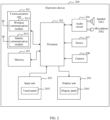
- FIG. 2 shows a possible structure of the electronic device.
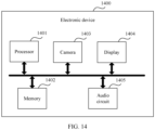
- an electronic device 200 includes components such as a communication unit 201, a processor 202, a memory 203, a display unit 204, an input unit 205, an audio circuit 206, a sensor 207, and a camera 208.
- the communication unit 201 is configured to: implement a function of the electronic device 200, and implement data communication with another device.
- the communication unit 201 may include a wireless communication module 2011 and a mobile communication module 2012.
- the electronic device 200 further needs to cooperate with components such as an antenna, and a modem processor and a baseband processor in the processor 202, to implement a communication function.
- the wireless communication module 2011 may provide a solution, applied to the electronic device, to wireless communication including a wireless local area network (wireless local area networks, WLAN) (for example, a wireless fidelity (wireless fidelity, Wi-Fi) network), Bluetooth (Bluetooth, BT), a global navigation satellite system (global navigation satellite system, GNSS), frequency modulation (frequency modulation, FM), near field communication (near field communication, NFC), an infrared (infrared, IR) technology, and the like.
- the wireless communication module 2011 may be one or more components integrating at least one communication processor module.
- the wireless communication module 2011 receives an electromagnetic wave through the antenna, performs frequency modulation and filtering processing on the electromagnetic wave signal, and sends a processed signal to the processor 202.
- the wireless communication module 2011 may further receive a to-be-sent signal from the processor 202, perform frequency modulation and amplification on the signal, and convert the signal into an electromagnetic wave for radiation through the antenna.
- the electronic device 200 may be connected to some nearby devices such as an access point, a wireless headset, or a wireless sounder.
- the mobile communication module 2012 may provide a mobile communication solution that is applied to the electronic device and that includes 2G/3G/4G/5G.
- the mobile communication module 2012 may include at least one filter, a switch, a power amplifier, a low noise amplifier (low noise amplifier, LNA), and the like.
- the mobile communication module 2012 may receive an electromagnetic wave through the antenna, perform processing such as filtering or amplification on the received electromagnetic wave, and transmit the electromagnetic wave to the modem processor for demodulation.
- the mobile communication module 2012 may further amplify a signal modulated by the modem processor, and convert the signal into an electromagnetic wave for radiation through the antenna.
- at least some functional modules in the mobile communication module 2012 may be disposed in the processor 202.
- at least some functional modules of the mobile communication module 2012 may be disposed in a same device with at least some modules of the processor 202.
- the electronic device 200 may establish a wireless connection to a base station in a mobile communication system by using the mobile communication module 2012, and receive a service of the mobile communication system by using the mobile communication module 2012.
- the communication unit 201 may further include a communication interface, configured to implement a physical connection between the electronic device 200 and another device.
- the communication interface may be connected to a communication interface of the another device by using a cable, to implement data transmission between the electronic device 200 and the another device.
- the electronic device 200 may be connected to a device such as a headset or a sounder by using the communication interface.
- the memory 203 may be configured to store a software program and data.
- the processor 202 runs the software program and the data that are stored in the memory 203, to perform various functions and data processing of the electronic device 200.
- the software program may include an AR application for implementing the AR interaction method.
- the memory 203 may mainly include a program storage area and a data storage area.
- the program storage area may store an operating system, various software programs, and the like.
- the data storage area may store data input by a user, data created in a process of running the software program by the electronic device 200, or the like.
- the operating system may be HarmonyOS ® , iOS ® , Android ® , Microsoft ® , or the like.
- the memory 203 may include a high-speed random access memory, and may further include a nonvolatile memory, for example, at least one magnetic disk storage device, a flash memory device, or another volatile solid-state storage device.
- a nonvolatile memory for example, at least one magnetic disk storage device, a flash memory device, or another volatile solid-state storage device.
- an AR application for implementing a control method may be stored in the program storage area, and data such as a virtual object model, a location and posture of a virtual object, and a location and posture of a real object may be stored in the data storage area.
- the input unit 205 may be configured to receive character information and a signal that are input by the user.
- the input unit 205 may include a touch panel 2051 and another input device (for example, a function key).
- the touch panel 2051 also referred to as a touchscreen, may collect a touch operation performed by the user on or near the touch panel 2051, generate corresponding touch information, and send the touch information to the processor 202, to enable the processor 202 to execute a command corresponding to the touch information.
- the touch panel 2051 may be implemented in a plurality of types such as a resistive type, a capacitive type, an infrared type, and a surface acoustic wave type.
- the display unit 204 is configured to present a user interface, to implement human-computer interaction.
- the display unit 204 may display content such as information input by the user or information provided for the user, various menus of the electronic device 200, home screens (including icons of various applications), windows of various applications, an image photographed by a camera, and an AR image that is generated by an AR application and that includes a virtual object.
- the display unit 204 may include a display panel 2041.
- the display panel 2041 is also referred to as a display, and may be configured in a form of a liquid crystal display (liquid crystal display, LCD), an organic light-emitting diode (organic light-emitting diode, OLED), or the like.
- the touch panel 2051 may cover the display panel 2041.
- the touch panel 2051 and the display panel 2041 are used as two independent components, to implement input and output functions of the electronic device 200, in this embodiment of this application, the touch panel 2051 and the display panel 2041 may be integrated (that is, a touch display), to implement the input and output functions of the electronic device 200.
- the processor 202 is a control center of the electronic device 200, connects to the components through various interfaces and lines, and runs or executes the software program and/or the module stored in the memory 203 and invokes the data stored in the memory 203, to perform various functions of the electronic device 200 and process the data, to implement a plurality of services of the electronic device 200.
- the processor 202 may run the AR application stored in the memory 203, to implement the AR interaction method provided in this embodiment of this application.
- the processor 202 may include one or more processing units.
- the processor 202 may integrate an application processor, the modem processor, the baseband processor, a graphics processing unit (graphics processing unit, GPU), and the like.
- the application processor mainly processes the operating system, the user interface, the application, and the like.
- the modem processor mainly processes wireless communication. It may be understood that the modem processor may alternatively not be integrated into the processor 202.
- the audio circuit 206 may provide an audio interface between the user and the electronic device 200.
- the audio circuit 206 may convert received audio data into an electrical signal and then transmit the electrical signal to the speaker 2061, and the speaker 2061 converts the electrical signal into a sound signal for output.
- the microphone 2062 converts a collected sound signal into an electrical signal, and the audio circuit 206 receives the electrical signal, and then converts the electrical signal into audio data for further processing such as transmission or storage.
- the electronic device 200 may collect, by using the microphone 2062, a sound signal emitted by a sound source, to perform sound source positioning based on the collected sound signal.
- the electronic device 200 may further output 3D audio data by using the speaker 2061 after generating the 3D audio data.
- the electronic device 200 may further include one or more sensors 207, for example, a light sensor, a motion sensor, an ultrasonic sensor, and another sensor.
- the electronic device 200 may implement various functions based on real-time sensor data collected by the sensor 207.
- the motion sensor may include an inertial measurement unit (inertial measurement unit, IMU).
- IMU inertial measurement unit
- the IMU is an apparatus for measuring posture information of the electronic device 200.
- the posture information of the electronic device 200 represents a motion posture of the electronic device 200, and may specifically include posture angles and accelerations of the electronic device 200 on three directional axes.
- the IMU may include three acceleration sensors and three gyroscopes. Each acceleration sensor is configured to measure an acceleration on one directional axis, and each gyroscope is configured to measure a posture angle on one directional axis.
- the electronic device 200 may further include at least one camera 208, to capture an image of a real scenario.
- the cameras 208 include a front-facing camera located on the front side of the electronic device 200, and further include a rear-facing camera located on the rear side of the electronic device 200.
- the structure of the electronic device 200 shown in FIG. 2 does not constitute a limitation on the electronic device to which this embodiment of this application is applicable, and the electronic device to which this embodiment of this application is applicable may include more or fewer components than those shown in the figure, or combine some components, or have different component arrangements.
- a software system of the electronic device may use a layered architecture, an event-driven architecture, a microkernel architecture, a microservice architecture, or a cloud architecture.
- an Android (Android) system with a layered architecture is used as an example, to describe a software structure of the electronic device.
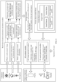
- FIG. 3 is a block diagram of a software structure of an electronic device according to an embodiment of this application.
- the software structure of the electronic device may be a layered architecture.
- software may be divided into several layers, and each layer has a clear role and task.
- the layers communicate with each other through a software interface.
- an Android system is divided into four layers: an application layer, a framework (framework, FWK) layer, an Android runtime (Android runtime) and system library, and a kernel layer from top to bottom.
- the application layer may include a series of applications. As shown in FIG. 3 , the application layer may include a camera application, a voice assistant application, an AR application, a music application, a video application, a map application, a third-party application, and the like.
- the third-party application may be a WeChat application, an iQIYI application, or the like.
- the framework layer provides an application programming interface (application programming interface, API) and a programming framework for an application at the application layer.
- the application framework layer may include some predefined functions. As shown in FIG. 3 , the application framework layer may include a system service (System Service), a view system (View System), a web service (Web Service), a phone manager, a resource manager, and the like.
- the system service may include a window manager service (window manager service, WMS), and an activity manager service (activity manager service, AMS).
- WMS window manager service
- AMS activity manager service
- the system service may further include a system-level service, namely, an AR manager service. The following describes each service in the system service.
- the window manager service is to provide a window manager service for a window (window), to specifically control display, hiding, and locations of all windows on a display.
- the window manager service may be specifically responsible for the following functions: 1. allocating a display surface (surface) to each window; 2. managing a display sequence, size, and location of the surface; 3. invoking a management function (such as a surface control function (SurfaceControl.Transaction)), to adjust transparency, a stretch coefficient, a location, and a size of the window, to implement animation effect of the window; and 4. providing a function related to an input system (for example, when the electronic device receives a touch event, the electronic device may provide, by using a window manager service, a proper window for a user to display or process this message).
- a management function such as a surface control function (SurfaceControl.Transaction)
- the activity manager service is to provide a manager service for an activity (activity) in an application.
- the activity manager service may be, but is not limited to, responsible for the following functions: 1. uniformly scheduling life cycles of activities of all applications; 2. starting or ending an application process; 3. starting and scheduling a life cycle of the service; 4. registering a broadcast receiver (Broadcast Receiver), and receiving and distributing a broadcast (Broadcast); 5. querying a current running status of the system; and 6. scheduling a task (task).
- the AR manager service is to implement the AR interaction method provided in this embodiment of this application, and provide an AR interaction service.
- the AR manager service may be, but is not limited to, responsible for the following functions: 1. constructing a world coordinate system; 2. determining a location and posture information of a real object in the world coordinate system; 3. recognizing a location of a real sound source in the world coordinate system; 4. determining a location and posture information of a virtual object in the world coordinate system; 5. generating 3D audio data based on at least one of the following items: the location and posture information of the real object, the location of the real sound source, and the location and posture information of the virtual object; and 6. generating, based on at least one of the following items: the location and posture information of the real object, the location of the real sound source, and the location and posture information of the virtual object, an AR image including the virtual object.
- the view system includes visual controls such as a control for displaying a text and a control for displaying an image.
- the view system may be configured to construct an application.
- An interface may include one or more controls.
- an interface including an SMS message notification icon may include the control for displaying a text and the control for displaying an image.
- the web service is an API that can be invoked through a web page.
- the phone manager is configured to provide a communication function of the electronic device, for example, management of a call status (including answering, declining, or the like).
- the resource manager provides various resources such as a localized character string, an icon, an image, a layout file, and a video file for an application.
- the Android runtime includes a kernel library (Kernel Library) and a virtual machine.
- the Android runtime is responsible for scheduling and management of the Android system.
- the kernel library includes two parts: a function that needs to be called by the Java language and the kernel library of the Android system, and is configured to provide an input/output service (Input/Output Service) and a kernel service (Kernel Service) for the Android system.
- the application layer and the framework layer may run on the virtual machine.
- the virtual machine executes Java files at the application layer and the framework layer as binary files.
- the virtual machine is configured to implement functions such as object lifecycle management, stack management, thread management, security and exception management, and garbage collection.
- the system library may include a plurality of functional modules, for example, a virtual object model library, a media library (media library), and an image processing library.
- the virtual object model library may be configured to manage a plurality of virtual object models. Each virtual object model is used to generate a virtual object. Each virtual object model may not only set an image of a corresponding virtual object, but also set a sound feature, an action feature, and the like, and content such as an auditory response package and a visual response package of the virtual object.
- the media library supports playback and recording of audios and videos in a plurality of formats, and opening of static images in a plurality of formats.
- the media library may support a plurality of audio and video encoding formats, for example, MPEG-4, H.264, MP3, AAC, AMR, JPG, and PNG.
- the kernel layer is a layer between hardware and software.
- the kernel layer includes at least a display driver, a sensor driver, a processor driver, a camera driver, an audio driver, and the like, and is configured to drive hardware at a hardware layer.
- the hardware layer may include various sensors, a display, a processor, an input device, a memory, a camera, and the like.
- an embodiment of this application provides an AR interaction method.
- the method may implement virtual-real audio-visual interaction shown in FIG. 1 .
- the following describes this solution in detail with reference to FIG. 4 based on the hardware structure of the electronic device shown in FIG. 2 and the software structure of the electronic device shown in FIG. 3 .
- software for implementing the AR interaction method in the electronic device may be divided into the following modules: a real object location and posture calculation module, a storage module, a virtual object model library, and an AR synthesis module.
- the method further needs to be implemented in cooperation with some other components inside or outside the electronic device.
- these components may be classified into two categories: collection components and output components.
- the collection components may include: a camera, a motion sensor (the following only use an IMU in the motion sensor as an example for description), and a microphone.
- the output components may include a display, a speaker, or a headset.
- the camera is configured to photograph a real scenario, to obtain an image of the real scenario (a real-scenario image for short).
- the IMU is configured to measure posture information of the electronic device.
- the posture information of the electronic device represents a motion posture of the electronic device, and may include posture angles and accelerations of the electronic device on three directional axes. Optionally, every two of the three directional axes are orthogonal to each other, to form a world coordinate system.
- the microphone is configured to collect a sound in the real scenario, to obtain real-scenario sound information.
- the real object location and posture calculation module specifically includes the following functions: obtaining the real-scenario image captured by the camera and obtaining the posture information of the electronic device measured by the IMU; constructing, based on the obtained real-scenario image and the posture information of the electronic device, a world coordinate system that uses the electronic device as an origin of coordinates; recognizing a real object in the real-scenario image, and determining a location of the real object in the world coordinate system (the location of the real object for short) and posture information of the real object in the world coordinate system; obtaining the real-scenario sound information collected by the microphone; calculating a physical location of the real sound source based on the real-scenario sound information; and converting the physical location of the real sound source into a location of the real sound source in the world coordinate system (the location of the real sound source for short).
- the posture information of the real object represents a motion posture of the real object, and may include posture angles and accelerations of the real object on three directional axes of the world coordinate system.
- the physical location of the real sound source can represent a location relationship between the real sound source and the microphone (that is, the electronic device), for example, a direction in which the real sound source is located relative to the electronic device, and a distance between the real sound source and the electronic device.
- the real object location and posture calculation module may construct the world coordinate system based on the obtained real-scenario image and the posture information of the electronic device according to a simultaneous localization and mapping (simultaneous localization and mapping, SLAM) algorithm or another algorithm.
- SLAM simultaneous localization and mapping
- the real object location and posture calculation module may use a corner of a display of the electronic device as an origin of coordinates, or use a central point of a side of the display as an origin of coordinates, or use a central point of the display as an origin of coordinates, or use a set location on the display as an origin of coordinates.
- the world coordinate system may be shown in FIG. 5A .
- the origin of coordinates is the central point of the side of the display, a virtual world can be displayed in the display, and a real world is outside the display.
- the real object location and posture calculation module may determine the location and posture information of the real object in a plurality of manners. Because the size of the real object is large, to ensure accuracy, the real object location and posture calculation module may use a location and posture information of a key portion of the real object as the location and posture information of the real object.
- the real object location and posture calculation module may recognize the key portion of the real object in the real-scenario image, collide the key portion of the real object with a SLAM point cloud, and calculate the location and posture information of the key portion based on a collision value.
- a SLAM point cloud collision result is shown in FIG. 5B .
- (a) in FIG. 5B is the real object in the real-scenario image
- (b) in FIG. 5B is a simulation diagram of a SLAM point cloud collision result.
- the real object location and posture calculation module may recognize the key portion of the real object in the real-scenario image, determine feature information of the key portion of the real object by using an image recognition technology, and finally determine the location and posture information of the real object based on the feature information of the key portion.
- the key portion may be a head
- the real object location and posture calculation module may recognize feature information of the head (for example, including an eye, a nose, an ear, and a mouth) of the person or the animal.
- the real object location and posture calculation module may recognize the key portion of the real object in the real-scenario image in a plurality of manners.
- the real object location and posture calculation module may recognize a head of the real object by using a facial recognition technology or a skeletal feature recognition technology.
- the real object location and posture calculation module may use a 3D physical recognition technology, to recognize the key portion of the real object in the real-scenario image.
- the real object location and posture calculation module may determine the location relationship between the real sound source and the microphone (that is, the physical location of the real sound source) by using a conventional sound source positioning technology, and finally convert the location relationship between the real sound source and the microphone into the location of the real sound source in the world coordinate system.
- the storage module is configured to store the location and posture information of the real object calculated by the real object location and posture calculation module, and store the location of the real sound source.
- the virtual object model library is configured to store at least one virtual object model.
- Each virtual object model may include, but is not limited to, at least one of the following: an image model, a sound feature, an action feature, a sound response package, and an action response package.
- the image model is used to set an image of the virtual object.
- the sound feature is used to set a sound emitted by the virtual object, and may specifically include a volume, a timbre, a pitch, and the like.
- the action feature is used to set an action that can be performed by the virtual object, and may specifically include an action type, an action amplitude, and the like.
- the sound response package includes a correspondence between sensing information of a plurality of virtual objects and an original sound that needs to be emitted.
- the action response package includes a correspondence between sensing information of a plurality of virtual objects and an action that needs to be performed.
- the sensing information of the virtual object may include, but is not limited to, the following two types: visual sensing information and auditory sensing information.
- the visual sensing information includes the location and posture information of the real object, an action of the real object, and the like that are calculated by the real object location and posture calculation module.
- the auditory sensing information includes the location of the real sound source, a sound instruction sent by the real sound source, and the like.
- the sensing information of the virtual object may further include touch operations performed by the user on the virtual object by using the display, and these touch operations may also be referred to as tactile sensing information.
- the sound instruction sent by the real sound source may be obtained by performing voice recognition on the real-scenario sound information by using a voice recognition technology.
- the following uses a virtual object model in which the virtual object is a person as an example, to describe the virtual object model in detail.
- the image model may specifically set a gender, a height, a weight, a body ratio, facial features, a clothing feature, another visual feature (a location of a facial spot), and the like.
- the sound feature may specifically set a volume, a timbre, and a tone, so that a sound feature of a sound emitted by the virtual object conforms to the image of the virtual object.
- the action feature may specifically set a basic action that can be performed by the virtual object, for example, walking, running, jumping, handshake, and waving. Any one of these basic actions may be an independent action response of the virtual object, or may be repeated for a plurality of times or combined with another basic action, to form an action response of the virtual object.
- the sound response package may include: When the sensing information of the virtual object represents that the real object approaches, a corresponding original sound is "Hello”; when the sensing information of the virtual object represents that the real object leaves, a corresponding original sound is "Goodbye”; and when the user performs a touch operation of tapping the virtual object by using the display, a corresponding original sound is laughter.
- the action response package may include: When the sensing information of the virtual object represents that the real object approaches, a corresponding action is approaching, reaching out, and shaking hands; when the sensing information of the virtual obj ect represents that the real obj ect leaves, a corresponding action is raising a hand, and waving; and when the user performs a touch operation of tapping the virtual object by using the display, a corresponding action is shaking.
- the AR synthesis module is configured to: synthesize an AR image and 3D audio data by using the AR technology, display the AR image on the display, and play the 3D audio data by using the speaker, the headset, and the like.
- the AR synthesis module may specifically include an AR image generation module and a 3D sound generation module.
- the AR image generation module may specifically synthesize the AR image by performing the following steps.
- the AR image generation module determines a location and posture information of the virtual object.
- the AR image generation module may determine the location and posture information of the virtual object in a plurality of manners.
- the AR image generation module determines the location and posture information of the virtual object in real time based on at least one of the following: the location and posture information of the real object, the action of the real object, the location of the real sound source, the sound instruction sent by the real sound source, the image model, the action feature, and the action response package in the virtual object model, and the touch operation performed by the user on the virtual object by using the display.
- the posture information of the virtual object represents a motion posture of the virtual object, and may include posture angles and accelerations of the virtual object on three directional axes of the world coordinate system.
- the location and posture information of the virtual object may be set by the electronic device, or set by the user, or set by the virtual object model.
- the AR image generation module may synthesize the AR image based on the location and posture information of the virtual object. For this process, refer to a conventional AR image synthesis technology. Details are not described herein again.
- the AR image generation module may further synthesize the AR image by using the real-scenario image.
- the 3D sound generation module may further specifically synthesize the 3D audio data by performing the following steps.
- the 3D sound generation module may determine original sound data of the virtual object based on at least one of the following: the location and posture information of the real object, the action of the real object, the location of the real sound source, the sound instruction sent by the real sound source, the sound feature, the sound response package, and the touch operation performed by the user on the virtual object by using the display.
- the 3D sound generation module generates the 3D audio data based on the location and posture information of the real object, the location and posture information of the virtual object, and the original sound data.
- the step B2 may specifically include the following steps.
- the 3D sound generation module calculates distances between two ears of the virtual object and two ears of the real object based on the location and posture information of the real object and the location and posture information of the virtual object.
- the 3D sound generation module calculates a volume difference and a time difference between the two ears of the real object based on the distances between the two ears of the virtual object and the two ears of the real object.
- the 3D sound generation module generates the 3D audio data based on the obtained volume difference and time difference between the two ears of the real object and the original sound data.
- the 3D sound generation module may further filter the 3D audio data based on the posture information of the real object, to further improve authenticity of a 3D sound.
- the display in the output components is configured to display the AR image.
- the speaker or the headset in the output components is configured to play the 3D audio data. In this way, the user can hear the 3D sound, and perceive a location of a virtual sound source (that is, the virtual object) through sound source positioning.
- the electronic device may obtain the real-scenario image, the posture information of the electronic device, and the real-scenario sound information in real time or periodically, to help update an audio-visual response of the virtual object in real time or periodically, so that the virtual object can quickly make a corresponding audio-visual response based on a perceived real world, to improve authenticity of the virtual object.
- the real object location and posture calculation module, the storage module, and the AR synthesis module in the foregoing AR interaction solution may be implemented by using the AR manager service in the system service at the framework layer of the electronic device, and the virtual object model library in this solution may be implemented by using the virtual object model located in the system library.
- interaction between each module in this solution and each of the collection component and the output component may be implemented by using a client, for example, implemented by the AR application at the application layer. It is clear that, this solution may be implemented by combining a background system service and a foreground client.
- virtual-real interaction that combines visual and auditory perceptions can be implemented, to bring better immersive experience to the user of the AR application.
- a virtual role can perceive the location and the posture of the real object and the location of the real sound source, and make a corresponding action response and a corresponding sound response based on the foregoing information, so that an intelligence level of the virtual object can be improved, to improve experience of virtual-real interaction.
- this solution may be implemented by using an architecture of a server and a client, so that operability of the client is higher, to help a developer develop a rich and colorful immersive AR application.
- this application further provides a plurality of embodiments, to respectively implement different virtual-real audio-visual interaction shown in FIG. 6 .
- virtual-real audio-visual interaction for example, a virtual object seeing a reality object, a reality object hearing a virtual object, and a virtual object hearing a reality object can be implemented respectively in the following embodiments. That the virtual object sees the reality object means that the virtual object may make an action response or a sound response based on a location and posture information of a real object in a field of view of the virtual object.
- That the reality object hears the virtual object means that the virtual object may make a 3D sound based on a location and posture information of the real object and a location and posture information of the virtual object, so that the real object can hear the 3D sound, and the location of the virtual object is arranged through sound source positioning. That the virtual object hears the reality object means that the virtual object may determine a physical location of a real sound source based on real-scenario sound information collected by a microphone, and make an action response or a sound response based on the location of the real sound source.
- the electronic device obtains a real-scenario image captured by a camera, and obtains posture information of the electronic device collected by a motion sensor (IMU).
- IMU motion sensor
- the electronic device constructs, based on the real-scenario image and the posture information of the electronic device, a world coordinate system that uses the electronic device as an origin of coordinates.
- the electronic device may construct the world coordinate system according to a SLAM algorithm.
- the electronic device may directly use the world coordinate system subsequently until the world coordinate system becomes invalid (for example, the electronic device moves); or periodically update the world coordinate system.
- a length of an update periodicity is not limited in this application, and the update periodicity may be greater than or equal to a capturing periodicity of the real-scenario image.
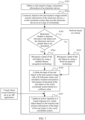
- S703 The electronic device determines whether a distance between the real object and the electronic device is greater than a set threshold; and if yes, S704 is performed; otherwise, S705 is performed.
- the electronic device may determine the distance between the real object and the electronic device in a plurality of manners.
- the electronic device may detect the distance between the real object and the electronic device by using an internal infrared sensor, an internal ultrasonic sensor, or the like.
- S706 The electronic device collides the head of the real object in the real-scenario image with a SLAM point cloud, and calculates a location and posture information of the head of the real object in the world coordinate system based on a collision value, for example, as shown in FIG. 5B .
- a collision value for example, as shown in FIG. 5B .
- the electronic device may further determine the location and posture information of the head of the real object in the world coordinate system according to another method. For example, when the distance between the real object and the electronic device is less than or equal to the set threshold, the electronic device may determine feature information of the head (for example, feature information of at least one of an eye, a nose, an ear, and a mouth) of the real object by using the image recognition technology, and finally determine the location and posture information of the real object based on the feature information of the head.
- feature information of the head for example, feature information of at least one of an eye, a nose, an ear, and a mouth
- the electronic device updates the action response or the sound response of the virtual object based on the location and posture information of the head of the real object in the world coordinate system.
- the visual sensing information of the virtual object includes a location and posture information of the real object, an action of the real object, and the like that are calculated by a real object location and posture calculation module.
- the electronic device may repeatedly perform S703 to S707 based on an update periodicity of the real-scenario image (that is, perform S703 to S707 based on a frame), so that the virtual object can make a response based on real-time visual sensing information.
- the electronic device may construct, by using an existing SLAM technology based on the real-scenario image photographed by the camera and the posture information of the electronic device collected by the IMU, the world coordinate system that uses the electronic device as the origin of coordinates.
- the electronic device may use a field of view of the camera as the field of view of the virtual object, to determine the location and posture information of the real object in the field of view of the virtual object in the world coordinate system, and further enable the virtual object to perform, based on the location and posture information of the real object, a corresponding action. For example, when a real person appears in a visual range of the virtual object, eyes of the virtual object adaptively follows the real person, and/or moves with the real person.
- the electronic device may update, based on an update periodicity of a real-scenario image, a location and posture information of a head of the real object in a world coordinate system, and a location and posture information of the virtual object in the world coordinate system. This specifically includes step S8011 and step S8012.
- S8011 The electronic device updates the location and posture information of the head of the real object in the world coordinate system. For a specific process, refer to the method described in S701 to S706 in the embodiment shown in FIG. 7 . Details are not described herein again.
- the electronic device updates the location and posture information of the virtual object in the world coordinate system.
- the location and posture information of the virtual object in the world coordinate system may be set by the electronic device, or set by a user, or may be determined by the electronic device in real time.
- the electronic device may determine the location and posture information of the virtual object in the world coordinate system with reference to the step A1 performed by the AR image generation module in the embodiment shown in FIG. 4 .
- the electronic device may perform the following step S802 to step S804.
- the electronic device determines original sound data of the virtual object. Similar to S8012 in which the electronic device determines the location and posture information of the virtual object in the world coordinate system, the original sound data of the virtual object may be set by the electronic device, or set by the user, or may be determined by the electronic device in real time. For example, the electronic device may determine the original sound data of the virtual object with reference to the step B1 performed by the 3D sound generation module in the embodiment shown in FIG. 4 .
- the electronic device generates 3D audio data based on the location and posture information of the head of the real object in the world coordinate system, the location and posture information of the virtual object in the world coordinate system, and the original sound data of the virtual object. This may specifically include steps S8031 to S8034.
- the electronic device separately determines distances between two ears of the virtual object and two ears of the real object (namely, a distance between the left ear of the virtual object and the left ear of the real object, and a distance between the right ear of the virtual object and the right ear of the real object) based on the location and posture information of the head of the real object in the world coordinate system and the location and posture information of the virtual object in the world coordinate system.
- the electronic device calculates a volume difference and a time difference between the two ears of the real object based on the distances between the two ears of the virtual object and the two ears of the real object.
- the electronic device generates the 3D audio data based on the obtained volume difference and time difference between the two ears of the real object, and the original sound data.
- the electronic device may filter the 3D audio data based on the posture information of the head of the real object, to further improve authenticity of the 3D sound.
- the sound In a process of transmitting a sound in a transmission medium, the sound may undergo various reflections and refractions. Therefore, by filtering the 3D audio data, reflections and refractions of the 3D audio data in the transmission process may be simulated, to make a 3D sound heard by the real object more authentic.
- S804 The electronic device plays the 3D audio data by using a speaker or a headset. The real object may hear the 3D sound, and perform sound source positioning based on the 3D sound, to perceive the location of the virtual object.
- the electronic device may update the location and posture information of the virtual object and the location and posture information of the real object in real time, so that the 3D audio data may be synthesized based on a location and posture relationship between the virtual object and the real object, to make the played 3D sound more authentic.
- a virtual musical instrument in the virtual world may emit a 3D sound according to the foregoing method, and a person in the real world may determine a specific location of the virtual musical instrument in the virtual world based on the 3D sound emitted by the headset.
- a person in the real world may determine, by using the 3D sound emitted by the headset, the virtual character from which the sound comes.
- each virtual object may emit a 3D sound according to the foregoing method.
- a person in the real world may determine, based on the 3D sound emitted by the headset, a specific virtual object that exists in the virtual world, a location of the virtual object, and the like, so that the person in the real world feels more immersive.
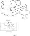
- a virtual object (a virtual cat) in the virtual world may send a 3D sound (mew) according to the foregoing method.
- a person in the real world may determine, by using the 3D sound emitted by the headset, that the virtual cat is located in the middle of a sofa rather than on a tea table, to ensure that what a person hears by using the headset is consistent with what is seen by using the display of the electronic device.
- the electronic device may implement, by using but not limited to the following functions: an original sound calculation function, a pose calculation function, and a 3D sound synthesis function, the AR interaction method shown in FIG. 8 .
- the 3D sound synthesis function may invoke the original sound calculation function, to obtain the original sound data of the virtual object; and invoke the pose calculation function, to update the location and posture information of the virtual object and the location and posture information of the real object in real time; and finally, the 3D audio data may be generated based on the original sound data of the virtual object, the location and posture information of the virtual object, and the location and posture information of the real object.
- S1101 The electronic device constructs a world coordinate system that uses the electronic device as an origin of coordinates. For a specific process, refer to descriptions in S701 and S702 in the embodiment shown in FIG. 7 . Details are not described herein again.
- S1102 The electronic device collects the real-scenario sound information in real time by using a microphone, and determines a location of the real sound source in the world coordinate system through sound source positioning. This may specifically include step S1 1021 and step S1 1022.
- S11021 The electronic device collects the real-scenario sound information in real time by using the microphone, and determines the physical location of the real sound source through sound source positioning.
- the physical location of the real sound source can represent a location relationship between the real sound source and the microphone (that is, the electronic device), for example, a direction in which the real sound source is located relative to the electronic device, and a distance between the real sound source and the electronic device.
- S11022 The electronic device converts the physical location of the real sound source into the location of the real sound source in the world coordinate system.
- S1103 When virtual object auditory listening is set in an AR application (that is, the virtual object performs an action response and/or a sound response based on auditory sensing information), the electronic device updates the action response and/or the sound response of the virtual object based on the location of the real sound source in the world coordinate system.
- the auditory sensing information of the virtual object includes the location of the real sound source in the world coordinate system, a sound instruction sent by the real sound source, and the like.
- a specific process of this step refer to the process of generating the AR image and generating the 3D audio data by the AR synthesis module in the embodiment shown in FIG. 4 , and details are not described herein again.
- the virtual object in the virtual world may recognize the location of the real sound source, and make the action response or the sound response based on the location of the real sound source. For example, when a person in the real world makes a blowing sound, a seed that is of a dandelion in the virtual world and that is close to the real sound source, may spread and float with a wind. For another example, when a person in the real world makes a shout, a flock of birds in the virtual world that are close to the location of the real sound source may perform an action of flying far away.
- Embodiment 1 and Embodiment 3 provided in this application may be separately implemented, or may be implemented in combination. This is not limited in this application.
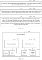
- this application further provides an AR interaction method. As shown in FIG. 12 , the method includes the following steps.
- the electronic device determines pose information of the real object and/or the location of the real sound source in the real scenario, and the pose information of the real object represents a location and posture of the real object.
- the electronic device may determine the pose information of the real object by performing the following steps: The electronic device obtains a second real-scenario image captured by the camera, and recognizes a key portion of a real object in the second real-scenario image. The electronic device determines pose information of the key portion of the real object in the second real-scenario image by using a simultaneous localization and mapping SLAM point cloud collision detection technology. The electronic device uses the pose information of the key portion of the real object as the pose information of the real object.
- the electronic device may determine the location of the real sound source by performing the following steps: The electronic device obtains the real-scenario sound information collected by the microphone, and determines the location relationship between the real sound source and the microphone through sound source positioning. The electronic device determines the location of the real sound source in the real scenario based on the location relationship between the real sound source and the microphone.
- the electronic device determines pose information of the virtual object based on the pose information of the real object and/or the location of the real sound source, and the pose information of the virtual object represents a location and posture of the virtual object.
- the electronic device may further establish the world coordinate system that uses the electronic device as the origin of coordinates.
- the electronic device may establish the world coordinate system by performing the following steps: obtaining a first real-scenario image captured by the camera, and obtaining posture information of the electronic device measured by an inertial measurement unit; and establishing the world coordinate system based on the first real-scenario image and the posture information of the electronic device.
- the pose information of the real object specifically represents the location and posture of the real object in the world coordinate system;
- the location of the real sound source is a location of the real sound source in the world coordinate system;
- the pose information of the virtual object specifically represents the location and posture of the virtual object in the world coordinate system.
- the electronic device may determine the pose information of the virtual object based on the pose information of the real object and/or the location of the real sound source, and at least one of the following: an action of the real object recognized based on the pose information of the real object, the sound instruction sent by the real sound source, an image model, an action feature, and an action response package in a virtual object model corresponding to the virtual object, and a touch operation performed by a user on the virtual object by using a display.
- the electronic device generates, based on the pose information of the virtual object, an AR image including the virtual object; and displays the AR image; and/or generates 3D audio data of the virtual object based on the pose information of the real object and the pose information of the virtual object; and plays the 3D audio data.
- the electronic device may generate the 3D audio data of the virtual object by performing the following steps: The electronic device separately determines distances between two ears of the virtual object and two ears of the real object based on the pose information of the real object and the pose information of the virtual object.
- the electronic device calculates a volume difference and a time difference between the two ears of the real object based on the distances between the two ears of the virtual object and the two ears of the real object.
- the electronic device generates the 3D audio data based on the volume difference and the time difference of the real object and original sound data of the virtual object.
- the original sound data is set, or is determined based on at least one of the following: location and posture information of the real object, the pose information of the virtual object, the action of the real object recognized based on the pose information of the real object, the sound instruction sent by the real sound source, the image model, the action feature, and the action response package in the virtual object model corresponding to the virtual object, and the touch operation performed by the user on the virtual object by using the display.
- the electronic device may further filter the 3D audio data based on the pose information of the real object, so that reflections and refractions of the 3D audio data in a transmission process may be simulated, to make a 3D sound heard by the real object more authentic.
- This embodiment of this application provides an AR interaction method.
- the electronic device may determine the pose information of the virtual object based on the pose information of the real object or the location of the real sound source, to generate and display the AR image, and may further generate and play the 3D sound data of the virtual object based on the pose information of the real object and the pose information of the virtual object.
- the virtual object may perceive the pose of the real object and the location of the real sound source, and make a corresponding action response or sound response based on the foregoing information, so that the virtual object may be the same as the real object. Therefore, in this method, virtual-real interaction that combines visual and auditory perceptions of the virtual object and the real object is implemented. This can improve an intelligent level of the virtual object, and further improves experience of virtual interaction.
- an electronic device 1300 may include a determining unit 1301, an AR synthesis unit 1302, a display unit 1303, and an audio unit 1304.
- the display unit 1303 is configured to present a user interface (for example, an AR image), to implement human-computer interaction. Same as the display unit 204 in the electronic device shown in FIG. 2 , the display unit 1303 includes a display panel, and the display panel is also referred to as a display.
- a user interface for example, an AR image
- the audio unit 1304 is configured to collect a sound signal and play audio data. Similar to the audio circuit 206 in the electronic device shown in FIG. 2 , the audio unit 1304 may include a speaker and a microphone.
- the determining unit 1301 is configured to: determine pose information of a real object and/or a location of a real sound source in a real scenario, where the pose information of the real object represents a location and posture of the real object; and determine pose information of a virtual object based on the pose information of the real object and/or the location of the real sound source, where the pose information of the virtual object represents a location and posture of the virtual object.
- the AR synthesis unit 1302 is configured to: generate, based on the pose information of the virtual object, an AR image including the virtual object; and/or generate three-dimensional 3D audio data of the virtual object based on the pose information of the real object and the pose information of the virtual object.
- the display unit 1303 is configured to display the AR image.
- the audio unit 1304 is configured to play the 3D audio data.
- the determining unit 1301 is further configured to: establish a world coordinate system that uses the electronic device as an origin of coordinates.
- the pose information of the real object specifically represents the location and posture of the real object in the world coordinate system.
- the location of the real sound source is the location of the real sound source in the world coordinate system.
- the pose information of the virtual object specifically represents the location and posture of the virtual object in the world coordinate system.
- the determining unit 1301 when establishing the world coordinate system that uses the electronic device as the origin of coordinates, is specifically configured to:
- the determining unit 1301 is specifically configured to:
- the determining unit 1301 when determining the location of the real sound source in the real scenario, is specifically configured to:
- the AR synthesis unit 1302 when determining the pose information of the virtual object based on the pose information of the real object and/or the location of the real sound source, is specifically configured to: determine the pose information of the virtual object based on the pose information of the real object and/or the location of the real sound source, and at least one of the following: an action of the real object recognized based on the pose information of the real object, a sound instruction sent by the real sound source, an image model, an action feature, and an action response package in a virtual object model corresponding to the virtual object, and a touch operation performed by a user on the virtual object by using a display.
- the AR synthesis unit 1302 when generating the 3D audio data of the virtual object based on the pose information of the real object and the pose information of the virtual object, is specifically configured to:
- the original sound data is set, or is determined based on at least one of the following: location and posture information of the real object, the pose information of the virtual object, the action of the real object recognized based on the pose information of the real object, the sound instruction sent by the real sound source, the image model, the action feature, and the action response package in the virtual object model corresponding to the virtual object, and the touch operation performed by the user on the virtual object by using the display.
- the AR synthesis unit 1302 is further configured to: before the audio unit 1304 plays the 3D audio data, filter the 3D audio data based on the pose information of the real object.
- division into modules is an example, and is only a logical function division. During actual implementation, there may be another division manner.
- functional units in embodiments of this application may be integrated into one processing unit, or may exist alone physically, or two or more units are integrated into one unit.
- the integrated unit may be implemented in a form of hardware, or may be implemented in a form of a software functional unit.
- the integrated unit When the integrated unit is implemented in the form of the software functional unit and sold or used as an independent product, the integrated unit may be stored in a computer-readable storage medium. Based on such an understanding, the technical solutions of this application essentially, or the part contributing to the current technology, or all or some of the technical solutions may be implemented in the form of a software product.
- the computer software product is stored in a storage medium and includes several instructions for instructing a computer device (which may be a personal computer, a server, or a network device) or a processor (processor) to perform all or some of the steps of the methods described in the embodiments of this application.
- the foregoing storage medium includes any medium that can store program code, such as a USB flash drive, a removable hard disk, a read-only memory (read-only memory, ROM), a random access memory (random access memory, RAM), a magnetic disk, or an optical disc.
- program code such as a USB flash drive, a removable hard disk, a read-only memory (read-only memory, ROM), a random access memory (random access memory, RAM), a magnetic disk, or an optical disc.
- an embodiment of this application further provides an electronic device.
- the electronic device is configured to implement the AR interaction method provided in the foregoing embodiments, and has the function of the electronic device shown in FIG. 13 .
- an electronic device 1400 may include a processor 1401, a memory 1402, a camera 1403, a display 1404, and an audio circuit 1405.
- the electronic device 1400 may further include peripheral or internal hardware shown in FIG. 2 .
- the processor 1401 and another component are connected to each other.
- the processor 1401 and the another component may be connected to each other by using a bus.
- the bus may be a peripheral component interconnect (peripheral component interconnect, PCI) bus, an extended industry standard architecture (extended industry standard architecture, EISA) bus, or the like.
- PCI peripheral component interconnect
- EISA extended industry standard architecture
- the bus may be classified into an address bus, a data bus, a control bus, and the like. For ease of representation, only one bold line represents the bus in FIG. 14 , but this does not mean that there is only one bus or only one type of bus.
- the processor 1401 is configured to implement the AR interaction method provided in the foregoing embodiments, and the method includes:
- the memory 1402 is configured to store program instructions, data, and the like.
- the program instructions may include program code, and the program code includes computer operation instructions.
- the memory 1402 may include a random access memory (random access memory, RAM), or may be a nonvolatile memory (nonvolatile memory), for example, at least one magnetic disk memory.
- the processor 1401 executes a program stored in the memory 1402, and implements the foregoing functions by using the foregoing components, to finally implement the method provided in the foregoing embodiments.
- an embodiment of this application further provides a computer program.
- the computer program When the computer program is run on a computer, the computer is enabled to perform the method provided in the foregoing embodiments.
- an embodiment of this application further provides a computer storage medium.
- the computer storage medium stores a computer program.
- the computer program is executed by a computer, the computer is enabled to perform the method provided in the foregoing embodiments.
- an embodiment of this application further provides a chip.
- the chip is configured to read a computer program stored in a memory, to implement the method provided in the foregoing embodiments.
- an embodiment of this application further provides a chip system.
- the chip system includes a processor, configured to support a computer apparatus in implementing functions related to the electronic device in the method provided in the foregoing embodiments.
- the chip system further includes a memory.
- the memory is configured to store a program and data that are necessary for the computer apparatus.
- the chip system may include a chip, or may include a chip and another discrete component.
- an electronic device may determine pose information of a virtual object based on pose information of a real object or a location of a real sound source, to generate and display an AR image, and may further generate and play 3D sound data of the virtual object based on the pose information of the real object and the pose information of the virtual object.
- the virtual object may perceive a pose of the real object and the location of the real sound source, and make a corresponding action response or sound response based on the foregoing information, so that the virtual object may be the same as the real object. Therefore, in this method, virtual-real interaction that combines visual and auditory perceptions of the virtual object and the real object is implemented. This can improve an intelligent level of the virtual object, and further improves experience of virtual interaction.
- this application may be provided as a method, a system, or a computer program product. Therefore, this application may use a form of hardware only embodiments, software only embodiments, or embodiments with a combination of software and hardware. In addition, this application may use a form of a computer program product that is implemented on one or more computer-usable storage media (including but not limited to a disk memory, a CD-ROM, an optical memory, and the like) that include computer-usable program code.
- computer-usable storage media including but not limited to a disk memory, a CD-ROM, an optical memory, and the like
- These computer program instructions may be provided for a general-purpose computer, a dedicated computer, an embedded processor, or a processor of any other programmable data processing device, to generate a machine, so that the instructions executed by a computer or a processor of any other programmable data processing device generate an apparatus for implementing a specific function in one or more processes in the flowcharts and/or in one or more blocks in the block diagrams.
- These computer program instructions may be stored in a computer-readable memory that can instruct the computer or any other programmable data processing device to work in a specific manner, so that the instructions stored in the computer-readable memory generate an artifact that includes an instruction apparatus.
- the instruction apparatus implements a specific function in one or more processes in the flowcharts and/or in one or more blocks in the block diagrams.
- the computer program instructions may alternatively be loaded onto a computer or another programmable data processing device, so that a series of operations and steps are performed on the computer or the another programmable device, so that computer-implemented processing is generated. Therefore, the instructions executed on the computer or the another programmable device provide steps for implementing a specific function in one or more procedures in the flowcharts and/or in one or more blocks in the block diagrams.
Landscapes
- Engineering & Computer Science (AREA)
- Theoretical Computer Science (AREA)
- Physics & Mathematics (AREA)
- General Engineering & Computer Science (AREA)
- General Physics & Mathematics (AREA)
- Human Computer Interaction (AREA)
- Acoustics & Sound (AREA)
- Signal Processing (AREA)
- Computer Graphics (AREA)
- Software Systems (AREA)
- Computer Hardware Design (AREA)
- Computer Vision & Pattern Recognition (AREA)
- General Health & Medical Sciences (AREA)
- Audiology, Speech & Language Pathology (AREA)
- Health & Medical Sciences (AREA)
- Multimedia (AREA)
- User Interface Of Digital Computer (AREA)
Applications Claiming Priority (2)
| Application Number | Priority Date | Filing Date | Title |
|---|---|---|---|
| CN202011627072.0A CN114693890B (zh) | 2020-12-31 | 2020-12-31 | 一种增强现实交互方法及电子设备 |
| PCT/CN2021/140320 WO2022143322A1 (fr) | 2020-12-31 | 2021-12-22 | Procédé d'interaction à réalité augmentée et dispositif électronique |
Publications (3)
| Publication Number | Publication Date |
|---|---|
| EP4254353A1 true EP4254353A1 (fr) | 2023-10-04 |
| EP4254353A4 EP4254353A4 (fr) | 2024-05-08 |
| EP4254353B1 EP4254353B1 (fr) | 2026-03-04 |
Family
ID=82135246
Family Applications (1)
| Application Number | Title | Priority Date | Filing Date |
|---|---|---|---|
| EP21914061.3A Active EP4254353B1 (fr) | 2020-12-31 | 2021-12-22 | Procédé d'interaction à réalité augmentée et dispositif électronique |
Country Status (4)
| Country | Link |
|---|---|
| US (1) | US12581262B2 (fr) |
| EP (1) | EP4254353B1 (fr) |
| CN (1) | CN114693890B (fr) |
| WO (1) | WO2022143322A1 (fr) |
Families Citing this family (11)
| Publication number | Priority date | Publication date | Assignee | Title |
|---|---|---|---|---|
| CN112860072A (zh) * | 2021-03-16 | 2021-05-28 | 河南工业职业技术学院 | 一种虚拟现实多人交互协作方法与系统 |
| CN116132905A (zh) * | 2022-12-09 | 2023-05-16 | 杭州灵伴科技有限公司 | 音频播放方法和头戴式显示设备 |
| CN115988233A (zh) * | 2022-12-30 | 2023-04-18 | 广州方硅信息技术有限公司 | 直播进场秀展示处理方法、装置、电子设备和存储介质 |
| CN116047978B (zh) * | 2023-01-31 | 2025-09-19 | 联想(北京)有限公司 | 控制方法及装置 |
| CN116304180A (zh) * | 2023-03-06 | 2023-06-23 | 北京字跳网络技术有限公司 | 图像显示方法、装置、设备、存储介质及程序产品 |
| CN116610282B (zh) * | 2023-07-18 | 2023-11-03 | 北京万物镜像数据服务有限公司 | 一种数据处理方法、装置及电子设备 |
| CN116755587B (zh) * | 2023-08-11 | 2023-12-19 | 之江实验室 | 一种增强现实的方法、装置、存储介质及电子设备 |
| CN117407622B (zh) * | 2023-09-28 | 2026-04-28 | 天津华宁电子有限公司 | 一种用于虚拟场景生成的数据传透方法及系统 |
| CN117579804B (zh) * | 2023-11-17 | 2024-05-14 | 广东筠诚建筑科技有限公司 | 一种基于ar的装配式建筑构件预布局体验方法及装置 |
| CN118982636B (zh) * | 2024-07-22 | 2025-04-04 | 杭州慧建智联科技有限公司 | 一种用于mr设备的虚实对齐方法 |
| CN120499587B (zh) * | 2025-07-17 | 2025-09-26 | 深圳市立体通技术有限公司 | 立体声裸眼三维画面播放方法、装置、设备及介质 |
Family Cites Families (15)
| Publication number | Priority date | Publication date | Assignee | Title |
|---|---|---|---|---|
| JP2000350865A (ja) * | 1999-06-11 | 2000-12-19 | Mr System Kenkyusho:Kk | 複合現実空間のゲーム装置、その画像処理方法およびプログラム記憶媒体 |
| US9037468B2 (en) * | 2008-10-27 | 2015-05-19 | Sony Computer Entertainment Inc. | Sound localization for user in motion |
| US9901828B2 (en) * | 2010-03-30 | 2018-02-27 | Sony Interactive Entertainment America Llc | Method for an augmented reality character to maintain and exhibit awareness of an observer |
| US8970709B2 (en) * | 2013-03-13 | 2015-03-03 | Electronic Scripting Products, Inc. | Reduced homography for recovery of pose parameters of an optical apparatus producing image data with structural uncertainty |
| JP2014191718A (ja) * | 2013-03-28 | 2014-10-06 | Sony Corp | 表示制御装置、表示制御方法および記録媒体 |
| JP6307627B2 (ja) * | 2014-03-14 | 2018-04-04 | 株式会社ソニー・インタラクティブエンタテインメント | 空間感知を備えるゲーム機 |
| US9906885B2 (en) * | 2016-07-15 | 2018-02-27 | Qualcomm Incorporated | Methods and systems for inserting virtual sounds into an environment |
| US9998847B2 (en) * | 2016-11-17 | 2018-06-12 | Glen A. Norris | Localizing binaural sound to objects |
| US10664993B1 (en) * | 2017-03-13 | 2020-05-26 | Occipital, Inc. | System for determining a pose of an object |
| CA3090281A1 (fr) * | 2018-02-15 | 2019-08-22 | Magic Leap, Inc. | Double position d'ecoute pour la realite mixte |
| CN108681402A (zh) * | 2018-05-16 | 2018-10-19 | Oppo广东移动通信有限公司 | 识别交互方法、装置、存储介质及终端设备 |
| CN111949112A (zh) * | 2019-05-14 | 2020-11-17 | Oppo广东移动通信有限公司 | 对象交互方法及装置、系统、计算机可读介质和电子设备 |
| US20200367008A1 (en) * | 2019-05-15 | 2020-11-19 | Dts, Inc. | System and method for rendering virtual sound sources |
| CN111880659A (zh) * | 2020-07-31 | 2020-11-03 | 北京市商汤科技开发有限公司 | 虚拟人物控制方法及装置、设备、计算机可读存储介质 |
| CN111897431B (zh) * | 2020-07-31 | 2023-07-25 | 北京市商汤科技开发有限公司 | 展示方法及装置、显示设备、计算机可读存储介质 |
-
2020
- 2020-12-31 CN CN202011627072.0A patent/CN114693890B/zh active Active
-
2021
- 2021-12-22 WO PCT/CN2021/140320 patent/WO2022143322A1/fr not_active Ceased
- 2021-12-22 EP EP21914061.3A patent/EP4254353B1/fr active Active
-
2023
- 2023-06-29 US US18/344,299 patent/US12581262B2/en active Active
Also Published As
| Publication number | Publication date |
|---|---|
| US20230345196A1 (en) | 2023-10-26 |
| EP4254353A4 (fr) | 2024-05-08 |
| CN114693890B (zh) | 2024-09-10 |
| CN114693890A (zh) | 2022-07-01 |
| WO2022143322A1 (fr) | 2022-07-07 |
| EP4254353B1 (fr) | 2026-03-04 |
| US12581262B2 (en) | 2026-03-17 |
Similar Documents
| Publication | Publication Date | Title |
|---|---|---|
| US12581262B2 (en) | Augmented reality interaction method and electronic device | |
| CN112634416B (zh) | 虚拟形象模型的生成方法、装置、电子设备及存储介质 | |
| US10007349B2 (en) | Multiple sensor gesture recognition | |
| CN108694073B (zh) | 虚拟场景的控制方法、装置、设备及存储介质 | |
| US11543242B2 (en) | Localization and visualization of sound | |
| CN105378625A (zh) | 指示视野外的增强现实图像 | |
| CN111880648A (zh) | 一种三维元素的操纵方法和终端 | |
| CN114026606A (zh) | 用于动态遮挡的快速手部网格划分 | |
| US20240168566A1 (en) | Finger Orientation Touch Detection | |
| CN114385854B (zh) | 资源推荐方法、装置、电子设备及存储介质 | |
| US12548538B2 (en) | Spatial music creation interface | |
| CN112927718B (zh) | 感知周围环境的方法、装置、终端和存储介质 | |
| CN114942737A (zh) | 显示方法、装置、显示设备、头戴式设备及存储介质 | |
| KR102405385B1 (ko) | 3d 컨텐츠를 위한 여러 오브젝트를 생성하는 방법 및 시스템 | |
| CN115633120B (zh) | 一种交互方法和设备 | |
| CN117149015A (zh) | 基于三维模型的产品展示方法及装置 | |
| WO2022222705A1 (fr) | Procédé de commande de dispositif et dispositif électronique | |
| CN116437284B (zh) | 空间音频合成方法、电子设备及计算机可读存储介质 | |
| EP3385869B1 (fr) | Procédé et appareil de présentation d'informations multimédia | |
| CN118433471B (zh) | 一种视频处理方法及相关电子设备 | |
| US11281337B1 (en) | Mirror accessory for camera based touch detection | |
| CN119105656A (zh) | 空中书写方法、智能笔、智能眼镜与计算机可读存储介质 | |
| CN115567667A (zh) | 一种多媒体数据处理方法、装置、电子设备及存储介质 | |
| CN120631283A (zh) | 二维码显示方法、终端设备及存储介质 | |
| CN119541000A (zh) | Hrtf的实现方法、装置、设备及计算机可读存储介质 |
Legal Events
| Date | Code | Title | Description |
|---|---|---|---|
| STAA | Information on the status of an ep patent application or granted ep patent |
Free format text: STATUS: THE INTERNATIONAL PUBLICATION HAS BEEN MADE |
|
| PUAI | Public reference made under article 153(3) epc to a published international application that has entered the european phase |
Free format text: ORIGINAL CODE: 0009012 |
|
| STAA | Information on the status of an ep patent application or granted ep patent |
Free format text: STATUS: REQUEST FOR EXAMINATION WAS MADE |
|
| 17P | Request for examination filed |
Effective date: 20230626 |
|
| AK | Designated contracting states |
Kind code of ref document: A1 Designated state(s): AL AT BE BG CH CY CZ DE DK EE ES FI FR GB GR HR HU IE IS IT LI LT LU LV MC MK MT NL NO PL PT RO RS SE SI SK SM TR |
|
| DAV | Request for validation of the european patent (deleted) | ||
| DAX | Request for extension of the european patent (deleted) | ||
| A4 | Supplementary search report drawn up and despatched |
Effective date: 20240409 |
|
| RIC1 | Information provided on ipc code assigned before grant |
Ipc: G06F 3/03 20060101ALI20240403BHEP Ipc: H04S 7/00 20060101ALI20240403BHEP Ipc: G06F 3/16 20060101ALI20240403BHEP Ipc: G06F 3/01 20060101ALI20240403BHEP Ipc: G06T 19/00 20110101AFI20240403BHEP |
|
| GRAP | Despatch of communication of intention to grant a patent |
Free format text: ORIGINAL CODE: EPIDOSNIGR1 |
|
| STAA | Information on the status of an ep patent application or granted ep patent |
Free format text: STATUS: GRANT OF PATENT IS INTENDED |
|
| INTG | Intention to grant announced |
Effective date: 20251030 |
|
| GRAS | Grant fee paid |
Free format text: ORIGINAL CODE: EPIDOSNIGR3 |
|
| GRAA | (expected) grant |
Free format text: ORIGINAL CODE: 0009210 |
|
| STAA | Information on the status of an ep patent application or granted ep patent |
Free format text: STATUS: THE PATENT HAS BEEN GRANTED |
|
| AK | Designated contracting states |
Kind code of ref document: B1 Designated state(s): AL AT BE BG CH CY CZ DE DK EE ES FI FR GB GR HR HU IE IS IT LI LT LU LV MC MK MT NL NO PL PT RO RS SE SI SK SM TR |
|
| REG | Reference to a national code |
Ref country code: CH Ref legal event code: F10 Free format text: ST27 STATUS EVENT CODE: U-0-0-F10-F00 (AS PROVIDED BY THE NATIONAL OFFICE) Effective date: 20260304 Ref country code: GB Ref legal event code: FG4D |
|
| REG | Reference to a national code |
Ref country code: IE Ref legal event code: FG4D |
|
| REG | Reference to a national code |
Ref country code: DE Ref legal event code: R096 Ref document number: 602021049507 Country of ref document: DE |