EP4254708A1 - Procédé et système de commande coordonnée de compensateur distribué, et dispositif informatique et support de stockage - Google Patents
Procédé et système de commande coordonnée de compensateur distribué, et dispositif informatique et support de stockage Download PDFInfo
- Publication number
- EP4254708A1 EP4254708A1 EP22770549.8A EP22770549A EP4254708A1 EP 4254708 A1 EP4254708 A1 EP 4254708A1 EP 22770549 A EP22770549 A EP 22770549A EP 4254708 A1 EP4254708 A1 EP 4254708A1
- Authority
- EP
- European Patent Office
- Prior art keywords
- modules
- phase
- module
- hot standby
- standby state
- Prior art date
- Legal status (The legal status is an assumption and is not a legal conclusion. Google has not performed a legal analysis and makes no representation as to the accuracy of the status listed.)
- Granted
Links
Images



Classifications
-
- H—ELECTRICITY
- H02—GENERATION; CONVERSION OR DISTRIBUTION OF ELECTRIC POWER
- H02J—ELECTRIC POWER NETWORKS; CIRCUIT ARRANGEMENTS OR SYSTEMS FOR SUPPLYING OR DISTRIBUTING ELECTRIC POWER; SYSTEMS FOR STORING ELECTRIC ENERGY
- H02J3/00—Circuit arrangements for AC mains or AC distribution networks
- H02J3/18—Arrangements for adjusting, eliminating or compensating reactive power in networks
- H02J3/1821—Arrangements for adjusting, eliminating or compensating reactive power in networks using shunt compensators
- H02J3/1835—Arrangements for adjusting, eliminating or compensating reactive power in networks using shunt compensators with stepless control
- H02J3/1842—Arrangements for adjusting, eliminating or compensating reactive power in networks using shunt compensators with stepless control having reactive elements actively controlled by bridge converters, e.g. active filters or static compensators [STATCOM]
-
- H—ELECTRICITY
- H02—GENERATION; CONVERSION OR DISTRIBUTION OF ELECTRIC POWER
- H02J—ELECTRIC POWER NETWORKS; CIRCUIT ARRANGEMENTS OR SYSTEMS FOR SUPPLYING OR DISTRIBUTING ELECTRIC POWER; SYSTEMS FOR STORING ELECTRIC ENERGY
- H02J3/00—Circuit arrangements for AC mains or AC distribution networks
- H02J3/26—Arrangements for eliminating or reducing asymmetry in polyphase networks
-
- H—ELECTRICITY
- H02—GENERATION; CONVERSION OR DISTRIBUTION OF ELECTRIC POWER
- H02J—ELECTRIC POWER NETWORKS; CIRCUIT ARRANGEMENTS OR SYSTEMS FOR SUPPLYING OR DISTRIBUTING ELECTRIC POWER; SYSTEMS FOR STORING ELECTRIC ENERGY
- H02J3/00—Circuit arrangements for AC mains or AC distribution networks
- H02J3/18—Arrangements for adjusting, eliminating or compensating reactive power in networks
- H02J3/1821—Arrangements for adjusting, eliminating or compensating reactive power in networks using shunt compensators
- H02J3/1835—Arrangements for adjusting, eliminating or compensating reactive power in networks using shunt compensators with stepless control
- H02J3/1842—Arrangements for adjusting, eliminating or compensating reactive power in networks using shunt compensators with stepless control having reactive elements actively controlled by bridge converters, e.g. active filters or static compensators [STATCOM]
- H02J3/1857—Arrangements for adjusting, eliminating or compensating reactive power in networks using shunt compensators with stepless control having reactive elements actively controlled by bridge converters, e.g. active filters or static compensators [STATCOM] the bridge converters being multilevel bridge converters or modular multilevel converters
Definitions
- This application relates to the field of flexible alternating-current transmission in power system, and in particular relates to a coordinated control method and system for a distributed compensator, and a computer device and a storage medium.
- each small-capacity compensator can be directly suspended on a power line in a distributed mode, thus the controlling function and effect of the power grid power flow similar to that of a static synchronous series compensator are achieved.
- a more flexible and more advanced control method can be provided for the smart grid, and the power supply capability, the safety and the stability of the power system are effectively improved.
- the distributed compensator has the characteristics of small size, light weight and the like. A large number of distributed subunits can guarantee the redundancy of devices, and then the reliability is improved. Meanwhile, distributed compensator devices can be dispersedly deployed on a power transmission line or a substation, so that the occupied area is small.
- a common distributed compensator structure includes three-phase voltage source converters which are connected into a three-phase alternating-current line in series respectively, the converters of each phase are formed by multiple modules sequentially connected in series, and three phases are kept balanced.
- the distributed compensator has a single circuit line operating mode and a multiple circuit line operating mode.
- An exemplary embodiment of this application provides a coordinated control method and system for a distributed compensator, and a computer device and a storage medium, which can quickly and stably treat the module fault in each phase of the distributed compensator, and ensure balanced control of all phases of all circuit lines in a case that a module of a certain phase of a certain circuit line has a fault, thus avoiding unbalanced disturbance to a power grid.
- this application provides a coordinated control method for a distributed compensator, the distributed compensator is composed of converters that are connected to three phases of alternating-current lines in series respectively, and the converters that are connected into each phase are formed by multiple modules sequentially connected in series.
- the method includes:
- the converter is a voltage source converter.
- the distributed compensator is in a single circuit line operating mode, and the distributed compensator is only connected to a single circuit alternating-current line in series.
- the calculating, in real time, the second number of modules, which can effectively output voltages, of the distributed compensator includes: determining the minimum value of the first number of modules of each phase in the single circuit alternating-current line as the second number of modules.
- the distributed compensator is in a multiple circuit line operating mode, and the distributed compensator are connected to parallel multiple circuit alternating-current lines in series.
- the calculating, in real time, the second number of modules, which can effectively output voltages, of the distributed compensator includes: receiving the minimum value of the first number of modules of each phase in each parallel multiple circuit alternating-current line, and determining a minimum value from the received minimum values as the second number of modules.
- the method further includes: sequentially determining whether each module of the phase has a fault in a case that the number of modules, the states of which need to be converted into the hot standby state, is larger than or equal to 1; converting the state of current module into the hot standby state in a case that the current module does not have a fault; and subtracting 1 from the number of modules, the states of which need to be converted into the hot standby state.
- the sequentially determining whether each module of the phase has a fault in a case that the number of modules, the states of which need to be converted into the hot standby state, is larger than or equal to 1 includes: subtracting 1 from the number of modules, the states of which need to be converted into the hot standby state, in a case that the current module has a fault, and skipping converting the current module into the hot standby state.
- the method further includes: keeping the operating state of each module of the phase, in which the modules, the states of which need to be converted into the hot standby state, are located unchanged in a case that the number of modules, the states of which need to be converted into the hot standby state, is equal to zero, and keeping calculating the number of modules, the states of which need to be converted into the hot standby state, of the phase in real time.
- the hot standby state is: a state that the module, the state of which needs to be converted into the hot standby state, is deblocked to operate and has voltage output capability, but the output voltage of the module, the state of which needs to be converted into the hot standby state, is kept to be 0.
- the converter is a voltage source converter.
- this application provides a coordinated control system for a distributed compensator; the distributed compensator is composed of converters that are connected to three phases of alternating-current lines in series respectively, and the converters of each phase are formed by multiple modules sequentially connected in series.
- the coordinated control system includes:
- the coordinated control system further includes: a multiple circuit line communication component configured to take effect only in a case that the distributed compensator is in a multiple circuit line operating mode, and determine the minimum value of the first number of modules in each parallel multiple circuit alternating-current line.
- the module hot standby state control component is configured to calculate, in real time, the number of modules, the states of which need to be converted into the hot standby state, in the converter of each phase; and in a case that the number of modules, the states of which need to be converted into the hot standby state, in one phase of each phase is zero, no module in the one phase is converted into the hot standby state.
- the operating state includes module deblocked, module blocked and module fault.
- this application provides a computer device, including a memory and a processor, the memory stores a computer program, and the processor executes the computer program to implement the steps of the method above.
- this application provides a computer readable storage medium, the computer readable storage medium stores a computer program, and the computer program is executed by the processor to implement the steps of the method above.
- coordinated control over the distributed compensator can be realized. That is, in a case that the module in a certain phase of the distributed compensator at a certain circuit line has a fault, the fault module of the fault phase will be bypassed rapidly, the number of available modules of all phases of all circuit lines will be updated at the same time, and moreover, the number of effective input modules of all the circuit lines will be calculated in real time.
- the corresponding number of modules are selected to be converted into the hot standby state according to the number of available modules of all the phases and the number of effective input modules of all the circuit lines, thus keeping the number of modules, which can effectively output voltages, of all the phases of all the circuit lines consistent, and then it ensures that all the phases are outputted consistently.
- coordinated balance control over all the phases of all the circuit lines is achieved.
- modular multi-level converter is adopted in the power flow controller or VSC-HVDC power transmission projects.
- the adopted treatment mode mostly excludes inter-phase coordinated control, but put redundant modules into the fault phase to replace the bypassed fault module.
- the converter will be triggered to be blocked.
- the distributed compensator has no specific redundancy design, and each module in series can be operated independently.
- the converter has the single-module operation capability, so the converter needs to be triggered to be blocked only in a case that all the modules in series of a certain phase have a fault.
- a coordinated control method which can quickly and stably treat the module fault of each phase of the distributed compensator is needed. It ensures balanced control of all phases of all circuit lines still in a case that the module has a fault.
- ordinal terms such as “first” and “second” to modify an element does not mean any priority, rank or order of one element relative to another, or the time order of performing actions in a method. Unless otherwise specified, such ordinal numbers are only used as a label to distinguish one element with a specific name from another element with the same name (except ordinal numbers in one embodiment).
- similar or same components with the same function are denoted by the same reference numerals, and different embodiments of similar or same components with the same function are distinguished by different letter suffixes of reference numerals with the same reference numerals.
- FIG. 1 is a flowchart of a treating method for module fault in a certain phase of existing power flow controller and VSC_HVDC power transmission project.
- N_RE_N redundant modules will be set in N series modules of the converter of each phase of the distributed compensator, and the number of operating modules will be set to be N_OP_N.
- the redundant modules do not output effective voltage.
- the fault module will be bypassed, one redundant module will be put into use, and 1 will be subtracted from the number N_RE of the remaining redundant modules, thus the number N_OP_N of the running modules of the phase is kept unchanged, and the original operating state of the converter will be maintained.
- N_RE N_RE_N-the number of fault modules.
- Each series module of the distributed compensator can be operated independently, and the converter has the single-module operation capability, so in a case that the method is adopted, the redundancy and the flexibility of the distributed compensator cannot be fully utilized.
- An exemplary embodiment of this application provides a coordinated control method and system for a distributed compensator, and a computer device and a storage medium, which ensures balanced control of all phases of all circuit lines and normal operation of the distributed compensator still in a case that a module of a certain phase of a certain circuit line has a fault, thus avoiding unbalanced disturbance to an alternating-current power grid.
- This application aims to provide a coordinated control method and system for a distributed compensator, and a computer device and a storage medium, which can quickly and stably treat the fault in a module of each phase of the distributed compensator, and ensure balanced control of all phases of all circuit lines still in a case that a module of a certain phase of a certain circuit line has a fault, thus avoiding unbalanced disturbance to an alternating-current power grid.
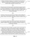
- FIG. 2 shows a flowchart of a coordinated control method for a distributed compensator according to an embodiment of this application.
- step S210 the distributed compensator is configured.
- the distributed compensator is composed of converters that are connected to three phases of alternating-current lines in series respectively, and the converters of each phase are formed by multiple modules sequentially connected in series.
- Step S220 the operating state of each module of the converter of each phase is checked.
- the operating state of each module among the multiple modules of the converter of each phase is checked in real time, so as to obtain the first number of modules of each phase, and the first number of modules is the number of available modules, which have normal operation conditions and do not have faults, in the converter of each phase.
- Step S230 the number of modules, which can effectively output voltages, of the distributed compensator is calculated.
- the second number of modules, which can effectively output voltages, of the distributed compensator is calculated in real time, and the second number of modules is equal to the minimum value of the first number of modules in each phase.
- Step S240 blocking and bypassing in a case that a module has a fault is performed.
- the fault module is blocked and bypassed in a case that any module of the converter of any phase has a fault, and in addition, one is subtracted from the first number of modules in the fault phase, and the first number of modules in a non-fault phase is kept unchanged.
- Step S250 the state of a module, which needs to be subjected to conversion is converted into a hot standby state.
- the first number of modules in each phase is compared with the second number of modules, and in a case that the first number of modules is greater than the second number of modules, the state of a module, which needs to be converted into hot standby state, in a converter of a phase, in which the first number of modules is greater than the second number of modules, is converted into the hot standby state.
- the number of modules, the states of which need to be converted into the hot standby state is equal to the difference of the first number of modules and the second number of modules in the phase in which the modules, the states of which need to be converted into the hot standby state.
- the converter is a three-phase voltage source converter.
- the calculating, in real time, the second number of modules, which can effectively output voltages, of the distributed compensator includes: the minimum value of the first number of modules of each phase in the single circuit alternating-current line is determined as the second number of modules.
- the calculating, in real time, the second number of modules, which can effectively output voltages, of the distributed compensator includes: the minimum value of the first number of modules of each phase in each parallel multiple circuit alternating-current line is received, and the minimum value from the received minimum values is determined as the second number of modules.
- FIG. 3 shows a schematic structural diagram of a coordinated control system for a distributed compensator according to an embodiment of this application.
- the distributed compensator includes converters connected to three phases of alternating-current lines in series respectively, and the converters of each phase are formed by multiple modules sequentially connected in series.
- the coordinated control system includes M circuit lines, the converters are connected to three phases of alternating-current lines in series respectively, and the converters of each phase are formed by sequentially connecting N modules in series.
- the converter of each phase includes a first module, a second module and so up to a N th module.
- FIG. 4 shows a schematic structural diagram of a coordinated control system for a distributed compensator according to an embodiment of this application.
- the coordinated control system for the distributed compensator includes a module state monitoring component 10, an effective module number calculation component 20, a module hot standby state control component 30 and a multiple circuit line communication component 40.
- the module state monitoring component 10 is configured to check, in real time, the operating state of each module in the converter of each phase of the distributed compensator and transmit the operating state of each module to the effective module number calculation component 20.
- the multiple circuit line communication component 40 is configured to take effect only in a case that the distributed compensator is in a multiple circuit line operating mode, summarize the minimum value of the number of available modules of the converter of each phase in each parallel multiple circuit alternating-current line, and transmit the minimum value of the number of available modules to the effective module number calculation component 20.
- the multiple circuit line communication component 40 can be omitted in a case of a single circuit line operating mode.
- the effective module number calculation component 20 is configured to calculate, in real time, the number of available modules of the converter of each phase, according to the operating state of each module, calculate, in real time, the second number of modules, which can effectively output voltages, of the distributed compensator, and transmit the number of modules which can effectively output voltages to the module hot standby state control component 30.
- the first number of modules is the number of available modules, which have normal operation conditions and do not have faults, in the converter of each phase.
- the module hot standby state control component 30 is configured to calculate, in real time, the number of modules, the states of which need to be converted into the hot standby state, in the converter of each phase and convert the modules, the states of which need to be converted into the hot standby state, in the converter of each phase into the hot standby state.
- the number of modules, the states of which need to be converted into the hot standby state, in the converter of each phase is equal to the difference of the number of available modules of the converter of each phase and the number of modules, which can effectively output voltages, of the distributed compensator.
- the operating state of each module includes module deblocked, module blocked and module fault.
- the specific limitation of the coordinated control system for the distributed compensator can refer to the limitation of the coordinated control method for the distributed compensator in the above, and is not repeated here.
- All or part of components in the coordinated control system for the distributed compensator can be realized through software, hardware and combination thereof. All the components mentioned above can be embedded in or independent of a processor in the computer device in a hardware form, and can also be stored in a memory in the computer device in a software form, and thus the processor can call and execute operations corresponding to all the components.
- FIG. 5 shows a flowchart of a control method for a module hot standby state control component according to an embodiment of this application.
- step S510 module state data is received.
- the module hot standby state control component is configured to receive the transmitted number signals of the available modules of the converter of each phase and the number signals of the modules, which can effectively output voltages, of the distributed compensator.
- Step S520 the number of modules, the states of which need to be converted into the hot standby state is calculated.
- the module hot standby state control component is configured to calculate, in real time, the number of modules, the states of which need to be converted into the hot standby state, in the converter of each phase.
- the number of modules, the states of which need to be converted into the hot standby state, in the converter of each phase is equal to the difference of the number of available modules of the converter of each phase and the number of modules, which can effectively output voltages, of the distributed compensator.
- Step S530 whether the state of a module needs to be converted into the hot standby state is checked.
- the module hot standby state control component is configured to determine whether the current module has a fault. In a case that no fault exists, the state of module is converted into the hot standby state, and 1 is subtracted from the number of modules in the hot standby state.
- Step S540 the modules are sequentially checked until no state of the module needs to be converted into the hot standby state.
- the states of all modules are determined sequentially until the number of modules, the states of which need to be converted into the hot standby state, is zero. For example, in a case that the checked module has a fault, the next module continues to be determined, and 1 is subtracted from the number of modules in the hot standby state. As shown in FIG. 6 , in a case that the number of available modules of the current phase of converter is greater than the number of effective input modules of the distributed compensator, whether the first module has a fault is determined firstly. In a case that no fault exists, the state of first module is converted into the hot standby state.
- the second module continues to be determined, and the rest can be done in the same manner until the number of hot standby modules is equal to the difference of the number of available modules of the current phase of converter and the number of effective input modules of the distributed compensator.
- N th module in a case that the number of available modules of the current phase of converter is greater than the number of effective input modules of the distributed compensator, whether an N th module has a fault is determined firstly. In a case that no fault exists, the state of N th module is converted into the hot standby state. In a case that the fault exists, an (N-1) th module continues to be determined, and the rest can be done in the same manner until the number of hot standby modules is equal to the difference of the number of available modules of the current phase of converter and the number of effective input modules of the distributed compensator.
- An exemplary embodiment of this application further provides a computer device.
- the computer device includes a memory and a processor.
- the memory stores a computer program.
- the processor executes the computer program to implement the steps of the coordinated control method for the distributed compensator according to each embodiment of this application.
- the implemented steps of the control method are not limited to the exemplary embodiments mentioned above, and for example, other additional and optional operations/steps may be implemented, some operations/steps may be decomposed, and some operations/steps may be merged or partially merged, so the sequence of actual execution may be changed according to actual conditions.
- a computer device in one embodiment, can be a terminal, and an internal structure diagram of the computer device can be shown in FIG. 8 .
- the computer device includes a processor, a memory, a network interface, a display screen and an input apparatus which are connected through system buses.
- the processor of the computer device is configured to provide calculation and control capabilities.
- the memory of the computer device includes a nonvolatile storage medium and an internal memory.
- the nonvolatile storage medium stores an operating system and a computer program.
- the internal memory provides an environment for operation of the operating system and the computer program in the nonvolatile storage medium.
- the computer device may include the network interface, and the network interface is configured to communicate with an external terminal through network connection.
- the computer program can be executed by the processor to implement the coordinated control method for the distributed compensator.
- the computer device can further include the display screen, the display screen can be a liquid crystal display screen or an electronic ink display screen.
- the input apparatus of the computer device can be a touch layer covering the display screen, can also be a key, a track ball or a touch pad arranged on a shell of the computer device, and can also be an externally connected keyboard, a touch pad or a mouse and the like.
- FIG. 8 is only a block diagram of a partial structure related to the solution of this application and does not constitute a limitation on the computer device to which the solution of this application is applied, and the specific computer device may include more or fewer components than those shown in the figure, or combine certain components or have different component arrangements.
- An exemplary embodiment of this application further provides a computer readable storage medium.
- a computer program is stored on the computer readable storage medium.
- the computer program can be executed by the processor to implement the steps of the coordinated control method for the distributed compensator according to this embodiment of this application.
- the implemented steps of the control method are not limited to the exemplary embodiments mentioned above, and for example, other additional and optional operations/steps may be implemented, some operations/steps may be decomposed, and some operations/steps may be merged or partially merged, so the sequence of actual execution may be changed according to actual conditions.
- the coordinated control of the distributed compensator can be realized by this application. That is, in a case that the module in a certain phase of the distributed compensator at a certain circuit line has a fault, the fault module of the fault phase will be bypassed rapidly, the number of available modules of all phases of all lines will be updated at the same time, and moreover, the number of effective input modules of all the lines will be calculated in real time.
- the corresponding number of modules are selected to be converted into the hot standby state according to the number of available modules of all the phases and the number of effective input modules of all the lines, thus keeping the number of modules, which can effectively output voltages, of all the phases of all the lines consistent, and then it ensures that all the phases are outputted consistently. As a result, coordinated balance control over all the phases of all the lines is achieved.
- the coordinated control method for the distributed compensator in this application can quickly and stably treat the module faults of the distributed compensator, and ensures balanced control of all phases of all lines still in a case that a module of a certain phase of a certain line has a fault, thus avoiding unbalanced disturbance to an alternating-current power grid.
- any reference to memory, storage, database or other media used by this application may include a non-volatile and/or volatile memory.
- the suitable non-volatile memory may include a read-only memory (ROM), a programmable ROM (PROM), an electrically programmable ROM (EPROM), an electrically erasable programmable ROM (EEPROM) or a flash memory.
- the volatile memory may include a random access memory (RAM) that serves as an external cache memory.
- RAM may be available in a variety of forms such as a static RAM (SRAM), a dynamic RAM (DRAM), a synchronous DRAM (SDRAM), a double data rate SDRAM (DDR SDRAM), an enhanced SDRAM (ESDRAM), a synchlink DRAM (SLDRAM), a rambus direct RAM (RDRAM), a direct rambus dynamic RAM (DRDRAM), and a rambus dynamic RAM (RDRAM).
- SRAM static RAM
- DRAM dynamic RAM
- SDRAM synchronous DRAM
- DDR SDRAM double data rate SDRAM
- ESDRAM enhanced SDRAM
- SLDRAM synchlink DRAM
- RDRAM rambus direct RAM
- DRAM direct rambus dynamic RAM
- RDRAM rambus dynamic RAM
Landscapes
- Engineering & Computer Science (AREA)
- Power Engineering (AREA)
- Supply And Distribution Of Alternating Current (AREA)
- Hardware Redundancy (AREA)
- Safety Devices In Control Systems (AREA)
- Control Of Electrical Variables (AREA)
- Multi Processors (AREA)
Applications Claiming Priority (2)
| Application Number | Priority Date | Filing Date | Title |
|---|---|---|---|
| CN202110288300.4A CN115117900B (zh) | 2021-03-18 | 2021-03-18 | 一种分布式补偿器的协调控制方法及系统 |
| PCT/CN2022/081153 WO2022194196A1 (fr) | 2021-03-18 | 2022-03-16 | Procédé et système de commande coordonnée de compensateur distribué, et dispositif informatique et support de stockage |
Publications (3)
| Publication Number | Publication Date |
|---|---|
| EP4254708A1 true EP4254708A1 (fr) | 2023-10-04 |
| EP4254708A4 EP4254708A4 (fr) | 2024-07-24 |
| EP4254708B1 EP4254708B1 (fr) | 2025-08-06 |
Family
ID=83321723
Family Applications (1)
| Application Number | Title | Priority Date | Filing Date |
|---|---|---|---|
| EP22770549.8A Active EP4254708B1 (fr) | 2021-03-18 | 2022-03-16 | Procédé et système de commande coordonnée de compensateur distribué, et dispositif informatique et support de stockage |
Country Status (8)
| Country | Link |
|---|---|
| EP (1) | EP4254708B1 (fr) |
| CN (1) | CN115117900B (fr) |
| BR (1) | BR112023012644A2 (fr) |
| CL (1) | CL2023001899A1 (fr) |
| CO (1) | CO2023008321A2 (fr) |
| MX (1) | MX2023008059A (fr) |
| PE (1) | PE20231482A1 (fr) |
| WO (1) | WO2022194196A1 (fr) |
Family Cites Families (7)
| Publication number | Priority date | Publication date | Assignee | Title |
|---|---|---|---|---|
| US5883796A (en) * | 1997-04-07 | 1999-03-16 | Wisconsin Alumni Research Foundation | Dynamic series voltage restoration for sensitive loads in unbalanced power systems |
| CN107910869B (zh) * | 2017-11-24 | 2019-11-22 | 许继电气股份有限公司 | 一种分布式静止串联补偿器控制系统及其控制方法 |
| CN107947173B (zh) * | 2017-12-20 | 2024-02-02 | 南京南瑞继保电气有限公司 | 一种串联补偿器及控制方法 |
| CN111600494A (zh) * | 2019-08-09 | 2020-08-28 | 青岛鼎信通讯股份有限公司 | 一种改善电力电子变压器冗余后运行性能的控制方法 |
| CN111934323B (zh) * | 2020-08-06 | 2022-05-17 | 南京南瑞继保电气有限公司 | 分布式串联补偿器的控制保护系统 |
| CN112491077B (zh) * | 2020-11-03 | 2022-07-22 | 南京南瑞继保电气有限公司 | 一种分布式串联补偿器的控制方法及装置 |
| CN112491076B (zh) * | 2020-11-03 | 2022-07-22 | 南京南瑞继保电气有限公司 | 分布式串联补偿器的启动和停运方法、装置及存储介质 |
-
2021
- 2021-03-18 CN CN202110288300.4A patent/CN115117900B/zh active Active
-
2022
- 2022-03-16 EP EP22770549.8A patent/EP4254708B1/fr active Active
- 2022-03-16 BR BR112023012644A patent/BR112023012644A2/pt active IP Right Grant
- 2022-03-16 PE PE2023001970A patent/PE20231482A1/es unknown
- 2022-03-16 MX MX2023008059A patent/MX2023008059A/es unknown
- 2022-03-16 WO PCT/CN2022/081153 patent/WO2022194196A1/fr not_active Ceased
-
2023
- 2023-06-26 CO CONC2023/0008321A patent/CO2023008321A2/es unknown
- 2023-06-27 CL CL2023001899A patent/CL2023001899A1/es unknown
Also Published As
| Publication number | Publication date |
|---|---|
| EP4254708A4 (fr) | 2024-07-24 |
| CO2023008321A2 (es) | 2023-07-21 |
| WO2022194196A1 (fr) | 2022-09-22 |
| PE20231482A1 (es) | 2023-09-18 |
| BR112023012644A2 (pt) | 2023-10-03 |
| CN115117900A (zh) | 2022-09-27 |
| MX2023008059A (es) | 2023-07-17 |
| CL2023001899A1 (es) | 2023-11-24 |
| EP4254708B1 (fr) | 2025-08-06 |
| CN115117900B (zh) | 2026-03-20 |
Similar Documents
| Publication | Publication Date | Title |
|---|---|---|
| Nejad et al. | Distributed load restoration in unbalanced active distribution systems | |
| Sun et al. | Optimized two-time scale robust dispatching method for the multi-terminal soft open point in unbalanced active distribution networks | |
| Babaei et al. | Distributionally robust distribution network configuration under random contingency | |
| Lei et al. | Identification of critical switches for integrating renewable distributed generation by dynamic network reconfiguration | |
| Bedawy et al. | Optimal voltage control strategy for voltage regulators in active unbalanced distribution systems using multi-agents | |
| Ji et al. | An enhanced SOCP-based method for feeder load balancing using the multi-terminal soft open point in active distribution networks | |
| Tian et al. | Mixed‐integer second‐order cone programing model for VAR optimisation and network reconfiguration in active distribution networks | |
| Muduli et al. | Application of reinforcement learning-based adaptive PID controller for automatic generation control of multi-area power system | |
| Moazami Goodarzi et al. | An optimal autonomous microgrid cluster based on distributed generation droop parameter optimization and renewable energy sources using an improved grey wolf optimizer | |
| Fallahzadeh‐Abarghouei et al. | Online hierarchical and distributed method for voltage control in distribution smart grids | |
| Hou et al. | Distributionally robust chance-constrained optimization for soft open points operation in active distribution networks | |
| Peralta et al. | Automatic restoration of large-scale distribution networks with distributed generators, voltage control devices and heating loads | |
| Xiao et al. | Analytically assessing the effect of strength on temporary overvoltage in hybrid multi-infeed HVDC systems | |
| Cifuentes et al. | Network allocation of BESS with voltage support capability for improving the stability of power systems | |
| Panasetsky et al. | Centralized emergency control for multi-terminal VSC-based shipboard power systems | |
| Bi et al. | Alleviation of post‐contingency overloads by SOCP based corrective control considering TCSC and MTDC | |
| JP7265928B2 (ja) | 系統管理装置および系統管理方法 | |
| Li et al. | A novel location method for interline power flow controllers based on entropy theory | |
| Wang et al. | Improved correction strategy for power flow control based on multi-machine sensitivity analysis | |
| EP4254708A1 (fr) | Procédé et système de commande coordonnée de compensateur distribué, et dispositif informatique et support de stockage | |
| Li et al. | Distribution network reconfiguration incorporating thermostatic loads after multiple line contingency | |
| Hrgović et al. | Sizing and implementation of phase-shifting transformer for congestion management in renewable-rich regions: a case study of the Croatian power grid | |
| Li et al. | Communication‐free optimal economical dispatch scheme for cascaded‐type microgrids with capacity constraints | |
| Dong et al. | A two-stage approach on island partitioning of power distribution networks with distributed generation | |
| Shariatzadeh et al. | Real time implementation of microgrid reconfiguration |
Legal Events
| Date | Code | Title | Description |
|---|---|---|---|
| STAA | Information on the status of an ep patent application or granted ep patent |
Free format text: STATUS: THE INTERNATIONAL PUBLICATION HAS BEEN MADE |
|
| PUAI | Public reference made under article 153(3) epc to a published international application that has entered the european phase |
Free format text: ORIGINAL CODE: 0009012 |
|
| STAA | Information on the status of an ep patent application or granted ep patent |
Free format text: STATUS: REQUEST FOR EXAMINATION WAS MADE |
|
| 17P | Request for examination filed |
Effective date: 20230627 |
|
| AK | Designated contracting states |
Kind code of ref document: A1 Designated state(s): AL AT BE BG CH CY CZ DE DK EE ES FI FR GB GR HR HU IE IS IT LI LT LU LV MC MK MT NL NO PL PT RO RS SE SI SK SM TR |
|
| DAV | Request for validation of the european patent (deleted) | ||
| DAX | Request for extension of the european patent (deleted) | ||
| A4 | Supplementary search report drawn up and despatched |
Effective date: 20240624 |
|
| RIC1 | Information provided on ipc code assigned before grant |
Ipc: H02J 3/18 20060101ALI20240618BHEP Ipc: H02J 3/26 20060101AFI20240618BHEP |
|
| GRAP | Despatch of communication of intention to grant a patent |
Free format text: ORIGINAL CODE: EPIDOSNIGR1 |
|
| STAA | Information on the status of an ep patent application or granted ep patent |
Free format text: STATUS: GRANT OF PATENT IS INTENDED |
|
| INTG | Intention to grant announced |
Effective date: 20250403 |
|
| RAP3 | Party data changed (applicant data changed or rights of an application transferred) |
Owner name: NR ENGINEERING CO., LTD Owner name: NR ELECTRIC CO., LTD |
|
| P01 | Opt-out of the competence of the unified patent court (upc) registered |
Free format text: CASE NUMBER: APP_18372/2025 Effective date: 20250415 |
|
| GRAS | Grant fee paid |
Free format text: ORIGINAL CODE: EPIDOSNIGR3 |
|
| GRAA | (expected) grant |
Free format text: ORIGINAL CODE: 0009210 |
|
| STAA | Information on the status of an ep patent application or granted ep patent |
Free format text: STATUS: THE PATENT HAS BEEN GRANTED |
|
| AK | Designated contracting states |
Kind code of ref document: B1 Designated state(s): AL AT BE BG CH CY CZ DE DK EE ES FI FR GB GR HR HU IE IS IT LI LT LU LV MC MK MT NL NO PL PT RO RS SE SI SK SM TR |
|
| REG | Reference to a national code |
Ref country code: GB Ref legal event code: FG4D |
|
| REG | Reference to a national code |
Ref country code: CH Ref legal event code: EP |
|
| REG | Reference to a national code |
Ref country code: DE Ref legal event code: R096 Ref document number: 602022019043 Country of ref document: DE |
|
| REG | Reference to a national code |
Ref country code: IE Ref legal event code: FG4D |
|
| REG | Reference to a national code |
Ref country code: GR Ref legal event code: EP Ref document number: 20250401907 Country of ref document: GR Effective date: 20251009 |
|
| REG | Reference to a national code |
Ref country code: NL Ref legal event code: MP Effective date: 20250806 |
|
| PG25 | Lapsed in a contracting state [announced via postgrant information from national office to epo] |
Ref country code: IS Free format text: LAPSE BECAUSE OF FAILURE TO SUBMIT A TRANSLATION OF THE DESCRIPTION OR TO PAY THE FEE WITHIN THE PRESCRIBED TIME-LIMIT Effective date: 20251206 |
|
| PG25 | Lapsed in a contracting state [announced via postgrant information from national office to epo] |
Ref country code: NO Free format text: LAPSE BECAUSE OF FAILURE TO SUBMIT A TRANSLATION OF THE DESCRIPTION OR TO PAY THE FEE WITHIN THE PRESCRIBED TIME-LIMIT Effective date: 20251106 |
|
| REG | Reference to a national code |
Ref country code: LT Ref legal event code: MG9D |
|
| PG25 | Lapsed in a contracting state [announced via postgrant information from national office to epo] |
Ref country code: PT Free format text: LAPSE BECAUSE OF FAILURE TO SUBMIT A TRANSLATION OF THE DESCRIPTION OR TO PAY THE FEE WITHIN THE PRESCRIBED TIME-LIMIT Effective date: 20251209 |
|
| PG25 | Lapsed in a contracting state [announced via postgrant information from national office to epo] |
Ref country code: FI Free format text: LAPSE BECAUSE OF FAILURE TO SUBMIT A TRANSLATION OF THE DESCRIPTION OR TO PAY THE FEE WITHIN THE PRESCRIBED TIME-LIMIT Effective date: 20250806 |
|
| PG25 | Lapsed in a contracting state [announced via postgrant information from national office to epo] |
Ref country code: HR Free format text: LAPSE BECAUSE OF FAILURE TO SUBMIT A TRANSLATION OF THE DESCRIPTION OR TO PAY THE FEE WITHIN THE PRESCRIBED TIME-LIMIT Effective date: 20250806 Ref country code: NL Free format text: LAPSE BECAUSE OF FAILURE TO SUBMIT A TRANSLATION OF THE DESCRIPTION OR TO PAY THE FEE WITHIN THE PRESCRIBED TIME-LIMIT Effective date: 20250806 |
|
| PG25 | Lapsed in a contracting state [announced via postgrant information from national office to epo] |
Ref country code: SE Free format text: LAPSE BECAUSE OF FAILURE TO SUBMIT A TRANSLATION OF THE DESCRIPTION OR TO PAY THE FEE WITHIN THE PRESCRIBED TIME-LIMIT Effective date: 20250806 |
|
| PG25 | Lapsed in a contracting state [announced via postgrant information from national office to epo] |
Ref country code: LV Free format text: LAPSE BECAUSE OF FAILURE TO SUBMIT A TRANSLATION OF THE DESCRIPTION OR TO PAY THE FEE WITHIN THE PRESCRIBED TIME-LIMIT Effective date: 20250806 |
|
| PG25 | Lapsed in a contracting state [announced via postgrant information from national office to epo] |
Ref country code: BG Free format text: LAPSE BECAUSE OF FAILURE TO SUBMIT A TRANSLATION OF THE DESCRIPTION OR TO PAY THE FEE WITHIN THE PRESCRIBED TIME-LIMIT Effective date: 20250806 Ref country code: PL Free format text: LAPSE BECAUSE OF FAILURE TO SUBMIT A TRANSLATION OF THE DESCRIPTION OR TO PAY THE FEE WITHIN THE PRESCRIBED TIME-LIMIT Effective date: 20250806 |
|
| PG25 | Lapsed in a contracting state [announced via postgrant information from national office to epo] |
Ref country code: RS Free format text: LAPSE BECAUSE OF FAILURE TO SUBMIT A TRANSLATION OF THE DESCRIPTION OR TO PAY THE FEE WITHIN THE PRESCRIBED TIME-LIMIT Effective date: 20251106 |
|
| PG25 | Lapsed in a contracting state [announced via postgrant information from national office to epo] |
Ref country code: ES Free format text: LAPSE BECAUSE OF FAILURE TO SUBMIT A TRANSLATION OF THE DESCRIPTION OR TO PAY THE FEE WITHIN THE PRESCRIBED TIME-LIMIT Effective date: 20250806 |
|
| REG | Reference to a national code |
Ref country code: AT Ref legal event code: MK05 Ref document number: 1823093 Country of ref document: AT Kind code of ref document: T Effective date: 20250806 |
|
| PG25 | Lapsed in a contracting state [announced via postgrant information from national office to epo] |
Ref country code: SM Free format text: LAPSE BECAUSE OF FAILURE TO SUBMIT A TRANSLATION OF THE DESCRIPTION OR TO PAY THE FEE WITHIN THE PRESCRIBED TIME-LIMIT Effective date: 20250806 |
|
| PG25 | Lapsed in a contracting state [announced via postgrant information from national office to epo] |
Ref country code: DK Free format text: LAPSE BECAUSE OF FAILURE TO SUBMIT A TRANSLATION OF THE DESCRIPTION OR TO PAY THE FEE WITHIN THE PRESCRIBED TIME-LIMIT Effective date: 20250806 |
|
| PGFP | Annual fee paid to national office [announced via postgrant information from national office to epo] |
Ref country code: IE Payment date: 20260224 Year of fee payment: 5 Ref country code: DE Payment date: 20260313 Year of fee payment: 5 |
|
| PG25 | Lapsed in a contracting state [announced via postgrant information from national office to epo] |
Ref country code: AT Free format text: LAPSE BECAUSE OF FAILURE TO SUBMIT A TRANSLATION OF THE DESCRIPTION OR TO PAY THE FEE WITHIN THE PRESCRIBED TIME-LIMIT Effective date: 20250806 |
|
| PG25 | Lapsed in a contracting state [announced via postgrant information from national office to epo] |
Ref country code: IT Free format text: LAPSE BECAUSE OF FAILURE TO SUBMIT A TRANSLATION OF THE DESCRIPTION OR TO PAY THE FEE WITHIN THE PRESCRIBED TIME-LIMIT Effective date: 20250806 |
|
| PG25 | Lapsed in a contracting state [announced via postgrant information from national office to epo] |
Ref country code: CZ Free format text: LAPSE BECAUSE OF FAILURE TO SUBMIT A TRANSLATION OF THE DESCRIPTION OR TO PAY THE FEE WITHIN THE PRESCRIBED TIME-LIMIT Effective date: 20250806 |
|
| PGFP | Annual fee paid to national office [announced via postgrant information from national office to epo] |
Ref country code: GR Payment date: 20260224 Year of fee payment: 5 |
|
| PG25 | Lapsed in a contracting state [announced via postgrant information from national office to epo] |
Ref country code: EE Free format text: LAPSE BECAUSE OF FAILURE TO SUBMIT A TRANSLATION OF THE DESCRIPTION OR TO PAY THE FEE WITHIN THE PRESCRIBED TIME-LIMIT Effective date: 20250806 Ref country code: SK Free format text: LAPSE BECAUSE OF FAILURE TO SUBMIT A TRANSLATION OF THE DESCRIPTION OR TO PAY THE FEE WITHIN THE PRESCRIBED TIME-LIMIT Effective date: 20250806 |