EP4254829A2 - Referenzsignalverarbeitungsverfahren, netzwerkvorrichtung und endgerätevorrichtung - Google Patents
Referenzsignalverarbeitungsverfahren, netzwerkvorrichtung und endgerätevorrichtung Download PDFInfo
- Publication number
- EP4254829A2 EP4254829A2 EP23178289.7A EP23178289A EP4254829A2 EP 4254829 A2 EP4254829 A2 EP 4254829A2 EP 23178289 A EP23178289 A EP 23178289A EP 4254829 A2 EP4254829 A2 EP 4254829A2
- Authority
- EP
- European Patent Office
- Prior art keywords
- bwp
- terminal device
- reference signal
- gap
- configuration information
- Prior art date
- Legal status (The legal status is an assumption and is not a legal conclusion. Google has not performed a legal analysis and makes no representation as to the accuracy of the status listed.)
- Pending
Links
- 238000003672 processing method Methods 0.000 title claims abstract description 27
- 230000004913 activation Effects 0.000 claims abstract description 223
- 238000000034 method Methods 0.000 claims description 105
- 230000005540 biological transmission Effects 0.000 claims description 19
- 230000003213 activating effect Effects 0.000 claims description 4
- 238000005259 measurement Methods 0.000 abstract description 246
- 238000005070 sampling Methods 0.000 description 77
- 238000012545 processing Methods 0.000 description 54
- 238000013461 design Methods 0.000 description 33
- 238000010586 diagram Methods 0.000 description 18
- 238000004891 communication Methods 0.000 description 13
- 230000011664 signaling Effects 0.000 description 12
- 230000000737 periodic effect Effects 0.000 description 10
- 238000004364 calculation method Methods 0.000 description 9
- 238000005516 engineering process Methods 0.000 description 9
- 238000011156 evaluation Methods 0.000 description 9
- 230000006870 function Effects 0.000 description 7
- 238000004590 computer program Methods 0.000 description 6
- 238000011022 operating instruction Methods 0.000 description 6
- 238000013215 result calculation Methods 0.000 description 6
- 230000007774 longterm Effects 0.000 description 2
- 230000003287 optical effect Effects 0.000 description 2
- 230000003068 static effect Effects 0.000 description 2
- 230000001960 triggered effect Effects 0.000 description 2
- 238000004458 analytical method Methods 0.000 description 1
- 238000013500 data storage Methods 0.000 description 1
- 230000000694 effects Effects 0.000 description 1
- 238000010295 mobile communication Methods 0.000 description 1
- 239000013307 optical fiber Substances 0.000 description 1
- 239000004065 semiconductor Substances 0.000 description 1
- 239000007787 solid Substances 0.000 description 1
Images


Classifications
-
- H—ELECTRICITY
- H04—ELECTRIC COMMUNICATION TECHNIQUE
- H04W—WIRELESS COMMUNICATION NETWORKS
- H04W24/00—Supervisory, monitoring or testing arrangements
- H04W24/10—Scheduling measurement reports ; Arrangements for measurement reports
-
- H—ELECTRICITY
- H04—ELECTRIC COMMUNICATION TECHNIQUE
- H04B—TRANSMISSION
- H04B7/00—Radio transmission systems, i.e. using radiation field
- H04B7/02—Diversity systems; Multi-antenna system, i.e. transmission or reception using multiple antennas
- H04B7/04—Diversity systems; Multi-antenna system, i.e. transmission or reception using multiple antennas using two or more spaced independent antennas
- H04B7/0413—MIMO systems
- H04B7/0417—Feedback systems
-
- H—ELECTRICITY
- H04—ELECTRIC COMMUNICATION TECHNIQUE
- H04L—TRANSMISSION OF DIGITAL INFORMATION, e.g. TELEGRAPHIC COMMUNICATION
- H04L5/00—Arrangements affording multiple use of the transmission path
- H04L5/003—Arrangements for allocating sub-channels of the transmission path
- H04L5/0048—Allocation of pilot signals, i.e. of signals known to the receiver
-
- H—ELECTRICITY
- H04—ELECTRIC COMMUNICATION TECHNIQUE
- H04B—TRANSMISSION
- H04B17/00—Monitoring; Testing
- H04B17/20—Monitoring; Testing of receivers
- H04B17/24—Monitoring; Testing of receivers with feedback of measurements to the transmitter
-
- H—ELECTRICITY
- H04—ELECTRIC COMMUNICATION TECHNIQUE
- H04B—TRANSMISSION
- H04B7/00—Radio transmission systems, i.e. using radiation field
- H04B7/02—Diversity systems; Multi-antenna system, i.e. transmission or reception using multiple antennas
- H04B7/04—Diversity systems; Multi-antenna system, i.e. transmission or reception using multiple antennas using two or more spaced independent antennas
- H04B7/06—Diversity systems; Multi-antenna system, i.e. transmission or reception using multiple antennas using two or more spaced independent antennas at the transmitting station
- H04B7/0602—Diversity systems; Multi-antenna system, i.e. transmission or reception using multiple antennas using two or more spaced independent antennas at the transmitting station using antenna switching
- H04B7/0608—Antenna selection according to transmission parameters
- H04B7/061—Antenna selection according to transmission parameters using feedback from receiving side
-
- H—ELECTRICITY
- H04—ELECTRIC COMMUNICATION TECHNIQUE
- H04L—TRANSMISSION OF DIGITAL INFORMATION, e.g. TELEGRAPHIC COMMUNICATION
- H04L5/00—Arrangements affording multiple use of the transmission path
-
- H—ELECTRICITY
- H04—ELECTRIC COMMUNICATION TECHNIQUE
- H04W—WIRELESS COMMUNICATION NETWORKS
- H04W72/00—Local resource management
- H04W72/04—Wireless resource allocation
- H04W72/044—Wireless resource allocation based on the type of the allocated resource
- H04W72/0457—Variable allocation of band or rate
-
- H—ELECTRICITY
- H04—ELECTRIC COMMUNICATION TECHNIQUE
- H04W—WIRELESS COMMUNICATION NETWORKS
- H04W72/00—Local resource management
- H04W72/04—Wireless resource allocation
- H04W72/044—Wireless resource allocation based on the type of the allocated resource
- H04W72/046—Wireless resource allocation based on the type of the allocated resource the resource being in the space domain, e.g. beams
-
- H—ELECTRICITY
- H04—ELECTRIC COMMUNICATION TECHNIQUE
- H04W—WIRELESS COMMUNICATION NETWORKS
- H04W72/00—Local resource management
- H04W72/20—Control channels or signalling for resource management
- H04W72/23—Control channels or signalling for resource management in the downlink direction of a wireless link, i.e. towards a terminal
-
- H—ELECTRICITY
- H04—ELECTRIC COMMUNICATION TECHNIQUE
- H04W—WIRELESS COMMUNICATION NETWORKS
- H04W72/00—Local resource management
- H04W72/50—Allocation or scheduling criteria for wireless resources
- H04W72/54—Allocation or scheduling criteria for wireless resources based on quality criteria
- H04W72/542—Allocation or scheduling criteria for wireless resources based on quality criteria using measured or perceived quality
-
- H—ELECTRICITY
- H04—ELECTRIC COMMUNICATION TECHNIQUE
- H04W—WIRELESS COMMUNICATION NETWORKS
- H04W72/00—Local resource management
- H04W72/04—Wireless resource allocation
Definitions
- This application relates to the field of communications technologies, and in particular, to a reference signal processing method, a network device, and a terminal device.
- synchronization signals Synchronization Signal
- CSI-RS Channel State Information-Reference Symbol
- a synchronization signal set periodicity (set periodicity) for synchronization signal sending.
- One synchronization signal set periodicity includes a plurality of synchronization signal bursts, and each synchronization signal burst includes a plurality of synchronization signal blocks.
- UE in an idle mode may perform measurement based on the SS, and UE in a connected mode may also perform measurement based on the SS.
- the UE in the connected mode may also perform measurement based on a CSI-RS.
- the UE needs to obtain synchronization information of a cell first. Otherwise, it is impossible to learn an occurrence location of the CSI-RS, and measurement of the CSI-RS fails.
- a measurement gap (GAP) needs to be configured.
- a current working frequency is in an interrupt state.
- a working frequency needs to be interrupted, and then a target frequency is measured within time of the UE.
- the measurement gap may be 6 milliseconds (ms), and an occurrence period may be set to 40 ms, 80 ms, and the like. That is, every 40 ms or 80 ms, the UE can interrupt a current cell for 6 ms, to measure the target frequency.
- the UE can measure a reference signal of any bandwidth part (Band Width Part, BWP) in the measurement gap without being limited by an active
- Embodiments of this application provide a reference signal processing method, a network device, and a terminal device, to optimize measurement technologies.
- an embodiment of this application provides a reference signal processing method, including: determining, by a network device, a to-be-measured reference signal configured for a terminal device and at least one bandwidth part BWP configured for the terminal device, where a frequency domain location of the reference signal is within a bandwidth range of the at least one BWP; generating, by the network device, reference signal configuration information based on the to-be-measured reference signal, and generating BWP configuration information based on the at least one BWP; and sending, by the network device, the reference signal configuration information and the BWP configuration information to the terminal device.
- the network device determines the to-be-measured reference signal configured for the terminal device and the at least one BWP configured for the terminal device, where the frequency domain location of the reference signal is within the bandwidth range of the at least one BWP; the network device generates the reference signal configuration information based on the to-be-measured reference signal, and generates the BWP configuration information based on the at least one BWP; and the network device sends the reference signal configuration information and the BWP configuration information to the terminal device.
- the network device may send the reference signal configuration information and the BWP configuration information to the terminal device, so that the terminal device may parse the reference signal configuration information and the BWP configuration information, and obtain quality of a cell based on the reference signal. Therefore, in this embodiment of this application, the reference signal can be measured without starting a measurement gap, thereby reducing activation of the measurement gap and reducing data receiving and sending of the terminal device.
- the method further includes: determining, by the network device, a period of a first gap and an offset of the first gap that are configured for the terminal device, where the first gap is used by the network device to send the reference signal; and sending, by the network device, gap configuration information to the terminal device, where the gap configuration information includes the period of the first gap and the offset of the first gap.
- the period of the first gap and the offset of the first gap may be used to calculate duration of the first gap each time.
- the network device may further send the gap configuration information to the terminal device, so that the terminal device may receive the gap configuration information from the network device.
- the terminal device can determine the period and the offset that are configured by the network device for the first gap.
- the method further includes: calculating, by the network device, a start time of the first gap based on the period of the first gap and the offset of the first gap; calculating, by the network device, duration of the first gap based on the start time of the first gap and a length of the first gap; determining, by the network device, whether the frequency domain location of the reference signal is within a bandwidth range of an active BWP in the duration of the first gap; and if the frequency domain location of the reference signal is within the bandwidth range of the active BWP in the duration of the first gap, determining, by the network device, to deactivate the first gap.
- the network device may determine whether the frequency domain location of the reference signal is within the bandwidth range of the active BWP in the duration of the first gap, and if the frequency domain location of the reference signal is within the bandwidth range of the active BWP in the duration of the first gap, the network device determines to deactivate the first gap. If the first gap is deactivated, the first gap does not need to be restarted, thereby reducing a slot start time.
- the reference signal configuration information includes at least one of the following parameters: a type parameter of the reference signal, a period parameter of the reference signal, and a frequency domain location parameter of the reference signal.
- the type parameter of the reference signal may indicate that the reference signal is an SS or a CSI-RS, the period parameter of the reference signal is used to indicate a sending period of the reference signal, and the frequency domain location parameter of the reference signal is used to indicate a frequency domain location at which the reference signal is sent to the terminal device.
- the BWP configuration information includes: frequency information of the at least one BWP and bandwidth information of the at least one BWP.
- the BWP configured by the network device for the terminal device may be indicated by a frequency and bandwidth of the BWP.
- the network device may configure a BWP set for the terminal device, and the BWP set includes one or more pieces of BWP configuration information.
- the at least one BWP includes a corresponding reference signal, and the reference signal is an SS or a CSI-RS.
- the BWP configuration information includes a correspondence between the reference signal and the at least one BWP.
- the network device may indicate a correspondence between a reference signal and at least one BWP to the terminal device by using the BWP configuration information. Therefore, the terminal device may determine, based on the BWP configuration information, a reference signal corresponding to each BWP.
- the BWP configuration information includes activation time information of the BWP; and the activation time information of the BWP includes at least one of the following parameters: an activation time period of the at least one BWP and an activation time offset of the at least one BWP.
- An activation time of the BWP occurs based on the activation time period, and the activation time offset is an offset of the activation time of the BWP.
- the activation time period and the activation time offset may be used to calculate activation duration of the BWP each time.
- the method further includes: calculating, by the network device, a start time of the at least one BWP based on the activation time period of the at least one BWP and the activation time offset of the at least one BWP; and determining, by the network device, activation duration of the at least one BWP based on the start time of the at least one BWP and an activation time length of the at least one BWP, where the activation duration of the at least one BWP is used for data transmission between the network device and the terminal device.
- the BWP configuration information may further include information about the activation time length of the at least one BWP.
- the network device may determine the activation duration of the at least one BWP based on the start time of the at least one BWP and the activation time length of the at least one BWP, where the activation duration of the at least one BWP is used for the data transmission between the network device and the terminal device.
- an embodiment of this application further provides a reference signal processing method, including: obtaining, by a terminal device, reference signal configuration information and bandwidth part BWP configuration information that are sent by a network device; determining, by the terminal device, a to-be-measured reference signal based on the reference signal configuration information, and determining, based on the BWP configuration information, a BWP configured for the terminal device; and obtaining, by the terminal device, quality of a cell based on the reference signal, where the BWP configured for the terminal device belongs to the cell.
- the terminal device obtains the reference signal configuration information and the BWP configuration information that are sent by the network device; the terminal device determines the to-be-measured reference signal based on the reference signal configuration information, and determines, based on the BWP configuration information, the BWP configured for the terminal device; and the terminal device obtains the quality of the cell based on the reference signal, where the BWP configured for the terminal device belongs to the cell. Because the terminal device can parse the reference signal configuration information and the BWP configuration information, the terminal device can obtain the quality of the cell based on the reference signal. Therefore, in this embodiment of this application, the reference signal can be measured without starting a measurement gap, thereby reducing activation of the measurement gap and reducing data receiving and sending of the terminal device.
- the method further includes: obtaining, by the terminal device, gap configuration information sent by the network device, where the gap configuration information includes period information of a first gap and offset information of the first gap; and determining, by the terminal device, duration of the first gap based on the period information of the first gap and the offset information of the first gap.
- the first gap may occur based on a time period, and the offset of the first gap is an offset of an occurrence time of the first gap.
- the period of the first gap and the offset of the first gap may be used to calculate duration of the first gap each time.
- the terminal device may receive the gap configuration information from the network device. After parsing the gap configuration information, the terminal device can determine the period and the offset that are configured by the network device for the first gap.
- the obtaining, by the terminal device, quality of a cell based on the reference signal includes: determining, by the terminal device, an active BWP, where the active BWP is one or more BWPs in BWPs configured for the terminal device; after the terminal device determines the duration of the first gap, determining, by the terminal device, whether a frequency domain location of the reference signal is within a bandwidth range of the active BWP; and if the frequency domain location of the reference signal is within the bandwidth range of the active BWP, deactivating, by the terminal device, the first gap, and obtaining the quality of the cell based on the reference signal corresponding to the active BWP.
- the terminal device may first determine the BWP activated by the network device, and then after the terminal device calculates the duration of the first gap by performing the foregoing steps, the terminal device determines whether the frequency domain location of the reference signal is within the bandwidth range of the active BWP. If the frequency domain location of the reference signal is within the bandwidth range of the active BWP, it indicates that the terminal device can obtain, without using the first gap, the quality of the cell corresponding to the reference signal. In this case, the terminal device may deactivate the first gap. In this embodiment of this application, the terminal device may determine the active BWP, thereby reducing a gap start time. Therefore, a data transmission interruption between the network device and the terminal device is reduced.
- the method further includes: if the frequency domain location of the reference signal is not within the bandwidth range of the active BWP, activating, by the terminal device, the first gap, and obtaining the quality of the cell that is in the activated first gap and that corresponds to the reference signal. If the frequency domain location of the reference signal is not within the bandwidth range of the active BWP, it indicates that the reference signal is not within the bandwidth range of the active BWP. In this case, the foregoing first gap is required.
- the terminal device may obtain the quality of the cell that is in the activated first gap and that corresponds to the reference signal.
- the terminal device may activate the first gap, thereby obtaining the quality of the cell in the first gap.
- the BWP configuration information further includes activation time information of the BWP, and the activation time information of the BWP includes an activation time period of the BWP configured for the terminal device and an activation time offset of the BWP configured for the terminal device; and the obtaining, by the terminal device, quality of a cell based on the reference signal, where the BWP configured for the terminal device belongs to the cell includes: determining, by the terminal device based on the activation time period of the BWP configured for the terminal device and the activation time offset of the BWP configured for the terminal device, a start time of the BWP configured for the terminal device; and obtaining, by the terminal device from the start time of the BWP configured for the terminal device, the quality of the cell that is in an activation time length configured for the terminal device and that corresponds to the reference signal.
- the activation time length is included in the activation time information of the BWP, or the activation time length is locally configured by the terminal device.
- the activation time length is included in the activation time information of the BWP, or the activation time length is locally configured by the terminal device.
- the BWP configuration information may further include information about the activation time length of the at least one BWP.
- the terminal device may determine the activation duration of the at least one BWP based on the start time of the at least one BWP and the activation time length of the at least one BWP, where the activation duration of the at least one BWP is used for data transmission between the terminal device and the network device.
- the BWP configuration information further includes: a quantity of BWPs is N, N is greater than or equal to 2, and bandwidth of each of the N BWPs includes a configured to-be-measured reference signal; and the obtaining, by the terminal device, quality of a cell based on the reference signal includes: obtaining, by the terminal device in a measurement period, M sampling results corresponding to a reference signal within a bandwidth range of a BWP activated at a sampling moment, where M is a positive integer; and calculating, by the terminal device, the quality of the cell based on the M sampling results.
- the terminal device may obtain, in the measurement period, a plurality of sampling results of reference signals corresponding to a plurality of BWPs, and the terminal device may use the sampling results of the plurality of BWPs as the quality of the cell. Therefore, the terminal device can implement measurement of the quality of the cell without starting the gap.
- the calculating, by the terminal device, the quality of the cell based on the M sampling results includes: extracting, by the terminal device, H sampling results from the M sampling results, where H is less than M, the H sampling results are sampling results obtained by sampling a reference signal corresponding to a first BWP, and the first BWP is a default BWP or an initial BWP; and calculating, by the terminal device, the quality of the cell based on the H sampling results.
- the default BWP is a BWP returned by the terminal device within a particular period of time after the data transmission ends
- the initial BWP is a BWP used when the terminal device is in initial access.
- the quality of the cell, calculated based on the H sampling results corresponding to the default BWP or the initial BWP can better indicate real signal quality of a serving cell, thereby improving calculation accuracy of the quality of the cell.
- an embodiment of this application provides a network device, including: a processing module, configured to determine a to-be-measured reference signal configured for a terminal device and at least one bandwidth part BWP configured for the terminal device, where a frequency domain location of the reference signal is within a bandwidth range of the at least one BWP, where the processing module is further configured to generate reference signal configuration information based on the to-be-measured reference signal, and generate BWP configuration information based on the at least one BWP; and a sending module, configured to send the reference signal configuration information and the BWP configuration information to the terminal device.
- the processing module is further configured to determine a period of a first gap and an offset of the first gap that are configured for the terminal device, where the first gap is used by the network device to send the reference signal; and the sending module is further configured to send gap configuration information to the terminal device, where the gap configuration information includes the period of the first gap and the offset of the first gap.
- the processing module is configured to: calculate a start time of the first gap based on the period of the first gap and the offset of the first gap; calculate duration of the first gap based on the start time of the first gap and a length of the first gap; determine whether the frequency domain location of the reference signal is within a bandwidth range of an active BWP in the duration of the first gap; and if the frequency domain location of the reference signal is within the bandwidth range of the active BWP in the duration of the first gap, determine to deactivate the first gap.
- the reference signal configuration information includes at least one of the following parameters: a type parameter of the reference signal, a period parameter of the reference signal, and a frequency domain location parameter of the reference signal.
- the BWP configuration information includes: frequency information of the at least one BWP and bandwidth information of the at least one BWP.
- the BWP configuration information includes a correspondence between the reference signal and the at least one BWP.
- the BWP configuration information includes activation time information of the BWP; and the activation time information of the BWP includes at least one of the following parameters: an activation time period of the at least one BWP and an activation time offset of the at least one BWP.
- the processing module is further configured to calculate a start time of the at least one BWP based on the activation time period of the at least one BWP and the activation time offset of the at least one BWP; and the processing module is further configured to determine activation duration of the at least one BWP based on the start time of the at least one BWP and an activation time length of the at least one BWP, where the activation duration of the at least one BWP is used for data transmission between the network device and the terminal device.
- the component modules of the network device may also perform the steps described in the first aspect and various possible implementations.
- the component modules of the network device may also perform the steps described in the first aspect and various possible implementations.
- the steps described in the first aspect and various possible implementations may also perform the steps described in the first aspect and various possible implementations.
- the components modules of the network device may also perform the steps described in the first aspect and various possible implementations.
- the steps described in the first aspect and various possible implementations may also perform the steps described in the first aspect and various possible implementations.
- an embodiment of this application further provides a terminal device.
- the terminal device includes: a receiving module, configured to obtain reference signal configuration information and bandwidth part BWP configuration information that are sent by a network device; and a processing module, configured to determine a to-be-measured reference signal based on the reference signal configuration information, and determine, based on the BWP configuration information, a BWP configured for the terminal device, where the processing module is configured to obtain quality of a cell based on the reference signal, where the BWP configured for the terminal device belongs to the cell.
- the receiving module is further configured to obtain gap configuration information sent by the network device, where the gap configuration information includes period information of a first gap and offset information of the first gap; and the processing module is further configured to determine duration of the first gap based on the period information of the first gap and the offset information of the first gap.
- the processing module is configured to: determine an active BWP, where the active BWP is one or more BWPs in BWPs configured for the terminal device; after the terminal device determines the duration of the first gap, determine whether a frequency domain location of the reference signal is within a bandwidth range of the active BWP; and if the frequency domain location of the reference signal is within the bandwidth range of the active BWP, deactivate the first gap, and obtain the quality of the cell based on the reference signal corresponding to the active BWP.
- the processing module after determining whether the frequency domain location of the reference signal is within the bandwidth range of the active BWP, is configured to: if the frequency domain location of the reference signal is not within the bandwidth range of the active BWP, activate the first gap; and obtain the quality of the cell that is in the activated first gap and that corresponds to the reference signal.
- the BWP configuration information further includes activation time information of the BWP
- the activation time information of the BWP includes an activation time period of the BWP configured for the terminal device and an activation time offset of the BWP configured for the terminal device
- the processing module is configured to: determine, based on the activation time period of the BWP configured for the terminal device and the activation time offset of the BWP configured for the terminal device, a start time of the BWP configured for the terminal device; and obtain, from the start time of the BWP configured for the terminal device, the quality of the cell that is in an activation time length configured for the terminal device and that corresponds to the reference signal.
- the activation time length is included in the activation time information of the BWP, or the activation time length is locally configured by the terminal device.
- the BWP configuration information further includes: a quantity of BWPs is N, N is greater than or equal to 2, and bandwidth of each of the N BWPs includes a configured to-be-measured reference signal; the processing module is specifically configured to: obtain, in a measurement period, M sampling results corresponding to a reference signal within a bandwidth range of a BWP activated at a sampling moment, where M is a positive integer; and calculate the quality of the cell based on the M sampling results.
- the processing module is configured to: extract H sampling results from the M sampling results, where H is less than M, the H sampling results are sampling results obtained by sampling a reference signal corresponding to a first BWP, and the first BWP is a default BWP or an initial BWP; and calculate the quality of the cell based on the H sampling results.
- the component modules of the terminal device may also perform the steps described in the second aspect and various possible implementations.
- the component modules of the terminal device may also perform the steps described in the second aspect and various possible implementations.
- the steps described in the second aspect and various possible implementations may also perform the steps described in the second aspect and various possible implementations.
- an embodiment of this application provides a network device.
- the network device includes: a processor and a memory, where the memory is configured to store an instruction; and the processor is configured to execute the instruction in the memory, so that the communications apparatus performs the method according to any one of the first aspect or the possible designs of the first aspect.
- an embodiment of this application provides a terminal device.
- the terminal device includes: a processor and a memory, where the memory is configured to store an instruction; and the processor is configured to execute the instruction in the memory, so that the communications apparatus performs the method according to any one of the second aspect or the possible designs of the second aspect.
- this application provides a chip system.
- the chip system includes a processor, configured to support a network device or a terminal device in implementing functions in the foregoing aspects, for example, to send or process data and/or information in the foregoing methods.
- the chip system further includes a memory, and the memory is configured to store a program instruction and data that are necessary for the network device or the terminal device.
- the chip system may include a chip, or may include a chip and another discrete device.
- this application provides a computer readable storage medium.
- the computer readable storage medium stores an instruction.
- the instruction runs on a computer, the computer performs the methods described in the foregoing aspects.
- this application provides a computer program product including an instruction.
- the instruction runs on a computer, the computer performs the methods described in the foregoing aspects.
- Embodiments of this application provide a reference signal processing method, a network device, and a terminal device, to optimize measurement technologies.
- LTE Long Term Evolution
- technologies described in this application may be applied to a long term evolution (Long Term Evolution, LTE for short) system, or another wireless communications system using various radio access technologies, for example, a system using an access technology such as code division multiple access, frequency division multiple access, time division multiple access, orthogonal frequency division multiple access, or single carrier frequency division multiple access.
- the technologies may be further applied to a subsequent evolved system of the LTE system, such as a 5th generation 5G (the fifth generation, 5G) system, including a new radio (New Radio, NR) system, an evolved LTE (evolved LTE) system, or the like.
- 5G the fifth generation
- NR new radio
- evolved LTE evolved LTE
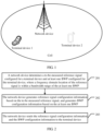
- FIG. 1 is a schematic structural diagram of a system according to an embodiment of this application.
- the system may include a network device and a terminal device, where there may be one or more terminal devices.
- the terminal device in this application may include a handheld device, an in-vehicle device, a wearable device, or a computing device that provides a wireless communication function; another processing device connected to a wireless modem; or user equipment (User equipment, UE) in various forms, including a mobile station (Mobile Station, MS), a terminal (terminal), a terminal device (Terminal Equipment), and the like.
- UE user equipment
- the devices mentioned above are collectively referred to as user equipment or UE.
- the network device in this application may include a base station (base station, BS for short), and the network device is an apparatus deployed in a radio access network to provide the UE with a wireless communication function.
- the base station may include a macro base station, a micro base station, a relay station, an access point, and the like in various forms.
- a device having a base station function may have different names.
- the device is referred to as an evolved NodeB (evolved NodeB, eNB or eNodeB for short) in an LTE system, referred to as a gNB in an NR system, referred to as a NodeB (Node B) in a 3rd generation 3G system, or the like.
- FIG. 2 shows an embodiment of a reference signal processing method in this application. The method may include the following steps.
- the network device determines a to-be-measured reference signal configured for the terminal device and at least one BWP configured for the terminal device, where a frequency domain location of the reference signal is within a bandwidth range of the at least one BWP.
- the network device may configure the reference signal for the terminal device, where the reference signal specifically includes: a synchronization signal (Synchronization Signal, SS) or a channel state information-reference symbol (Channel State Information-Reference Symbol, CSI-RS).
- the SS is a synchronization signal of a cell, and UE may obtain measurement quality of the cell based on measurement of the synchronization signal.
- the CSI-RS is a reference signal configured for UE, and the UE may alternatively obtain quality of a cell based on measurement of the CSI-RS.
- the network device may configure at least one BWP for the terminal device. For example, the network device may configure one BWP for the terminal device, or the network device configures a plurality of BWPs for the terminal device.
- a BWP may be a part of bandwidth of a cell, and the network device may perform such configuration that the terminal device works on the at least one BWP, at least one of the at least one BWP is active, and the active BWP may be used for data transmission between the network device and the terminal device.
- the network device determines the reference signal and the at least one BWP for the terminal device, where the frequency domain location of the reference signal is within the bandwidth range of the at least one BWP.
- the bandwidth range of the at least one BWP includes a sending frequency domain location of the reference signal.
- the network device generates reference signal configuration information based on the to-be-measured reference signal, and generates BWP configuration information based on the at least one BWP.
- the network device may generate the reference signal configuration information based on the determined reference signal, where the reference signal configuration information includes information about the reference signal configured by the network device for the terminal device.
- the network device may further generate the BWP configuration information based on the determined at least one BWP, where the BWP configuration information includes information of the BWP configured by the network device for the terminal device.
- the reference signal configuration information generated by the network device for the terminal device includes at least one of the following parameters: a type parameter of the reference signal, a period parameter of the reference signal, and a frequency domain location parameter of the reference signal.
- the type parameter of the reference signal may indicate that the reference signal is an SS or a CSI-RS
- the period parameter of the reference signal is used to indicate a sending period of the reference signal
- the frequency domain location parameter of the reference signal is used to indicate a frequency domain location at which the reference signal is sent to the terminal device.
- the BWP configuration information generated by the network device for the terminal device includes: frequency information of the at least one BWP and bandwidth information of the at least one BWP.
- the BWP configured by the network device for the terminal device may be indicated by a frequency and bandwidth of the BWP.
- the network device may configure a BWP set for the terminal device, and the BWP set includes one or more pieces of BWP configuration information.
- the at least one BWP includes a corresponding reference signal, and the reference signal is an SS or a CSI-RS.
- the BWP configuration information generated by the network device includes a correspondence between the reference signal and the at least one BWP.
- the network device may indicate a correspondence between a reference signal and at least one BWP to the terminal device by using the BWP configuration information. Therefore, the terminal device may determine, based on the BWP configuration information, a reference signal corresponding to each BWP.
- the BWP configuration information generated by the network device may further include activation time information of the BWP.
- the activation time information of the BWP may include at least one of the following parameters: an activation time period of the at least one BWP and an activation time offset of the at least one BWP.
- An activation time of the BWP occurs based on the activation time period, and the activation time offset is an offset of the activation time of the BWP.
- the activation time period and the activation time offset may be used to calculate activation duration of the BWP each time.
- the network device sends the reference signal configuration information and the BWP configuration information to the terminal device.
- the network device may send the reference signal configuration information and the BWP configuration information to the terminal device, so that the terminal device may receive the reference signal configuration information and the BWP configuration information from the network device.
- the terminal device After parsing the reference signal configuration information and the BWP configuration information, the terminal device can determine content of the reference signal and content of the BWP that are configured by the network device.
- the network device may add the reference signal configuration information and the BWP configuration information to same control signaling, and send the control signaling to the terminal device.
- the network device may add the reference signal configuration information and the BWP configuration information to two different pieces of control signaling respectively, and send the control signaling to the terminal device.
- the control signaling used by the network device may be higher layer signaling.
- the reference signal processing method provided in this embodiment of this application may include the following steps:
- the network device may further configure the first gap used by the network device to send the reference signal, where the first gap may be a gap that occurs periodically.
- the network device may configure the period of the first gap and the offset of the first gap.
- the first gap may occur based on a time period, and the offset of the first gap is an offset of an occurrence time of the first gap.
- the period of the first gap and the offset of the first gap may be used to calculate duration of the first gap each time.
- the network device may further send the gap configuration information to the terminal device, so that the terminal device may receive the gap configuration information from the network device. After parsing the gap configuration information, the terminal device can determine the period and the offset that are configured by the network device for the first gap.
- the reference signal processing method provided in this embodiment of this application may include the following steps:
- the deactivating the first gap may include: skipping starting, in the duration corresponding to the first gap, an operation performed by the terminal device during the measurement gap, and normally performing a data receiving and sending operation on a current serving cell.
- the first gap occurs periodically, and the period and the offset of the first gap can be used together to calculate time information of the first gap.
- a frame that satisfies the system frame number (System Frame Number, SFN) 1 in formula 1 may be determined as a frame of the first gap.
- SFN represents a frame number at which a measurement gap starts. Because the time information of the first gap is calculated, SFN 1 represents a start frame number of the first gap. T1 represents a period of the first gap, gapOffset represents an offset of the first gap, FLOOR() represents a round-down operation, and mod represents a modulo operation, that is, a remainder operation.
- Formula 1 is used to calculate the start frame number of the first gap. To make a calculation result more accurate to obtain a location of a start subframe, the following formula may also be used in this embodiment of this application:
- Subframe 1 gapOffset mod 10 (Formula 2)
- subframe 1 represents a start subframe number of the first gap. Therefore, by using formula 1 and formula 2, the network device may calculate the start frame number and subframe numbers of the first gap, thereby determining the start time of the first gap more accurately.
- the network device may further calculate the duration of the first gap based on the start time of the first gap and the length of the first gap. For example, the network device determines the duration of the first gap based on the start time of the first gap and the time length of the first gap, where the length of the first gap may be a fixed length, for example, 6 milliseconds (ms), or a length configured by the network device, for example, 3 ms.
- the length of the first gap may be a fixed length, for example, 6 milliseconds (ms), or a length configured by the network device, for example, 3 ms.
- the network device may determine whether the frequency domain location of the reference signal is within the bandwidth range of the active BWP in the duration of the first gap, and if the frequency domain location of the reference signal is within the bandwidth range of the active BWP in the duration of the first gap, the network device determines to deactivate the first gap. If the first gap is deactivated, the first gap does not need to be restarted, thereby reducing a slot start time.
- the reference signal processing method provided in this embodiment of this application may include the following steps:
- the network device may also activate the BWP for the terminal device, and the network device sends the activation time information of the BWP to the terminal device.
- the activation time information of the BWP may include at least one of the following parameters: an activation time period of the at least one BWP and an activation time offset of the at least one BWP.
- An activation time of the at least one BWP occurs periodically, and the activation time period and the activation time offset can be used together to calculate the activation time of the at least one BWP.
- a frame in which the activation time of the BWP occurs can be determined by using SFN 2.
- SFN 2 represents the start frame number of the activation time
- T2 represents the activation time period
- the activation time offset is represented by timeoffset
- FLOOR() represents a round-down operation
- mod represents a modulo operation, that is, a remainder operation.
- Formula 3 is used to calculate the start frame number of the activation time. To make a calculation result more accurate to obtain a location of a start subframe, the following formula 4 may also be used in this embodiment of this application:
- Subframe 2 timeoffset mod 10 (Formula 4)
- subframe 2 represents a start subframe number of the activation time of the BWP. Therefore, by using formula 3 and formula 4, the start frame number and the start subframe number that are of the activation time of the BWP can be calculated, thereby determining activation time information of the BWP more accurately.
- the BWP configuration information may further include information about the activation time length of the at least one BWP.
- the network device may determine the activation duration of the at least one BWP based on the start time of the at least one BWP and the activation time length of the at least one BWP, where the activation duration of the at least one BWP is used for the data transmission between the network device and the terminal device.
- the network device determines the to-be-measured reference signal configured for the terminal device and the at least one BWP configured for the terminal device, where the frequency domain location of the reference signal is within the bandwidth range of the at least one BWP; the network device generates the reference signal configuration information based on the to-be-measured reference signal, and generates the BWP configuration information based on the at least one BWP; and the network device sends the reference signal configuration information and the BWP configuration information to the terminal device.
- the network device may send the reference signal configuration information and the BWP configuration information to the terminal device, so that the terminal device may parse the reference signal configuration information and the BWP configuration information, and obtain quality of a cell based on the reference signal. Therefore, in this embodiment of this application, the reference signal can be measured without starting a measurement gap, thereby reducing activation of the measurement gap and reducing data receiving and sending of the terminal device.
- an embodiment of this application provides a reference signal processing method, mainly including the following steps.
- a terminal device obtains reference signal configuration information and bandwidth part BWP configuration information that are sent by a network device.
- the network device may send the reference signal configuration information and the BWP configuration information to the terminal device, and the terminal device may receive the reference signal configuration information and the BWP configuration information from the network device.
- the terminal device may receive the reference signal configuration information and the BWP configuration information by using a wireless network.
- the network device may add the reference signal configuration information and the BWP configuration information to same control signaling, and send the control signaling to the terminal device.
- the network device may add the reference signal configuration information and the BWP configuration information to two different pieces of control signaling respectively, and send the control signaling to the terminal device. No limitation is imposed herein.
- the control signaling used by the network device may be higher layer signaling.
- the terminal device determines a to-be-measured reference signal based on the reference signal configuration information, and determines, based on the BWP configuration information, a BWP configured for the terminal device.
- the terminal device may parse the reference signal configuration information and the BWP configuration information, and the terminal device may determine content of the reference signal and content of the BWP that are configured by the network device. For example, the terminal device determines, by parsing the reference signal configuration information, the to-be-measured reference signal configured by the network device for the terminal device, and the terminal device determines, by parsing the BWP configuration information, the BWP configured by the network device for the terminal device.
- the terminal device obtains quality of a cell based on the reference signal, where the BWP configured for the terminal device belongs to the cell.
- the terminal device may determine, by performing the foregoing step 302, the BWP configured by the network device for the terminal device, and the terminal device may further determine the configuration of the reference signal by the network device. Therefore, the terminal device may obtain the quality of the cell based on the reference signal.
- the cell may include the BWP configured for the terminal device. Measurement of the quality of the cell may be performed by receiving the reference signal through an antenna of the terminal device and then calculating by using a processor of the terminal device.
- the reference signal processing method provided in this embodiment of this application may include the following steps:
- the network device may further configure the first gap used by the network device to send the reference signal, where the first gap may be a gap that occurs periodically.
- the network device may configure the period of the first gap and the offset of the first gap.
- the first gap may occur based on a time period, and the offset of the first gap is an offset of an occurrence time of the first gap.
- the period of the first gap and the offset of the first gap may be used to calculate duration of the first gap each time.
- the terminal device may receive the gap configuration information from the network device. After parsing the gap configuration information, the terminal device can determine the period and the offset that are configured by the network device for the first gap.
- the first gap occurs periodically, and the period and the offset of the first gap can be used together to calculate time information of the first gap.
- a frame that satisfies the system frame number (System Frame Number, SFN) 1 in formula 1 may be determined as a frame of the first gap.
- SFN represents a frame number at which a measurement gap starts. Because the time information of the first gap is calculated, SFN 1 represents a start frame number of the first gap. T1 represents a period of the first gap, gapOffset represents an offset of the first gap, FLOOR() represents a round-down operation, and mod represents a modulo operation, that is, a remainder operation.
- Formula 1 is used to calculate the start frame number of the first gap. To make a calculation result more accurate to obtain a location of a start subframe, the following formula may also be used in this embodiment of this application:
- Subframe 1 gapOffset mod 10 (Formula 2)
- subframe 1 represents a start subframe number of the first gap. Therefore, by using formula 1 and formula 2, the terminal device may calculate the start frame number and subframe numbers of the first gap, thereby determining the start time of the first gap more accurately.
- the terminal device may further calculate the duration of the first gap based on the start time of the first gap and the length of the first gap. For example, the terminal device determines the duration of the first gap based on the start time of the first gap and the time length of the first gap, where the length of the first gap may be a fixed length, for example, 6 milliseconds (ms), or a length configured by the network device for the terminal device, for example, 3 ms.
- ms milliseconds
- the obtaining, by the terminal device, quality of a cell based on the reference signal in step 303 includes:
- the terminal device may first determine the BWP activated by the network device, and then after the terminal device calculates the duration of the first gap by performing the foregoing steps, the terminal device determines whether the frequency domain location of the reference signal is within the bandwidth range of the active BWP. If the frequency domain location of the reference signal is within the bandwidth range of the active BWP, it indicates that the terminal device can obtain, without using the first gap, the quality of the cell corresponding to the reference signal. In this case, the terminal device may deactivate the first gap. In this embodiment of this application, the terminal device may determine the active BWP, thereby reducing a gap start time. Therefore, a data transmission interruption between the network device and the terminal device is reduced.
- the method provided in this embodiment of this application further includes the following step: if the frequency domain location of the reference signal is not within the bandwidth range of the active BWP, activating, by the terminal device, the first gap, and obtaining the quality of the cell that is in the activated first gap and that corresponds to the reference signal.
- the terminal device may obtain the quality of the cell that is in the activated first gap and that corresponds to the reference signal. In this embodiment of this application, the terminal device may activate the first gap, thereby obtaining the quality of the cell in the first gap.
- the BWP configuration information further includes activation time information of the BWP
- the activation time information of the BWP includes an activation time period of the BWP configured for the terminal device and an activation time offset of the BWP configured for the terminal device.
- the network device may also activate the BWP for the terminal device, and the terminal device receives the activation time information of the BWP from the network device.
- the activation time information of the BWP may include at least one of the following parameters: an activation time period of the at least one BWP and an activation time offset of the at least one BWP.
- An activation time of the at least one BWP occurs periodically, and the activation time period and the activation time offset can be used together to calculate the activation time of the at least one BWP.
- a frame in which the activation time of the BWP occurs can be determined by using SFN 2.
- SFN 2 represents the start frame number of the activation time
- T2 represents the activation time period
- the activation time offset is represented by timeoffset
- FLOOR() represents a round-down operation
- mod represents a modulo operation, that is, a remainder operation.
- Formula 3 is used to calculate the start frame number of the activation time. To make a calculation result more accurate to obtain a location of a start subframe, the following formula 4 may also be used in this embodiment of this application:
- Subframe 2 timeoffset mod 10 (Formula 4)
- subframe 2 represents a start subframe number of the activation time of the BWP. Therefore, by using formula 3 and formula 4, the start frame number and the start subframe number that are of the activation time of the BWP can be calculated, thereby determining activation time information of the BWP more accurately.
- the activation time length is included in the activation time information of the BWP, or the activation time length is locally configured by the terminal device.
- the BWP configuration information may further include information about the activation time length of the at least one BWP.
- the terminal device may determine the activation duration of the at least one BWP based on the start time of the at least one BWP and the activation time length of the at least one BWP, where the activation duration of the at least one BWP is used for data transmission between the terminal device and the network device.
- the BWP configuration information further includes: a quantity of BWPs is N, N is greater than or equal to 2, and bandwidth of each of the N BWPs includes a configured to-be-measured reference signal; and the obtaining, by the terminal device, quality of a cell based on the reference signal, where the BWP configured for the terminal device belongs to the cell in step 303 includes:
- the terminal device may obtain measurement sampling values of different reference signals.
- the terminal device may obtain, in the measurement period, a plurality of sampling results of reference signals corresponding to a plurality of BWPs, and the terminal device may use the sampling results of the plurality of BWPs as the quality of the cell. Therefore, the terminal device can implement measurement of the quality of the cell without starting the gap.
- the calculating, by the terminal device, the quality of the cell based on the M sampling results in step 303 includes:
- the terminal device obtains a plurality of sampling results, for example, obtains M sampling results.
- the terminal device may further select H sampling results from the M sampling results, and the selected sampling results may be sampling results corresponding to the default BWP or the initial BWP.
- the default BWP is a BWP returned by the terminal device within a particular period of time after the data transmission ends
- the initial BWP is a BWP used when the terminal device is in initial access.
- the quality of the cell calculated based on the H sampling results corresponding to the default BWP or the initial BWP, can better indicate real signal quality of a serving cell, thereby improving calculation accuracy of the quality of the cell.
- the terminal device obtains the reference signal configuration information and the BWP configuration information that are sent by the network device; the terminal device determines the to-be-measured reference signal based on the reference signal configuration information, and determines, based on the BWP configuration information, the BWP configured for the terminal device; and the terminal device obtains the quality of the cell based on the reference signal, where the BWP configured for the terminal device belongs to the cell. Because the terminal device can parse the reference signal configuration information and the BWP configuration information, the terminal device can obtain the quality of the cell based on the reference signal. Therefore, in this embodiment of this application, the reference signal can be measured without starting a measurement gap, thereby reducing activation of the measurement gap and reducing data receiving and sending of the terminal device.
- FIG. 4 is a schematic diagram of a BWP implementation according to an embodiment of this application.
- a reference signal sent by a network device may be specifically an SS.
- One SS set periodicity includes a plurality of synchronization signal bursts (SS burst), and each synchronization signal burst includes a plurality of synchronization signal blocks (SS block).
- SS burst synchronization signal burst
- SS block synchronization signal blocks
- one cell may include a plurality of BWPs, for example, a BWP 1 and a BWP 2. It is possible that each BWP is configured with an SS, or it is possible that only some of the BWPs are configured with SSs.
- the reference signal processing method provided in this embodiment of this application may avoid or reduce a measurement gap (which may also be referred to as a GAP in subsequent embodiments).
- a measurement gap which may also be referred to as a GAP in subsequent embodiments.
- a terminal device determines, based on an active BWP, whether a gap needs to be started. For specific content, refer to an embodiment shown in FIG. 5 . 2 .
- the network device configures a periodic activation time period of the BWP, and the terminal device performs measurement in this time period to avoid starting of the gap.
- FIG. 6 . 3 refer to an embodiment shown in FIG. 6 . 3 .
- the terminal device performs measurement by using reference signals of a plurality of active BWPs to avoid starting of the gap.
- FIG. 7 For specific content, refer to an embodiment shown in FIG. 7 .
- FIG. 5 is a schematic diagram of a reference signal configuration manner according to an embodiment of the present invention.
- the configuration manner may mainly include the following process.
- Step 10 A network device sends BWP configuration information and to-be-measured reference signal configuration information to a terminal device.
- the terminal device receives a BWP set configured by the network device, and the BWP set includes one or more pieces of BWP configuration information. At least one BWP includes a corresponding reference signal.
- the reference signal is an SS or a CSI-RS.
- the to-be-measured reference signal information may be an SS or a CSI-RS.
- the reference information configuration information may be a reference information type, such as an SS or a CSI-RS.
- the reference signal configuration information may further include a period and/or a frequency domain location of the reference signal.
- Step 20 The network device configures a gap parameter for the terminal device, where the gap parameter is used to assist the terminal device in measurement of the reference signal.
- the gap parameter may include period information of a gap, and an offset of the gap.
- the gap occurs periodically, and a location of the gap can be calculated based on the offset and the period of the gap together. For example, it is shown in formula 1 and formula 2 in the foregoing embodiment. Details are not described herein again.
- the terminal device determines the time location of the gap based on a calculated gap start time and gap length information.
- the gap length information may be a fixed length, for example, 6 ms, or a length configured by the network for the terminal device, for example, 3 ms.
- the terminal device determines, based on the time location of the gap, that at the time location, the terminal stops data receiving and sending for a serving cell or an active BWP, and measures a target reference signal in this period of time.
- the gap parameter further includes reference signal association information corresponding to the gap, to instruct the terminal device to measure, in the gap, reference information associated with the reference signal association information.
- the reference signal association information may be specifically frequency information.
- the reference information associated with the reference signal association information may be a reference signal included in the frequency.
- Step 30 The terminal device receives the gap parameter, and obtains quality of a cell based on the gap parameter and the active BWP.
- the terminal device needs to determine whether it is necessary to interrupt receiving and sending for the serving cell or the active BWP at the time location of the gap. If at the time location of the gap, the active BWP of the terminal device and to-be-measured reference information meet a first predetermined condition, the terminal device determines to deactivate the gap, that is, the data receiving and sending for the serving cell or the active BWP does not need to be interrupted. Otherwise, the terminal device determines that the gap needs to be activated, that is, the data receiving and sending for the serving cell or the active BWP needs to be interrupted.
- the first predetermined condition includes: a frequency domain location of the to-be-measured reference signal is included in bandwidth of the active BWP; center frequencies of the active BWP and the to-be-measured reference signal are the same; and subcarrier spacings of the active BWP and the to-be-measured reference signal are the same.
- the foregoing determining is performed only when the to-be-measured reference signal belongs to reference signals associated with the gap.
- the gap may be configured to measure only some measurement objects, and reference signals included in these measurement objects may be considered as reference signals associated with the gap. If the gap needs to be activated, the terminal device activates the gap, and measurement of a measurement signal that belongs to the gap is performed in the gap to obtain the quality of the cell. If the gap does not need to be activated, the terminal device directly obtains the quality of the cell.
- the terminal device further determines the active BWP, thereby reducing a GAP start time.
- FIG. 6 is a schematic diagram of another reference signal configuration manner according to an embodiment of the present invention.
- the configuration manner mainly includes the following steps.
- Step 20 A network device configures BWP configuration information and periodic activation time information for a terminal device.
- the terminal device receives a BWP set configured by the network device, and the BWP set includes one or more pieces of BWP configuration information.
- a frequency band of at least one BWP includes a to-be-measured reference signal.
- the reference signal is an SS or a CSI-RS.
- the network device further configures the periodic activation time information for the at least one BWP.
- the periodic activation time information may include: period information of an activation time and an offset of the activation time.
- the activation time occurs periodically, and a location of the activation time can be calculated based on the period and the offset of the activation time together.
- a specific calculation process is shown in formula 3 and formula 4 in the foregoing embodiments.
- the BWP configuration information further includes information about the activation time length of the at least one BWP.
- Step 21 The terminal device needs to activate the BWP at the activation time of the at least one BWP, and obtain quality of a cell of a reference signal included in the BWP.
- the terminal device calculates a start time point of the BWP based on the configuration information, and determines the activation time length of the BWP.
- the activation time length may be a predefined time length, or may be an activation time length carried in the configuration information.
- the terminal device obtains, within the activation time length, the quality of the cell corresponding to the reference information.
- a periodic activation time of the BWP is configured, thereby ensuring a measurement time of the terminal device in the BWP.
- FIG. 7 is a schematic diagram of still another reference signal configuration manner according to an embodiment of the present invention.
- the configuration manner mainly includes the following process.
- Step 30 A network device sends BWP configuration information and to-be-measured reference signal configuration information to a terminal device.
- Step 31 The terminal device receives a BWP set configured by the network device, and the BWP set includes one or more pieces of BWP configuration information.
- At least one BWP includes a corresponding reference signal.
- the reference signal is an SS or a CSI-RS.
- the to-be-measured reference signal information may be an SS or a CSI-RS.
- the reference information configuration information may be a reference information type, such as an SS or a CSI-RS.
- the reference signal configuration information may further include a period and/or a frequency domain location of the reference signal.
- Step 32 The terminal device obtains quality of a cell based on the reference signal configuration.
- the terminal device receives a BWP set configured by the network device, and the BWP set includes one or more pieces of BWP configuration information.
- each BWP includes a corresponding reference signal
- the terminal device obtains the quality of the cell based on reference signals of a plurality of BWPs.
- the reference signal is an SS or a CSI-RS.
- the terminal device obtains a sampling result based on a reference signal included in an active BWP. If the terminal device has a plurality of active BWPs in a measurement period, there may be measurement samples of a plurality of BWPs. The terminal device obtains the quality of the cell based on these samples. The terminal device may have N sampling values in this period. If M sampling values are needed to calculate the quality of the cell, and M is less than or equal to N, M may be selected from N according to the following rules: default BWP and initial BWP sampling preference. A default BWP is configured by the network for the terminal device, and an initial BWP is a BWP used when the terminal device is in initial access.
- the terminal device performs average calculation on selected sampling results to obtain the quality of the cell.
- the terminal device performs average calculation on these measurement results and uses the average result as the quality of the cell in this period.
- This embodiment of this application may further resolve the following problem: In combination with a blacklist and a whitelist that correspond to a measurement event and a blacklist and a whitelist that are of a measurement object level, a BWP or a neighboring cell reference signal that needs to be measured by the terminal device and that is included in a serving cell is determined.
- a measurement event configuration BWP indication is used to determine that the measurement event is for the BWP in the serving cell.
- the network device may specify a measurement quantity for beam selection when cell measurement result calculation and beam reporting are performed.
- FIG. 8 is a schematic diagram of yet another reference signal configuration manner according to an embodiment of the present invention.
- the configuration manner mainly includes the following process.
- Step 40 A network device configures to-be-measured reference signal configuration information for a terminal device.
- the to-be-measured reference signal information may be an SS or a CSI-RS.
- the to-be-measured reference information configuration information is included in a measurement object, and a measurement object configuration may include at least one or a combination of the following configurations, for example:
- the network device further configures a measurement evaluation parameter for the terminal device, where the measurement evaluation parameter includes at least one or a combination of the following configuration information:
- the measurement quantity (Q) for beam sorting, the measurement quantity (T) for triggering a measurement event, and the measurement quantity (M) that needs to be reported are not limited to being configured in the measurement object, and may alternatively be sent, by the network device through measurement configuration, to the terminal device to which Q, T, and M belong.
- Q, T, and M are carried in a measurement and reporting configuration, a measurement quantity configuration, or a measurement trigger configuration. No limitation is imposed in the present invention.
- Step 41 The network device configures measurement trigger information for the terminal device, where the measurement trigger information includes event trigger information or periodic measurement configuration information, the event trigger information is used to instruct the terminal device to trigger measurement and reporting based on a to-be-measured reference signal, and the periodic measurement configuration is used to instruct the terminal device to perform measurement and reporting based on a period.
- the measurement trigger information includes event trigger information or periodic measurement configuration information
- the event trigger information is used to instruct the terminal device to trigger measurement and reporting based on a to-be-measured reference signal
- the periodic measurement configuration is used to instruct the terminal device to perform measurement and reporting based on a period.
- the measurement event is used for comparing a measurement target and a measurement reference. When a comparison result satisfies a predetermined condition, it is determined that the measurement result needs to be reported.
- the measurement target may be a serving cell or a neighboring cell.
- the measurement reference may be a measurement signal threshold or a measurement result on a serving cell side.
- the terminal device needs to first determine the measurement result of the cell corresponding to the measurement target and then determine whether the measurement event is triggered. For example, if the measurement target is a cell included in a measurement object 1, the terminal device searches for the cell on a frequency corresponding to the measurement object 1, and compares the cell measurement result with the measurement reference. If the cell measurement result is greater than or less than the measurement reference, measurement event reporting is triggered.
- the event trigger information further includes a blacklist or a whitelist for the measurement event.
- Step 42 The terminal device receives the measurement configuration information, where the measurement configuration information includes the reference signal configuration, the measurement evaluation parameter, and the measurement trigger information, and the terminal device performs measurement and reporting based on the reference signal configuration, the measurement evaluation parameter, and the measurement trigger information.
- the terminal device determines one or a combination of the following parameters based on the measurement configuration information:
- the terminal device performs measurement and reporting based on the measurement configuration parameter.
- to-be-measured cells need to be determined based on the blacklist or whitelist included in the measurement object. If a configuration of the measurement event includes configuration of the blacklist or the whitelist, the terminal device needs to finally determine, based on the blacklist or whitelist in the measurement object and the blacklist or whitelist in the measurement event, a blacklist or whitelist cell to be used.
- the measurement event includes a whitelist
- a whitelist in the measurement object is ignored, and only a whitelist specified by the measurement event is used.
- the measurement event includes a blacklist
- a blacklist in the measurement object and a blacklist in the measurement event are combined for use.
- the terminal device performs measurement based on the finally determined blacklist or whitelist, obtains quality of a cell corresponding to the measurement target, and determines whether to trigger the measurement event based on comparison between the quality of the cell and a measurement source.
- blacklists and whitelists there may be different blacklists and whitelists.
- an event 1 may be only for a reference signal that is not of a local cell
- an event 2 may be only for a reference signal of the local cell.
- the cell measurement result needs to be calculated based on beams of the cell.
- the terminal device first performs cell measurement result calculation based on the parameters configured by the network device, including: determining, by the terminal device based on N, H, and Q, beams used to calculate the cell measurement result.
- the terminal device sorts the beams in the cell based on a measurement quantity (for example, the RSRQ, the RSRP, or the SINR) specified by Q.
- a measurement quantity for example, the RSRQ, the RSRP, or the SINR
- the beam ranked first is used as a first beam, and beams whose measurement results are greater than the threshold H and whose total quantity is less than or equal to (N-1) are selected from the other beams as a second beam set.
- the cell measurement result is calculated by using the second beam set based on a quantity (for example, one or any combination of the RSRQ, the RSRP, or the SINR) specified in a report quantity.
- a quantity for example, one or any combination of the RSRQ, the RSRP, or the SINR
- N 1, the measurement result of the first beam is used as the quality of the cell. If N > 1, the first beam and the second beam set are averaged as the quality of the cell.
- the terminal device when reporting a measurement result, needs to determine a set of to-be-reported beams.
- the terminal device sorts the beams in the cell based on a measurement quantity (for example, the RSRQ, the RSRP, or the SINR) specified by Q or T, and reports the beam set based on a sorting result.
- a measurement quantity for example, the RSRQ, the RSRP, or the SINR
- the terminal device determines to report, based on the threshold H and a maximum quantity X of reported beams, beams that are greater than the threshold H and whose quantity is less than or equal to X.
- X is a reporting quantity specified by the network device for the terminal device.
- the terminal device reports, to a network device side, a measurement result corresponding to each beam.
- the terminal device first adds, based on a measurement quantity specified by the reported measurement quantity (M), a best beam corresponding to each measurement quantity to the set of the reported beams, and then sorts the remaining beams based on the measurement quantity specified by Q or T, and determines, based on a sorting result, beams that are in the remaining beams and that are to be placed in the set of the reported beams.
- M reported measurement quantity
- Q or T the measurement quantity specified by Q or T
- the terminal device sorts the beams in the cell based on the measurement quantity (for example, the RSRQ, the RSRP, or the SINR) specified by Q or T may further include: selecting, by the terminal device, T and Q based on a measurement trigger type. For example, for an event measurement result, the terminal device sorts to-be-reported beams based on T, and for periodic measurement, the terminal device sorts to-be-reported beams based on Q.
- the measurement quantity for example, the RSRQ, the RSRP, or the SINR
- the terminal device sorts the beams in the cell based on a configuration of the reported measurement quantity (M). If the terminal device determines that the measurement quantity M includes only one measurement quantity, the terminal device performs beam sorting based on the measurement quantity, and based on a beam sorting result, calculates the quality of the cell or determines a to-be-reported beam set.
- M reported measurement quantity
- a measurement quantity used for beam sorting is specified, thereby ensuring that the terminal device has a consistent sorting criterion during beam sorting.
- a blacklist and a whitelist are configured for a measurement event, so that different measurement events may be configured with different blacklists and whitelists.
- FIG. 9 shows a network device 900 according to an embodiment of this application.
- the network device 900 may include a processing module 901 and a sending module 902.
- the processing module 901 is configured to determine a to-be-measured reference signal configured for a terminal device and at least one bandwidth part BWP configured for the terminal device, where a frequency domain location of the reference signal is within a bandwidth range of the at least one BWP.
- the processing module 901 is further configured to generate reference signal configuration information based on the to-be-measured reference signal, and generate BWP configuration information based on the at least one BWP.
- the sending module 902 is configured to send the reference signal configuration information and the BWP configuration information to the terminal device.
- the processing module 901 is further configured to determine a period of a first gap and an offset of the first gap that are configured for the terminal device, where the first gap is used by the network device to send the reference signal.
- the sending module 902 is further configured to send gap configuration information to the terminal device, where the gap configuration information includes the period of the first gap and the offset of the first gap.
- the processing module 901 is configured to: calculate a start time of the first gap based on the period of the first gap and the offset of the first gap; calculate duration of the first gap based on the start time of the first gap and a length of the first gap; determine whether the frequency domain location of the reference signal is within a bandwidth range of an active BWP in the duration of the first gap; and if the frequency domain location of the reference signal is within the bandwidth range of the active BWP in the duration of the first gap, determine to deactivate the first gap.
- the reference signal configuration information includes at least one of the following parameters: a type parameter of the reference signal, a period parameter of the reference signal, and a frequency domain location parameter of the reference signal.
- the BWP configuration information includes: frequency information of the at least one BWP and bandwidth information of the at least one BWP.
- the BWP configuration information includes a correspondence between the reference signal and the at least one BWP.
- the BWP configuration information includes activation time information of the BWP; and the activation time information of the BWP includes at least one of the following parameters: an activation time period of the at least one BWP and an activation time offset of the at least one BWP.
- the processing module 901 is configured to calculate a start time of the at least one BWP based on the activation time period of the at least one BWP and the activation time offset of the at least one BWP.
- the processing module 901 is further configured to determine activation duration of the at least one BWP based on the start time of the at least one BWP and an activation time length of the at least one BWP, where the activation duration of the at least one BWP is used for data transmission between the network device and the terminal device.
- FIG. 10 shows a terminal device 1000 according to an embodiment of this application.
- the terminal device 1000 may include a receiving module 1001 and a processing module 1002.
- the receiving module 1001 is configured to obtain reference signal configuration information and bandwidth part BWP configuration information that are sent by a network device.
- the processing module 1002 is configured to determine a to-be-measured reference signal based on the reference signal configuration information, and determine, based on the BWP configuration information, a BWP configured for the terminal device.
- the processing module 1002 is configured to obtain quality of a cell based on the reference signal, where the BWP configured for the terminal device belongs to the cell.
- the receiving module 1001 is further configured to obtain gap configuration information sent by the network device, where the gap configuration information includes period information of a first gap and offset information of the first gap.
- the processing module 1002 is further configured to determine duration of the first gap based on the period information of the first gap and the offset information of the first gap.
- the processing module 1002 is configured to: determine an active BWP, where the active BWP is one or more BWPs in BWPs configured for the terminal device; after the terminal device determines the duration of the first gap, determine whether a frequency domain location of the reference signal is within a bandwidth range of the active BWP; and if the frequency domain location of the reference signal is within the bandwidth range of the active BWP, deactivate the first gap, and obtain the quality of the cell based on the reference signal corresponding to the active BWP.
- the processing module 1002 is configured to: if the frequency domain location of the reference signal is not within the bandwidth range of the active BWP, activate the first gap; and obtain the quality of the cell that is in the activated first gap and that corresponds to the reference signal.
- the BWP configuration information further includes activation time information of the BWP
- the activation time information of the BWP includes an activation time period of the BWP configured for the terminal device and an activation time offset of the BWP configured for the terminal device.
- the processing module 1002 is configured to: determine, based on the activation time period of the BWP configured for the terminal device and the activation time offset of the BWP configured for the terminal device, a start time of the BWP configured for the terminal device; and obtain, from the start time of the BWP configured for the terminal device, the quality of the cell that is in an activation time length configured for the terminal device and that corresponds to the reference signal.
- the activation time length is included in the activation time information of the BWP, or the activation time length is locally configured by the terminal device.
- the BWP configuration information further includes: when a quantity of BWPs is N and N is greater than or equal to 2, bandwidth of each of the N BWPs includes a configured to-be-measured reference signal.
- the processing module 1002 is specifically configured to: obtain, in a measurement period, M sampling results corresponding to a reference signal within a bandwidth range of a BWP activated at a sampling moment, where M is a positive integer; and calculate the quality of the cell based on the M sampling results.
- the processing module 1002 is specifically configured to: extract H sampling results from the M sampling results, where H is less than M, the H sampling results are sampling results obtained by sampling a reference signal corresponding to a first BWP, and the first BWP is a default BWP or an initial BWP; and calculate the quality of the cell based on the H sampling results.
- the terminal device obtains the reference signal configuration information and the BWP configuration information that are sent by the network device; the terminal device determines the to-be-measured reference signal based on the reference signal configuration information, and determines, based on the BWP configuration information, the BWP configured for the terminal device; and the terminal device obtains the quality of the cell based on the reference signal, where the BWP configured for the terminal device belongs to the cell. Because the terminal device can parse the reference signal configuration information and the BWP configuration information, the terminal device can obtain, based on the BWP configured for the terminal device, the quality of the cell corresponding to the reference signal. Therefore, in this embodiment of this application, the reference signal can be measured without starting a measurement gap, thereby reducing activation of the measurement gap and reducing data receiving and sending of the terminal device.
- An embodiment of this application further provides a computer storage medium, where the computer storage medium stores a program and the program performs some or all of steps recorded in the foregoing method embodiments.
- the network device 1100 includes: a receiver 1101, a transmitter 1102, a processor 1103, and a memory 1104 (where there may be one or more processors 1103 in the network device 1100, and one processor is used as an example in FIG. 11 ).
- the receiver 1101, the transmitter 1102, the processor 1103, and the memory 1104 may be connected with each other.
- the memory 1104 may include a read-only memory and a random access memory, and provide an instruction and data to the processor 1103. A part of the memory 1104 may further include a nonvolatile random access memory (English: Non-Volatile Random Access Memory, NVRAM for short).
- the memory 1104 stores an operating system and operating instructions, and an executable module or a data structure, or a subset or an extended set thereof, where the operating instructions may include various operating instructions and are used to implement various operations.
- the operating system may include various system programs, which are used to implement various basic services and process a hardware-based task.
- the processor 1103 controls operations of the network device.
- the processor 1103 may also be referred to as a central processing unit (English: Central Processing Unit, CPU for short).
- a bus system In addition to a data bus, the bus system may further include a power bus, a control bus, a status signal bus, and the like. However, for clear description, various buses are marked as the bus system in the figure.
- the method disclosed in the foregoing embodiments of this application may be applied to the processor 1103, or implemented by the processor 1103.
- the processor 1103 may be an integrated circuit chip and has a signal processing capability. In an implementation process, the steps of the method may be implemented by integrated logical circuits of hardware in the processor 1103 or by instructions of software.
- the foregoing processor 1103 may be a general-purpose processor, a digital signal processor (English: digital signal processing, DSP for short), an application-specific integrated circuit (English: Application Specific Integrated Circuit, ASIC for short), a field-programmable gate array (English: Field-Programmable Gate Array, FPGA for short) or another programmable logical device, a discrete gate or a transistor logical device, or a discrete hardware assembly.
- the general-purpose processor may be a microprocessor, or the processor may be any conventional processor or the like. Steps of the methods disclosed with reference to the embodiments of this application may be directly executed and accomplished by using a hardware decoding processor, or may be executed and accomplished by using a combination of hardware and software modules in the decoding processor.
- a software module may be located in a mature storage medium in the art, such as a random access memory, a flash memory, a read-only memory, a programmable read-only memory, an electrically erasable programmable memory, a register, or the like. The storage medium is located in the memory 1104, and the processor 1103 reads information in the memory 1104 and completes the steps in the foregoing methods in combination with hardware of the processor.
- the receiver 1101 may be configured to receive input digital or character information, and generate a signal input related to a related setting and functional control of the network device.
- the transmitter 1102 may include a display device, for example, a display screen, and may be configured to output digital or character information by using an external interface.
- the processor 1103 is configured to perform the reference signal processing method performed on a network device side in the foregoing embodiments.
- the terminal device 1200 includes: a receiver 1201, a transmitter 1202, a processor 1203, and a memory 1204 (where there may be one or more processors 1203 in the terminal device 1200, and one processor is used as an example in FIG. 12 ).
- the receiver 1201, the transmitter 1202, the processor 1203, and the memory 1204 may be connected with each other.
- the memory 1204 may include a read-only memory and a random access memory, and provide an instruction and data to the processor 1203. A part of the memory 1204 may further include an NVRAM.
- the memory 1204 stores an operating system and operating instructions, and an executable module or a data structure, or a subset or an extended set thereof, where the operating instructions may include various operating instructions and are used to implement various operations.
- the operating system may include various system programs, which are used to implement various basic services and process a hardware-based task.
- the processor 1203 controls operations of the terminal device, and the processor 1203 may also be referred to as a CPU.
- components of the terminal device are coupled together by using a bus system.
- the bus system may further include a power bus, a control bus, a status signal bus, and the like.
- various buses are marked as the bus system in the figure.
- the method disclosed in the foregoing embodiments of this application may be applied to the processor 1203, or implemented by the processor 1203.
- the processor 1203 may be an integrated circuit chip and has a signal processing capability. In an implementation process, steps in the foregoing methods can be implemented by using a hardware integrated logical circuit in the processor 1203, or by using instructions in a form of software.
- the processor 1203 may be a general-purpose processor, a DSP, an ASIC, an FPGA or another programmable logical device, a discrete gate or a transistor logical device, or a discrete hardware assembly. It may implement or perform the methods, the steps, and logical block diagrams that are disclosed in the embodiments of this application.
- the general-purpose processor may be a microprocessor, or the processor may be any conventional processor or the like. Steps of the methods disclosed with reference to the embodiments of this application may be directly executed and accomplished by using a hardware decoding processor, or may be executed and accomplished by using a combination of hardware and software modules in the decoding processor.
- a software module may be located in a mature storage medium in the art, such as a random access memory, a flash memory, a read-only memory, a programmable read-only memory, an electrically erasable programmable memory, a register, or the like.
- the storage medium is located in the memory 1204, and a processor 1203 reads information in the memory 1204 and completes the steps in the foregoing methods in combination with hardware of the processor.
- the processor 1203 is configured to perform the foregoing method performed on a terminal device side.
- the apparatus when the apparatus is a chip in a terminal, the chip includes a processing unit and a communications unit, where the processing unit may be, for example, a processor, and the communications unit may be, for example, an input/output interface, a pin, or a circuit.
- the processing unit may execute a computer executable instruction stored in a storage unit, to enable the chip in the terminal to perform the wireless communication method according to any one of the possible designs of the first aspect.
- the storage unit may be a storage unit in the chip, such as a register or a buffer, or the storage unit may be a storage unit in the terminal but outside the chip, such as a read-only memory (read-only memory, ROM), another type of static storage device capable of storing static information and instructions, or a random access memory (random access memory, RAM).
- ROM read-only memory
- RAM random access memory
- processors may be a general-purpose central processing unit (CPU), a microprocessor, an application-specific integrated circuit (application-specific integrated circuit, ASIC), or one or more integrated circuits configured to control program execution of the wireless communication method in the first aspect.
- CPU central processing unit
- ASIC application-specific integrated circuit
- connection relationships between modules indicate that the modules have communication connections with each other, which may be specifically implemented as one or more communications buses or signal cables.
- Embodiment 1 A measurement configuration method, comprising:
- Embodiment 2 The method according to embodiment 1, wherein the sorting and reporting, by the terminal device, beams in a cell based on the measurement quantity (M) that needs to be reported or the measurement quantity (T) for triggering a measurement event comprises:
- Embodiment 3 The method according to embodiment 2, wherein the sorting, by the terminal device, the beams in the cell based on the measurement quantity (M) that needs to be reported comprises: if the terminal device determines that the reported measurement quantity comprises only one measurement quantity, performing, by the terminal device, beam sorting based on the measurement quantity, and determining the to-be-reported beam set based on a beam sorting result.
- Embodiment 4 The method according to one of embodiments 1 to 3, wherein the sorting and reporting, by the terminal device, beams in a cell based on the measurement quantity (M) that needs to be reported or the measurement quantity (T) for triggering a measurement event comprises:
- Embodiment 5 The method according to embodiment 4, wherein the sorting, by the terminal device, the beams in the cell based on the measurement quantity (T) for triggering a measurement event comprises: for an event trigger measurement result, sorting, by the terminal device, to-be-reported beams based on the measurement quantity (T) for triggering a measurement event.
- Embodiment 6 The method according to any one of embodiments 1 to 5, wherein the performing measurement and reporting further comprises:
- Embodiment 7 A measurement configuration method, comprising:
- Embodiment 8 The method according to embodiment 7, wherein the reported measurement quantity (M) comprises only one measurement quantity.
- Embodiment 9 The method according to either of embodiments 7 and 8, wherein the reported information comprises information about beams whose measurement quantity is greater than a threshold H and whose quantity is less than or equal to X.
- Embodiment 10 A terminal device, wherein the terminal device comprises: a processor and a memory, wherein
- Embodiment 11 A network device, wherein the network device comprises: a processor and a memory, wherein
- Embodiment 12 A communications system, comprising the terminal device according to embodiment 10 and the network device according to embodiment 11.
- Embodiment 13 A computer readable storage medium, comprising an instruction, wherein when the instruction runs on a computer, the computer performs the method according to any one of embodiments 1 to 6.
- Embodiment 14 A computer readable storage medium, comprising an instruction, wherein when the instruction runs on a computer, the computer performs the method according to any one of embodiments 7 to 9.
- Embodiment 15 A reference signal processing method, comprising:
- Embodiment 16 The method according to embodiment 15, wherein the method further comprises:
- Embodiment 17 The method according to embodiment 16, wherein the method further comprises:
- Embodiment 18 The method according to embodiment 15, wherein the reference signal configuration information comprises at least one of the following parameters: a type parameter of the reference signal, a period parameter of the reference signal, and a frequency domain location parameter of the reference signal.
- Embodiment 19 The method according to embodiment 15, wherein the BWP configuration information comprises: frequency information of the at least one BWP and bandwidth information of the at least one BWP.
- Embodiment 20 The method according to embodiment 15, wherein the BWP configuration information comprises a correspondence between the reference signal and the at least one BWP.
- Embodiment 21 The method according to embodiment 15, wherein the BWP configuration information comprises activation time information of the BWP; and the activation time information of the BWP comprises at least one of the following parameters: an activation time period of the at least one BWP and an activation time offset of the at least one BWP.
- Embodiment 22 The method according to embodiment 21, wherein the method further comprises:
- Embodiment 23 A reference signal processing method, wherein the method comprises:
- Embodiment 24 The method according to embodiment 23, wherein the method further comprises:
- Embodiment 25 The method according to embodiment 24, wherein the obtaining, by the terminal device, quality of a cell based on the reference signal comprises:
- Embodiment 26 The method according to embodiment 25, wherein after the determining, by the terminal device, whether a frequency domain location of the reference signal is within a bandwidth range of the active BWP, the method further comprises: if the frequency domain location of the reference signal is not within the bandwidth range of the active BWP, activating, by the terminal device, the first gap, and obtaining the quality of the cell that is in the activated first gap and that corresponds to the reference signal.
- Embodiment 27 The method according to embodiment 23, wherein the BWP configuration information further comprises activation time information of the BWP, and the activation time information of the BWP comprises an activation time period of the BWP configured for the terminal device and an activation time offset of the BWP configured for the terminal device; and the obtaining, by the terminal device, quality of a cell based on the reference signal comprises:
- Embodiment 28 The method according to embodiment 27, wherein the activation time length is comprised in the activation time information of the BWP, or the activation time length is locally configured by the terminal device.
- Embodiment 29 The method according to embodiment 23, wherein the BWP configuration information further comprises: a quantity of BWPs is N, N is greater than or equal to 2, and bandwidth of each of the N BWPs comprises a configured to-be-measured reference signal; and the obtaining, by the terminal device, quality of a cell based on the reference signal comprises:
- Embodiment 30 The method according to embodiment 29, wherein the calculating, by the terminal device, the quality of the cell based on the M sampling results comprises:
- a network device comprising:
- Embodiment 32 The network device according to embodiment 31, wherein the processing module is further configured to determine a period of a first gap and an offset of the first gap that are configured for the terminal device, wherein the first gap is used by the network device to send the reference signal; and the sending module is further configured to send gap configuration information to the terminal device, wherein the gap configuration information comprises the period of the first gap and the offset of the first gap.
- Embodiment 33 The network device according to embodiment 32, wherein the processing module is configured to: calculate a start time of the first gap based on the period of the first gap and the offset of the first gap; calculate duration of the first gap based on the start time of the first gap and a length of the first gap; determine whether the frequency domain location of the reference signal is within a bandwidth range of an active BWP in the duration of the first gap; and if the frequency domain location of the reference signal is within the bandwidth range of the active BWP in the duration of the first gap, determine to deactivate the first gap.
- Embodiment 34 The network device according to embodiment 31, wherein the reference signal configuration information comprises at least one of the following parameters: a type parameter of the reference signal, a period parameter of the reference signal, and a frequency domain location parameter of the reference signal.
- Embodiment 35 The network device according to embodiment 31, wherein the BWP configuration information comprises: frequency information of the at least one BWP and bandwidth information of the at least one BWP.
- Embodiment 36 The network device according to embodiment 31, wherein the BWP configuration information comprises a correspondence between the reference signal and the at least one BWP.
- Embodiment 37 The network device according to claim 31, wherein the BWP configuration information comprises activation time information of the BWP; and the activation time information of the BWP comprises at least one of the following parameters: an activation time period of the at least one BWP and an activation time offset of the at least one BWP.
- Embodiment 38 The network device according to embodiment 37, wherein the processing module is further configured to calculate a start time of the at least one BWP based on the activation time period of the at least one BWP and the activation time offset of the at least one BWP; and the processing module is further configured to determine activation duration of the at least one BWP based on the start time of the at least one BWP and an activation time length of the at least one BWP, wherein the activation duration of the at least one BWP is used for data transmission between the network device and the terminal device.
- Embodiment 39 A terminal device, wherein the terminal device comprises:
- Embodiment 40 The terminal device according to embodiment 39, wherein the receiving module is further configured to obtain gap configuration information sent by the network device, wherein the gap configuration information comprises period information of a first gap and offset information of the first gap; and the processing module is further configured to determine duration of the first gap based on the period information of the first gap and the offset information of the first gap.
- Embodiment 41 The terminal device according to embodiment 40, wherein the processing module is configured to: determine an active BWP, wherein the active BWP is one or more BWPs in BWPs configured for the terminal device; after the terminal device determines the duration of the first gap, determine whether a frequency domain location of the reference signal is within a bandwidth range of the active BWP; and if the frequency domain location of the reference signal is within the bandwidth range of the active BWP, deactivate the first gap, and obtain the quality of the cell based on the reference signal corresponding to the active BWP.
- Embodiment 42 The terminal device according to embodiment 41, wherein after determining whether the frequency domain location of the reference signal is within the bandwidth range of the active BWP, the processing module is configured to: if the frequency domain location of the reference signal is not within the bandwidth range of the active BWP, activate the first gap; and obtain the quality of the cell that is in the activated first gap and that corresponds to the reference signal.
- Embodiment 43 The terminal device according to embodiment 39, wherein the BWP configuration information further comprises activation time information of the BWP, and the activation time information of the BWP comprises an activation time period of the BWP configured for the terminal device and an activation time offset of the BWP configured for the terminal device; and the processing module is configured to: determine, based on the activation time period of the BWP configured for the terminal device and the activation time offset of the BWP configured for the terminal device, a start time of the BWP configured for the terminal device; and obtain, from the start time of the BWP configured for the terminal device, the quality of the cell that is in an activation time length configured for the terminal device and that corresponds to the reference signal.
- Embodiment 44 The terminal device according to embodiment 43, wherein the activation time length is comprised in the activation time information of the BWP, or the activation time length is locally configured by the terminal device.
- Embodiment 45 The terminal device according to embodiment 39, wherein the BWP configuration information further comprises: a quantity of BWPs is N, N is greater than or equal to 2, and bandwidth of each of the N BWPs comprises a configured to-be-measured reference signal; and the processing module is specifically configured to: obtain, in a measurement period, M sampling results corresponding to a reference signal within a bandwidth range of a BWP activated at a sampling moment, wherein M is a positive integer; and calculate the quality of the cell based on the M sampling results.
- a quantity of BWPs is N, N is greater than or equal to 2
- bandwidth of each of the N BWPs comprises a configured to-be-measured reference signal
- the processing module is specifically configured to: obtain, in a measurement period, M sampling results corresponding to a reference signal within a bandwidth range of a BWP activated at a sampling moment, wherein M is a positive integer; and calculate the quality of the cell based on the M sampling results.
- Embodiment 46 The terminal device according to embodiment 45, wherein the processing module is configured to: extract H sampling results from the M sampling results, wherein H is less than M, the H sampling results are sampling results obtained by sampling a reference signal corresponding to a first BWP, and the first BWP is a default BWP or an initial BWP; and calculate the quality of the cell based on the H sampling results.
- Embodiment 47 A network device, wherein the network device comprises: a processor and a memory, wherein the memory is configured to store an instruction; and the processor is configured to execute the instruction in the memory, so as to perform the method according to any one of embodiments 15 to 22.
- Embodiment 48 A terminal device, wherein the terminal device comprises: a processor and a memory, wherein
- Embodiment 49 A computer readable storage medium, comprising an instruction, wherein when the instruction runs on a computer, the computer performs the method according to any one of embodiments 15 to 22 or embodiments 23 to 30.
- Embodiment 50 A computer program product comprising an instruction, wherein when the instruction runs on a computer, the computer performs the method according to any one of embodiments 15 to 22 or embodiments 23 to 30.
- this application may be implemented by software in addition to necessary general-purpose hardware, or by special-purpose hardware, including a special-purpose integrated circuit, a special-purpose CPU, a special-purpose memory, a special-purpose component, and the like.
- any function that can be performed by a computer program can be easily implemented by using corresponding hardware.
- a specific hardware structure used to achieve a same function may be of various forms, for example, in a form of an analog circuit, a digital circuit, a special-purpose circuit, or the like.
- software program implementation is a better implementation in most cases.
- the technical solutions of this application essentially or the part contributing to the prior art may be implemented in a form of a software product.
- the software product is stored in a readable storage medium, such as a floppy disk, a USB flash drive, a removable hard disk, a read-only memory (ROM, Read-Only Memory), a random access memory (RAM, Random Access Memory), a magnetic disk, or an optical disc of a computer, and includes a plurality of instructions for instructing a computer device (which may be a personal computer, a server, a network device, or the like) to perform the methods described in the embodiments of this application.
- a computer device which may be a personal computer, a server, a network device, or the like
- All or some of the foregoing embodiments may be implemented by using software, hardware, firmware, or any combination thereof.
- the embodiments may be implemented completely or partially in a form of a computer program product.
- the computer program product includes one or more computer instructions.
- the computer may be a general-purpose computer, a special-purpose computer, a computer network, or another programmable apparatus.
- the computer instructions may be stored in a computer readable storage medium or may be transmitted from a computer readable storage medium to another computer readable storage medium.
- the computer instructions may be transmitted from a website, computer, server, or data center to another website, computer, server, or data center in a wired (for example, a coaxial cable, an optical fiber, or a digital subscriber line (DSL)) or wireless (for example, infrared, radio, or microwave) manner.
- a wired for example, a coaxial cable, an optical fiber, or a digital subscriber line (DSL)
- wireless for example, infrared, radio, or microwave
- the computer readable storage medium may be any usable medium accessible by a computer, or a data storage device, such as a server or a data center, integrating one or more usable media.
- the usable medium may be a magnetic medium (for example, a floppy disk, a hard disk, or a magnetic tape), an optical medium (for example, a DVD), a semiconductor medium (for example, a solid-state drive Solid State Disk (SSD)), or the like.
Landscapes
- Engineering & Computer Science (AREA)
- Signal Processing (AREA)
- Computer Networks & Wireless Communication (AREA)
- Quality & Reliability (AREA)
- Physics & Mathematics (AREA)
- Electromagnetism (AREA)
- Mobile Radio Communication Systems (AREA)
- Data Exchanges In Wide-Area Networks (AREA)
- Arrangements For Transmission Of Measured Signals (AREA)
Applications Claiming Priority (3)
| Application Number | Priority Date | Filing Date | Title |
|---|---|---|---|
| CN201711140824.9A CN109802779B (zh) | 2017-11-16 | 2017-11-16 | 一种参考信号的处理方法和网络设备以及终端设备 |
| EP18878177.7A EP3595228A4 (de) | 2017-11-16 | 2018-11-16 | Referenzsignalverarbeitungsverfahren, netzwerkvorrichtung und endgerätevorrichtung |
| PCT/CN2018/115830 WO2019096237A1 (zh) | 2017-11-16 | 2018-11-16 | 一种参考信号的处理方法和网络设备以及终端设备 |
Related Parent Applications (1)
| Application Number | Title | Priority Date | Filing Date |
|---|---|---|---|
| EP18878177.7A Division EP3595228A4 (de) | 2017-11-16 | 2018-11-16 | Referenzsignalverarbeitungsverfahren, netzwerkvorrichtung und endgerätevorrichtung |
Publications (2)
| Publication Number | Publication Date |
|---|---|
| EP4254829A2 true EP4254829A2 (de) | 2023-10-04 |
| EP4254829A3 EP4254829A3 (de) | 2024-03-06 |
Family
ID=66538887
Family Applications (2)
| Application Number | Title | Priority Date | Filing Date |
|---|---|---|---|
| EP18878177.7A Ceased EP3595228A4 (de) | 2017-11-16 | 2018-11-16 | Referenzsignalverarbeitungsverfahren, netzwerkvorrichtung und endgerätevorrichtung |
| EP23178289.7A Pending EP4254829A3 (de) | 2017-11-16 | 2018-11-16 | Referenzsignalverarbeitungsverfahren, netzwerkvorrichtung und endgerätevorrichtung |
Family Applications Before (1)
| Application Number | Title | Priority Date | Filing Date |
|---|---|---|---|
| EP18878177.7A Ceased EP3595228A4 (de) | 2017-11-16 | 2018-11-16 | Referenzsignalverarbeitungsverfahren, netzwerkvorrichtung und endgerätevorrichtung |
Country Status (6)
| Country | Link |
|---|---|
| US (1) | US11356877B2 (de) |
| EP (2) | EP3595228A4 (de) |
| JP (3) | JP7005760B2 (de) |
| CN (3) | CN111490863B (de) |
| BR (1) | BR112020009582A2 (de) |
| WO (1) | WO2019096237A1 (de) |
Families Citing this family (28)
| Publication number | Priority date | Publication date | Assignee | Title |
|---|---|---|---|---|
| CN113873553B (zh) * | 2018-11-01 | 2023-05-30 | 中兴通讯股份有限公司 | 用于频率测量和间隙配置的方法和装置 |
| WO2020116984A1 (ko) * | 2018-12-06 | 2020-06-11 | 삼성전자 주식회사 | 이동통신 시스템에서 랜덤 엑세스 응답 메시지를 통해 사용자 데이터를 전송하는 방법 및 장치 |
| CN111342943B (zh) * | 2019-04-29 | 2021-07-02 | 维沃移动通信有限公司 | Prs资源配置方法、测量间隔配置方法和相关设备 |
| WO2020248261A1 (zh) * | 2019-06-14 | 2020-12-17 | Oppo广东移动通信有限公司 | 一种测量间隔的确定方法及装置、终端 |
| US11910216B2 (en) * | 2019-10-31 | 2024-02-20 | Intel Corporation | Systems and methods for channel state information (CSI)—reference signal (RS) based radio resource management (RRM) measurements |
| CN112788678B (zh) * | 2019-11-08 | 2022-05-13 | 华为技术有限公司 | 一种测量配置方法及装置 |
| US11737061B2 (en) * | 2020-02-13 | 2023-08-22 | Qualcomm Incorporated | Narrow bandwidth part time utilization for reduced capability devices |
| CN113453271A (zh) * | 2020-03-25 | 2021-09-28 | 索尼公司 | 用于无线通信的电子设备和方法、计算机可读存储介质 |
| CN113473517B (zh) * | 2020-03-31 | 2023-06-27 | 华为技术有限公司 | 一种异频或异系统的测量方法及装置 |
| CN113518453A (zh) * | 2020-04-10 | 2021-10-19 | 夏普株式会社 | 数据传输方法以及用户设备 |
| CN113784398B (zh) * | 2020-06-09 | 2023-03-14 | 维沃移动通信有限公司 | 数据的处理方法及装置、终端及网络侧设备 |
| CN111901090B (zh) | 2020-07-17 | 2024-10-15 | 中兴通讯股份有限公司 | 信号处理和信息配置方法、装置、设备和存储介质 |
| CN114071793B (zh) * | 2020-08-05 | 2023-10-27 | 维沃移动通信有限公司 | 处理方法及装置 |
| WO2022077441A1 (en) * | 2020-10-16 | 2022-04-21 | Qualcomm Incorporated | Reference signal for unconnected mode ues and configuration thereof |
| CN116601990B (zh) * | 2020-12-31 | 2025-12-02 | 华为技术有限公司 | 测量方法、调度方法及相关装置 |
| US11965973B2 (en) * | 2021-04-01 | 2024-04-23 | Qualcomm Incorporated | Positioning reference signal (PRS) processing window for low latency positioning measurement reporting |
| CN113507352B (zh) * | 2021-06-18 | 2022-09-09 | 展讯通信(上海)有限公司 | 时偏调整方法、系统、电子设备及存储介质 |
| CN113507353B (zh) * | 2021-06-18 | 2022-08-30 | 展讯通信(上海)有限公司 | 时偏调整方法、系统、电子设备及存储介质 |
| CN117561687A (zh) * | 2021-06-28 | 2024-02-13 | 高通股份有限公司 | 空中用户装置的测量和报告 |
| US11985644B2 (en) * | 2021-09-30 | 2024-05-14 | Qualcomm Incorporated | Measurement behavior in a processing window |
| CN116155463A (zh) * | 2021-11-19 | 2023-05-23 | 维沃移动通信有限公司 | Gap窗口的配置方法、装置、设备及介质 |
| CN116170122B (zh) * | 2021-11-24 | 2025-09-16 | 维沃移动通信有限公司 | 激活或去激活Gap的方法、终端及网络侧设备 |
| US20250056426A1 (en) * | 2021-12-29 | 2025-02-13 | Beijing Xiaomi Mobile Software Co., Ltd. | Power reporting method and apparatus, and storage medium |
| CN117014930A (zh) * | 2022-04-29 | 2023-11-07 | 维沃移动通信有限公司 | 测量和上报方法、装置、设备、系统及存储介质 |
| US20240114353A1 (en) * | 2022-09-28 | 2024-04-04 | Qualcomm Incorporated | Techniques for sidelink beam measurement gap for transmitting sidelink reference signal block bursts |
| WO2024092627A1 (zh) * | 2022-11-03 | 2024-05-10 | 北京小米移动软件有限公司 | 信息传输方法及装置、存储介质 |
| CN117687348B (zh) * | 2024-02-04 | 2024-05-14 | 科扬环境科技有限责任公司 | 基于物联网的高可靠度的废气处理设备集群的控制方法 |
| WO2026013787A1 (ja) * | 2024-07-10 | 2026-01-15 | 1Finity株式会社 | 端末装置、基地局装置、及び無線通信システム |
Family Cites Families (21)
| Publication number | Priority date | Publication date | Assignee | Title |
|---|---|---|---|---|
| CN100372422C (zh) * | 2004-09-28 | 2008-02-27 | 大唐移动通信设备有限公司 | 基于智能天线实现交叉时隙的动态信道分配方法 |
| KR101710204B1 (ko) * | 2009-07-28 | 2017-03-08 | 엘지전자 주식회사 | 다중 입출력 통신 시스템에서 채널측정을 위한 기준신호의 전송 방법 및 그 장치 |
| US9673945B2 (en) * | 2011-02-18 | 2017-06-06 | Qualcomm Incorporated | Implicitly linking aperiodic channel state information (A-CSI) reports to CSI-reference signal (CSI-RS) resources |
| US9559820B2 (en) * | 2011-02-18 | 2017-01-31 | Qualcomm Incorporated | Feedback reporting based on channel state information reference signal (CSI-RS) groups |
| US9119102B2 (en) | 2011-04-04 | 2015-08-25 | Telefonaktiebolaget Lm Ericsson (Publ) | Radio network node and method for using positioning gap indication for enhancing positioning performance |
| EP2549814B1 (de) | 2011-07-22 | 2016-12-28 | Alcatel Lucent | Verfahren und Basisstation zur Strahlenkoordination |
| US9060343B2 (en) * | 2011-10-03 | 2015-06-16 | Mediatek, Inc. | Support of network based positioning by sounding reference signal |
| WO2013052805A1 (en) | 2011-10-07 | 2013-04-11 | Interdigital Patent Holdings Inc. | Method and apparatus for integrating different radio access technologies using carrier aggregation |
| EP2631806A1 (de) | 2012-02-27 | 2013-08-28 | Televic Rail NV | Vorrichtungen und Verfahren zum Zuweisen von Netzwerkadressen |
| CN103476045B (zh) * | 2012-06-06 | 2016-10-05 | 华为技术有限公司 | 小区测量方法、设备及系统 |
| CN104854898A (zh) * | 2013-01-04 | 2015-08-19 | 富士通株式会社 | 信道测量方法、信道测量的配置方法和装置 |
| CN110336654B (zh) * | 2013-03-28 | 2024-01-30 | 华为技术有限公司 | 带宽分配方法、装置、用户设备和基站 |
| CN104159242A (zh) * | 2013-05-14 | 2014-11-19 | 华为技术有限公司 | 通信方法、基站和用户设备 |
| WO2015109153A1 (en) | 2014-01-17 | 2015-07-23 | Interdigital Patent Holdings, Inc. | 3gpp mmw access link system architecture |
| WO2016044994A1 (zh) * | 2014-09-23 | 2016-03-31 | 华为技术有限公司 | 波束配置方法、基站及用户设备 |
| CN107211299A (zh) * | 2015-03-05 | 2017-09-26 | 联发博动科技(北京)有限公司 | Mmw系统中小区选择/重选的方法以及装置 |
| US20170006593A1 (en) * | 2015-07-02 | 2017-01-05 | Futurewei Technologies, Inc. | Beam Detection, Beam Tracking and Random Access in MM-Wave Small Cells in Heterogeneous Network |
| CN106411375B (zh) * | 2015-07-31 | 2021-06-15 | 中兴通讯股份有限公司 | Srs的指示发送方法、srs的发送方法和装置 |
| WO2017162293A1 (en) * | 2016-03-24 | 2017-09-28 | Nokia Solutions And Networks Oy | Beam based communication device and access point |
| US10873867B2 (en) * | 2016-06-27 | 2020-12-22 | Nokia Technologies Oy | Method, apparatus, and computer program product for improving reliability in wireless communication |
| US11277301B2 (en) * | 2017-09-07 | 2022-03-15 | Comcast Cable Communications, Llc | Unified downlink control information for beam management |
-
2017
- 2017-11-16 CN CN202010196999.7A patent/CN111490863B/zh active Active
- 2017-11-16 CN CN202410028716.6A patent/CN117997502A/zh active Pending
- 2017-11-16 CN CN201711140824.9A patent/CN109802779B/zh active Active
-
2018
- 2018-11-16 BR BR112020009582-6A patent/BR112020009582A2/pt unknown
- 2018-11-16 EP EP18878177.7A patent/EP3595228A4/de not_active Ceased
- 2018-11-16 EP EP23178289.7A patent/EP4254829A3/de active Pending
- 2018-11-16 WO PCT/CN2018/115830 patent/WO2019096237A1/zh not_active Ceased
- 2018-11-16 JP JP2020526867A patent/JP7005760B2/ja active Active
-
2019
- 2019-09-06 US US16/563,401 patent/US11356877B2/en active Active
-
2022
- 2022-01-05 JP JP2022000538A patent/JP7314326B2/ja active Active
-
2023
- 2023-07-12 JP JP2023114628A patent/JP7642734B2/ja active Active
Also Published As
| Publication number | Publication date |
|---|---|
| US20220279371A1 (en) | 2022-09-01 |
| JP2021503782A (ja) | 2021-02-12 |
| JP7005760B2 (ja) | 2022-01-24 |
| JP2023138521A (ja) | 2023-10-02 |
| CN111490863A (zh) | 2020-08-04 |
| US11356877B2 (en) | 2022-06-07 |
| BR112020009582A2 (pt) | 2020-11-03 |
| JP2022048174A (ja) | 2022-03-25 |
| JP7314326B2 (ja) | 2023-07-25 |
| WO2019096237A1 (zh) | 2019-05-23 |
| RU2020119420A3 (de) | 2022-01-24 |
| CN111490863B (zh) | 2021-05-11 |
| CN109802779A (zh) | 2019-05-24 |
| JP7642734B2 (ja) | 2025-03-10 |
| RU2020119420A (ru) | 2021-12-16 |
| EP3595228A1 (de) | 2020-01-15 |
| EP4254829A3 (de) | 2024-03-06 |
| EP3595228A4 (de) | 2020-06-24 |
| CN109802779B (zh) | 2024-01-16 |
| US20190394666A1 (en) | 2019-12-26 |
| CN117997502A (zh) | 2024-05-07 |
Similar Documents
| Publication | Publication Date | Title |
|---|---|---|
| US11356877B2 (en) | Reference signal processing method, network device, and terminal device | |
| US11239926B2 (en) | Measurement method, terminal, device, and access network device | |
| US12490156B2 (en) | Method for receiving and sending control signaling, and communication node | |
| US11031964B2 (en) | Method for transmitting reference signal in cell that uses unlicensed frequency band and device | |
| US10841022B2 (en) | Radio resource management measurement method and apparatus | |
| US12082005B2 (en) | Measurement method and apparatus, and device | |
| EP3657838A1 (de) | Messspaltparameterkonfiguration sowie referenzsignalmessverfahren und -vorrichtungen | |
| EP2941066A1 (de) | Verfahren und vorrichtung zur übertragung eines gemeinsamen signals | |
| EP3353940B1 (de) | Kommunikationsendgerät, system und verfahren darin | |
| US12052589B2 (en) | Method and network node for providing an RF model of a telecommunications system | |
| US12621695B2 (en) | Reference signal processing method, network device, and terminal device | |
| EP3585088A1 (de) | Verfahren und vorrichtung zur bestimmung von synchronisationsverlust | |
| RU2777725C2 (ru) | Способ обработки опорного сигнала, сетевое устройство и терминальное устройство |
Legal Events
| Date | Code | Title | Description |
|---|---|---|---|
| PUAI | Public reference made under article 153(3) epc to a published international application that has entered the european phase |
Free format text: ORIGINAL CODE: 0009012 |
|
| STAA | Information on the status of an ep patent application or granted ep patent |
Free format text: STATUS: THE APPLICATION HAS BEEN PUBLISHED |
|
| AC | Divisional application: reference to earlier application |
Ref document number: 3595228 Country of ref document: EP Kind code of ref document: P |
|
| AK | Designated contracting states |
Kind code of ref document: A2 Designated state(s): AL AT BE BG CH CY CZ DE DK EE ES FI FR GB GR HR HU IE IS IT LI LT LU LV MC MK MT NL NO PL PT RO RS SE SI SK SM TR |
|
| REG | Reference to a national code |
Ref country code: DE Ref legal event code: R079 Free format text: PREVIOUS MAIN CLASS: H04B0017240000 Ipc: H04L0005000000 |
|
| PUAL | Search report despatched |
Free format text: ORIGINAL CODE: 0009013 |
|
| AK | Designated contracting states |
Kind code of ref document: A3 Designated state(s): AL AT BE BG CH CY CZ DE DK EE ES FI FR GB GR HR HU IE IS IT LI LT LU LV MC MK MT NL NO PL PT RO RS SE SI SK SM TR |
|
| RIC1 | Information provided on ipc code assigned before grant |
Ipc: H04B 17/24 20150101ALI20240129BHEP Ipc: H04B 7/06 20060101ALI20240129BHEP Ipc: H04B 7/0417 20170101ALI20240129BHEP Ipc: H04W 72/04 20230101ALI20240129BHEP Ipc: H04L 5/00 20060101AFI20240129BHEP |
|
| STAA | Information on the status of an ep patent application or granted ep patent |
Free format text: STATUS: REQUEST FOR EXAMINATION WAS MADE |
|
| 17P | Request for examination filed |
Effective date: 20240906 |
|
| RBV | Designated contracting states (corrected) |
Designated state(s): AL AT BE BG CH CY CZ DE DK EE ES FI FR GB GR HR HU IE IS IT LI LT LU LV MC MK MT NL NO PL PT RO RS SE SI SK SM TR |