EP4255774B1 - Lenkstockschalter für ein kraftfahrzeug - Google Patents
Lenkstockschalter für ein kraftfahrzeug Download PDFInfo
- Publication number
- EP4255774B1 EP4255774B1 EP21830418.6A EP21830418A EP4255774B1 EP 4255774 B1 EP4255774 B1 EP 4255774B1 EP 21830418 A EP21830418 A EP 21830418A EP 4255774 B1 EP4255774 B1 EP 4255774B1
- Authority
- EP
- European Patent Office
- Prior art keywords
- lever
- axis
- steering column
- switching
- magnet
- Prior art date
- Legal status (The legal status is an assumption and is not a legal conclusion. Google has not performed a legal analysis and makes no representation as to the accuracy of the status listed.)
- Active
Links
Images


Classifications
-
- B—PERFORMING OPERATIONS; TRANSPORTING
- B60—VEHICLES IN GENERAL
- B60Q—ARRANGEMENT OF SIGNALLING OR LIGHTING DEVICES, THE MOUNTING OR SUPPORTING THEREOF OR CIRCUITS THEREFOR, FOR VEHICLES IN GENERAL
- B60Q1/00—Arrangement of optical signalling or lighting devices, the mounting or supporting thereof or circuits therefor
- B60Q1/02—Arrangement of optical signalling or lighting devices, the mounting or supporting thereof or circuits therefor the devices being primarily intended to illuminate the way ahead or to illuminate other areas of way or environments
- B60Q1/04—Arrangement of optical signalling or lighting devices, the mounting or supporting thereof or circuits therefor the devices being primarily intended to illuminate the way ahead or to illuminate other areas of way or environments the devices being headlights
- B60Q1/14—Arrangement of optical signalling or lighting devices, the mounting or supporting thereof or circuits therefor the devices being primarily intended to illuminate the way ahead or to illuminate other areas of way or environments the devices being headlights having dimming means
- B60Q1/1446—Arrangement of optical signalling or lighting devices, the mounting or supporting thereof or circuits therefor the devices being primarily intended to illuminate the way ahead or to illuminate other areas of way or environments the devices being headlights having dimming means controlled by mechanically actuated switches
- B60Q1/1453—Hand actuated switches
- B60Q1/1461—Multifunction switches for dimming headlights and controlling additional devices, e.g. for controlling direction indicating lights
- B60Q1/1469—Multifunction switches for dimming headlights and controlling additional devices, e.g. for controlling direction indicating lights controlled by or attached to a single lever, e.g. steering column stalk switches
-
- H—ELECTRICITY
- H03—ELECTRONIC CIRCUITRY
- H03K—PULSE TECHNIQUE
- H03K17/00—Electronic switching or gating, i.e. not by contact-making and –breaking
- H03K17/94—Electronic switching or gating, i.e. not by contact-making and –breaking characterised by the way in which the control signals are generated
- H03K17/965—Switches controlled by moving an element forming part of the switch
- H03K17/97—Switches controlled by moving an element forming part of the switch using a magnetic movable element
-
- B—PERFORMING OPERATIONS; TRANSPORTING
- B60—VEHICLES IN GENERAL
- B60Q—ARRANGEMENT OF SIGNALLING OR LIGHTING DEVICES, THE MOUNTING OR SUPPORTING THEREOF OR CIRCUITS THEREFOR, FOR VEHICLES IN GENERAL
- B60Q1/00—Arrangement of optical signalling or lighting devices, the mounting or supporting thereof or circuits therefor
- B60Q1/26—Arrangement of optical signalling or lighting devices, the mounting or supporting thereof or circuits therefor the devices being primarily intended to indicate the vehicle, or parts thereof, or to give signals, to other traffic
- B60Q1/34—Arrangement of optical signalling or lighting devices, the mounting or supporting thereof or circuits therefor the devices being primarily intended to indicate the vehicle, or parts thereof, or to give signals, to other traffic for indicating change of drive direction
- B60Q1/40—Arrangement of optical signalling or lighting devices, the mounting or supporting thereof or circuits therefor the devices being primarily intended to indicate the vehicle, or parts thereof, or to give signals, to other traffic for indicating change of drive direction having mechanical, electric or electronic automatic return to inoperative position
- B60Q1/42—Arrangement of optical signalling or lighting devices, the mounting or supporting thereof or circuits therefor the devices being primarily intended to indicate the vehicle, or parts thereof, or to give signals, to other traffic for indicating change of drive direction having mechanical, electric or electronic automatic return to inoperative position having mechanical automatic return to inoperative position due to steering-wheel position, e.g. with roller wheel control
- B60Q1/425—Arrangement of optical signalling or lighting devices, the mounting or supporting thereof or circuits therefor the devices being primarily intended to indicate the vehicle, or parts thereof, or to give signals, to other traffic for indicating change of drive direction having mechanical, electric or electronic automatic return to inoperative position having mechanical automatic return to inoperative position due to steering-wheel position, e.g. with roller wheel control using a latching element for resetting a switching element
-
- B—PERFORMING OPERATIONS; TRANSPORTING
- B60—VEHICLES IN GENERAL
- B60Y—INDEXING SCHEME RELATING TO ASPECTS CROSS-CUTTING VEHICLE TECHNOLOGY
- B60Y2400/00—Special features of vehicle units
- B60Y2400/83—Steering input members
Definitions
- the invention relates to a steering column switch for a motor vehicle, with a shift lever that can be pivoted in two mutually perpendicular directions, with a switching piece that is pivotably mounted about a first axis, wherein the shift lever is pivotably mounted in the switching piece about a second axis arranged perpendicular to the first axis, wherein the shift lever carries a spring-loaded locking sleeve on an end piece that can be locked in a locking curve at different positions, and with at least one magnet and at least one magnetic sensor that can be positioned relative to one another by movements of the shift lever.
- a magnetic switching system is therefore provided to detect the set position of the gearshift lever.
- a magnet designed as a permanent magnet is usually either arranged on the gearshift lever or connected to the gearshift lever so that the magnet directly follows the pivoting movements of the gearshift lever.
- Such a steering column switch is known from the German disclosure document EN 10 2011 111 871 A1
- the device described in this document provides an actuating lever with a magnet arranged thereon, wherein a magnetic sensor is arranged at each locking position on a link which has a plurality of possible locking positions for the actuating lever.
- Such a structure is relatively complex simply because of the large number of magnetic sensors required.
- the magnetic sensors are also arranged behind the locking curve, which has an unfavourable effect on the length of the steering column switch.
- many steering column switches also have a trigger system which enables the gearshift lever to be automatically reset from the switching positions in which the steering column switch functions as a flasher switch.
- the magnetic switching system usually has to find a place to the side of these two. Finding a suitable position is often a compromise between installation space requirements and system robustness.
- the task was therefore to create such a steering column switch with a switching system that is particularly compact and has as little influence on the other components as possible.
- the at least one magnet is firmly connected to a carriage which is mounted on the switching piece so as to be linearly displaceable parallel to the first axis and which follows the movements of the switching lever about the second axis, and in that the at least one magnet is pivoted when the switching piece pivots about its first axis.
- the switching system proposed here is therefore linear in one direction.
- many known switching systems work in a rotary manner in both the horizontal and vertical switching directions of the shift lever.
- the proposed switching system can be arranged in such a way that it has little or no influence on the other systems and is itself not restricted by other systems.
- the carriage is designed like a frame and has a recess through which the locking sleeve is guided.
- At least a part of a release system which is suitable for returning the switching lever from an actuated switching position, can be passed through the recess.
- the magnetic switching system can "reach around” the trigger system and be arranged with its sensors below the locking system. This arrangement allows the switching system to be optimized in terms of robustness, largely unaffected by the other systems.
- the design and control of the switching system according to the invention bring with it the advantage of additional degrees of freedom in positioning the switching system: while known systems only allow one
- the sensors of the switching system according to the invention can be arranged to rotate freely around the first pivot axis of the switching piece without the quality of the evaluation deteriorating.
- the carriage is coupled to the switching lever by means of a reversing lever that is rotatably mounted on the switching piece. This ensures that the reversing lever transmits movements of the switching lever about the second axis to the carriage with a lever ratio.
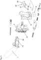
- the Figure 1 shows the steering column switch additionally without a locking curve 7, which is in the Figures 2 and 3
- the following description refers to all figures together.
- the steering column switch has a switching piece 3, on which axle stubs are formed as bearing points 14 on two opposing outer surfaces. In the fully assembled state, the axle stubs are inserted as bearing points 14 in recesses of a housing (not shown here), whereby the switching piece 3 is pivotably mounted about a first axis 4.
- the housing can be arranged in particular on the steering column of a motor vehicle or even designed as a component of the steering column.
- the switching piece 3 has an opening 13, to the side of which there are two bearing points 2 on which the switching lever 1 is pivotably mounted about a second axis 5.
- An end piece 15 of the switching lever 1 extends through the opening 13 of the switching piece 3.
- a device consisting of several components is arranged on the switching piece 3, the function of which is to return the switching lever 1 from a deflected position to a basic position, and which are referred to here collectively as the trigger system 12.
- the functioning of the trigger system 12 will not be described in detail here, since it is basically known and is not essential for understanding the invention.
- the basic functioning of a trigger system is described, for example, in the German utility model DE 81 12 331 U1 explained.
- the end piece 15 is firmly connected to a handle 16 of the shift lever 1, which is provided for the manual operation of the shift lever 1 and through whose movements in different directions, firstly the shift piece 3 can be pivoted about the first axis 4 and secondly the shift lever 1 within the shift piece 3 can be pivoted about the second axis 5.
- the bearing points 2 for the shift lever 1 are thus aligned with the bearing points 14 of the shift piece 3 is arranged such that the first and second axes 4, 5 are aligned perpendicular to each other.
- a locking sleeve 6 loaded with a compression spring 17 is arranged within a bore in the end piece 15, the tip of which rests on the locking curve 7 and can lock there in several positions. These positions, which the gearshift lever 1 can assume either stably or unstably on the locking curve 7, define the possible switching positions of the gearshift lever 1.
- the currently set switching position of the gearshift lever 1 is determined by means of a magnetic sensor.
- the position of a magnet 8 relative to a magnetic sensor 9 is detected by evaluating the signals of the magnetic sensor 9 using electronics not shown here.
- the magnet 8 is firmly connected to a carriage 10 which is mounted on the switching piece 3 so as to be linearly displaceable parallel to the first axis 4 and which follows the movements of the switching lever 1 about the second axis 5 and which is pivoted when the switching piece 3 pivots about the first axis 4.
- the slide 10 is designed like a frame and has a recess 11 through which the locking sleeve 6 and parts of the trigger system 12 are guided. Due to the frame-like structure, the slide 10 is very compact and requires only a small amount of installation space on the switching piece 3.
- the slide 10 has two parallel side parts 20 which are connected to a sliding guide by means of sliding grooves 21 formed on the switching piece 3.
- guide elements formed on the inside of the side parts 20 are inserted into the sliding grooves 21.
- the guide elements which cannot be seen in the figures, can be designed in particular in the form of short pins.
- the side parts 20 are provided with a cross member 22 which is coupled to the end piece 15 of the gearshift lever 1 via a driving element 23.
- the lower part of the carriage 10 is formed by a magnet holder 18 which carries one or more magnets 8.
- the at least one magnet 8 can preferably be glued or injected into the magnet holder 18.
- the magnet holder 18 can either be formed in one piece with the side parts 20 of the carriage 10 or, as shown in the figures, can be manufactured as a single part which is connected to the side parts 20 of the carriage 10, for example by locking.
- Movements of the magnet 8 are detected by a magnetic sensor 9, which is arranged on a circuit board 19, which is fixed relative to the housing (not shown here).
- the magnetic sensor 9, which can preferably be designed as a three-dimensional Hall sensor, detects both the intensity and the direction of the magnetic field penetrating it, and can therefore distinguish between linear movements and pivoting movements of the carriage 10.
- the alignment of the magnet(s) 8 to the magnetic sensor 9 does not have to be in the longitudinal direction of the steering column switch, as shown in the figures, i.e. approximately parallel to the locking sleeve 6. Instead, an arrangement of the magnet holder 18 on the slide 10 rotated about the first axis 4 can also be provided, with the alignment of the magnetic sensor 9 being adjusted accordingly.
- FIGS. 4 to 6 illustrate a particularly advantageous embodiment of the steering column switch according to the invention.
- the structure of this second embodiment corresponds to that of the previously described Figures 1 to 3 described first embodiment in many details; therefore, a repetition of the explanation of the details already described can be dispensed with here.
- the following description therefore relates primarily to the features that distinguish the two versions. Reference symbols already introduced in the first embodiment are retained for identical and equivalent parts.
- the bell crank 24 is particularly clearly visible as a single part in the Figure 5 It consists of a connecting web 28, onto which first and second slotted guides 25, 26 are formed, arranged parallel to one another, as well as a bearing pin 27 arranged between them.
- the bearing pins 27 are inserted into bearing recesses 37 on the switching piece 3, whereby the reversing lever 24 is rotatably mounted on the switching piece 3.
- First guide pins 35 formed on the slide 10 engage in the first elongated hole guides 25, one of which is in the Figure 6
- the second slotted guides 26 of the reversing lever 24 act with second guide pins 36 at the end piece 15 of the shift lever 1.
- the reversing lever 24 thus forms a two-armed lever in the physical sense.
- the pivoting of the shift lever 1 about its second axis 5 causes a pivoting of the reversing lever 24 and at the same time a displacement of the carriage 10 coupled to the reversing lever 24.
- the carriage 10 moves in the opposite direction to the end piece 15 of the shift lever 1 or exactly in accordance with the direction of movement of the handle of the shift lever 1.
- the magnet 8 assumes a unique position in each switching position, which is different enough from all other positions so that it can be reliably detected by the magnetic sensor 9.
Landscapes
- Engineering & Computer Science (AREA)
- Mechanical Engineering (AREA)
- Switches With Compound Operations (AREA)
- Arrangement Or Mounting Of Control Devices For Change-Speed Gearing (AREA)
- Mechanical Control Devices (AREA)
Description
- Die Erfindung betrifft einen Lenkstockschalter für ein Kraftfahrzeug, mit einem in zwei zueinander senkrechten Richtungen verschwenkbaren Schalthebel, mit einem um eine erste Achse verschwenkbar gelagerten Schaltstück, wobei der Schalthebel in dem Schaltstück um eine zur ersten Achse senkrecht angeordnete zweiten Achse verschwenkbar gelagert ist, wobei der Schalthebel an einem Endstück eine federbelastete Rasthülse trägt, die in einer Rastkurve an verschiedenen Positionen einrastbar ist, und mit mindestens einem Magneten und mindestens einem Magnetsensor, die durch Bewegungen des Schalthebels relativ zueinander positionierbar sind.
- Zur Erkennung der eingestellten Position des Schalthebels ist somit ein magnetisches Schaltsystem vorgesehen. Bei einem Lenkstockschalter mit einem solchen Schaltsystem ist üblicherweise ein als Dauermagnet ausgeführter Magnet entweder am Schalthebel angeordnet oder mit dem Schalthebel verbunden, so dass der Magnet direkt den Schwenkbewegungen des Schalthebels folgt.
- Ein derartiger Lenkstockschalter ist aus der deutschen Offenlegungsschrift
DE 10 2011 111 871 A1 bekannt. Die in diesem Dokument beschriebene Vorrichtung sieht einen Betätigungshebel mit einem daran angeordneten Magneten vor, wobei an einer Kulisse, die eine Vielzahl von möglichen Raststellungen für den Betätigungshebel aufweist, an jeder Raststellung ein Magnetsensor angeordnet ist. - Ein solcher Aufbau ist schon allein wegen der Vielzahl von erforderlichen Magnetsensoren relativ aufwendig. Bei diesem Lenkstockschalter sind die Magnetsensoren zudem hinter der Rastkurve angeordnet, was sich ungünstig auf die Baulänge des Lenkstockschalters auswirkt.
- Außer einem Rastsystem zur Erzeugung einer Betätigungshaptik und einem Schaltsystem zur Ermittlung der eingestellten Schaltstellung des Schalthebels, hier ausgeführt durch eine Magnetsensorik, weisen viele Lenkstockschalter noch ein Auslösesystem auf, welches eine automatische Rückstellung des Schalthebels aus den Schaltstellungen ermöglicht, in denen der Lenkstockschalter als Blinkgeberschalter fungiert.
- Einem Lenkstockschalter in einem Kraftfahrzeug steht üblicherweise nur ein begrenzter Bauraum zur Verfügung. Die vorgenannten Systeme müssen daher aufeinander abgestimmt sein, damit sie alle in dem zur Verfügung stehenden Bauraum untergebracht werden können.
- Da sowohl das Auslösesystem, als auch das Rastsystem hinsichtlich ihrer Position und ihrer Anordnung nicht viele Freiheitsgrade besitzen, muss das magnetische Schaltsystem meist einen Platz seitlich neben diesen beiden finden. Die Suche nach einer geeigneten Position ist oft ein Kompromiss zwischen Bauraumbedarf und Systemrobustheit.
- Die Offenlegungsschrift
US 2009/139850A1 zeigt einen Lenkstockschalter gemäß dem Oberbegriff des Patentanspruchs 1. An dem Schaltstück dieses Lenkstockschalters ist ein mit einem Magneten verbundener Schlitten so gelagert, dass dieser senkrecht zu einer ersten Achse linear verschiebbar ist und der den Bewegungen des Schalthebels um eine zweite Achse folgt. Bei Schwenkbewegungen des Schalthebels um dessen erste Achse wird der Magnet mitverschwenkt. - Es stellte sich daher die Aufgabe, einen derartigen Lenkstockschalter mit einem besonders kompakten und die anderen Komponenten möglichst wenig beeinflussenden Schaltsystem zu schaffen.
- Diese Aufgabe wird erfindungsgemäß dadurch gelöst, dass der mindestens eine Magnet fest mit einem Schlitten verbunden ist, der parallel zur ersten Achse linear verschiebbar am Schaltstück gelagert ist und der den Bewegungen des Schalthebels um die zweite Achse folgt, und dass der mindestens eine Magnet bei Schwenkbewegungen des Schaltstücks um dessen erste Achse mit verschwenkt wird.
- Das hier vorgeschlagene Schaltsystem ist somit in einer Richtung linear geführt. Dagegen arbeiten viele bekannte Schaltsysteme sowohl in der horizontalen als auch der vertikalen Schaltrichtung des Schalthebels rotatorisch.
- Das vorgeschlagene Schaltsystem kann aufgrund seines Aufbaus so angeordnet werden, daß es die anderen Systeme wenig bis gar nicht beeinflusst und selbst ebenfalls nicht durch anderen Systeme eingeschränkt wird.
- Diesbezüglich besonders vorteilhaft ist es, wenn der Schlitten rahmenartig ausgebildet ist und eine Ausnehmung aufweist, durch die die Rasthülse hindurchgeführt ist.
- Ebenfalls sehr vorteilhaft kann auch mindestens ein Teil eines Auslösesystems, welches zum Zurückführen des Schalthebels aus einer betätigten Schaltstellung geeignet ist, durch die Ausnehmung hindurchgeführt sein.
- Das magnetische Schaltsystem kann um das Auslösesystem "herumgreifen", und mit seiner Sensorik unterhalb des Rastsystems angeordnet sein. Durch diese Anordnung kann das Schaltsystem weitgehend unbeeinflusst von den andern Systemen hinsichtlich der Robustheit optimiert werden.
- Des Weiteren bringen der Aufbau und die Ansteuerung des erfindungsgemäßen Schaltsystems den Vorteil von zusätzlichen Freiheitsgraden bei der Positionierung des Schaltsystems mit sich: während bekannte Systeme nur eine eingeschränkte Ausrichtung erlauben, ohne sich teils erhebliche Nachteile bei der Auswertung einzukaufen, kann die Sensorik des erfindungsgemäßen Schaltsystems frei um die erste Schwenkachse des Schaltstücks herum gedreht angeordnet werden, ohne daß sich die Qualität der Auswertung verschlechtert.
- Besonders vorteilhaft ist es, vorzusehen, dass der Schlitten mittels eines am Schaltstück drehbar gelagerten Umlenkhebels mit dem Schalthebel gekoppelt ist. Hierdurch wird erreicht, dass der Umlenkhebel Bewegungen des Schalthebels um die zweite Achse mit einer Hebelübersetzung auf den Schlitten überträgt.
- Nachfolgend soll die Erfindung anhand der Zeichnung dargestellt und erläutert werden. Die
Figuren 1 bis 3 zeigen jeweils ein erstes Ausführungsbeispiel eines erfindungsgemäßen Lenkstockschalters ohne ein umgebendes Gehäuse, und zwar in der - Figur 1
- in einer Draufsicht, in der
- Figur 2
- in eine Explosionsansicht, und in der
- Figur 3
- in einer Schnittansicht.
- Die
Figuren 4 bis 6 zeigen jeweils ein zweites Ausführungsbeispiel eines erfindungsgemäßen Lenkstockschalters ohne ein umgebendes Gehäuse, und zwar in der - Figur 4
- in einer Draufsicht, in der
- Figur 5
- in eine Explosionsansicht, und in der
- Figur 6
- in einer Schnittansicht.
- Die
Figur 1 zeigt den Lenkstockschalter zusätzlich ohne eine Rastkurve 7, welche aber in denFiguren 2 und3 dargestellt ist. Die nachfolgende Beschreibung bezieht sich auf alle Figuren gemeinsam. - Der Lenkstockschalter weist ein Schaltstück 3 auf, an dem an zwei einander gegenüberliegenden Außenflächen Achsstummel als Lagerstellen 14 angeformt sind. Im vollständig montierten Zustand sind die Achsstummel als Lagerstellen 14 in Ausnehmungen eines hier nicht dargestellten Gehäuses eingesetzt, wodurch das Schaltstück 3 um eine erste Achse 4 verschwenkbar gelagert ist. Das Gehäuse kann insbesondere an der Lenksäule eines Kraftfahrzeugs angeordnet sein oder sogar als Bestandteil der Lenksäule ausgeführt sein.
- Das Schaltstück 3 weist einen Durchbruch 13 auf, seitlich zu dem sich zwei Lagerstellen 2 befinden, an denen der Schalthebel 1 um eine zweite Achse 5 verschwenkbar gelagert ist. Dabei durchragt ein Endstück 15 des Schalthebels 1 den Durchbruch 13 des Schaltstücks 3.
- Unterhalb des Durchbruchs 13 ist am Schaltstück 3 eine aus mehreren Komponenten bestehende Vorrichtung angeordnet, deren Funktion es ist, den Schalthebel 1 aus einer ausgelenkten Position in eine Grundstellung zurückzuführen, und die hier zusammenfassend als Auslösesystem 12 bezeichnet werden sollen. Die Funktionsweise des Auslösesystems 12 soll hier nicht im Detail beschrieben werden, da grundsätzlich bekannt ist und sie zum Verständnis der Erfindung nicht wesentlich ist. Die prinzipielle Funktionsweise eines Auslösesystem wird beispielsweise in der deutschen Gebrauchsmusterschrift
DE 81 12 331 U1 erläutert. - Das Endstück 15 ist fest mit einem Griffstück 16 des Schalthebels 1 verbunden, das zur manuellen Betätigung des Schalthebels 1 vorgesehen ist und durch dessen Bewegungen in verschiedenen Richtungen erstens das Schaltstück 3 um die erste Achse 4 und zweitens auch der Schalthebel 1 innerhalb des Schaltstücks 3 um die zweite Achse 5 verschwenkt werden kann. Dabei sind die Lagerstellen 2 für den Schalthebel 1 so zu den Lagerstellen 14 des Schaltstücks 3 angeordnet, dass die erste und zweite Achse 4, 5 senkrecht zueinander ausgerichtet sind.
- Innerhalb einer Bohrung im Endstück 15 ist eine mit einer Druckfeder 17 belastete Rasthülse 6 angeordnet, die mit ihrer Spitze an der Rastkurve 7 anliegt und dort an mehreren Positionen einrasten kann. Diese Positionen, die der Schalthebel 1 entweder stabil oder labil an der Rastkurve 7 einnehmen kann, definieren die möglichen Schaltstellungen des Schalthebels 1.
- Die aktuell eingestellte Schaltstellung des Schalthebels 1 wird mittels einer Magnetsensorik ermittelt. Dazu wird die Position eines Magneten 8 relativ zu einem Magnetsensor 9 erfasst, indem die Signale des Magnetsensors 9 durch eine hier nicht darstellte Elektronik ausgewertet werden.
- Erfindungsgemäß ist vorgesehen, dass der Magnet 8 fest mit einem Schlitten 10 verbunden ist, der parallel zur ersten Achse 4 linear verschiebbar am Schaltstück 3 gelagert ist und der den Bewegungen des Schalthebels 1 um die zweite Achse 5 folgt, und der bei Schwenkbewegungen des Schaltstücks 3 um die erste Achse 4 mit verschwenkt wird.
- Der Schlitten 10 ist dazu rahmenartig ausgebildet und weist eine Ausnehmung 11 auf, durch die die Rasthülse 6 sowie Teile des Auslösesystems 12 hindurchgeführt sind. Durch den rahmenartigen Aufbau ist der Schlittens 10 sehr kompakt ausgebildet und benötigt nur wenig Anbauraum am Schaltstück 3.
- Der Schlitten 10 weist zwei zueinander parallele Seitenteile 20 auf, welche mit am Schaltstück 3 angeformten Gleitnuten 21 zu einer Gleitführung verbunden sind. Hierzu sind an den Innenseiten der Seitenteile 20 angeformte Führungselemente in die Gleitnuten 21 eingesetzt. Die in den Figuren nicht erkennbaren Führungselemente können insbesondere in Form kurzer Stifte ausgebildet sein. Im oberen Teil des Schlittens 10 sind die Seitenteile 20 mit einem Querträger 22 verbunden, der über ein Mitnahmeelement 23 mit dem Endstück 15 des Schalthebels 1 gekoppelt ist.
- Der untere Teil des Schlittens 10 wird durch einen Magnethalter 18 gebildet, der einen oder mehrere Magnete 8 trägt. Der mindestens eine Magnet 8 kann vorzugsweise in den Magnethalter 18 eingeklebt oder eingespritzt sein. Der Magnethalter 18 kann entweder einstückig mit den Seitenteilen 20 des Schlittens 10 ausgebildet sein oder, wie in den Figuren dargestellt, als ein Einzelteil gefertigt sein, das mit den Seitenteilen 20 des Schlittens 10, etwa durch Verrasten, verbunden ist.
- Bewegungen des Magneten 8 werden durch einen Magnetsensor 9 erfasst, der auf einer Leiterplatte 19 angeordnet ist, die relativ zu dem hier nicht dargestellten Gehäuse fest angeordnet ist. Der Magnetsensor 9, der bevorzugt als ein dreidimensional messender Hallsensor ausgeführt sein kann, erfasst sowohl die Intensität als auch die Richtung des ihn durchdringenden Magnetfelds, und kann dadurch Linearbewegungen und Schwenkbewegungen des Schlittens 10 unterscheiden.
- Bei der in den Figuren dargestellten Ausführung werden keine beweglichen Anschlussleitungen für den Magnetsensor 9 benötigt.
- Die Ausrichtung des/der Magneten 8 zum Magnetsensor 9 muss keineswegs, wie in den Figuren dargestellt, in Längsrichtung des Lenkstockschalters, also etwa parallel zur Rasthülse 6 sein. Stattdessen kann auch eine um die erste Achse 4 gedrehte Anordnung des Magnethalters 18 am Schlitten 10 vorgesehen werden, wobei die Ausrichtung des Magnetsensors 9 entsprechend angepasst ist.
- Eine solche gedrehte Ausrichtung des Schaltsystems hat keinen Einfluss auf die Auswertung, schafft aber eine erhöhte Flexibilität bei der Ausgestaltung des Lenkstockschalters.
- Die
Figuren 4 bis 6 verdeutlichen eine besonders vorteilhafte Ausführung des erfindungsgemäßen Lenkstockschalters. Der Aufbau dieses zweiten Ausführungsbeispiels stimmt mit dem des zuvor anhand derFiguren 1 bis 3 beschriebenen ersten Ausführungsbeispiels in vielen Details überein; daher kann auf eine Wiederholung der Erläuterung der bereits beschriebenen Details hier verzichtet werden. Die nachfolgende Beschreibung bezieht sich daher vor allem auf die die beiden Ausführungen unterscheidenden Merkmale. Bereits am ersten Ausführungsbeispiel eingeführte Bezugszeichen werden für gleiche und gleichwirkende Teile beibehalten. - Charakteristisch für das in den
Figuren 4 bis 6 dargestellte Ausführungsbeispiel ist, dass hierbei der Schlitten 10 mittels eines am Schaltstück 3 drehbar gelagerten Umlenkhebels 24 mit dem Schalthebel 1 gekoppelt ist, wodurch der Umlenkhebel 24 Bewegungen des Schalthebels 1 um die zweite Achse 5 mit einer Hebelübersetzung auf den Schlitten 10 überträgt. - Der Umlenkhebel 24 ist als Einzelteil besonders deutlich in der
Figur 5 zu erkennen. Er besteht aus einem Verbindungssteg 28, an den einander parallel gegenüberstehend jeweils erste und zweite Langlochführungen 25, 26 sowie ein dazwischen angeordneter Lagerstift 27 angeformt sind. - Die Lagerstifte 27 sind in Lagerausnehmungen 37 am Schaltstück 3 eingesetzt, wodurch der Umlenkhebel 24 am Schaltstück 3 drehbar gelagert ist. In die ersten Langlochführungen 25 greifen am Schlitten 10 angeformte erste Führungsstifte 35 ein, von denen einer in der
Figur 6 erkennbar ist. Die zweiten Langlochführungen 26 des Umlenkhebels 24 wirken mit zweiten Führungsstiften 36 am Endstück 15 des Schalthebels 1 zusammen. Der Umlenkhebel 24 bildet so einen im physikalischen Sinne zweiarmigen Hebel aus. - Das Verschwenken des Schalthebels 1 um seine zweite Achse 5 bewirkt so ein Verschwenken des Umlenkhebels 24 und zugleich ein Verschieben des mit dem Umlenkhebel 24 gekoppelten Schlittens 10. Hierbei bewegt sich der Schlitten 10 umgekehrt zum Endstück 15 des Schalthebels 1 beziehungsweise genau entsprechend der Bewegungsrichtung des Griffstücks des Schalthebels 1.
- Für die Funktionsweise des gesamten Schaltsystems ist es wichtig, daß der Magnet 8 in jeder Schaltstellung eine eindeutige Position einnimmt, die sich von allen anderen Positionen genug unterscheidet, damit diese sicher vom Magnetsensor 9 detektiert werden kann.
- Bei einer Schwenkbewegung des Schalthebels 1 um die zweite Achse 5 ist der erreichbare Hub des Schlittens 10 bei einer direkten Mitnahme durch den Schalthebel 1, wie er in den
Figuren 1 bis 3 dargestellt ist, unmittelbar von der Schaltbewegung des Schalthebels 1 abhängig. Eine Verschwenkung des Schalthebels 1 um einen kleinen Winkel führt somit zu einem geringen Hub des Schlittens 10 und damit auch des Magneten 8. - Ist die Schwenkbewegung des Schalthebels 1 um die zweite Achse 5 zu klein, wird kein ausreichender Hub des Magneten 8 erreicht, um dessen Positionen sicher zu erkennen und von anderen Positionen zu unterscheiden.
- Mithilfe des Umlenkhebels 24, können gemäß des zweiten Ausführungsbeispiels kleine Schwenkbewegungen des Schalthebels 1 entsprechend übersetzt und damit vergrößert werden. Kleine Schwenkbewegungen des Schalthebels 1 können so einen relativ großen Hub des Schlittens 10 und des daran angeordneten Magneten 8 bewirken.
- Damit ist die Linearbewegung des Schlittens 10 nicht mehr allein von der Schwenkbewegung des Schalthebels 1 abhängig, sondern wird auch durch das durch den Umlenkhebel 24 verwirklichte Übersetzungsverhältnis mitbestimmt.
-
- 1
- Schalthebel
- 2
- Lagerstellen
- 3
- Schaltstück
- 4
- erste Achse
- 5
- zweite Achse
- 6
- Rasthülse
- 7
- Rastkurve
- 8
- Magnet
- 9
- Magnetsensor
- 10
- Schlitten
- 11
- Ausnehmung
- 12
- Auslösesystem
- 13
- Durchbruch
- 14
- Lagerstellen
- 15
- Endstück
- 16
- Griffstück
- 17
- Druckfeder
- 18
- Magnethalter
- 19
- Leiterplatte
- 20
- Seitenteile
- 21
- Gleitnuten
- 22
- Querträger
- 23
- Mitnahmeelement
- 24
- Umlenkhebel
- 25
- erste Langlochführungen
- 26
- zweite Langlochführungen
- 27
- Lagerstifte
- 28
- Verbindungssteg
- 35
- erste Führungsstifte
- 36
- zweite Führungsstifte
- 37
- Lagerausnehmungen
Claims (4)
- Lenkstockschalter für ein Kraftfahrzeug,mit einem in zwei zueinander senkrechten Richtungen verschwenkbaren Schalthebel (1),mit einem um eine erste Achse (4) verschwenkbar gelagerten Schaltstück (3),wobei der Schalthebel (1) in dem Schaltstück (3) um eine zur ersten Achse (4) senkrecht angeordnete zweiten Achse (5) verschwenkbar gelagert ist,wobei der Schalthebel (1) an einem Endstück (15) eine federbelastete Rasthülse (6) trägt, die in einer Rastkurve (7) an verschiedenen Positionen einrastbar ist,und mit mindestens einem Magneten (8) und mindestens einem Magnetsensor (9), die durch Bewegungen des Schalthebels (1) relativ zueinander positionierbar sind,dadurch gekennzeichnet,dass der mindestens eine Magnet (8) fest mit einem Schlitten (10) verbunden ist, der parallel zur ersten Achse (4) linear verschiebbar am Schaltstück (3) gelagert ist und der den Bewegungen des Schalthebels (1) um die zweite Achse (5) folgt, unddass der mindestens eine Magnet (8) bei Schwenkbewegungen des Schaltstücks (3) um dessen erste Achse (4) mit verschwenkt wird.
- Lenkstockschalter nach Anspruch 1, dadurch gekennzeichnet, dass der Schlitten (10) rahmenartig ausgebildet ist und eine Ausnehmung (11) aufweist, durch die die Rasthülse (6) hindurchgeführt ist.
- Lenkstockschalter nach Anspruch 2, dadurch gekennzeichnet, dass mindestens ein Teil eines Auslösesystems (12), welches zum Zurückführen des Schalthebels (1) aus einer betätigten Schaltstellung geeignet ist, durch die Ausnehmung (11) hindurchgeführt ist.
- Lenkstockschalter nach Anspruch 1, dadurch gekennzeichnet, dass der Schlitten (10) mittels eines am Schaltstück (3) drehbar gelagerten Umlenkhebels (24) mit dem Schalthebel (1) gekoppelt ist.
Applications Claiming Priority (2)
| Application Number | Priority Date | Filing Date | Title |
|---|---|---|---|
| DE102020007438.3A DE102020007438A1 (de) | 2020-12-07 | 2020-12-07 | Lenkstockschalter für ein Kraftfahrzeug |
| PCT/EP2021/084231 WO2022122592A1 (de) | 2020-12-07 | 2021-12-03 | Lenkstockschalter für ein kraftfahrzeug |
Publications (2)
| Publication Number | Publication Date |
|---|---|
| EP4255774A1 EP4255774A1 (de) | 2023-10-11 |
| EP4255774B1 true EP4255774B1 (de) | 2024-06-12 |
Family
ID=80091347
Family Applications (1)
| Application Number | Title | Priority Date | Filing Date |
|---|---|---|---|
| EP21830418.6A Active EP4255774B1 (de) | 2020-12-07 | 2021-12-03 | Lenkstockschalter für ein kraftfahrzeug |
Country Status (7)
| Country | Link |
|---|---|
| US (1) | US12221031B2 (de) |
| EP (1) | EP4255774B1 (de) |
| KR (1) | KR102926646B1 (de) |
| CN (1) | CN116547169B (de) |
| DE (1) | DE102020007438A1 (de) |
| ES (1) | ES2988397T3 (de) |
| WO (1) | WO2022122592A1 (de) |
Family Cites Families (17)
| Publication number | Priority date | Publication date | Assignee | Title |
|---|---|---|---|---|
| DE8112331U1 (de) | 1981-04-25 | 1981-09-17 | Fa. Leopold Kostal, 5880 Lüdenscheid | Lenkstockschalter |
| US5224393A (en) * | 1990-05-11 | 1993-07-06 | Honda Giken Kogyo Kabushiki Kaisha | Electronically controlled transmission and steering wheel located shift mechanism |
| DE4109544A1 (de) * | 1991-03-22 | 1992-09-24 | Kirsten Elektrotech | Elektrischer schalter |
| FR2784252B1 (fr) | 1998-10-01 | 2000-12-22 | Valeo Electronique | Commutateur sans contact pour ensemble haut de colonne de direction de vehicule automobile |
| DE29901614U1 (de) | 1999-01-30 | 1999-04-15 | Leopold Kostal GmbH & Co KG, 58507 Lüdenscheid | Elektrischer Schalter zum kontaktlosen Schalten |
| JP2001143558A (ja) * | 1999-11-18 | 2001-05-25 | Alps Electric Co Ltd | ストークスイッチ |
| JP3875562B2 (ja) | 2001-06-25 | 2007-01-31 | 矢崎総業株式会社 | コンビネーションスイッチ |
| ATE407032T1 (de) * | 2006-07-07 | 2008-09-15 | Delphi Tech Inc | Lenkstockschalter |
| DE102006057571A1 (de) | 2006-12-06 | 2008-06-12 | Valeo Schalter Und Sensoren Gmbh | Lenkstockschalter für Kraftfahrzeuge |
| JP4830910B2 (ja) * | 2007-03-01 | 2011-12-07 | パナソニック株式会社 | レバースイッチ |
| JP2009134944A (ja) * | 2007-11-29 | 2009-06-18 | Alps Electric Co Ltd | ストークスイッチ装置 |
| DE102011111871A1 (de) | 2011-08-24 | 2013-02-28 | Valeo Schalter Und Sensoren Gmbh | Betätigungsvorrichtung für ein Fahrzeug, welche zur Betätigung einer Funktionseinheit des Fahrzeugs ausgebildet ist, sowie Fahrzeug mit einer derartigen Betätigungsvorrichtung |
| JP2016012465A (ja) * | 2014-06-27 | 2016-01-21 | 株式会社東海理化電機製作所 | レバースイッチ装置 |
| JP6242759B2 (ja) * | 2014-06-30 | 2017-12-06 | 株式会社東海理化電機製作所 | 回転移動検出装置 |
| DE102015000419A1 (de) * | 2015-01-14 | 2016-07-14 | Leopold Kostal Gmbh & Co. Kg | Lenkstockschalter für ein Kraftfahrzeug |
| DE102017111052A1 (de) * | 2017-05-22 | 2018-11-22 | Valeo Schalter Und Sensoren Gmbh | Schalter mit Umlenkhebel und großem Schaltweg |
| CN107452540A (zh) * | 2017-09-01 | 2017-12-08 | 昌辉汽车电器(黄山)股份公司 | 一种汽车用组合开关结构 |
-
2020
- 2020-12-07 DE DE102020007438.3A patent/DE102020007438A1/de active Pending
-
2021
- 2021-12-03 CN CN202180079329.XA patent/CN116547169B/zh active Active
- 2021-12-03 KR KR1020237017138A patent/KR102926646B1/ko active Active
- 2021-12-03 WO PCT/EP2021/084231 patent/WO2022122592A1/de not_active Ceased
- 2021-12-03 EP EP21830418.6A patent/EP4255774B1/de active Active
- 2021-12-03 ES ES21830418T patent/ES2988397T3/es active Active
-
2023
- 2023-04-21 US US18/305,007 patent/US12221031B2/en active Active
Also Published As
| Publication number | Publication date |
|---|---|
| KR102926646B1 (ko) | 2026-02-11 |
| WO2022122592A9 (de) | 2024-03-28 |
| ES2988397T3 (es) | 2024-11-20 |
| KR20230116782A (ko) | 2023-08-04 |
| CN116547169A (zh) | 2023-08-04 |
| DE102020007438A1 (de) | 2022-06-09 |
| US12221031B2 (en) | 2025-02-11 |
| CN116547169B (zh) | 2026-04-03 |
| EP4255774A1 (de) | 2023-10-11 |
| WO2022122592A1 (de) | 2022-06-16 |
| US20230256898A1 (en) | 2023-08-17 |
Similar Documents
| Publication | Publication Date | Title |
|---|---|---|
| DE102009015883B4 (de) | Vorrichtung zur Erfassung der Position eines Fahrstufenwählhebels, Kraftfahrzeug | |
| DE2004249C3 (de) | Getriebeschalthebel-Baugruppe für ein mehrgängiges Fahrzeuggetriebe | |
| EP2029393A1 (de) | Verschlussblendenvorrichtung | |
| DE68908925T2 (de) | Fernbetätigungseinrichtung. | |
| EP3330122A1 (de) | Vorrichtung für ein fahrzeugsitz mit einer dreheinheit und einer verschiebeeinheit | |
| DE2727833C2 (de) | Schiebemechanismus einer Schalteinrichtung für ein Kraftfahrzeuggetriebe | |
| EP2122204B1 (de) | Elektrische schalteinrichtung für ein kraftfahrzeug | |
| DE1575564C3 (de) | Halterung für einen Steuerhebel einer Getriebe-Schalteinrichtung | |
| EP0622718B1 (de) | Bedienungshebeleinrichtung | |
| WO2008098896A1 (de) | Elektrische schalteinrichtung für ein kraftfahrzeug | |
| EP0958962A2 (de) | Hebelschalter | |
| DE69602687T2 (de) | Steuerhebelanordnung mit verbesserter Positionsarretierung | |
| EP4255774B1 (de) | Lenkstockschalter für ein kraftfahrzeug | |
| WO2001073320A1 (de) | Schaltvorrichtung für ein automatikgetriebe eines kraftfahrzeuges | |
| EP2794351B1 (de) | Lenkstockschaltereinrichtung für ein kraftfahrzeug und kraftfahrzeug mit einer lenkstockschaltereinrichtung | |
| EP0230661A1 (de) | Schaltvorrichtung | |
| DE3048371A1 (de) | Zweirichtungsschalter | |
| DE69715683T2 (de) | Linearantriebsvorrichtung | |
| DE2750275A1 (de) | Getriebeschaltung mit schwingen | |
| DE10030275B4 (de) | Rastmechanismus für einen Fahrtrichtungsschalter eines Kraftfahrzeugs | |
| DE4416864C1 (de) | Vorrichtung mit einem Wählhebel für Kraftfahrzeug-Automatikgetriebe | |
| EP1245872B1 (de) | Schaltvorrichtung für ein Zahnräderwechselgetriebe, insbesondere für Kraftfahrzeuge | |
| EP3941787B1 (de) | Lenkstockschalter für ein fahrzeug | |
| EP3441262A1 (de) | Lenksäulenmodul für ein kraftfahrzeug mit einer flügelartigen zahnstange an einem lenkstockhebel, sowie kraftfahrzeug mit einem derartigen lenksäulenmodul | |
| EP3557111B1 (de) | Positioniereinrichtung für alignments schwerer anlagenkomponenten |
Legal Events
| Date | Code | Title | Description |
|---|---|---|---|
| STAA | Information on the status of an ep patent application or granted ep patent |
Free format text: STATUS: UNKNOWN |
|
| STAA | Information on the status of an ep patent application or granted ep patent |
Free format text: STATUS: THE INTERNATIONAL PUBLICATION HAS BEEN MADE |
|
| PUAI | Public reference made under article 153(3) epc to a published international application that has entered the european phase |
Free format text: ORIGINAL CODE: 0009012 |
|
| STAA | Information on the status of an ep patent application or granted ep patent |
Free format text: STATUS: REQUEST FOR EXAMINATION WAS MADE |
|
| 17P | Request for examination filed |
Effective date: 20230621 |
|
| AK | Designated contracting states |
Kind code of ref document: A1 Designated state(s): AL AT BE BG CH CY CZ DE DK EE ES FI FR GB GR HR HU IE IS IT LI LT LU LV MC MK MT NL NO PL PT RO RS SE SI SK SM TR |
|
| DAV | Request for validation of the european patent (deleted) | ||
| DAX | Request for extension of the european patent (deleted) | ||
| GRAP | Despatch of communication of intention to grant a patent |
Free format text: ORIGINAL CODE: EPIDOSNIGR1 |
|
| STAA | Information on the status of an ep patent application or granted ep patent |
Free format text: STATUS: GRANT OF PATENT IS INTENDED |
|
| GRAS | Grant fee paid |
Free format text: ORIGINAL CODE: EPIDOSNIGR3 |
|
| GRAA | (expected) grant |
Free format text: ORIGINAL CODE: 0009210 |
|
| STAA | Information on the status of an ep patent application or granted ep patent |
Free format text: STATUS: THE PATENT HAS BEEN GRANTED |
|
| INTG | Intention to grant announced |
Effective date: 20240418 |
|
| INTG | Intention to grant announced |
Effective date: 20240425 |
|
| AK | Designated contracting states |
Kind code of ref document: B1 Designated state(s): AL AT BE BG CH CY CZ DE DK EE ES FI FR GB GR HR HU IE IS IT LI LT LU LV MC MK MT NL NO PL PT RO RS SE SI SK SM TR |
|
| REG | Reference to a national code |
Ref country code: GB Ref legal event code: FG4D Free format text: NOT ENGLISH |
|
| REG | Reference to a national code |
Ref country code: CH Ref legal event code: EP |
|
| REG | Reference to a national code |
Ref country code: IE Ref legal event code: FG4D Free format text: LANGUAGE OF EP DOCUMENT: GERMAN |
|
| REG | Reference to a national code |
Ref country code: DE Ref legal event code: R096 Ref document number: 502021004024 Country of ref document: DE |
|
| REG | Reference to a national code |
Ref country code: SE Ref legal event code: TRGR |
|
| PG25 | Lapsed in a contracting state [announced via postgrant information from national office to epo] |
Ref country code: BG Free format text: LAPSE BECAUSE OF FAILURE TO SUBMIT A TRANSLATION OF THE DESCRIPTION OR TO PAY THE FEE WITHIN THE PRESCRIBED TIME-LIMIT Effective date: 20240612 |
|
| PG25 | Lapsed in a contracting state [announced via postgrant information from national office to epo] |
Ref country code: HR Free format text: LAPSE BECAUSE OF FAILURE TO SUBMIT A TRANSLATION OF THE DESCRIPTION OR TO PAY THE FEE WITHIN THE PRESCRIBED TIME-LIMIT Effective date: 20240612 Ref country code: FI Free format text: LAPSE BECAUSE OF FAILURE TO SUBMIT A TRANSLATION OF THE DESCRIPTION OR TO PAY THE FEE WITHIN THE PRESCRIBED TIME-LIMIT Effective date: 20240612 |
|
| REG | Reference to a national code |
Ref country code: LT Ref legal event code: MG9D |
|
| PG25 | Lapsed in a contracting state [announced via postgrant information from national office to epo] |
Ref country code: GR Free format text: LAPSE BECAUSE OF FAILURE TO SUBMIT A TRANSLATION OF THE DESCRIPTION OR TO PAY THE FEE WITHIN THE PRESCRIBED TIME-LIMIT Effective date: 20240913 |
|
| REG | Reference to a national code |
Ref country code: NL Ref legal event code: MP Effective date: 20240612 |
|
| PG25 | Lapsed in a contracting state [announced via postgrant information from national office to epo] |
Ref country code: LV Free format text: LAPSE BECAUSE OF FAILURE TO SUBMIT A TRANSLATION OF THE DESCRIPTION OR TO PAY THE FEE WITHIN THE PRESCRIBED TIME-LIMIT Effective date: 20240612 |
|
| PG25 | Lapsed in a contracting state [announced via postgrant information from national office to epo] |
Ref country code: NO Free format text: LAPSE BECAUSE OF FAILURE TO SUBMIT A TRANSLATION OF THE DESCRIPTION OR TO PAY THE FEE WITHIN THE PRESCRIBED TIME-LIMIT Effective date: 20240912 Ref country code: LV Free format text: LAPSE BECAUSE OF FAILURE TO SUBMIT A TRANSLATION OF THE DESCRIPTION OR TO PAY THE FEE WITHIN THE PRESCRIBED TIME-LIMIT Effective date: 20240612 Ref country code: HR Free format text: LAPSE BECAUSE OF FAILURE TO SUBMIT A TRANSLATION OF THE DESCRIPTION OR TO PAY THE FEE WITHIN THE PRESCRIBED TIME-LIMIT Effective date: 20240612 Ref country code: GR Free format text: LAPSE BECAUSE OF FAILURE TO SUBMIT A TRANSLATION OF THE DESCRIPTION OR TO PAY THE FEE WITHIN THE PRESCRIBED TIME-LIMIT Effective date: 20240913 Ref country code: FI Free format text: LAPSE BECAUSE OF FAILURE TO SUBMIT A TRANSLATION OF THE DESCRIPTION OR TO PAY THE FEE WITHIN THE PRESCRIBED TIME-LIMIT Effective date: 20240612 Ref country code: BG Free format text: LAPSE BECAUSE OF FAILURE TO SUBMIT A TRANSLATION OF THE DESCRIPTION OR TO PAY THE FEE WITHIN THE PRESCRIBED TIME-LIMIT Effective date: 20240612 Ref country code: RS Free format text: LAPSE BECAUSE OF FAILURE TO SUBMIT A TRANSLATION OF THE DESCRIPTION OR TO PAY THE FEE WITHIN THE PRESCRIBED TIME-LIMIT Effective date: 20240912 |
|
| PG25 | Lapsed in a contracting state [announced via postgrant information from national office to epo] |
Ref country code: NL Free format text: LAPSE BECAUSE OF FAILURE TO SUBMIT A TRANSLATION OF THE DESCRIPTION OR TO PAY THE FEE WITHIN THE PRESCRIBED TIME-LIMIT Effective date: 20240612 |
|
| REG | Reference to a national code |
Ref country code: ES Ref legal event code: FG2A Ref document number: 2988397 Country of ref document: ES Kind code of ref document: T3 Effective date: 20241120 |
|
| PG25 | Lapsed in a contracting state [announced via postgrant information from national office to epo] |
Ref country code: NL Free format text: LAPSE BECAUSE OF FAILURE TO SUBMIT A TRANSLATION OF THE DESCRIPTION OR TO PAY THE FEE WITHIN THE PRESCRIBED TIME-LIMIT Effective date: 20240612 |
|
| PG25 | Lapsed in a contracting state [announced via postgrant information from national office to epo] |
Ref country code: PT Free format text: LAPSE BECAUSE OF FAILURE TO SUBMIT A TRANSLATION OF THE DESCRIPTION OR TO PAY THE FEE WITHIN THE PRESCRIBED TIME-LIMIT Effective date: 20241014 |
|
| PG25 | Lapsed in a contracting state [announced via postgrant information from national office to epo] |
Ref country code: PT Free format text: LAPSE BECAUSE OF FAILURE TO SUBMIT A TRANSLATION OF THE DESCRIPTION OR TO PAY THE FEE WITHIN THE PRESCRIBED TIME-LIMIT Effective date: 20241014 |
|
| PG25 | Lapsed in a contracting state [announced via postgrant information from national office to epo] |
Ref country code: PL Free format text: LAPSE BECAUSE OF FAILURE TO SUBMIT A TRANSLATION OF THE DESCRIPTION OR TO PAY THE FEE WITHIN THE PRESCRIBED TIME-LIMIT Effective date: 20240612 |
|
| PG25 | Lapsed in a contracting state [announced via postgrant information from national office to epo] |
Ref country code: EE Free format text: LAPSE BECAUSE OF FAILURE TO SUBMIT A TRANSLATION OF THE DESCRIPTION OR TO PAY THE FEE WITHIN THE PRESCRIBED TIME-LIMIT Effective date: 20240612 |
|
| PG25 | Lapsed in a contracting state [announced via postgrant information from national office to epo] |
Ref country code: IS Free format text: LAPSE BECAUSE OF FAILURE TO SUBMIT A TRANSLATION OF THE DESCRIPTION OR TO PAY THE FEE WITHIN THE PRESCRIBED TIME-LIMIT Effective date: 20241012 |
|
| PG25 | Lapsed in a contracting state [announced via postgrant information from national office to epo] |
Ref country code: SK Free format text: LAPSE BECAUSE OF FAILURE TO SUBMIT A TRANSLATION OF THE DESCRIPTION OR TO PAY THE FEE WITHIN THE PRESCRIBED TIME-LIMIT Effective date: 20240612 Ref country code: RO Free format text: LAPSE BECAUSE OF FAILURE TO SUBMIT A TRANSLATION OF THE DESCRIPTION OR TO PAY THE FEE WITHIN THE PRESCRIBED TIME-LIMIT Effective date: 20240612 |
|
| PG25 | Lapsed in a contracting state [announced via postgrant information from national office to epo] |
Ref country code: SM Free format text: LAPSE BECAUSE OF FAILURE TO SUBMIT A TRANSLATION OF THE DESCRIPTION OR TO PAY THE FEE WITHIN THE PRESCRIBED TIME-LIMIT Effective date: 20240612 |
|
| PG25 | Lapsed in a contracting state [announced via postgrant information from national office to epo] |
Ref country code: SM Free format text: LAPSE BECAUSE OF FAILURE TO SUBMIT A TRANSLATION OF THE DESCRIPTION OR TO PAY THE FEE WITHIN THE PRESCRIBED TIME-LIMIT Effective date: 20240612 Ref country code: SK Free format text: LAPSE BECAUSE OF FAILURE TO SUBMIT A TRANSLATION OF THE DESCRIPTION OR TO PAY THE FEE WITHIN THE PRESCRIBED TIME-LIMIT Effective date: 20240612 Ref country code: RO Free format text: LAPSE BECAUSE OF FAILURE TO SUBMIT A TRANSLATION OF THE DESCRIPTION OR TO PAY THE FEE WITHIN THE PRESCRIBED TIME-LIMIT Effective date: 20240612 Ref country code: PL Free format text: LAPSE BECAUSE OF FAILURE TO SUBMIT A TRANSLATION OF THE DESCRIPTION OR TO PAY THE FEE WITHIN THE PRESCRIBED TIME-LIMIT Effective date: 20240612 Ref country code: IS Free format text: LAPSE BECAUSE OF FAILURE TO SUBMIT A TRANSLATION OF THE DESCRIPTION OR TO PAY THE FEE WITHIN THE PRESCRIBED TIME-LIMIT Effective date: 20241012 Ref country code: EE Free format text: LAPSE BECAUSE OF FAILURE TO SUBMIT A TRANSLATION OF THE DESCRIPTION OR TO PAY THE FEE WITHIN THE PRESCRIBED TIME-LIMIT Effective date: 20240612 |
|
| REG | Reference to a national code |
Ref country code: DE Ref legal event code: R097 Ref document number: 502021004024 Country of ref document: DE |
|
| PG25 | Lapsed in a contracting state [announced via postgrant information from national office to epo] |
Ref country code: DK Free format text: LAPSE BECAUSE OF FAILURE TO SUBMIT A TRANSLATION OF THE DESCRIPTION OR TO PAY THE FEE WITHIN THE PRESCRIBED TIME-LIMIT Effective date: 20240612 |
|
| PLBE | No opposition filed within time limit |
Free format text: ORIGINAL CODE: 0009261 |
|
| STAA | Information on the status of an ep patent application or granted ep patent |
Free format text: STATUS: NO OPPOSITION FILED WITHIN TIME LIMIT |
|
| 26N | No opposition filed |
Effective date: 20250313 |
|
| PG25 | Lapsed in a contracting state [announced via postgrant information from national office to epo] |
Ref country code: MC Free format text: LAPSE BECAUSE OF FAILURE TO SUBMIT A TRANSLATION OF THE DESCRIPTION OR TO PAY THE FEE WITHIN THE PRESCRIBED TIME-LIMIT Effective date: 20240612 |
|
| REG | Reference to a national code |
Ref country code: CH Ref legal event code: PL |
|
| PG25 | Lapsed in a contracting state [announced via postgrant information from national office to epo] |
Ref country code: LU Free format text: LAPSE BECAUSE OF NON-PAYMENT OF DUE FEES Effective date: 20241203 |
|
| REG | Reference to a national code |
Ref country code: BE Ref legal event code: MM Effective date: 20241231 |
|
| PG25 | Lapsed in a contracting state [announced via postgrant information from national office to epo] |
Ref country code: BE Free format text: LAPSE BECAUSE OF NON-PAYMENT OF DUE FEES Effective date: 20241231 |
|
| PG25 | Lapsed in a contracting state [announced via postgrant information from national office to epo] |
Ref country code: CH Free format text: LAPSE BECAUSE OF NON-PAYMENT OF DUE FEES Effective date: 20241231 |
|
| PG25 | Lapsed in a contracting state [announced via postgrant information from national office to epo] |
Ref country code: IE Free format text: LAPSE BECAUSE OF NON-PAYMENT OF DUE FEES Effective date: 20241203 |
|
| PGFP | Annual fee paid to national office [announced via postgrant information from national office to epo] |
Ref country code: DE Payment date: 20251217 Year of fee payment: 5 |
|
| PGFP | Annual fee paid to national office [announced via postgrant information from national office to epo] |
Ref country code: GB Payment date: 20251218 Year of fee payment: 5 |
|
| PGFP | Annual fee paid to national office [announced via postgrant information from national office to epo] |
Ref country code: AT Payment date: 20260113 Year of fee payment: 5 |
|
| PGFP | Annual fee paid to national office [announced via postgrant information from national office to epo] |
Ref country code: IT Payment date: 20251205 Year of fee payment: 5 |
|
| PGFP | Annual fee paid to national office [announced via postgrant information from national office to epo] |
Ref country code: FR Payment date: 20251230 Year of fee payment: 5 |
|
| PGFP | Annual fee paid to national office [announced via postgrant information from national office to epo] |
Ref country code: SE Payment date: 20251210 Year of fee payment: 5 |
|
| PGFP | Annual fee paid to national office [announced via postgrant information from national office to epo] |
Ref country code: CZ Payment date: 20251121 Year of fee payment: 5 |
|
| PG25 | Lapsed in a contracting state [announced via postgrant information from national office to epo] |
Ref country code: CY Free format text: LAPSE BECAUSE OF FAILURE TO SUBMIT A TRANSLATION OF THE DESCRIPTION OR TO PAY THE FEE WITHIN THE PRESCRIBED TIME-LIMIT; INVALID AB INITIO Effective date: 20211203 |
|
| PGFP | Annual fee paid to national office [announced via postgrant information from national office to epo] |
Ref country code: ES Payment date: 20260122 Year of fee payment: 5 |