EP4256159B1 - Schiebetürbeschlag und verfahren zur montage eines schiebetürbeschlages - Google Patents
Schiebetürbeschlag und verfahren zur montage eines schiebetürbeschlages Download PDFInfo
- Publication number
- EP4256159B1 EP4256159B1 EP21835592.3A EP21835592A EP4256159B1 EP 4256159 B1 EP4256159 B1 EP 4256159B1 EP 21835592 A EP21835592 A EP 21835592A EP 4256159 B1 EP4256159 B1 EP 4256159B1
- Authority
- EP
- European Patent Office
- Prior art keywords
- profiles
- sliding door
- support part
- door fitting
- tensioning
- Prior art date
- Legal status (The legal status is an assumption and is not a legal conclusion. Google has not performed a legal analysis and makes no representation as to the accuracy of the status listed.)
- Active
Links
Images







Classifications
-
- E—FIXED CONSTRUCTIONS
- E05—LOCKS; KEYS; WINDOW OR DOOR FITTINGS; SAFES
- E05D—HINGES OR SUSPENSION DEVICES FOR DOORS, WINDOWS OR WINGS
- E05D15/00—Suspension arrangements for wings
- E05D15/06—Suspension arrangements for wings for wings sliding horizontally more or less in their own plane
- E05D15/0621—Details, e.g. suspension or supporting guides
- E05D15/0626—Details, e.g. suspension or supporting guides for wings suspended at the top
- E05D15/0652—Tracks
-
- E—FIXED CONSTRUCTIONS
- E05—LOCKS; KEYS; WINDOW OR DOOR FITTINGS; SAFES
- E05Y—INDEXING SCHEME ASSOCIATED WITH SUBCLASSES E05D AND E05F, RELATING TO CONSTRUCTION ELEMENTS, ELECTRIC CONTROL, POWER SUPPLY, POWER SIGNAL OR TRANSMISSION, USER INTERFACES, MOUNTING OR COUPLING, DETAILS, ACCESSORIES, AUXILIARY OPERATIONS NOT OTHERWISE PROVIDED FOR, APPLICATION THEREOF
- E05Y2201/00—Constructional elements; Accessories therefor
- E05Y2201/60—Suspension or transmission members; Accessories therefor
- E05Y2201/622—Suspension or transmission members elements
- E05Y2201/684—Rails; Tracks
-
- E—FIXED CONSTRUCTIONS
- E05—LOCKS; KEYS; WINDOW OR DOOR FITTINGS; SAFES
- E05Y—INDEXING SCHEME ASSOCIATED WITH SUBCLASSES E05D AND E05F, RELATING TO CONSTRUCTION ELEMENTS, ELECTRIC CONTROL, POWER SUPPLY, POWER SIGNAL OR TRANSMISSION, USER INTERFACES, MOUNTING OR COUPLING, DETAILS, ACCESSORIES, AUXILIARY OPERATIONS NOT OTHERWISE PROVIDED FOR, APPLICATION THEREOF
- E05Y2600/00—Mounting or coupling arrangements for elements provided for in this subclass
- E05Y2600/50—Mounting methods; Positioning
- E05Y2600/52—Toolless
-
- E—FIXED CONSTRUCTIONS
- E05—LOCKS; KEYS; WINDOW OR DOOR FITTINGS; SAFES
- E05Y—INDEXING SCHEME ASSOCIATED WITH SUBCLASSES E05D AND E05F, RELATING TO CONSTRUCTION ELEMENTS, ELECTRIC CONTROL, POWER SUPPLY, POWER SIGNAL OR TRANSMISSION, USER INTERFACES, MOUNTING OR COUPLING, DETAILS, ACCESSORIES, AUXILIARY OPERATIONS NOT OTHERWISE PROVIDED FOR, APPLICATION THEREOF
- E05Y2600/00—Mounting or coupling arrangements for elements provided for in this subclass
- E05Y2600/60—Mounting or coupling members; Accessories therefor
- E05Y2600/626—Plates or brackets
-
- E—FIXED CONSTRUCTIONS
- E05—LOCKS; KEYS; WINDOW OR DOOR FITTINGS; SAFES
- E05Y—INDEXING SCHEME ASSOCIATED WITH SUBCLASSES E05D AND E05F, RELATING TO CONSTRUCTION ELEMENTS, ELECTRIC CONTROL, POWER SUPPLY, POWER SIGNAL OR TRANSMISSION, USER INTERFACES, MOUNTING OR COUPLING, DETAILS, ACCESSORIES, AUXILIARY OPERATIONS NOT OTHERWISE PROVIDED FOR, APPLICATION THEREOF
- E05Y2600/00—Mounting or coupling arrangements for elements provided for in this subclass
- E05Y2600/60—Mounting or coupling members; Accessories therefor
- E05Y2600/628—Profiles; Strips
-
- E—FIXED CONSTRUCTIONS
- E05—LOCKS; KEYS; WINDOW OR DOOR FITTINGS; SAFES
- E05Y—INDEXING SCHEME ASSOCIATED WITH SUBCLASSES E05D AND E05F, RELATING TO CONSTRUCTION ELEMENTS, ELECTRIC CONTROL, POWER SUPPLY, POWER SIGNAL OR TRANSMISSION, USER INTERFACES, MOUNTING OR COUPLING, DETAILS, ACCESSORIES, AUXILIARY OPERATIONS NOT OTHERWISE PROVIDED FOR, APPLICATION THEREOF
- E05Y2900/00—Application of doors, windows, wings or fittings thereof
- E05Y2900/20—Application of doors, windows, wings or fittings thereof for furniture, e.g. cabinets
-
- F—MECHANICAL ENGINEERING; LIGHTING; HEATING; WEAPONS; BLASTING
- F16—ENGINEERING ELEMENTS AND UNITS; GENERAL MEASURES FOR PRODUCING AND MAINTAINING EFFECTIVE FUNCTIONING OF MACHINES OR INSTALLATIONS; THERMAL INSULATION IN GENERAL
- F16B—DEVICES FOR FASTENING OR SECURING CONSTRUCTIONAL ELEMENTS OR MACHINE PARTS TOGETHER, e.g. NAILS, BOLTS, CIRCLIPS, CLAMPS, CLIPS OR WEDGES; JOINTS OR JOINTING
- F16B7/00—Connections of rods or tubes, e.g. of non-circular section, mutually, including resilient connections
- F16B7/04—Clamping or clipping connections
- F16B7/0406—Clamping or clipping connections for rods or tubes being coaxial
- F16B7/0426—Clamping or clipping connections for rods or tubes being coaxial for rods or for tubes without using the innerside thereof
Definitions
- the present invention relates to a sliding door fitting with two profiles connected to one another at a joint via a profile connection, which form at least one track for rollers or sliding bodies of a movable running part, wherein the profile connection has a support part fixed to the profiles and a tensioning element which can be moved relative to the support part via a tensioning mechanism and which pretensions the two profiles towards the support part, and a method for assembling a sliding door fitting, in which a first profile is fixed to a furniture body and a second profile is fixed to the furniture body in an extension of the first profile, wherein a profile connection is fixed at a joint of the first and second profiles.
- the EN 10 2019 101 334 A1 discloses a sliding door fitting for furniture, in which a guide element for a roller is mounted on a guide rail, which forms a guide track next to the track, which causes the roller to be raised and then lowered when it passes over it. This compensates for a slight step formation in the joint area of the two guide rail profiles, as the roller is guided over the guide track of the guide element.
- the installation of the guide element is complex, and the openings in the guide profiles also cause a certain weakening of the material.
- EP 0 572 936 A1 discloses a rail with two adjacent profile pieces of the same cross-section, which are connected by means of a coupling piece. A contact strip of the coupling piece presses against each of the profile pieces in order to clamp them together.
- US 3 431 585 A discloses a rail construction with several rail sections that are supported by connecting elements.
- the connecting elements can be tightened using screws.
- a similar construction is also disclosed by US$2,649,612 and US$1,945,332 .
- the sliding door fitting according to the invention comprises a profile connection at the joint of the interconnected profiles, which has a support part fixed to the profiles and a tensioning element that can be moved relative to the support part via a tensioning mechanism and that pre-tensions the two profiles towards the support part.
- the tensioning element can be moved relative to the support part via the tensioning mechanism in order to align and level the two profiles in the area of the joint, i.e. to compensate for any step between the two profiles.
- the tensioning mechanism can transmit relatively high forces that ensure stabilization at the joint.
- the clamping element can be moved in the vertical direction relative to the support part via the clamping mechanism in the installed position.
- the clamping mechanism can ensure a movement of the clamping element relative to the support part of between 0.5 mm and 4 mm, so that effective clamping is possible.
- the clamping element rests on the two profiles on the side opposite the at least one track.
- the clamping element is positioned on the underside of the lower track and supports it in the clamped position.
- the clamping element can have a protruding bar that grips underneath the track.
- the bar can be arranged continuously over the joint and have a length of, for example, more than 20 mm, so that the entire area adjacent to the joint is supported by the bar.
- the profiles according to the invention have at least two tracks lying one above the other in the installation position, with the clamping element resting on the underside of the lower track.
- the space requirement is minimized by the tracks lying one above the other in the vertical direction, in particular tracks lying essentially in the same plane, and in addition the lower track, which can bend more easily, can be stabilized by the clamping element.
- the support element can have two hooks, with one hook reaching through an opening on one of the two profiles. This allows the support element to engage in a profile with one hook each and be supported there in order to position the clamping element in the desired position.
- the openings on the profiles can be arranged in a vertical section of the profiles so that clamping forces can be effectively transmitted in the vertical direction.
- the clamping mechanism preferably comprises a pivotable clamping lever that is movable relative to the support part.
- a curved guide that is movable along a counter bearing can be formed on the clamping lever or a component connected to the clamping lever.
- the axis of rotation of the clamping lever can be parallel or perpendicular in the longitudinal direction of the profiles.
- a clamping mechanism with a pivotable clamping lever enables tool-free assembly in the manner of a quick release, in which the clamping mechanism with the clamping lever can be mounted as a pre-assembled unit on the two profiles.
- a toggle lever mechanism or another actuating mechanism can also be used for the pivotable clamping lever.
- the clamping mechanism can comprise a threaded rod and a nut screwed onto the threaded rod.
- the nut can also be operated manually via wings or projections, for example as a knurled nut, to enable tool-free assembly of the clamping mechanism.
- the clamping forces between the clamping element and the support part can be effectively adjusted using the nut.
- the profile connection can additionally have a holding element that enables attachment to an underside of the top floor.
- an insert is inserted at or on a track at a joint between the profiles. This allows a weight load to be shifted optionally from the track on the two profiles to the insert at least for a certain travel range in order to achieve improved load distribution in the joint area.
- the sliding door fitting according to the invention is preferably used on a furniture body, in particular on a top panel, in order to store one or more sliding doors in a suspended and movable manner.
- a furniture body in particular on a top panel
- a first profile is first attached to a furniture body and a second profile is attached to the furniture body as an extension of the first profile.
- a profile connection can then be fixed to a joint between the first and second profiles, the profile connection having a support part attached to the profiles and a clamping element that can be moved relative to the support part via a clamping mechanism and that is clamped relative to the support part when fixed to the profiles.
- the movement of the clamping element relative to the support part can be between 0.5 mm and 4 mm, for example, during clamping in order to clamp and stabilize the profiles in the area of the joint.
- the clamping element is tightened relative to the support part without tools via a pivoting lever or a rotatable nut, so that the sliding door fitting can be attached to the furniture body in a short time.
- a cabinet 1 comprises a furniture body 2, which has openings on a front side that can be opened and closed by several sliding doors 5 and 6. Each sliding door 5 and 6 can be moved along a guide rail 3 via running parts 4, which is fixed to an upper floor of the furniture body 2.
- a guide rail 7 is provided on an underside of the furniture body 2, which guides the sliding doors 5 and 6 in the floor area.
- the sliding doors 5 and 6 are arranged in two different levels that are parallel to each other.
- the profile connection 10 comprises a support part 11 which is fixed to the profiles 3a and 3b.
- the support part 11 comprises two hooks 12, each of which passes through an opening in one of the profiles 3a or 3b.
- the profiles 3a and 3b form an upper track 32 and a lower track 33, which are arranged vertically one above the other and horizontally, but essentially in the same plane. It is also possible for the profiles 3a and 3b to have more than two tracks 32 and 33, wherein the tracks can be arranged offset in the vertical or horizontal direction.
- the profile connection 10 comprises a clamping element 13 which is movable in the vertical direction relative to the support part 11.
- the clamping element 13 comprises a strip 14 on a lower side which engages under the lower track 33 on a lower side and can be placed there for support.
- the profile connection 10 comprises a clamping mechanism with a pivotable clamping lever 15, which is rotatably mounted about an axis 16.
- the clamping lever 15 comprises a curved guide 17, spaced radially from the axis 16, the surface of which extends in a different distances from the axis 16.
- the clamping lever 15 is rotatably mounted on the clamping element 13.
- the support part 11 comprises a counter bearing 18 at a lower end, on which the curve guide 17 can be supported when the clamping lever 15 is rotated.
- an edge 20 and a linear section 22 of the clamping lever 15 are arranged adjacent to a stop 21.
- the edge 20 serves to guide an opening movement during a disassembly process.
- the edge 20 runs along the stop 21 and is used to release the support part 11 and the clamping element 13 again and to move them against the clamping direction.
- the linear section 22 adjoining the edge 20, together with the stop 21, limits the opening movement of the clamping lever 15.
- the two profiles 3a and 3b are fixed to the furniture body 2 on the top panel using a fastener, for example a screw 8.
- a fastener for example a screw 8.
- the profile connection 10 is now mounted underneath the top panel, whereby the hooks 12 are first inserted into the openings on the profiles 3a and 3b.
- the clamping lever 15 is then pivoted, in particular in a pivoting range between 60° and 180°, whereby the curve guide 17 is moved along the counter bearing 18 and thus the clamping element 13 with the bar 14 is moved upwards in a vertical direction until the Figures 3A to 3C shown position is reached.
- the counter bearing 18 has reached a step of the curved guide 17, which prevents further rotation of the clamping lever 15 and thus defines an end position of the clamping mechanism.
- the clamping lever 15 has been rotated by approximately 90° and is now aligned parallel to the longitudinal direction of the profiles 3a and 3b.
- lateral guide webs 19 on the clamping element 13 which are bent in an angular or U-shaped manner, ensure vertical guidance of the clamping element 13 relative to the support part 11, which is held with an edge along the guide webs 19.
- the strip 14 engages with an edge under the track 33 and thus supports the joint between the two profiles 3a and 3b.
- the tracks 32 and 33 are convexly curved upwards, so that the edge of the strip 14 engages in the concave receptacle on the underside of the track 33 and is clamped there when the clamping lever 15 is turned.
- the path of the clamping element 13 relative to the support part 11 can be in a range between 0.5 mm and 4 mm.
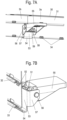
- the profile connection 10 with the profile 3a is shown in an exploded view.
- the profile 3a which is a mirror image of the profile 3b, comprises openings 34 on a vertical section 31, which are arranged adjacent to the track 32 or 33.
- the openings 34 are used for mounting a web-shaped insert 40, which comprises protruding projections 41, which can be inserted into the openings 34 during assembly.
- the inserts 40 are inserted on or next to the track 32 or 33 in order to be able to better distribute the load when the rollers or sliding bodies drive over the joint and to avoid directly driving over the joint.
- FIG 4B the assembled position of the guide rail 3 is shown.
- the two profiles 3a and 3b are arranged in alignment, and at the joint the inserts 40 are arranged adjacent to the tracks 32 or 33.
- FIG. 5 a second embodiment of a sliding door fitting is shown, in which the profiles 3a and 3b are designed as in the first embodiment.
- a modified profile connection 50 is used at the joint of the profiles 3a and 3b.
- the profile connection 50 comprises a support part 51 which has two hooks 52 which, as in the previous embodiment, can be inserted into openings on a vertical section 31 of the profiles 3a and 3b.
- a clamping element 53 is movably held on the support part 51, on the underside of which a strip 54 is formed which engages under the track 33.
- Two bent tabs 57 are provided on the clamping element 53, on which an axis 56 is formed for the rotatable attachment of a clamping lever 55.
- the profile connection 50 is shown in a clamped position in which the clamping lever 55 has been pivoted upwards.
- the clamping lever 55 now protrudes essentially vertically in the horizontal direction from the profiles 3a and 3b.
- a curved guide 59 is formed on the underside of the clamping lever 55 and is supported on a counter bearing 58 of the support part 51. If the clamping lever 55 is pivoted upwards by approximately 90°, the curved guide 59 slides along the counter bearing 58 and moves the axis 56 and thus the clamping element 53 upwards in a vertical direction so that the bar 54 presses against the underside of the track 33. The bar 54 therefore ensures that the webs of the track 33 are precisely aligned.
- the axis 56 of the clamping lever 55 is aligned parallel to the longitudinal direction of the profiles 3a and 3b.
- FIG 8 a third embodiment of a modified profile connection 60 for profiles 3a and 3b is shown.
- the profiles 3a and 3b are designed as in the first embodiments and can optionally have inserts 40 in the area of the joint, which are inserted into openings 34 with projections 41 in order to optimize the distribution of forces when driving over the joint.
- the profile connection 60 comprises a support part 61 which, as in the previous embodiments, has two hooks 62, each of which can be inserted into an opening on one of the profiles 3a or 3b in order to fix the support part 61 there.
- a clamping element 63 is held on the support part 61 so that it can move in the vertical direction and has a strip 64 that engages under a track 33.
- the profile connection 60 does not comprise a pivotable clamping lever, but rather a clamping mechanism with a nut 69.
- the clamping element 63 comprises a bent guide web 70 which engages around an edge of the support part 61, so that the clamping element 63 is guided in the vertical direction on the support part 61.
- the support part 11, 51 or 61 and the clamping element 13, 53 or 63 are each made of bent metal sheets, but can also be made of plastic or other materials. The same applies to the clamping lever 15 or 55.
- the profiles 3a and 3b comprise two tracks 32 and 33, of which only the lower track 33 is supported by a profile connection 10, 50 or 60. It is of course possible to provide a further profile connection for support on the upper track 32. However, the bending load on the lower track 33 is greater without a profile connection than on the more stable upper track, which is arranged adjacent to one end face of the topsoil. As a result, the provision of just one profile connection 10, 50 or 60 for the lower track 33 can be sufficient.
- Profiles 3a and 3b are made from bent steel sheet. It is also possible to use a profile connection 10, 50 or 60 for extruded profiles.
- sliding door fitting can also be used to hang sliding doors on room dividers instead of on a furniture body 2.
Landscapes
- Engineering & Computer Science (AREA)
- Mechanical Engineering (AREA)
- Hinges (AREA)
- Support Devices For Sliding Doors (AREA)
Description
- Die vorliegende Erfindung betrifft einen Schiebetürbeschlag mit zwei an einer Stoßstelle über eine Profilverbindung miteinander verbundenen Profilen, die mindestens eine Laufbahn für Rollen oder Gleitkörper eines verfahrbaren Laufteils ausbilden, wobei die Profilverbindung ein an den Profilen festgelegtes Stützteil und ein über einen Spannmechanismus relativ zu dem Stützteil bewegbares Spannelement aufweist, das die beiden Profile zu dem Stützteil hin vorspannt und ein Verfahren zur Montage eines Schiebetürbeschlages, bei dem ein erstes Profil an einem Möbelkorpus und ein zweites Profil in Verlängerung des ersten Profils an dem Möbelkorpus festgelegt werden, wobei eine Profilverbindung an einer Stoßstelle des ersten und zweiten Profils fixiert wird.
- Zur Montage von Schiebetürbeschlägen ist es aus der
EP 2 815 136 B1 bekannt, zwei stirnseitig aneinander angeordnete Profile an einer Stoßstelle über eine Profilverbindung zu verstärken. Die Profilverbindung ist an einer Aufnahme der Profile verschwenkbar, um die Profile an einer Unterseite einer Laufbahn zu stützen. Solche Profilverbinder haben sich an sich bewährt, allerdings ist die Ebenheit der Laufbahn im Bereich der Stoßstelle noch in hohem Maße von der Genauigkeit der Montage der beiden Profile zueinander abhängig. Eine bei der Montage entstandene Stufe an der Stoßstelle zwischen den beiden Profilen lässt sich über den Profilverbinder nur teilweise ausgleichen. - Die
DE 10 2019 101 334 A1 offenbart einen Schiebetürbeschlag für Möbel, bei dem an einer Laufschiene ein Führungselement für eine Laufrolle montiert ist, das seitlich neben der Laufbahn eine Führungsbahn ausbildet, die beim Überfahren der Laufrolle ein Anheben und nachfolgendes Absenken bewirkt. Dadurch kann eine geringfügige Stufenbildung im Stoßbereich der beiden Laufschienenprofile kompensiert werden, da die Laufrolle über die Führungsbahn des Führungselementes geleitet wird. Die Montage des Führungselementes ist aufwändig, und zudem sorgen die Öffnungen in den Laufprofilen für eine gewisse Materialschwächung. -
EP 0 572 936 A1 offenbart eine Schiene mit zwei aneinander anschliessenden Profilstücken gleichen Querschnitts, die mittels eines Kupplungsstücks verbunden werden. Ein Kontaktstreifen des Kupplungsstücks drückt gegen jedes der Profilstücke, um diese zu verspannen. -
US 3 431 585 A offenbart eine Schienenkonstruktion mit mehreren Schienenstücken, die über Verbindungselemente abgestützt sind. Die Verbindungselemente können über Schrauben verspannt werden. Eine ähnliche Konstruktion offenbaren auchUS 2,649,612 undUS 1,945,332 . - Es ist daher Aufgabe der vorliegenden Erfindung, einen Schiebetürbeschlag und ein Verfahren zur Montage eines Schiebetürbeschlages zu schaffen, die eine stabile Abstützung und Ausrichtung der Profile im Bereich einer Stoßstelle gewährleisten und eine effektive Montage des Schiebetürbeschlages ermöglichen.
- Diese Aufgabe wird mit einem Schiebetürbeschlag mit den Merkmalen des Anspruches 1 sowie einem Verfahren mit den Merkmalen des Anspruches 12 gelöst.
- Der erfindungsgemäße Schiebetürbeschlag umfasst eine Profilverbindung an der Stoßstelle der miteinander verbundenen Profile, die ein an den Profilen festgelegtes Stützteil und ein über einen Spannmechanismus relativ zu dem Stützteil bewegbares Spannelement aufweist, das die beiden Profile zu dem Stützteil hin vorspannt. Über den Spannmechanismus kann das Spannelement relativ zu dem Stützteil bewegt werden, um die beiden Profile im Bereich der Stoßstelle auszurichten und zu nivellieren, also eine etwaige Stufe zwischen den beiden Profilen auszugleichen. Durch den Spannmechanismus können relativ hohe Kräfte übertragen werden, die an der Stoßstelle für eine Stabilisierung sorgen.
- Vorzugsweise ist das Spannelement relativ zu dem Stützteil über den Spannmechanismus in der eingebauten Position in vertikale Richtung bewegbar. Der Spannmechanismus kann dabei für eine Bewegung des Spannelementes relativ zu dem Stützteil zwischen 0,5 mm und 4 mm sorgen, so dass ein effektives Verspannen ermöglicht wird.
- In einer Ausgestaltung liegt das Spannelement an den beiden Profilen auf der zu der mindestens einen Laufbahn gegenüberliegenden Seite an.
- Das Spannelement ist erfindungsgemäß an einer Unterseite der unteren Laufbahn positioniert und stüzt diese in der verspannten Position ab. Dadurch überlagern sich Spannkräfte und die Haltekräfte der Profile, wenn die Profile in dem Stoßbereich durch ein Laufteil an einer Schiebetür überfahren werden. Für eine zuverlässige Abstützung kann das Spannelement dabei eine hervorstehende Leiste aufweisen, die die Laufbahn untergreift. Die Leiste kann dabei über die Stoßstelle durchgängig angeordnet sein und eine Länge von beispielsweise größer 20mm aufweisen, so dass der gesamte Bereich benachbart der Stoßstelle über die Leiste abgestützt wird.
- Für einen kompakten Aufbau weisen die Profile erfindungsgemäß mindestens zwei in der Einbauposition übereinander liegende Laufbahnen auf, wobei das Spannelement an einer Unterseite der unteren Laufbahn anliegt. Durch die in vertikaler Richtung übereinander liegenden Laufbahnen, insbesondere im Wesentlichen in der gleichen Ebene liegenden Laufbahnen, wird der Raumbedarf minimiert, und zudem kann die untere Laufbahn, die sich leichter verbiegen kann, durch das Spannelement stabilisiert werden.
- Für eine effektive Montage kann das Stützelement zwei Haken aufweisen, wobei jeweils ein Haken eine Öffnung an einem der beiden Profile durchgreift. Dadurch kann das Stützelement mit jeweils einem Haken in ein Profil eingreifen und dort abgestützt sein, um das Spannelement in der gewünschten Position zu positionieren. Die Öffnungen an den Profilen können in einem vertikalen Abschnitt der Profile angeordnet sein, so dass Spannkräfte in vertikale Richtung effektiv übertragen werden können.
- Der Spannmechanismus umfasst vorzugsweise einen verschwenkbaren Spannhebel, der relativ zu dem Stützteil bewegbar ist. An dem Spannhebel oder einem mit dem Spannhebel verbundenen Bauteil kann dabei eine Kurvenführung ausgebildet sein, die entlang eines Gegenlagers bewegbar ist. Dadurch kann durch Drehen des Spannhebels die Kurvenführung und das Gegenlager für eine Bewegung des Spannelementes relativ zu dem Stützteil sorgen. Die Drehachse des Spannhebels kann dabei in Längsrichtung der Profile parallel oder senkrecht ausgebildet sein. In jedem Fall ermöglicht ein Spannmechanismus mit einem verschwenkbaren Spannhebel eine werkzeugfreie Montage nach Art eines Schnellspanners, bei der der Spannmechanismus mit dem Spannhebel als vormontierte Einheit an den beiden Profilen montiert werden kann. Statt einer Kurvenführung kann auch ein Kniehebelmechanismus oder eine andere Betätigungsmechanik für den verschwenkbaren Spannhebel eingesetzt werden.
- Alternativ kann der Spannmechanismus eine Gewindestange und eine an der Gewindestange aufgeschraubte Mutter umfassen. Die Mutter kann dabei ebenfalls über Flügel oder Vorsprünge manuell betätigt werden, beispielsweise als Rändelmutter, um eine werkzeuglose Montage des Spannmechanismus zu ermöglichen. Über die Mutter können die Spannkräfte zwischen Spannelement und Stützteil effektiv eingestellt werden.
- In einer alternativen Ausgestaltung kann die Profilverbindung zusätzlich über ein Halteelement verfügen, dass eine Befestigung an einer Unterseite des Oberbodens ermöglicht.
- In einer weiteren Ausgestaltung ist an einer Stoßstelle der Profile ein Einlegeteil an oder auf einer Laufbahn eingelegt. Dadurch kann eine Gewichtslast optional von der Laufbahn an den beiden Profilen zumindest für einen gewissen Verfahrbereich auf das Einlegeteil verlagert werden, um eine verbesserte Lastverteilung im Stoßbereich zu erhalten.
- Der erfindungsgemäße Schiebetürbeschlag wird vorzugsweise bei einem Möbel an einem Möbelkorpus eingesetzt, insbesondere an einem Oberboden, um eine oder mehrere Schiebetüren hängend verfahrbar zu lagern. Es ist aber auch möglich, den Schiebetürbeschlag für Raumteiler oder andere Zwecke einzusetzen.
- Bei dem erfindungsgemäßen Verfahren zur Montage eines Schiebetürbeschlages wird zunächst ein erstes Profil an einem Möbelkorpus und ein zweites Profil in Verlängerung des ersten Profils an dem Möbelkorpus festgelegt. Nach der Festlegung der Profile kann dann eine Profilverbindung an einer Stoßstelle des ersten und zweiten Profils fixiert werden, wobei die Profilverbindung ein an den Profilen festgelegtes Stützteil und ein über einen Spannmechanismus relativ zu dem Stützteil bewegbares Spannelement aufweist, das beim Fixieren an den Profilen relativ zu dem Stützteil verspannt wird. Die Bewegung des Spannelementes relativ zu dem Stützteil kann beim Verspannen beispielsweise zwischen 0,5 mm und 4 mm betragen, um die Profile im Bereich der Stoßstelle zu verspannen und zu stabilisieren.
- Vorzugsweise erfolgt das Verspannen des Spannelementes relativ zu dem Stützteil werkzeugfrei über einen verschwenkbaren Hebel oder eine drehbare Mutter, so dass der Schiebetürbeschlag in kurzer Zeit an dem Möbelkorpus festgelegt werden kann.
- Die Erfindung wird nachfolgend anhand mehrerer Ausführungsbeispiele mit Bezug auf die beigefügten Zeichnungen näher erläutert. Es zeigen:
- Figur 1
- eine perspektivische Ansicht eines Möbels mit einem erfindungsgemäßen Schiebetürbeschlag;
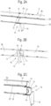
- Figuren 2A bis 2D
- mehrere Ansichten des Schiebetürbeschlages bei der Montage in einer Ausgangsposition;
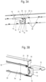
- Figuren 3A bis 3C
- mehrere Ansichten des Schiebetürbeschlages der
Figur 2 in einer verspannten Position; - Figuren 4A und 4B
- zwei Ansichten des Schiebetürbeschlages der
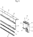
Figur 2 mit Einlegeteilen; - Figur 5
- eine Explosionsdarstellung eines Schiebetürbeschlages gemäß eines zweiten Ausführungsbeispiels;
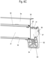
- Figuren 6A bis 6C
- mehrere Ansichten des Schiebetürbeschlages der
Figur 5 in einem verspannten Zustand; - Figuren 7A und 7B
- zwei Ansichten des Schiebetürbeschlages der
Figur 5 bei der Montage; - Figur 8
- eine Explosionsdarstellung eines dritten Ausführungsbeispiels eines erfindungsgemäßen Schiebetürbeschlages;
- Figuren 9A und 9B
- zwei Ansichten des Schiebetürbeschlages der
Figur 8 in einer montierten Position, und - Figur 10
- eine Detailansicht des Schiebetürbeschlages der
Figur 8 . - Ein Schrankmöbel 1 umfasst einen Möbelkorpus 2, der an einer Vorderseite Öffnungen aufweist, die über mehrere Schiebetüren 5 und 6 geöffnet und verschlossen werden können. Jede Schiebetür 5 und 6 ist dabei über Laufteile 4 entlang einer Laufschiene 3 verfahrbar, die an einem Oberboden des Möbelkorpus 2 fixiert ist. An einer Unterseite des Möbelkorpus 2 ist eine Führungsschiene 7 vorgesehen, die für eine Führung der Schiebetüren 5 und 6 im Bodenbereich sorgt. Die Schiebetüren 5 und 6 sind dabei in zwei unterschiedlichen, parallel zueinander liegenden, Ebenen angeordnet.
- In den
Figuren 2A bis 2D ist der Schiebetürbeschlag an dem Oberboden des Möbelkorpus 2 im Detail gezeigt. Die Laufschiene 3 umfasst zwei Profile 3a und 3b, die fluchtend zueinander angeordnet sind und den gleichen Profilquerschnitt besitzen. Die Profile 3a und 3b sind an einer Stoßstelle über eine Profilverbindung 10 miteinander verbunden. - Die Profilverbindung 10 umfasst ein Stützteil 11, das an den Profilen 3a und 3b fixiert ist. Hierfür umfasst das Stützteil 11 zwei Haken 12, die jeweils eine Öffnung in einem der Profile 3a oder 3b durchgreifen.
- Die Profile 3a und 3b umfassen eine obere horizontale Kante 30, die auf einer Oberseite des Oberbodens des Möbelkorpus 2 aufliegt. An einem Stoßbereich der Profile 3a und 3b sind beide über ein Befestigungsmittel, beispielsweise eine Schraube 8, fixiert, die eine gemeinsame Öffnung 35 an der Stirnseite der Profile 3a und 3b durchgreift. In einer alternativen Ausführungsform der Profile 3a und 3b können zur Fixierung durch Befestigungsmittel am Oberboden und Festlegung der Profile zueinander auch jeweils separate Öffnungen 36 in der horizontalen Kante 30 verwendet werden.
- Die Profile 3a und 3b bilden eine obere Laufbahn 32 und eine untere Laufbahn 33 aus, die in vertikaler Richtung übereinander in horizontaler Richtung , aber im Wesentlichen in der gleichen Ebene, angeordnet sind. Es ist auch möglich, dass die Profile 3a und 3b mehr als zwei Laufbahnen 32 und 33 aufweisen, wobei die Laufbahnen in vertikaler oder auch horizontaler Richtung versetzt angeordnet sein können.
- Wie in
Figur 2C erkennbar ist, umfasst die Profilverbindung 10 ein Spannelement 13, das relativ zu dem Stützteil 11 in vertikale Richtung bewegbar ist. Das Spannelement 13 umfasst an einer Unterseite eine Leiste 14, die die untere Laufbahn 33 an einer Unterseite untergreift und dort zur Abstützung anlegbar ist. - Wie aus
Figur 2D erkennbar ist, umfasst die Profilverbindung 10 einen Spannmechanismus mit einem verschwenkbaren Spannhebel 15, der um eine Achse 16 drehbar gelagert ist. Der Spannhebel 15 umfasst radial beabstandet zu der Achse 16 eine Kurvenführung 17, deren Oberfläche in ihrem Verlauf in einem unterschiedlichen Abstand zu der Achse 16 angeordnet ist. Der Spannhebel 15 ist dabei an dem Spannelement 13 drehbar gelagert. Das Stützteil 11 umfasst an einem unteren Ende ein Gegenlager 18, auf dem sich die Kurvenführung 17 bei einem Drehen des Spannhebels 15 abstützen kann. Ferner ist ein Rand 20 und ein linearer Abschnitt 22 des Spannhebels 15 benachbart zu einem Anschlag 21 angeordnet. Der Rand 20 dient zur Führung einer Öffnungsbewegung während eines Demontagevorgangs. Dabei läuft der Rand 20 an dem Anschlag 21 entlang und wird dazu genutzt, das Stützteil 11 und das Spannelement 13 wieder zu lösen und entgegen der Spannrichtung zu bewegen. Der an den Rand 20 anschließende lineare Abschnitt 22 begrenzt zusammen mit dem Anschlag 21 die Öffnungsbewegung des Spannhebels 15. - Zur Montage des Schiebetürbeschlages werden zunächst die beiden Profile 3a und 3b an dem Möbelkorpus 2 am Oberboden mithilfe eines Befestigungsmittels, beispielsweise einer Schraube 8, fixiert. Um die Stoßstelle der beiden Profile 3a und 3b auszurichten und zu stabilisieren, wird nun die Profilverbindung 10 unterhalb des Oberbodens montiert, wobei zunächst die Haken 12 in die Öffnungen an den Profilen 3a und 3b eingesteckt werden. Anschließend wird der Spannhebel 15 verschwenkt, insbesondere in einem Schwenkbereich zwischen 60° und 180°, wobei die Kurvenführung 17 entlang des Gegenlagers 18 bewegt wird und somit das Spannelement 13 mit der Leiste 14 in vertikale Richtung nach oben bewegt wird, bis die in den
Figuren 3A bis 3C gezeigte Position erreicht ist. In dieser Position ist das Gegenlager 18 an einer Stufe der Kurvenführung 17 angelangt, die ein weiteres Drehen des Spannhebels 15 verhindert und somit eine Endlage des Spannmechanismus definiert. Der Spannhebel 15 ist um etwa 90° gedreht worden und nun parallel zur Längsrichtung der Profile 3a und 3b ausgerichtet. - Bei der vertikalen Bewegung des Spannelementes 13 sorgen seitliche Führungsstege 19 an dem Spannelement 13, die winkelförmig oder U-förmig umgebogen sind, für eine vertikale Führung des Spannelementes 13 relativ zu dem Stützteil 11, das mit einem Rand entlang der Führungsstege 19 gehalten ist.
- Wie in
Figur 3C gezeigt ist, greift die Leiste 14 mit einer Kante unter die Laufbahn 33 und stützt somit die Stoßstelle zwischen den beiden Profilen 3a und 3b. Die Laufbahnen 32 und 33 sind nach oben konvex gewölbt ausgebildet, so dass in die konkave Aufnahme an der Unterseite der Laufbahn 33 die Kante der Leiste 14 eingreift und beim Drehen des Spannhebels 15 dort verspannt wird. Die Wegstrecke des Spannelementes 13 relativ zu dem Stützteil 11 kann in einem Bereich zwischen 0,5 mm bis 4 mm liegen. - In
Figur 4A ist die Profilverbindung 10 mit dem Profil 3a in einer Explosionsdarstellung gezeigt. Das Profil 3a, das spiegelbildlich dem Profil 3b gleicht, umfasst an einem vertikalen Abschnitt 31 Öffnungen 34, die benachbart zu der Laufbahn 32 oder 33 angeordnet sind. Die Öffnungen 34 dienen zur Montage eines stegförmigen Einlegeteils 40, das hervorstehende Vorsprünge 41 umfasst, die in die Öffnungen 34 bei der Montage einfügbar sind. Die Einlegeteile 40 werden auf oder neben die Laufbahn 32 oder 33 eingefügt, um die Last beim Überfahren der Stoßstelle durch Laufrollen oder Gleitkörper besser verteilen zu können und ein unmittelbares überfahren der Stoßstelle zu vermeiden. - Die Profilverbindung 10 ist als vormontierte Einheit nach Art eines Schnellspanners ausgebildet und kann werkzeugfrei montiert werden, wenn die Haken 12 in jeweils eine Öffnung an den Profilen 3a und 3b eingefügt werden und die Leiste 14 die Laufbahn 33 untergreift, um dann durch Verschwenken des Spannhebels 15 nach oben gegen die Unterseite der Laufbahn 33 verspannt zu werden.
- In
Figur 4B ist die montierte Position der Laufschiene 3 gezeigt. Die beiden Profile 3a und 3b sind fluchtend angeordnet, und an der Stoßstelle sind die Einlegeteile 40 benachbart zu den Laufbahnen 32 oder 33 angeordnet. - In
Figur 5 ist ein zweites Ausführungsbeispiel eines Schiebetürbeschlages gezeigt, bei dem die Profile 3a und 3b wie bei dem ersten Ausführungsbeispiel ausgebildet sind. Es wird an der Stoßstelle der Profile 3a und 3b eine modifizierte Profilverbindung 50 eingesetzt. - Die Profilverbindung 50 umfasst ein Stützteil 51, das zwei Haken 52 aufweist, die wie bei dem vorangegangenen Ausführungsbeispiel an einem vertikalen Abschnitt 31 der Profile 3a und 3b in Öffnungen einfügbar sind. An dem Stützteil 51 ist ein Spannelement 53 bewegbar gehalten, an dessen Unterseite eine Leiste 54 ausgebildet ist, die die Laufbahn 33 untergreift. An dem Spannelement 53 sind zwei umgebogene Laschen 57 vorgesehen, an denen eine Achse 56 zur drehbaren Anbringung eines Spannhebels 55 ausgebildet ist.
- In den
Figuren 6A bis 6C ist die Profilverbindung 50 in einer unverspannten Position gezeigt. Der Spannhebel 55 steht im Wesentlichen in vertikale Richtung, senkrecht zu einer Längsrichtung der Profile 3a und 3b. - In den
Figuren 7A und 7B ist die Profilverbindung 50 in einer verspannten Position gezeigt, in der der Spannhebel 55 nach oben verschwenkt wurde. Nun steht der Spannhebel 55 im Wesentlichen senkrecht in horizontale Richtung von den Profilen 3a und 3b hervor. An der Unterseite des Spannhebels 55 ist eine Kurvenführung 59 ausgebildet, die an einem Gegenlager 58 des Stützteils 51 abgestützt ist. Wird der Spannhebel 55 nach oben um etwa 90° verschwenkt, gleitet die Kurvenführung 59 an dem Gegenlager 58 entlang und bewegt die Achse 56 und somit das Spannelement 53 in vertikale Richtung nach oben, so dass die Leiste 54 gegen die Unterseite der Laufbahn 33 drückt. Dadurch sorgt die Leiste 54 für eine exakte Ausrichtung der Stege der Laufbahn 33. Die Achse 56 des Spannhebels 55 ist dabei parallel zur Längsrichtung der Profile 3a und 3b ausgerichtet. - In
Figur 8 ist ein drittes Ausführungsbeispiel einer modifizierten Profilverbindung 60 für Profile 3a und 3b gezeigt. Die Profile 3a und 3b sind wie bei den ersten Ausführungsbeispielen ausgebildet und können optional im Bereich der Stoßstelle Einlegeteile 40 aufweisen, die mit Vorsprüngen 41 in Öffnungen 34 eingesteckt werden, um die Kräfteverteilung beim Überfahren der Stoßstelle zu optimieren. - Die Profilverbindung 60 umfasst ein Stützteil 61, das wie bei den vorangegangenen Ausführungsbeispielen zwei Haken 62 aufweist, die jeweils in eine Öffnung an einem der Profile 3a oder 3b einfügbar sind, um das Stützteil 61 dort zu fixieren. An dem Stützteil 61 ist ein Spannelement 63 in vertikale Richtung bewegbar gehalten, das eine Leiste 64 aufweist, die eine Laufbahn 33 untergreift. Anders als bei den vorangegangenen Ausführungsbeispielen umfasst die Profilverbindung 60 keinen verschwenkbaren Spannhebel, sondern einen Spannmechanismus mit einer Mutter 69.
- In den
Figuren 9A und 9B ist der Stoßbereich der Profile 3a und 3b gezeigt, wobei die Profilverbindung 60 an der Rückseite der Profile 3a und 3b angeordnet ist. Die Profilverbindung 60 umfasst an dem Stützteil 61 eine hervorstehende Lasche 66, die von einer Gewindestange 67 durchgriffen ist. An dem Spannelement 63 ist eine weitere hervorstehende Lasche 65 mit einer Öffnung ausgebildet, die ebenfalls von der Gewindestange 67 durchgriffen ist. An der Gewindestange 67 ist ein Anschlagelement 68, beispielsweise eine Kontermutter, aufgeschraubt, während an der Unterseite die Mutter 69 angeordnet, beispielsweise aufgeschraubt, eingepresst oder aufgeschweißt, ist, die zum Verspannen der Profilverbindung 60 dient. Durch Drehen der Mutter 69 kann das Spannelement 63 relativ zu dem Stützteil 61 in vertikale Richtung verschoben werden, um die Leiste 64 gegen die Unterseite der Laufbahn 33 zu drücken. Auch dadurch kann der Stoßbereich zwischen den Profilen 3a und 3b stabilisiert werden. - In
Figur 10 ist die Stoßstelle mit nur einem Profil 3a gezeigt, und es ist erkennbar, dass die Leiste 64 mit der Kante gegen die Unterseite der Laufbahn 33 verspannbar ist. Das Spannelement 63 umfasst einen umgebogenen Führungssteg 70, der einen Rand des Stützteils 61 umgreift, so dass das Spannelement 63 in vertikale Richtung an dem Stützteil 61 geführt ist. - In den dargestellten Ausführungsbeispielen sind das Stützteil 11, 51 oder 61 und das Spannelement 13, 53 oder 63 jeweils aus gebogenen Metallblechen hergestellt, können aber auch aus Kunststoff oder anderen Materialien hergestellt sein. Gleiches gilt für den Spannhebel 15 oder 55.
- Die Profile 3a und 3b umfassen zwei Laufbahnen 32 und 33, von denen nur die untere Laufbahn 33 durch eine Profilverbindung 10, 50 oder 60 abgestützt ist. Es ist natürlich möglich, auch an der oberen Laufbahn 32 eine weitere Profilverbindung zur Abstützung vorzusehen. Die Biegebelastung an der unteren Laufbahn 33 ist ohne Profilverbindung allerdings größer als an der stabileren oberen Laufbahn, die benachbart zu einer Stirnseite des Oberbodens angeordnet ist. Dadurch kann auch die Vorsehung nur einer Profilverbindung 10, 50 oder 60 für die untere Laufbahn 33 ausreichend sein.
- Die Profile 3a und 3b sind aus einem gebogenen Stahlblech hergestellt. Es ist auch möglich, eine Profilverbindung 10, 50 oder 60 für extrudierte Profile einzusetzen.
- Zudem kann der Schiebetürbeschlag statt an einem Möbelkorpus 2 auch zur Aufhängung von Schiebetüren an Raumteilern eingesetzt werden.
-
- 1
- Schrankmöbel
- 2
- Möbelkorpus
- 3
- Laufschiene
- 3a, 3b
- Profil
- 4
- Laufteil
- 5
- Schiebetür
- 6
- Schiebetür
- 7
- Führungsschiene
- 8
- Schraube
- 10
- Profilverbindung
- 11
- Stützteil
- 12
- Haken
- 13
- Spannelement
- 14
- Leiste
- 15
- Spannhebel
- 16
- Achse
- 17
- Kurvenführung
- 18
- Gegenlager
- 19
- Führungssteg
- 20
- Rand
- 21
- Anschlag
- 22
- Abschnitt
- 30
- Kante
- 31
- vertikaler Abschnitt
- 32
- Laufbahn
- 33
- Laufbahn
- 34
- Öffnung
- 35
- Öffnung
- 36
- Öffnung
- 40
- Einlegeteil
- 41
- Vorsprung
- 50
- Profilverbindung
- 51
- Stützteil
- 52
- Haken
- 53
- Spannelement
- 54
- Leiste
- 55
- Spannhebel
- 56
- Achse
- 57
- Lasche
- 58
- Gegenlager
- 59
- Kurvenführung
- 60
- Profilverbindung
- 61
- Stützteil
- 62
- Haken
- 63
- Spannelement
- 64
- Leiste
- 65
- Lasche
- 66
- Lasche
- 67
- Gewindestange
- 68
- Anschlagelement
- 69
- Mutter
- 70
- Führungssteg
Claims (14)
- Schiebetürbeschlag mit zwei an einer Stoßstelle über eine Profilverbindung (10, 50, 60) miteinander verbundenen Profilen (3a, 3b), die mindestens eine Laufbahn (32, 33) für Rollen oder Gleitkörper eines verfahrbaren Laufteils ausbilden, wobei die Profilverbindung (10, 50, 60) ein an den Profilen (3a, 3b) festgelegtes Stützteil (11, 51, 61) und ein über einen Spannmechanismus relativ zu dem Stützteil (11, 51, 61) bewegbares Spannelement (13, 53, 63) aufweist, das die beiden Profile (3a, 3b) zu dem Stützteil (11, 51, 61) hin vorspannt, dadurch gekennzeichnet, dass die Profile (3a, 3b) mindestens zwei in der Einbauposition übereinander liegende Laufbahnen (32, 33) aufweisen und das Spannelement (13, 53, 63) an einer Unterseite der unteren Laufbahn (33) anliegt.
- Schiebetürbeschlag nach Anspruch 1, dadurch gekennzeichnet, dass das Spannelement (13, 53, 63) relativ zu dem Stützteil (11, 51, 61) über den Spannmechanismus in der eingebauten Position in vertikale Richtung bewegbar ist.
- Schiebetürbeschlag nach Anspruch 1 oder 2, dadurch gekennzeichnet, dass das Spannelement (13, 53, 63) an den beiden Profilen (3a, 3b) auf der zu der mindestens einen Laufbahn (32, 33) gegenüberliegenden Seite anliegt.
- Schiebetürbeschlag nach Anspruch 3, dadurch gekennzeichnet, dass das Spannelement (13, 53, 63) eine hervorstehende Leiste (14, 54, 64) aufweist, die die Laufbahn (32, 33) untergreift.
- Schiebetürbeschlag nach einem der vorhergehenden Ansprüche, dadurch gekennzeichnet, dass das Stützteil (11, 51, 61) zwei Haken (12, 52, 62) aufweist und jeweils ein Haken (12, 52, 62) eine Öffnung an einem der beiden Profile (3a, 3b) durchgreift.
- Schiebetürbeschlag nach einem der vorhergehenden Ansprüche, dadurch gekennzeichnet, dass das Spannelement (13, 53) über einen verschwenkbaren Spannhebel (15, 55) relativ zu dem Stützteil (11, 51) bewegbar ist.
- Schiebetürbeschlag nach Anspruch 6, dadurch gekennzeichnet, dass an dem Spannhebel (15, 55) eine Kurvenführung (17, 59) ausgebildet ist, die an einem Gegenlager (18, 58) bewegbar ist, um das Spannelement (13, 53) relativ zu dem Stützteil (11, 51) zu bewegen.
- Schiebetürbeschlag nach Anspruch 6 oder 7, dadurch gekennzeichnet, dass eine Drehachse (16, 56) des Spannhebels (15, 55) in Längsrichtung der Profile (3a, 3b) oder senkrecht zur Längsrichtung der Profile (3a, 3b) ausgerichtet ist.
- Schiebetürbeschlag nach einem der Ansprüche 1 bis 5, dadurch gekennzeichnet, dass der Spannmechanismus eine Gewindestange (67) und eine an der Gewindestange (67) angeordnete, beispielsweise aufgeschraubte, eingepresste oder aufgeschweißte, Mutter (69) umfasst.
- Schiebetürbeschlag nach einem der vorhergehenden Ansprüche, dadurch gekennzeichnet, dass an der Stoßstelle ein Einlegeteil (40) an oder auf einer Laufbahn (32, 33) der beiden Profile (3a, 3b) eingelegt ist.
- Möbel (1) mit einem Möbelkorpus (2), an dem ein Schiebetürbeschlag nach einem der vorhergehenden Ansprüche montiert ist.
- Verfahren zur Montage eines Schiebetürbeschlages mit den folgenden Schritten:- Festlegen eines ersten Profils (3a) an einem Möbelkorpus;- Festlegen eines zweiten Profils (3b) in Verlängerung des ersten Profils (3a) an dem Möbelkorpus (2);- Fixieren einer Profilverbindung (10, 50, 60) an einer Stoßstelle des ersten und des zweiten Profils (3a, 3b);- wobei die Profilverbindung (10, 50, 60) ein an den Profilen (3a, 3b) festgelegtes Stützteil (11, 51, 61) und einen über einen Spannmechanismus relativ zu dem Stützteil (11, 51, 61) bewegbares Spannelement (13, 53, 63) aufweist, das beim Fixieren an den Profilen (3a, 3b) relativ zu dem Stützteil (11, 51, 61) verspannt wird,dadurch gekennzeichnet, dass die Profile (3a, 3b) mindestens zwei in der Einbauposition übereinander liegende Laufbahnen (32, 33) aufweisen und das Spannelement (13, 53, 63) an einer Unterseite der unteren Laufbahn (33) anliegt.
- Verfahren nach Anspruch 12, dadurch gekennzeichnet, dass das Verspannen des Spannelementes (13, 53, 63) relativ zu dem Stützteil (11, 51, 61) werkzeugfrei über einen verschwenkbaren Hebel (15, 55) oder eine drehbare Mutter (69) erfolgt.
- Verfahren nach Anspruch 12 oder 13, dadurch gekennzeichnet, dass das Spannelement (13, 53, 63) beim Fixieren an den Profilen (3a, 3b) relativ zu dem Stützteil (11, 51, 61) in einer vertikalen Richtung verspannt wird.
Applications Claiming Priority (2)
| Application Number | Priority Date | Filing Date | Title |
|---|---|---|---|
| DE102020132044.2A DE102020132044A1 (de) | 2020-12-02 | 2020-12-02 | Schiebetürbeschlag und Verfahren zur Montage eines Schiebetürbeschlages |
| PCT/EP2021/083763 WO2022117645A1 (de) | 2020-12-02 | 2021-12-01 | Schiebetürbeschlag und verfahren zur montage eines schiebetürbeschlages |
Publications (2)
| Publication Number | Publication Date |
|---|---|
| EP4256159A1 EP4256159A1 (de) | 2023-10-11 |
| EP4256159B1 true EP4256159B1 (de) | 2024-09-11 |
Family
ID=79185532
Family Applications (1)
| Application Number | Title | Priority Date | Filing Date |
|---|---|---|---|
| EP21835592.3A Active EP4256159B1 (de) | 2020-12-02 | 2021-12-01 | Schiebetürbeschlag und verfahren zur montage eines schiebetürbeschlages |
Country Status (4)
| Country | Link |
|---|---|
| EP (1) | EP4256159B1 (de) |
| DE (1) | DE102020132044A1 (de) |
| PL (1) | PL4256159T3 (de) |
| WO (1) | WO2022117645A1 (de) |
Families Citing this family (1)
| Publication number | Priority date | Publication date | Assignee | Title |
|---|---|---|---|---|
| DE102022121033A1 (de) * | 2022-08-19 | 2024-02-22 | Hettich-Heinze Gmbh & Co. Kg | Schienenanordnung und Schiebetürbeschlag |
Family Cites Families (11)
| Publication number | Priority date | Publication date | Assignee | Title |
|---|---|---|---|---|
| US1945332A (en) * | 1931-05-25 | 1934-01-30 | Stanley Works | Track support |
| US2649612A (en) * | 1949-09-08 | 1953-08-25 | Stanley Works | Track and bracket |
| US3431585A (en) * | 1967-02-27 | 1969-03-11 | Lawrence Brothers | Track supports |
| ES2092180T3 (es) * | 1992-06-04 | 1996-11-16 | Karl Haab | Carril. |
| DE29901506U1 (de) * | 1999-01-29 | 1999-05-12 | Mabeg Kreuschner GmbH & Co. KG, 59494 Soest | Metallbauelement |
| DE10204349B4 (de) * | 2002-02-01 | 2012-04-05 | Volkswagen Ag | Führungsschiene für eine Tür eines Kraftfahrzeugs sowie Verfahren zur Herstellung einer derartigen Führungsschiene |
| DE102012101216B4 (de) | 2012-02-15 | 2025-06-12 | Hettich-Heinze Gmbh & Co. Kg | Schiebetürbeschlag |
| DE102014113930A1 (de) | 2014-09-25 | 2016-03-31 | Allsafe Jungfalk Gmbh & Co. Kg | Vorrichtung zum Festlegen von Ladungsgegenständen |
| DE202018106540U1 (de) | 2018-11-19 | 2018-12-06 | Rennerich Gmbh | Führungsvorrichtung |
| DE102019101334A1 (de) | 2019-01-18 | 2020-07-23 | Hettich-Heinze Gmbh & Co. Kg | Schiebetürbeschlag und Möbel |
| DE102019121404A1 (de) | 2019-08-08 | 2021-02-11 | Hettich-Heinze Gmbh & Co. Kg | Schiebetürbeschlag, Möbel und Verfahren zur Montage eines Schiebetürbeschlages |
-
2020
- 2020-12-02 DE DE102020132044.2A patent/DE102020132044A1/de active Pending
-
2021
- 2021-12-01 EP EP21835592.3A patent/EP4256159B1/de active Active
- 2021-12-01 PL PL21835592.3T patent/PL4256159T3/pl unknown
- 2021-12-01 WO PCT/EP2021/083763 patent/WO2022117645A1/de not_active Ceased
Also Published As
| Publication number | Publication date |
|---|---|
| EP4256159A1 (de) | 2023-10-11 |
| WO2022117645A1 (de) | 2022-06-09 |
| PL4256159T3 (pl) | 2025-03-03 |
| DE102020132044A1 (de) | 2022-06-02 |
Similar Documents
| Publication | Publication Date | Title |
|---|---|---|
| EP4010554B1 (de) | Schiebetürbeschlag, möbel und verfahren zur montage eines schiebetürbeschlages | |
| EP0945577B2 (de) | Verwendung einer Profilschiene zum Abstützen von Fenster- oder Türrahmen | |
| DE10002075C2 (de) | Profilrahmen | |
| EP0862873B1 (de) | Befestigungsbeschlag und Schublade mit einem solchen Beschlag | |
| EP3899177B1 (de) | Führungssystem zur führung wenigstens eines bewegbar gelagerten türflügels | |
| EP3875717B1 (de) | Laufschiene in form eines gewalzten blechprofils | |
| EP4256159B1 (de) | Schiebetürbeschlag und verfahren zur montage eines schiebetürbeschlages | |
| WO2008110248A1 (de) | Vorrichtung mit einem montageeinsatz zur befestigung von beschlagteilen an hohlprofilen sowie verfahren zur anbringung des montageeinsatzes an dem hohlprofil | |
| EP2700778A1 (de) | Vorrichtung zur verfahrbaren Abstützung einer Platte | |
| EP0826850B1 (de) | Fassadenunterkonstruktion | |
| EP3211164B1 (de) | Schiebetürsystem | |
| EP1967108B1 (de) | Duschabtrennung | |
| EP3381856A1 (de) | Befestigungsset mit zumindest einem befestigungselement zum befestigen einer schiene einer aufzugsanlage in einem aufzugsschacht | |
| AT526489B1 (de) | Oberer Querholm für eine Duschabtrennung | |
| WO2017207796A1 (de) | Verfahren und vorrichtung zum ausrichten von fenster- oder türrahmen | |
| DE19744832A1 (de) | Anordnung für den Einbau eines Fensterrahmens | |
| EP3816383B1 (de) | Schiebetüranordnung | |
| DE202022104870U1 (de) | Glasträgerelement mit montageseitig und fallseitig verschiebbaren Innenkeilen | |
| EP0698169A1 (de) | Torblatt | |
| DE102011008765A1 (de) | Profilanordnung, Rahmen und Rahmenanordnung | |
| EP3286395A1 (de) | Beschlag für eine schiebetür und verfahren zur montage eines führungsbeschlages | |
| DE20219264U1 (de) | Vorrichtung zum Verbinden des Befestigungsbereichs einer Führungsschiene mit dem Türboden einer Fahrzeugtür | |
| EP3822440B1 (de) | Schiebetürbeschlag, möbel und verfahren zur montage eines schiebetürbeschlages | |
| DE102011010832A1 (de) | Befestigung für Sonnenkollektoren | |
| DE9407718U1 (de) | Mittel zum Befestigen und Verbinden zweier engbenachbart zueinander angeordneter Langprofile |
Legal Events
| Date | Code | Title | Description |
|---|---|---|---|
| STAA | Information on the status of an ep patent application or granted ep patent |
Free format text: STATUS: UNKNOWN |
|
| STAA | Information on the status of an ep patent application or granted ep patent |
Free format text: STATUS: THE INTERNATIONAL PUBLICATION HAS BEEN MADE |
|
| PUAI | Public reference made under article 153(3) epc to a published international application that has entered the european phase |
Free format text: ORIGINAL CODE: 0009012 |
|
| STAA | Information on the status of an ep patent application or granted ep patent |
Free format text: STATUS: REQUEST FOR EXAMINATION WAS MADE |
|
| 17P | Request for examination filed |
Effective date: 20230628 |
|
| AK | Designated contracting states |
Kind code of ref document: A1 Designated state(s): AL AT BE BG CH CY CZ DE DK EE ES FI FR GB GR HR HU IE IS IT LI LT LU LV MC MK MT NL NO PL PT RO RS SE SI SK SM TR |
|
| DAV | Request for validation of the european patent (deleted) | ||
| DAX | Request for extension of the european patent (deleted) | ||
| GRAP | Despatch of communication of intention to grant a patent |
Free format text: ORIGINAL CODE: EPIDOSNIGR1 |
|
| STAA | Information on the status of an ep patent application or granted ep patent |
Free format text: STATUS: GRANT OF PATENT IS INTENDED |
|
| INTG | Intention to grant announced |
Effective date: 20240430 |
|
| GRAS | Grant fee paid |
Free format text: ORIGINAL CODE: EPIDOSNIGR3 |
|
| P01 | Opt-out of the competence of the unified patent court (upc) registered |
Free format text: CASE NUMBER: APP_38806/2024 Effective date: 20240628 |
|
| GRAA | (expected) grant |
Free format text: ORIGINAL CODE: 0009210 |
|
| STAA | Information on the status of an ep patent application or granted ep patent |
Free format text: STATUS: THE PATENT HAS BEEN GRANTED |
|
| AK | Designated contracting states |
Kind code of ref document: B1 Designated state(s): AL AT BE BG CH CY CZ DE DK EE ES FI FR GB GR HR HU IE IS IT LI LT LU LV MC MK MT NL NO PL PT RO RS SE SI SK SM TR |
|
| REG | Reference to a national code |
Ref country code: GB Ref legal event code: FG4D Free format text: NOT ENGLISH |
|
| REG | Reference to a national code |
Ref country code: CH Ref legal event code: EP |
|
| REG | Reference to a national code |
Ref country code: DE Ref legal event code: R096 Ref document number: 502021005151 Country of ref document: DE |
|
| REG | Reference to a national code |
Ref country code: IE Ref legal event code: FG4D Free format text: LANGUAGE OF EP DOCUMENT: GERMAN |
|
| REG | Reference to a national code |
Ref country code: LT Ref legal event code: MG9D |
|
| PG25 | Lapsed in a contracting state [announced via postgrant information from national office to epo] |
Ref country code: NO Free format text: LAPSE BECAUSE OF FAILURE TO SUBMIT A TRANSLATION OF THE DESCRIPTION OR TO PAY THE FEE WITHIN THE PRESCRIBED TIME-LIMIT Effective date: 20241211 |
|
| REG | Reference to a national code |
Ref country code: NL Ref legal event code: MP Effective date: 20240911 |
|
| PG25 | Lapsed in a contracting state [announced via postgrant information from national office to epo] |
Ref country code: GR Free format text: LAPSE BECAUSE OF FAILURE TO SUBMIT A TRANSLATION OF THE DESCRIPTION OR TO PAY THE FEE WITHIN THE PRESCRIBED TIME-LIMIT Effective date: 20241212 Ref country code: FI Free format text: LAPSE BECAUSE OF FAILURE TO SUBMIT A TRANSLATION OF THE DESCRIPTION OR TO PAY THE FEE WITHIN THE PRESCRIBED TIME-LIMIT Effective date: 20240911 |
|
| PG25 | Lapsed in a contracting state [announced via postgrant information from national office to epo] |
Ref country code: BG Free format text: LAPSE BECAUSE OF FAILURE TO SUBMIT A TRANSLATION OF THE DESCRIPTION OR TO PAY THE FEE WITHIN THE PRESCRIBED TIME-LIMIT Effective date: 20240911 |
|
| PG25 | Lapsed in a contracting state [announced via postgrant information from national office to epo] |
Ref country code: LV Free format text: LAPSE BECAUSE OF FAILURE TO SUBMIT A TRANSLATION OF THE DESCRIPTION OR TO PAY THE FEE WITHIN THE PRESCRIBED TIME-LIMIT Effective date: 20240911 |
|
| PG25 | Lapsed in a contracting state [announced via postgrant information from national office to epo] |
Ref country code: HR Free format text: LAPSE BECAUSE OF FAILURE TO SUBMIT A TRANSLATION OF THE DESCRIPTION OR TO PAY THE FEE WITHIN THE PRESCRIBED TIME-LIMIT Effective date: 20240911 |
|
| PG25 | Lapsed in a contracting state [announced via postgrant information from national office to epo] |
Ref country code: RS Free format text: LAPSE BECAUSE OF FAILURE TO SUBMIT A TRANSLATION OF THE DESCRIPTION OR TO PAY THE FEE WITHIN THE PRESCRIBED TIME-LIMIT Effective date: 20241211 Ref country code: ES Free format text: LAPSE BECAUSE OF FAILURE TO SUBMIT A TRANSLATION OF THE DESCRIPTION OR TO PAY THE FEE WITHIN THE PRESCRIBED TIME-LIMIT Effective date: 20240911 |
|
| PG25 | Lapsed in a contracting state [announced via postgrant information from national office to epo] |
Ref country code: RS Free format text: LAPSE BECAUSE OF FAILURE TO SUBMIT A TRANSLATION OF THE DESCRIPTION OR TO PAY THE FEE WITHIN THE PRESCRIBED TIME-LIMIT Effective date: 20241211 Ref country code: NO Free format text: LAPSE BECAUSE OF FAILURE TO SUBMIT A TRANSLATION OF THE DESCRIPTION OR TO PAY THE FEE WITHIN THE PRESCRIBED TIME-LIMIT Effective date: 20241211 Ref country code: LV Free format text: LAPSE BECAUSE OF FAILURE TO SUBMIT A TRANSLATION OF THE DESCRIPTION OR TO PAY THE FEE WITHIN THE PRESCRIBED TIME-LIMIT Effective date: 20240911 Ref country code: HR Free format text: LAPSE BECAUSE OF FAILURE TO SUBMIT A TRANSLATION OF THE DESCRIPTION OR TO PAY THE FEE WITHIN THE PRESCRIBED TIME-LIMIT Effective date: 20240911 Ref country code: GR Free format text: LAPSE BECAUSE OF FAILURE TO SUBMIT A TRANSLATION OF THE DESCRIPTION OR TO PAY THE FEE WITHIN THE PRESCRIBED TIME-LIMIT Effective date: 20241212 Ref country code: FI Free format text: LAPSE BECAUSE OF FAILURE TO SUBMIT A TRANSLATION OF THE DESCRIPTION OR TO PAY THE FEE WITHIN THE PRESCRIBED TIME-LIMIT Effective date: 20240911 Ref country code: ES Free format text: LAPSE BECAUSE OF FAILURE TO SUBMIT A TRANSLATION OF THE DESCRIPTION OR TO PAY THE FEE WITHIN THE PRESCRIBED TIME-LIMIT Effective date: 20240911 Ref country code: BG Free format text: LAPSE BECAUSE OF FAILURE TO SUBMIT A TRANSLATION OF THE DESCRIPTION OR TO PAY THE FEE WITHIN THE PRESCRIBED TIME-LIMIT Effective date: 20240911 |
|
| PG25 | Lapsed in a contracting state [announced via postgrant information from national office to epo] |
Ref country code: NL Free format text: LAPSE BECAUSE OF FAILURE TO SUBMIT A TRANSLATION OF THE DESCRIPTION OR TO PAY THE FEE WITHIN THE PRESCRIBED TIME-LIMIT Effective date: 20240911 |
|
| PG25 | Lapsed in a contracting state [announced via postgrant information from national office to epo] |
Ref country code: PT Free format text: LAPSE BECAUSE OF FAILURE TO SUBMIT A TRANSLATION OF THE DESCRIPTION OR TO PAY THE FEE WITHIN THE PRESCRIBED TIME-LIMIT Effective date: 20250113 Ref country code: IS Free format text: LAPSE BECAUSE OF FAILURE TO SUBMIT A TRANSLATION OF THE DESCRIPTION OR TO PAY THE FEE WITHIN THE PRESCRIBED TIME-LIMIT Effective date: 20250111 |
|
| PG25 | Lapsed in a contracting state [announced via postgrant information from national office to epo] |
Ref country code: RO Free format text: LAPSE BECAUSE OF FAILURE TO SUBMIT A TRANSLATION OF THE DESCRIPTION OR TO PAY THE FEE WITHIN THE PRESCRIBED TIME-LIMIT Effective date: 20240911 Ref country code: SM Free format text: LAPSE BECAUSE OF FAILURE TO SUBMIT A TRANSLATION OF THE DESCRIPTION OR TO PAY THE FEE WITHIN THE PRESCRIBED TIME-LIMIT Effective date: 20240911 |
|
| PG25 | Lapsed in a contracting state [announced via postgrant information from national office to epo] |
Ref country code: EE Free format text: LAPSE BECAUSE OF FAILURE TO SUBMIT A TRANSLATION OF THE DESCRIPTION OR TO PAY THE FEE WITHIN THE PRESCRIBED TIME-LIMIT Effective date: 20240911 |
|
| PG25 | Lapsed in a contracting state [announced via postgrant information from national office to epo] |
Ref country code: CZ Free format text: LAPSE BECAUSE OF FAILURE TO SUBMIT A TRANSLATION OF THE DESCRIPTION OR TO PAY THE FEE WITHIN THE PRESCRIBED TIME-LIMIT Effective date: 20240911 |
|
| PG25 | Lapsed in a contracting state [announced via postgrant information from national office to epo] |
Ref country code: SK Free format text: LAPSE BECAUSE OF FAILURE TO SUBMIT A TRANSLATION OF THE DESCRIPTION OR TO PAY THE FEE WITHIN THE PRESCRIBED TIME-LIMIT Effective date: 20240911 |
|
| REG | Reference to a national code |
Ref country code: DE Ref legal event code: R097 Ref document number: 502021005151 Country of ref document: DE |
|
| PG25 | Lapsed in a contracting state [announced via postgrant information from national office to epo] |
Ref country code: MC Free format text: LAPSE BECAUSE OF FAILURE TO SUBMIT A TRANSLATION OF THE DESCRIPTION OR TO PAY THE FEE WITHIN THE PRESCRIBED TIME-LIMIT Effective date: 20240911 |
|
| PG25 | Lapsed in a contracting state [announced via postgrant information from national office to epo] |
Ref country code: DK Free format text: LAPSE BECAUSE OF FAILURE TO SUBMIT A TRANSLATION OF THE DESCRIPTION OR TO PAY THE FEE WITHIN THE PRESCRIBED TIME-LIMIT Effective date: 20240911 |
|
| PLBE | No opposition filed within time limit |
Free format text: ORIGINAL CODE: 0009261 |
|
| STAA | Information on the status of an ep patent application or granted ep patent |
Free format text: STATUS: NO OPPOSITION FILED WITHIN TIME LIMIT |
|
| PG25 | Lapsed in a contracting state [announced via postgrant information from national office to epo] |
Ref country code: LU Free format text: LAPSE BECAUSE OF NON-PAYMENT OF DUE FEES Effective date: 20241201 |
|
| 26N | No opposition filed |
Effective date: 20250612 |
|
| PG25 | Lapsed in a contracting state [announced via postgrant information from national office to epo] |
Ref country code: SE Free format text: LAPSE BECAUSE OF FAILURE TO SUBMIT A TRANSLATION OF THE DESCRIPTION OR TO PAY THE FEE WITHIN THE PRESCRIBED TIME-LIMIT Effective date: 20240911 |
|
| REG | Reference to a national code |
Ref country code: BE Ref legal event code: MM Effective date: 20241231 |
|
| PG25 | Lapsed in a contracting state [announced via postgrant information from national office to epo] |
Ref country code: BE Free format text: LAPSE BECAUSE OF NON-PAYMENT OF DUE FEES Effective date: 20241231 |
|
| PG25 | Lapsed in a contracting state [announced via postgrant information from national office to epo] |
Ref country code: FR Free format text: LAPSE BECAUSE OF NON-PAYMENT OF DUE FEES Effective date: 20241231 |
|
| PG25 | Lapsed in a contracting state [announced via postgrant information from national office to epo] |
Ref country code: IE Free format text: LAPSE BECAUSE OF NON-PAYMENT OF DUE FEES Effective date: 20241201 |
|
| REG | Reference to a national code |
Ref country code: CH Ref legal event code: U11 Free format text: ST27 STATUS EVENT CODE: U-0-0-U10-U11 (AS PROVIDED BY THE NATIONAL OFFICE) Effective date: 20260101 |
|
| PGFP | Annual fee paid to national office [announced via postgrant information from national office to epo] |
Ref country code: AT Payment date: 20260113 Year of fee payment: 5 |
|
| PGFP | Annual fee paid to national office [announced via postgrant information from national office to epo] |
Ref country code: TR Payment date: 20251127 Year of fee payment: 5 |
|
| PGFP | Annual fee paid to national office [announced via postgrant information from national office to epo] |
Ref country code: PL Payment date: 20251118 Year of fee payment: 5 |
|
| PG25 | Lapsed in a contracting state [announced via postgrant information from national office to epo] |
Ref country code: CY Free format text: LAPSE BECAUSE OF FAILURE TO SUBMIT A TRANSLATION OF THE DESCRIPTION OR TO PAY THE FEE WITHIN THE PRESCRIBED TIME-LIMIT; INVALID AB INITIO Effective date: 20211201 |
|
| PGFP | Annual fee paid to national office [announced via postgrant information from national office to epo] |
Ref country code: DE Payment date: 20251222 Year of fee payment: 5 |
|
| PGFP | Annual fee paid to national office [announced via postgrant information from national office to epo] |
Ref country code: IT Payment date: 20251231 Year of fee payment: 5 |
|
| PGFP | Annual fee paid to national office [announced via postgrant information from national office to epo] |
Ref country code: CH Payment date: 20260101 Year of fee payment: 5 |