EP4256165B1 - Procédé de forage en tunnel et d'exploitation minière à l'aide d'une maille de sondage pré-conditionnée - Google Patents
Procédé de forage en tunnel et d'exploitation minière à l'aide d'une maille de sondage pré-conditionnée Download PDFInfo
- Publication number
- EP4256165B1 EP4256165B1 EP21841164.3A EP21841164A EP4256165B1 EP 4256165 B1 EP4256165 B1 EP 4256165B1 EP 21841164 A EP21841164 A EP 21841164A EP 4256165 B1 EP4256165 B1 EP 4256165B1
- Authority
- EP
- European Patent Office
- Prior art keywords
- region
- projectile
- projectiles
- geologic material
- geologic
- Prior art date
- Legal status (The legal status is an assumption and is not a legal conclusion. Google has not performed a legal analysis and makes no representation as to the accuracy of the status listed.)
- Active
Links
Images











Classifications
-
- E—FIXED CONSTRUCTIONS
- E21—EARTH OR ROCK DRILLING; MINING
- E21B—EARTH OR ROCK DRILLING; OBTAINING OIL, GAS, WATER, SOLUBLE OR MELTABLE MATERIALS OR A SLURRY OF MINERALS FROM WELLS
- E21B7/00—Special methods or apparatus for drilling
- E21B7/007—Drilling by use of explosives
-
- E—FIXED CONSTRUCTIONS
- E21—EARTH OR ROCK DRILLING; MINING
- E21C—MINING OR QUARRYING
- E21C37/00—Other methods or devices for dislodging with or without loading
- E21C37/005—Other methods or devices for dislodging with or without loading by projectiles
Definitions
- US 4004642 A relates to a tround terra-drill processes and apparatus;
- US 2016/362936 A1 relates to a ram accelerator system with endcap;
- GB 1371297 A relates to excavation of rock;
- US 3623771 A relates to a drill-and-blast excavating apparatus and method.
- the word “may” is used in a permissive sense (i.e., meaning having the potential to) rather than the mandatory sense (i.e., meaning must).
- the words “include”, “including”, and “includes” mean “including, but not limited to”.
- Described in this disclosure are techniques that may enable generally continuous mining, tunneling, and boring operations, which may improve efficiency over conventional techniques.
- projectiles are accelerated into the workface.
- a ram accelerator assembly may use pressurized gas to accelerate the projectiles using a ram effect caused by interaction between exterior features of the projectile and interior features of a tube or other conduit of the ram accelerator assembly.
- the accelerated projectiles may achieve a high velocity that may enable the projectiles to break or otherwise degrade the geologic material that is impacted.
- the compressive force may interact with a void created by a previous projectile impact, which may define a free face that allows the shockwave from a subsequent operation to be reflected (e.g., a rarefaction wave).
- the resulting tension force may more readily break rock or other geologic material, when compared to use of compressive forces alone, improving the rate of penetration of the subsequent projectile impacts or tunneling operations. Additionally, debris from the subsequent projectile impacts or tunneling operations may be displaced into the voids formed by the first projectile impact(s).
- one or more projectiles may be accelerated into contact with an interior region of a workface, such as a central region enclosed by a perimeter region. Interaction(s) between the projectile(s) and the geologic material may displace the geologic material to form voids.
- a cutting tool, reaming tool, impact tool, or other type of tool used to displace geologic material, or one or more additional projectiles may contact the workface, such as to extend a shaft or tunnel.
- an interaction between a cutting tool or additional projectile(s) and the geologic material would typically apply a compressive force to the geologic material to displace the geologic material at or near the point of contact.
- compressive force(s) from the cutting tool or additional projectile(s) may interact with the void(s) formed using the first projectile(s) to form a tension force.
- the resulting tension force may more readily break rock or other geologic material, with a greater rate of penetration when compared to compressive forces alone.
- Debris from the subsequent projectile impacts or tunneling operations may be displaced into the voids formed by the first projectile impact(s).
- a portion of a conveying system such as a collection plate or conveyor belt, may be positioned in a void created by an initial projectile impact to enable debris from subsequent projectile impacts or tunneling operations to fall into contact with the conveying system for transport away from the workface.
- a perimeter region of the geologic material may be pre-conditioned by forming one or more voids within the region.
- Pre-conditioning the region may include use of one or more projectile impacts, or in some cases, a preconditioning tool such as a water jet, drill, cutting tool, or other similar tools.
- the projectile impacts or other tools may form one or more voids that define a perimeter of a region of geologic material. Subsequent projectile impacts or tunneling operations that contact geologic material that is within the perimeter may cause compressive forces, which interact with the voids at the perimeter to form tension forces.
- the voids that define the perimeter may limit the breakage of geologic material outside of the perimeter, enabling the tunnel or shaft to be provided with a controlled cross-sectional shape. Additionally, the formation of voids at the perimeter of a region of geologic material may improve the rate of penetration of subsequent projectile impacts or tunneling operations due to the resulting tension forces more readily breaking rock or other material when compared to compressive forces.
- an impact between a projectile and the geologic material may cause propagation of an acoustic signal through at least a portion of the geologic material.
- An acoustic detector or other device may be used to determine data indicative of the acoustic signal, which may be analyzed, such as by using one or more computing devices, to determine characteristics of the geologic material based on transmission of the acoustic signal. For example, the manner in which the acoustic signal propagates through different regions of geologic material may be used to determine a porosity, hardness, or other characteristics of the geologic material. Based on the determined characteristics, one or more projectile characteristics or firing characteristics for a subsequent projectile impact may be determined.
- a projectile having a steel body and tapered shape, or another type of high-density body may be used.
- a projectile having a concrete body and a broader shape may be used.
- the projectile may be accelerated using selected types and quantities of propellant materials to provide the projectile with a target velocity. For example, accelerating a projectile to a ram velocity using a pressurized gas may affect the manner in which the projectile interacts with the workface and the shape of a crater that is formed, when compared to an impact by a projectile having a lower velocity.
- a projectile impact may be omitted and one or more other cutting tools, reaming tools, impact tools, or other tools to displace geologic material may be used.
- a cutting tool may be used to displace the soft or porous material without use of a subsequent projectile impact.
- a cutting tool may be used in conjunction with an acoustic sensor, a time of flight sensor, one or more cameras, vibration sensors associated with the cutting tool, or other types of sensors, to determine characteristics of the geologic material that is contacted using the cutting tool.
- the amount of debris produced during an interaction between a cutting tool and the geologic material may indicate characteristics of the geologic material, such as hardness or porosity.
- characteristics of the geologic material such as hardness or porosity.
- the presence of hard rock or other similar material may be determined, and a subsequent projectile impact may be used to weaken the hard material.
- operation of the cutting tool may continue without use of projectile impacts.
- the presence of hard or non-porous material is determined, either using sensors associated with a cutting tool or an acoustic signal generated by a previous projectile impact
- the number of projectile impacts used and the locations of the projectile impacts may be determined based on characteristics of geologic material. For example, projectile impacts may be selectively used to target regions of hard rock or veins of ore to be extracted, while regions of softer or more porous material may be contacted with a cutting tool without first impacting those regions with a projectile.
- combinations of projectile impacts, pre-conditioning tools, and cutting, reaming, impact, or other material displacement tools may be used to sequentially remove different regions of geologic material from a larger region. For example, at a first time, one or more projectile impacts may be used to weaken a first region of geologic material. Subsequent projectile impacts or cutting tools may then be used to degrade or displace geologic material from the first region, which may be conveyed away from the workface. In some cases, the void created by this operation may be used to position a collection or conveying system to remove debris, to place cutting tools, other types of material displacement tools, or projectile launching systems into the void, for subsequent operations, and so forth.
- additional projectile impacts, cutting or displacement tools, or both projectile impacts and cutting or displacement tools may be used to remove a second region of geologic material adjacent to the void created at the first time. This process may be repeated to sequentially remove regions of geologic material until a space having a desired shape is formed.
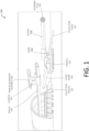
- FIG. 1 depicts an implementation of a system 100 that may be used for generally continuous tunneling, boring, or mining operations.
- the system 100 may include a plurality of vehicles or other types of assemblies that may be moved relative to a workface, such as the end of a tunnel or shaft.
- each assembly may be moved separately from other assemblies.
- each assembly and the operation thereof may be controlled remotely, such as through use of one or more computing devices located remote from a site where a tunneling, boring, or mining operation is performed.
- Computing devices may communicate with controllers that are associated with various components of the system 100, such as to cause acceleration of projectiles into a workface, actuation of a cutting tool, collection of debris, and so forth.
- a first assembly of the system 100 may include a ram accelerator assembly 102.
- the ram accelerator assembly 102 may be used to accelerate projectiles into a workface, such as the end of a tunnel or shaft to be extended.
- the ram accelerator assembly 102 may include one or more chambers for containing projectiles and propellant materials.
- a first chamber may include a combustible material, such as diesel fuel, natural gas, or other types of material that may be ignited to apply a force to a projectile within a second chamber.
- the propellant material may include one or more gas generating materials.
- the propellant material may include one or more explosive materials.
- a system may include equipment for performing high pressure electrolysis to create hydrogen and oxygen for use accelerating projectiles, reducing or eliminating the need to supply a ram accelerator assembly 102 with a separate source of propellant material.
- multiple types of propellant materials may be used in different portions of the ram accelerator assembly 102, such as a combination of diesel and air in a first portion and a combination of diesel and natural gas in a second portion.
- the propellant material may apply a force to one or more projectiles to accelerate the projectile(s) toward a workface.
- interactions between the projectile, force from the propellant material, and features of a tube or other portion of the ram accelerator assembly 102 may impart a ram effect to the projectile.
- interior baffles or rails within a tube of the ram accelerator assembly 102 in conjunction with the exterior features of a projectile, may enable pressurized gas to accelerate a projectile using a ram effect by accumulating pressure behind the projectile while interactions between the projectile and tube resist movement of the projectile.
- the projectile may achieve a ram velocity prior to exiting the ram accelerator assembly 102 and contacting a workface.
- the ram accelerator assembly 102 may not necessarily impart a ram effect to a projectile or cause the projectile to achieve a ram velocity. Additionally, while the ram accelerator assembly 102 is described using the term "ram accelerator", a rail gun, gas gun, or other method of providing force to projectiles may also be used.
- the projectiles may have any shape and dimensions and may be formed from any type of material.
- the projectiles may be formed from concrete, which may conserve cost and enable efficient construction of projectiles compared to other materials.
- the projectiles may be formed from steel or another high-density material, which may facilitate penetration of the projectile(s) into a workface.
- the projectiles may have a wedge or tapered shape to facilitate penetration into a workface.
- the projectiles may have broad shapes, such as a cylindrical shape, which may cause a greater amount of force to be applied to a surface of the workface.
- the ram accelerator assembly 102 may be moved toward and away from a workface via one or more rails 104, which may be engaged to the ram accelerator assembly 102 using one or more guides 106. In other implementations, the ram accelerator assembly 102 may be moved toward or away from a workface using wheels, tracks, treads, and so forth. For example, a trailer or other type of vehicle may be used to transport the ram accelerator assembly 102 within a tunnel or shaft. In some implementations, the ram accelerator assembly 102 may be articulated, aimed, and so forth to cause projectiles to impact one or more desired locations on a workface.
- interactions between a projectile and the workface at selected locations may pre-condition the workface to increase the efficiency of subsequent tunneling operations and control the shape of the tunnel created by the subsequent tunneling operations.
- use of one or more projectile impacts to form a central hole in a workface at or near a location where a tunnel will be extended may create a free face that allows shockwaves from subsequent projectile impacts or use of tunneling tools to be reflected in a manner that enables more effective penetration through materials and more effective control of the resulting shape of the tunnel.
- a central hole is formed in a region of a workface
- interactions between a compressive force from subsequent tunneling operations may interact with the central hole to cause a tension force that may break or degrade geologic material more efficiently than compressive forces alone.
- debris from subsequent tunneling operations may fall into the void created by the initial projectile impact(s).
- other patterns of holes may be formed in the workface to weaken the workface and improve the rate of penetration using a tunneling tool, and to control the resulting shape of a tunnel. For example, a group or cluster of holes within a central region of a workface may be formed rather than a single hole.
- one or more voids may be formed near the perimeter of a desired region of geologic material to limit breakage of material outside of the perimeter while also improving the rate of penetration by causing tension forces in response to the compressive forces of subsequent operations.
- the holes Independent of the locations of the holes formed in the workface, the holes may provide free faces that are impacted by shockwaves from subsequent projectile impacts or tunneling operations, which may improve the efficiency at which material is displaced from the workface and control the shape of the resulting tunnel.
- Interactions between a workface and projectiles that are accelerated using the ram accelerator assembly 102 may at least partially crack, weaken, break, or pulverize rock or other material at the workface.
- interactions between a workface and one or more projectiles may form one or more voids within the geologic material.
- the ram accelerator assembly 102 may be selectively aimed or otherwise positioned to impact a particular portion of a workface.
- a reaming tool 108 may then be used to extend a hole created by a projectile, such as by removing material from and around the area of the workface affected by the impact, or by contacting other areas of the workface. While FIG.
- the reaming tool 108 may include a roadheader tool, which may scale and muck rock or other material that has been affected by a projectile impact.
- the reaming tool 108 may be associated with a boring assembly of the system 100, which in some implementations may include a vehicle that is separate from the ram accelerator assembly 102.
- the reaming tool 108 may be associated with the same vehicle or other type of assembly as the ram accelerator assembly 102 and positioned relative to the ram accelerator assembly 102 such that the reaming tool 108 may contact a portion of a workface after a projectile impact.
- the reaming tool 108 may be used to smooth or extend the edges of a crater created by an interaction between a projectile and the workface.
- a region of geologic material that is weakened by an impact with one or more projectiles may be considerably easier to remove using mechanical energy, such as the rotational movement or other movement of a cutting head on the reaming tool 108, when compared to conventional boring using rotational movement of a drill or other type of reamer.
- the compressive forces from the cutting tool may interact with one or more voids to form tension forces that may pull or break geologic material more efficiently than compressive forces alone. Therefore, the wear on the cutting head of the reaming tool 108 and the mechanical rotational energy needed to remove material may be lower than the wear and energy associated with conventional boring operations. Additionally, as described previously, the shape of portions of material that are removed from a workface may be controlled based on the location of holes or other weakened areas created using projectile impacts.
- the reaming tool 108 may be moved, oriented, aimed, and so forth, to contact a selected portion of a workface. For example, after a projectile from the ram accelerator assembly 102 has impacted a first region of geologic material, the reaming tool 108 may be oriented such that a cutting head thereof contacts either the same portion of the workface that was impacted by the projectile, or a second portion of the geologic material that encloses the first portion.
- FIG. 1 depicts the reaming tool 108 associated with a boom 110 that is in turn associated with a pivoting or articulating joint 112.
- the articulating joint 112 may enable the cutting surface(s) of the reaming tool 108 to be raised, lowered, and in some cases, moved in one or more lateral directions.
- the boom 110 may be extended and retracted (e.g., telescopically) to position the cutting surface(s) of the reaming tool 108 farther from or closer to the workface.
- the reaming tool 108 may also be moved toward or away from a workface using motive force.
- the reaming tool 108 may include wheels 114, treads, tracks, or other structures to facilitate movement thereof.
- the reaming tool 108 may be engaged with rails, tracks, or other similar structures. While FIG.
- multiple reaming tools 108 may be used to extend a shaft or tunnel.
- the multiple reaming tools 108 may be associated with a single vehicle or boring assembly, or with multiple vehicles or assemblies.
- multiple reaming tools 108 may be used to simultaneously bore through the same or different portions of a workface, such as to remove a large block of material from a workface.
- a combination of projectile impacts and reaming tools 108, or other types of tools may be used to create a hole having dimensions larger than those of the reaming tool 108 or other equipment used to form a shaft or tunnel.
- the ram accelerator assembly 102 may accelerate projectiles at an angle that is not parallel to the longitudinal axis of the tunnel or shaft, and the reaming tool 108 may be positioned to displace material from locations impacted by the projectiles.
- a hole having larger dimensions than the assemblies used to form the hole can be created without requiring conventional over-reamer mechanical systems.
- a third assembly associated with the system 100 may include a collection system for collecting, transporting, displacing, or otherwise removing debris created by projectile impacts and by operations performed using the reaming tool 108 from the workface.
- a collection plate 116 may be associated with the collection assembly that includes the reaming tool 108.
- FIG. 1 depicts a collection plate 116 as a ramp, platform, or similar structure positioned below the reaming tool 108 in a position proximate to the ground beneath the reaming tool 108.
- the collection plate 116 may catch or collect rock debris and other material from the workface created due to interactions between the workface and projectiles or the reaming tool 108.
- the collection plate 116 may extend at a downward angle from the reaming tool 108 to contact or be positioned close to a floor of a shaft or tunnel, such that as the reaming tool 108 is advanced toward the workface, the collection plate 116 is advanced beneath debris or into debris that has fallen along the floor of the shaft or tunnel.
- the collection plate 116 may include an extension, arm, or other feature for removing rock or other material from the path of the boring assembly that includes the reaming tool 108, or other vehicles or assemblies, such as by leaving an undercut portion of a tunnel or shaft, which may prevent damage to components of the system 100.
- the collection plate 116 may be movable in vertical directions, such as to position the collection plate 116 closer to a floor of a shaft or tunnel, or to raise the collection plate to cause movement of collected debris toward a guide ramp 118 located behind the collection plate 116.
- one or more joints 112 may also enable movement of the collection plate 116.
- the collection plate 116 may also be movable in one or more lateral directions. Additionally, in some implementations, the collection plate 116 may be movable inward or outward relative to the boring assembly that includes the reaming tool 108, such as through use of a boom 110 or another type of telescoping member.
- Movement of the boring assembly that includes the reaming tool 108 and collection plate 116 in a forward direction may also be used to move the collection plate 116 closer to debris associated with a workface.
- the collection plate 116 or other portion of the collection system may be movable into a void created within geologic material by a projectile impact. Subsequently, when the reaming tool 108 or a subsequent projectile impact is used to extend a shaft or tunnel, debris from the resulting interaction may fall toward the collection plate 116 for transport away from the workface.
- Movement of the collection plate 116 may move debris collected by the collection plate 116 toward the guide ramp 118.
- at least a portion of the collection plate 116 or guide ramp 118 may include a conveyor belt or other mechanism for imparting motive force to debris.
- one or more of the collection plate 116 or guide ramp 118 may be pivotable to shift debris away from the collection plate 116 and toward the guide ramp 118.
- forward movement of the reaming tool 108 may function to move debris toward the guide ramp 118.
- the reaming tool 108, itself, or one or more arms associated with the collection plate 116 may be used to sweep debris and other materials into the connection plate 116, and in some cases toward the guide ramp 118.
- the collection plate 116 may be associated with a wheeled or tracked system that is movable toward and away from a workface.
- a collection trailer 120 or other type of movable receptacle may be positioned proximate to a rear end of the guide ramp 118.
- the collection trailer 120 may include a chute, trough, guide, or other similar structure that may be used to collect debris from the guide ramp 118.
- the chute, trough, or guide of the collection trailer 120 may impart motive force to debris, such as through use of a conveyor belt or similar device.
- motive force associated with the collection trailer 120 may be used to move debris away from a workface and toward an entrance of a tunnel or shaft.
- the collection trailer 120 may be pivotable or angled to urge debris away from a workface using gravity.
- the collection trailer 120 may be removed from a worksite using wheels, tracks, rails, or other mechanisms for enabling movement of the collection trailer 120, to enable the collection trailer 120 to be emptied and returned, or replaced with an additional collection trailer 120.
- the collection trailer 120 may be positioned behind the boring assembly that includes the reaming tool 108, and one or more protruding or overhanging portions extending from the collection trailer 120 may be positioned above the reaming tool 108, collection plate 116, or guide ramp 118, which may protect components thereof.
- FIG. 1 depicts the collection plate 116 and guide ramp 118 associated with the same assembly that includes the reaming tool 108, in other implementations, the collection plate 116 and guide ramp 118 may be associated with a separate assembly. Additionally, while FIG. 1 depicts the collection trailer 120 as a separate assembly from the collection plate 116 and guide ramp 118, in other implementations, the collection trailer 120, or another type of movable receptacle, may be part of the same assembly as the collection plate 116 and guide ramp 118. Any combination of the components described with regard to FIG. 1 may be combined in any number of assemblies.
- the ram accelerator assembly 102 may be engaged with the collection trailer 120, the boring assembly that includes the reaming tool 108, or may be part of a separate assembly that is disconnected from the boring assembly and the collection trailer 102.
- FIG. 1 depicts the ram accelerator assembly 102, reaming tool 108, and collection trailer 120 as discrete components, in various implementations, one or more of the components may be engaged with one another.
- the reaming tool 108 may include a motor or other source of motive force and may be used to pull one or more of the collection trailer 120 or the ram accelerator assembly 102.
- the ram accelerator assembly 102 and collection trailer 120 may be separate from the reaming tool 108 and may be associated with a vehicle, a motor, or another source of motive force.
- the system 100 shown in FIG. 1 may enable efficient and generally continuous boring operations by using accelerated projectiles from one or more ram accelerator assemblies 102 to at least partially weaken a working face. Then, a reaming tool 108 or subsequent projectile impacts may be used to remove debris from an area of the workface. For example, compressive forces associated with use of the reaming tool 108 or a subsequent projectile impact may interact with one or more voids created by one or more first projectile impacts to create tension forces, which may more efficiently displace geologic material when compared to use of compressive forces alone.
- a collection assembly and collection trailer 120 may be used to remove debris from proximate to the workface while operation of the ram accelerator assembly 102 and reaming tool 108 is performed. For example, a portion of the collection assembly may be positioned within a void created by a projectile impact to enable debris from use of a reaming tool 108 or subsequent projectile impact to fall toward the collection assembly.
- FIG. 1 depicts a single ram accelerator assembly 102, reaming tool 108, and collection trailer 120
- an autonomous fleet that includes multiple vehicles may be used to more efficiently bore through a single workface.
- multiple fleets of vehicles at multiple worksites may be coordinated remotely.
- one or more of the ram accelerator assembly 102, reaming tool 108, or collection trailer 120 may be operated remotely or autonomously, without requiring personnel at a worksite.
- the ram accelerator assembly 102 may be selectively used to bore through hard rock and similar materials, while the reaming tool 108 or other type of material displacement tool may be used independent of the ram accelerator assembly 102 to displace softer materials, such as sand or lower strength rock.
- an acoustic signal caused by a projectile impact may be detected using an acoustic detector, and data representing the acoustic signal may be analyzed to determine characteristics of the geologic material based on the manner in which the acoustic signal propagates through the geologic material.
- data based on the acoustic signal may be used to determine a hardness or porosity of particular regions of geologic material, such as locations that include hard rock, locations that include softer material such as porous sandstone, locations that include veins of ore, water, or other materials, and so forth.
- projectiles from the ram accelerator assembly 102 may selectively be used to impact particular locations within the geologic material, and in some cases, use of the ram accelerator assembly 102 may be omitted and the reaming tool 108 may be used without use of projectile impacts, such as when geologic material having a hardness or porosity less than a threshold is determined.
- use of the ram accelerator assembly 102 and reaming tool 108 selectively, to maximize one or more of stability (e.g., integrity of the walls or ceiling of a tunnel or shaft), speed, or cost may be controlled remotely or autonomously.
- unintentional acceleration of projectiles by the ram accelerator assembly 102 or acceleration of projectiles by the ram accelerator assembly 102 that may not be beneficial may be prevented through use of one or more computing devices or other autonomous controls.
- a controller associated with ram accelerator assembly 102 may be configured to only cause the ram accelerator assembly 102 to accelerate projectiles when a "heart-beat" signal has been received from a computing device.
- a computing device or controller associated with the ram accelerator assembly 102 may be provided with one or more criteria, such as pressure, temperature, inclination, magnetic characteristics, characteristics of geologic material determined based on an acoustic signal, or other types of digital or mechanical measurements.
- the ram accelerator assembly 102 may be prevented from actuation (e.g., acceleration of projectiles to impact a workface) if selected criteria are not met, or prevented from actuation if certain criteria are present, which may prevent acceleration of projectiles if the ram accelerator assembly 102 is not in a proper location or if use of projectile impacts may not provide a significant benefit.
- a safety interlock or other type of mechanism may be used to prevent acceleration of a projectile if one or more cameras or other types of sensors detects a human, animal, other equipment such as debris-removal equipment, and so forth within a threshold distance of the ram accelerator assembly 102.
- the ram accelerator assembly 102 may be associated with accelerometers, laser ring gyros, a GPS, radio guidance systems, imaging systems (e.g., optical systems, cameras, etc.), and so forth, to enable a remote user or autonomous system to determine an optimal time to accelerate a projectile, and to aim the accelerated projectile at a particular portion of a workface.
- Use of computer-controlled components may improve accuracy when the ram accelerator assembly 102 is used, such as enabling a projectile to accurately impact a workface even while portions of the system 100 are moving.
- an acoustic signal generated by an impact between a projectile and a workface may be used control the direction and rate in which a tunnel or shaft is extended.
- a tunnel or shaft may be preferentially extended toward rock having greater porosity or a lower density or hardness to facilitate faster boring operations, toward or away from subterranean water, and so forth.
- FIG. 2 depicts an implementation of a method 200 by which projectiles 202 may be moved from a chamber 204 used to house the projectiles 202 into a launch tube or other type of barrel 206 from which the projectiles 202 may be accelerated toward a workface.
- Impacts 208 between a projectile 202 and a workface may create a fluid flow 210 that causes movement of other projectiles 202 from the chamber 204 toward the barrel 206.
- Impacts 208 between the projectile 202 and the workface may also create a void that may affect compressive forces associated with subsequent tunneling operations or projectile impacts 208, such as by controlling the portions of the workface that are affected and increasing the rate of penetration of subsequent operations.
- impacts 208 between the projectile 202 and the workface may create an acoustic signal which may propagate through the geologic material, and data representing the acoustic signal may be acquired and used to determine characteristics of the geologic material. Characteristics of subsequent tunneling operations may be selected based on the determined characteristics of the geologic material.
- FIG. 2 depicts an impact 208 between a first projectile 202(1) and a workface, which may create a fluid flow 210, in which fluid is directed toward an opening in the barrel 206 from which the projectile 202(1) exited.
- the fluid flow 210 may move a second projectile 202(2) from a position in front of the chamber 204 toward the front of the barrel 206, as indicated by an arrow representing the movement 212 of the second projectile 202(2).
- the movement 212 of the fluid and second projectile 202(2) may seat the second projectile 202(2) within the barrel 206, such that one or more seals 214 associated with the projectile 202(2) engage the inner diameter of the barrel 206.
- a locking mechanism such as a snap ring or other type of movable or expandable portion of the projectile 202 may engage a portion of the inner diameter of the barrel 206 in addition to or in place of the seals 214.
- the interior of the barrel 206 may include interior features, such as baffles, rails, and so forth, and one or more of the seals 214 or a locking mechanism may interact with the interior features of the barrel 206 to retain the projectile 202 in a particular position within the barrel 206.
- the seals 214 or a locking mechanism of the projectile(s) 202 may also engage the inner diameter of the chamber 204 when the projectile(s) 202 are positioned therein.
- actuation of a propellant material within the barrel 206 may accelerate the second projectile 202(2) toward the workface to generate an impact 208, which may in turn cause fluid flow 210 to facilitate movement of an additional projectile 202 into the barrel 206.
- the fluid flow 210 may cause a flapper valve or other type of closure mechanism associated with the chamber 204 or barrel 206 to close to prevent excess fluid, debris, or air from entering the chamber 204 or barrel 206.
- the pressure and movement of fluid within the barrel 206 may prevent debris from entering the chamber 204 independent of the use of a closure mechanism.
- FIG. 2 depicts an implementation in which fluid flow 210 moves projectiles 202 toward a front of the barrel 206
- projectiles 202 may be moved toward a back end of the barrel 206, or a side opening of the barrel 206 (e.g., breech loading).
- FIG. 2 depicts movement of projectiles 202 from a chamber 204 to a barrel 206
- a slurry of projectiles 202 may be pumped through tubes toward the barrel 206 of the ram accelerator assembly 102.
- one or more projectiles 102 may be generated on-site.
- the ram accelerator assembly 102 or another assembly associated with the system 100 may fill a plastic container or other type of container with concrete, another curable material, or a dense liquid, and the filled container may be used as a projectile 202.
- a vacuum or other type of pressure differential may be created within the barrel 206, such that pressure outside of the barrel 206 that is greater than the pressure inside the barrel 206 causes projectiles 202 to move toward and into the interior of the barrel 206.
- a pressure differential within the barrel 206 may be used to move subsequent projectiles 202 toward the barrel 206 in place of or in addition to fluid flow 210 from projectile impacts or other external forces that move a projectile 202 into the barrel 206.
- one or more projectiles 202 may be loaded into the barrel 206 through a side opening (e.g., breech-loaded) in addition to or in place of entry of projectiles 202 through an end opening of the barrel 206.
- mechanical elements such as rods, cables, coils, and so forth may be used to move projectiles 202 into the barrel in addition to or in place of use of a pressure differential due to fluid movement.
- one or more of the projectiles 202 may include a tapered tip 216 to facilitate penetration into a workface.
- Projectiles 202 may also include a generally cylindrical body 218, and a rear face 220 that facilitates acceleration of the projectile 202 and reduces drag.
- characteristics of the projectiles 202 such as exterior features of the body 218 of a projectile 202, may interact with characteristics of the barrel 206 to produce a ram effect as the projectile(s) 202 are accelerated through the barrel 206.
- the projectile 202 may be at least partially consumed or degraded by passage through the ram accelerator assembly 102.
- the projectile 202 may include aluminum or another material that interacts with air or high temperatures within the ram accelerator assembly 102 which may consume or degrade one or more portions of the projectile 202.
- the projectile 202 may include explosive or impact-sensitive materials that generate a force in response to impact between the projectile 202 and a workface, which may increase the amount of material displaced by the impact of the projectile 202.
- one or more of the ram accelerator assembly 102, reaming tool 108, or collection trailer 120 may be operated under a gas or liquid pressure, such as under water, within drilling mud, or in pressurized air, which may increase the buoyancy of debris and conveyance of the debris away from the workface. Increased pressure may also facilitate the stability of a tunnel or shaft, reducing or eliminating a need for rock bolting or other types of ground support. For example, rock and other materials may be more buoyant when submerged in water, drilling mud, or pressurized air, which may enable components of an assembly for conveying debris away from a workface to be lighter and to operate using less force and energy.
- operation of portions of the system 100 within a fluid may reduce or eliminate the need to empty a tunnel of water. Reducing or eliminating the need for water discharge operations may increase efficiency and lower costs related to the extension of a tunnel or shaft.
- the system 100 may be used in a sloped area (e.g., an incline or a decline), to extend a horizontal tunnel or shaft, or to extend a curved tunnel or shaft.
- Use of projectiles 202 accelerated using the ram accelerator assembly 102 may enable projectiles 202 to accurately impact a targeted location even when used under pressure, within a fluid, and so forth. For example, while a projectile 202 may lose velocity when traveling through certain media, a projectile 202 accelerated using a ram accelerator assembly 102 may maintain sufficient velocity to accurately impact a target.
- tunnel stabilization mechanisms such as a rock bolting tool for placing rocks bolts, nails, or other stabilizing structures into a wall of a tunnel, a shotcreting tool for providing concrete, mortar, or other materials to a tunnel wall, or other types of tools may be incorporated into one or more of the ram accelerator assembly 102, reaming tool 108, or collection trailer 120.
- Use of bolting and shotcreting tools, or other types of tunnel stabilization mechanisms may allow a continuous mining, tunneling, or boring operation to be performed by enabling stabilization and ground support processes to be performed at least partially simultaneously with the acceleration of projectiles, boring of a tunnel or shaft using a reaming tool 108, and removal of debris using the collection plate 116 and other portions of the collection assembly.
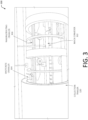
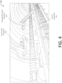
- FIG. 3 and FIG. 4 depict example systems 300, 400, in which the collection trailer 102 includes a muck conveyor 302 used to move debris away from a workface, and a shotcrete crawler 304 and nailing/bolting crawler 306 engaged with guided structures above the muck conveyor 302.
- the muck conveyor 302 may include a chute, ramp, or other structure for guiding debris away from a workface.
- the muck conveyor 302 may include a conveyor belt or other system for providing motive force to debris.
- the shotcrete crawler 304 and nailing/bolting crawler 306 may perform stabilizing operations within a tunnel or shaft as the collection trailer 120 is advanced within the tunnel or shaft.
- the nailing/bolting crawler 306 may be used for bolting operations, while the shotcrete crawler 304 may be used to provide mortar or other stabilizing materials within the tunnel. While FIG. 3 and FIG. 4 depict the shotcrete crawler 304 and nailing/bolting crawler 306 being associated with an assembly for removal of debris from a workface, in other implementations, the shotcrete crawler 304, nailing/bolting crawler 306, or other tools or assemblies may be associated with the ram accelerator assembly 102, the assembly that includes the reaming tool 108, or separate assemblies or vehicles.
- debris or other materials created by a projectile impact and removed from a shaft or tunnel may be used to form materials for use by the shotcrete crawler 304 to add structural integrity to the saft or tunnel.
- pulverized debris may be used in combination with a binder, such as cement, or one or more additional materials, such as fiberglass, steel, or other structural materials, to provide structural integrity to a section of shaft or tunnel.
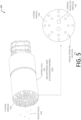
- FIG. 5 is a series of diagrams 500 depicting an implementation of a cutting tool 502 that may be used in conjunction with a ram accelerator assembly 102 to extend a shaft or tunnel using a combination of projectile impacts and boring operations.
- the cutting tool 502 may include a drill bit, such as a rock bit, coring bit, or other type of drill bit having one or more cutting elements that are brought into contact with rock or other material, and that cut or displace the material through rotation of the drill bit.
- the cutting tool 502 is shown having a generally cylindrical body with a cutting surface 504 at an end thereof.
- the cutting surface 504 may include one or more cutting elements that cut, ream, or otherwise displace rock or other material adjacent to the cutting surface 504 as the cutting surface 504 is rotated.
- the cutting surface 504 may also include one or more orifices through which projectiles 202 may be accelerated into contact with a workface adjacent to the cutting surface 504.
- one or more ram accelerator assemblies 102 may be incorporated within the body of the cutting tool 502. The placement of the orifices and ram accelerator assemblies 102 may be used to pre-condition a workface to enable more efficient penetration by the cutting surface 504 and control the shape of the resulting tunnel or shaft.
- the orifices and ram accelerator assemblies 102 may be positioned to cause a central hole to be formed in a first region of geologic material prior to contact with the cutting surface 504.
- the cutting surface 504 may contact the first region of geologic material after the projectile impact, or in some cases, the cutting surface 504 may contact a second region that encloses the first region.
- Compressive forces associated with the cutting surface 504 may interact with a void created by the projectile impact to form tension forces, improving the rate of penetration of the cutting surface 504 through the geologic material, while controlling the breakage of the geologic material.
- a cluster or pattern of holes around a central region of the workface where the cutting surface 504 will extend a tunnel or shaft may be formed in addition to or in place of a central hole.
- other placements of holes may be used. Independent of the location of the holes, each hole may provide one or more free faces that may reflect, redirect, or otherwise interact with shockwaves caused by subsequent projectile impacts or tunneling operations, which may improve the rate at which operations may penetrate through material of a workface and control the shape of a resulting tunnel or shaft.
- FIG. 5 depicts a diagrammatic front view of the cutting surface 504 in which a series of orifices through which accelerated projectiles 202 may pass through the cutting surface 504.
- each orifice may be associated with a ram accelerator assembly 102.
- a single ram accelerator assembly 102 may be configured to accelerate projectiles 202 through multiple orifices.
- a ram accelerator assembly 102 or the cutting surface 504 may be movable to align different orifices with the ram accelerator assembly 102.
- a series of radial projectile orifices 506 are generally evenly spaced about a circumference of the cutting surface 504.
- the cutting surface 504 is shown including an outer ring of eight radial projectile orifices 506 and an inner ring of eight radial projectile orifices 506 positioned inward relative to the outer ring.
- the cutting surface 508 is also shown including two central projectile orifices 508, which in some implementations may have a larger diameter than those of the radial projectile orifices 506.
- projectiles 202 accelerated through the central projectile orifice(s) 508 may have one or more dimensions greater than projectiles 202 accelerated through the radial projectile orifice(s) 506.
- the particular orifices through which projectiles 202 are accelerated may be selected based on the characteristics of the material through which the cutting tool 502 is penetrating, the direction in which a tunnel or shaft is extended, the rate at which it is desired to extend a tunnel, and so forth.
- FIG. 6 is a diagram 600 depicting a system for extending a tunnel 602 using multiple ram accelerator assemblies 102 in combination with the cutting surface 504 of a cutting tool 502.
- the body of the cutting tool 502 is not shown to enable visualization of the position of the cutting surface 504 and ram accelerator assemblies 102.
- FIG. 6 depicts four ram accelerator assemblies 102 arranged in a row.
- the cutting surface 504 may rotate relative to the ram accelerator assemblies 102, and when orifices in the cutting surface 504 are aligned with the ram accelerator assemblies 102, at least a portion of the ram accelerator assemblies 102 may be actuated to accelerate one or more projectiles 202 through the orifices.
- FIG. 6 depicts one or more additional vehicles 604 associated with the cutting tool 502 and ram accelerator assemblies 102.
- the ram accelerator assembly 102 may be advanced through the tunnel 602 using wheels 114, tracks, rails, and so forth, and the vehicles 604 may similarly include wheels 114 or another mechanism for advancement through the tunnel 602.
- the vehicles 604 may be associated with assemblies that support use of the cutting tool 502 or ram accelerator assemblies 102, such as assemblies that provide projectiles 202 and propellant materials into the ram accelerator assemblies 102.
- the vehicles 604 may be associated with assemblies for collecting and removing debris created by interactions between the cutting surface 504 or the projectiles 202 and a workface.
- the specific ram accelerator assemblies 102 that are actuated may be selected based on a desired direction in which to extend the tunnel 602. For example, repeatedly accelerating projectiles 202 toward one side of the cutting surface 504 may cause the tunnel 602 to be extended in an opposing direction due to the force exerted by the acceleration of the projectiles 202 and the interaction between the projectiles 202 and one side of the tunnel 602.
- the specific ram accelerator assemblies 102 that are actuated may be selected based on the characteristics of the material through which the cutting surface 504 is penetrating, a desired rate of penetration, and so forth. For example, a smaller number of ram accelerator assemblies 102, and in some cases zero ram accelerator assemblies 102, may be actuated at times when a sufficient rate of penetration may be achieved using the cutting tool 502.
- FIG. 7 is a series of diagrams 700 depicting example implementations in which different numbers or configurations of ram accelerator assemblies 102 may be used based on the characteristics of a workface, a desired rate of penetration, or a desired shape of a resulting shaft, tunnel, or other type of borehole.
- a large portion of a workface in front of the cutting surface 504 may be affected by projectile impacts by actuating a large number of ram accelerator assemblies 102 associated with the cutting tool 502, as illustrated by a first set of projectile paths 702.
- a large portion of a rock face or other type of workface may be impacted by multiple projectiles 202, which may substantially weaken a large portion of the workface.
- a selected subset of ram accelerator assemblies 102 may be actuated, as illustrated by a second set of projectile paths 704, which may weaken a selected portion of a workface, such as a first portion of geological material that is generally centrally located or enclosed by a second portion of geologic material. Weakening of a selected portion of a workface using projectile impacts may be used to control the rate of penetration through a material, the shape of a tunnel 602 formed in the material, the direction in which a tunnel 602 is extended, and so forth.
- interaction between a cutting surface 504 and a first portion of a workface that has not been weakened by a projectile impact may cause the path of the cutting tool 502 to be diverted way from the first portion of the workface, and toward a second portion of the workface that has been weakened by a projectile impact.
- a portion of a workface such as the percentage of an area of a hole, that is to be weakened by projectiles 202 may be selected, while the remainder of the workface may remain to be removed using drilling or boring operations using a cutting surface 504.
- the portion of the workface that is weakened by projectiles 202 may be selected based on the rate at which a tunnel 602 or shaft may be extended using a cutting tool 502 and the rate at which debris may be removed from a workface.
- a tunnel 602 is extended at a rate that enables debris to accumulate more rapidly than the debris may be removed, use of projectiles 202 to weaken the workface may be limited to conserve materials and slow the rate of penetration through a workface, preventing undesired accumulation of debris.
- projectiles 202 may be accelerated using radial projectile orifices 506 associated with a cutting surface 504, creating a disc-shaped region of a workface that is affected by projectile impacts, while leaving a central portion of the workface unaffected by projectile impacts.
- projectiles 202 may be accelerated using central projectile orifices 508 to selectively form a void in a first region of geologic material that is enclosed by a second region, which may improve the rate of penetration through a workface while enabling debris to fall into a void created in the first region.
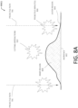
- FIG. 8A is a diagram 800(1) depicting a workface 802 in which an outer region 804 has been affected by one or more projectile impacts 806, as illustrated by projectile paths 706, while an inner region 808 is not affected by projectile impacts 806.
- the inner region 808 may primarily be impacted by the cutting surface 504 of a cutting tool 502, as illustrated by the region of FIG. 8A labeled "cutting interactions" 810.
- a disc-shaped cutting surface 504 having a diameter perpendicular to the workface 802 may be used to remove material from the workface 802.
- projectiles 202 accelerated as illustrated by the projectile paths 706 may break or condition material on both sides of the area where the disc-shaped cutting surface 504 may contact the workfare 802, which may reduce stress on both sides of the disc-shaped cutting surface 504.
- the projectile impacts 806 may form voids that define a perimeter of a region of geologic material. Interaction between compressive forces caused by the cutting interactions 810, or in some cases compressive forces caused by subsequent projectile impacts 806, may interact with the voids at the outer region 804 formed by the initial projectile impacts 806. In such a case, the voids at the outer region 804 may limit breakage or degradation of geologic material outside of the defined perimeter, while also enabling an increased rate of penetration.
- compressive forces that interact with the voids at the outer region 804 may cause tension forces that pull and break rock or other geologic material into the created voids. Interactions between the projectiles 202 and rock or other material may break the material into a desired cross-sectional shape defined in part by the perimeter.
- water jet cutters, drills, mechanical cutters, or other types of tools may be used to pre-condition a surface, such as by forming voids within the outer region 804, in addition to or in place of the projectile impacts 806. Subsequently, projectiles 202 may be accelerated toward the inner region 808 or other cutting tools may be used to perform additional operations.
- water jet cutters, ram accelerator assemblies 102, or other pre-conditioning tools may be controlled remotely, and in some cases may be articulated or aimed in a variety of positions. For example, as described previously, a projectile impact 806 may be used to break or degrade a central region of geologic material in addition to or in place of pre-conditioning a perimeter region of the geologic material.
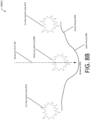
- FIG. 8B is a diagram 800(2) depicting a workface 802 in which an inner region 808 has been affected by one or more projectile impacts 806, as illustrated by projectile paths 706, while an outer region 804 is not affected by projectile impacts 806.
- the inner region 808 may be affected by one or more first projectile impacts 806, and the outer region 804 may be affected by subsequent projectile impacts 806 at a later time.
- projectiles 202 may be directed toward an inner region 808 of geologic material that is enclosed by an outer region 804 to form a central hole in the workface 802 prior to contact between the workface 802 and one or more cutting surfaces 504 or additional projectile impacts 806.
- the central hole created by the initial projectile impact(s) 806 may create a free face that allows shockwaves (e.g., compressive forces) from subsequent operations to be reflected in a manner that enables more effective penetration through geologic material, such as by forming tension forces. Additionally, debris associated with subsequent tunneling operations may fall into a void created by the initial projectile impact(s) 806. In other implementations, other patterns of pre-conditioned holes may create free faces for reflection, redirection, or other interactions with compressive forces resulting from projectile impacts 806 or subsequent tunneling operations.
- shockwaves e.g., compressive forces
- one or more of the systems described with regard to FIGS. 1-8 may be used in conjunction with a mobile (e.g., self-driven or autonomously-controlled) tunneling unit.
- a mobile e.g., self-driven or autonomously-controlled
- Traditional tunnel boring machines include round cutterheads and use rotary torque to carve through rock or other material.
- An excavation process that uses TBMs typically creates a concentric hole, limiting applications into a single cross-section type and ultimately producing a profile with a low utilization ratio of tunneled sections.
- a secondary excavation operation is typically used to provide the desired cross-section.
- Implementations described herein may enable tunnels to be formed and conditioned, such as through trench less excavation operations, and may provide tunnels with cross-sectional shapes that are circular or non-circular, with a significantly higher utilization ratio for tunnel sections than conventional excavation operations.
- the techniques described herein may be used to form a tunnel having varying geometry (e.g., a tunnel that changes in diameter or cross-sectional shape as a function of length). Additionally, use of techniques described herein may enable tunnels to be formed and conditioned with significantly less time and cost when compared to conventional excavation operations.
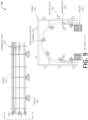
- FIG. 9 is a series of diagrams 900 illustrating an implementation of a tunneling unit 902 that may be used to condition a surface and displace material from the surface using a combination of waterjets 904 or other types of pre-conditioning tools, and ram accelerator assemblies 102.
- the tunneling unit 902 may include a structural frame 906 that is movable forward and backward (e.g., to advance further into and out from a tunnel 602) using tracks 908. In other implementations, wheels, skids, rollers, or other methods for enabling movement of the tunneling unit 902 may be used. In some implementations, movement of the tunneling unit 902 may be controlled remotely.
- the tunneling unit 902 may be configured for automatic movement, such as automatic advancement deeper into a tunnel 602 after use of the tunneling unit 902 to form a segment of the tunnel 602.
- water jets 904 or other pre-conditioning tools may be mounted on the structural frame 906.
- the water jets 904 may include articulating water jet heads (e.g., water jet cutters).
- other types of cutting, reaming, or boring tools may be used to pre-condition a surface in addition to or in place of the water jets 904.
- one or more ram accelerator assemblies 102 may be used in place of or in addition to the water jets 904 to pre-condition a workface 802, such as by forming a central hole in a region of the workface 802 where a tunnel 602 is to be extended.
- holes may be formed, such as the formation of voids that define a perimeter of a region of geologic material. Independent of the placement of the holes, the holes may provide free faces that interact with shockwaves from subsequent projectile impacts 806 or tunneling operations, which may improve the rate at which a tunnel 602 is extended and control the shape of the tunnel 602 that is formed.
- FIG. 9 depicts the structural frame 906 having an outer frame with a generally rectangular shape, upon which the water jets 904 are mounted, and an inner frame having a generally semicircular shape, upon which the ram accelerator assemblies 102 are mounted.
- frames having any shape may be used.
- water jets 904 may be positioned along an outer frame having a semicircular shape, or another desired shape.
- both water jets 904 and ram accelerator assemblies 102 may be positioned along a single frame having a rectangular shape, a semicircular shape, or another shape, and use of separate inner frames and outer frames may be omitted.
- the water jets 904 may be mounted at a leading (e.g., front) edge of the tunneling unit 902, while the ram accelerator assemblies 102 are mounted behind the water jets 904, such as at or near a trailing (e.g., rear) edge of the structural frame 906.
- a rack system may allow each water jet 904 to move independently, articulate, and achieve multiple different positions or orientations to project water toward a surface.
- a water jet 904 or other type of pre-conditioning tool which may include a ram accelerator assembly 102 in some implementations, may be oriented to selectively form a void in selected regions of geologic material, such as a first region enclosed by a second region.
- each water jet 904 may include an actuator, and in some implementations, may be programed to move automatically, independent of other water jets 904.
- a particular water jet 904 may be programmed to run a set task that includes articulating to one or more positions, use of one or more travel rates, feed or flow rates, and other operational parameters.
- a tunneling unit 902 having multiple water jets 904 may be programmed to use the water jets 904, in conjunction with one another, to pre-condition rock or other material for formation of a section of a tunnel 602.
- the tunneling unit 902 may include one or more additional water jets 904, or other pre-conditioning tools, located toward the bottom of the tunneling unit 904 that may be attached to movable arms.
- a water jet 904 or other pre-conditioning tool may be mounted on a six-axis robotic arm, which may allow the water jet 904 to be positioned and oriented in a nearly-infinite number of ways to provide water toward rock or other material.
- other types of arms or movable members including arms with greater or fewer than six axes, may be used.
- these water jets 904 or other pre-conditioning tools may precut a lower portion of a tunnel profile, then be moved out of position as needed for other operations.
- the water jets 904 or other pre-conditioning tools may be used to cut an initial outer profile for a tunnel section. In other implementations, the water jets 904 or other pre-conditioning tools may be used to cut other patterns to pre-condition or weaken a rock face or other material. For example, water jets 904, drills, mechanical cutters, projectile impacts 806, or other mechanisms may be used to pre-condition a workface 802 by forming a central hole at a location where a tunnel 602 is to be extended.
- holes or pre-conditioned regions having other shapes may be formed at other locations, where shockwaves from subsequent projectile impacts 806 or tunneling operations may interact with free faces defined by the holes or other shapes.
- the ram accelerator assemblies 102 after cutting an initial outer profile using water jets 904 or other pre-conditioning tools, and forming a void in a central region of geologic material using a projectile impact 806, the ram accelerator assemblies 102, which in some cases may be articulated, aimed, and so forth, may be used to accelerate projectiles 202 into the geologic material, within the outer profile, to pulverize the material.
- each ram accelerator assembly 102 may be associated with a track 908 or other mechanism to enable movement thereof, and may be moved, pivoted, and articulated to provide projectiles 202 to selected positions in the rock or other material. As the rock or other material is broken by projectile impacts 806, mucking operations, such as those described with regard to FIG. 1 , may be used to transport the material out from the newly-formed tunnel section. The tunneling unit 902 may then be moved forward into the newly-formed tunnel section, and the process may be repeated to extend the tunnel 602. In some implementations, the tunneling unit 902 may be continuously advanced as sections of a tunnel 602 are formed.
- Extension of the tunnel 602 by repeating this process may be used to provide a subsequent tunnel section having the same cross-sectional shape and diameter, or a different (or variable) cross-sectional shape or diameter.
- other types of tunneling operations such as use of cutting tools 502 may be used in place of or in addition to subsequent acceleration of projectiles 202.
- FIG. 10 is a diagram 1000 illustrating a perspective view of the tunneling unit 902 of FIG. 9 positioned to interact with and form a tunnel 602 within a workface 802, such as a rock face or other type of material or surface.
- the tunneling unit 902 may include one or more water jets 904 or other pre-conditioning tools at the leading (e.g., front) end thereof, and ram accelerator assemblies 102 at or near a trailing (e.g., rear) end thereof.
- the water jets 904 may be positioned on an outer portion of a structural frame 906 of the tunneling unit 902, which may have a generally rectangular shape, while the ram accelerator assemblies 102 are positioned on an inner portion of the structural frame 906 having a generally semicircular shape.
- the tunneling until 902 may be positioned on tracks 908 or a similar component to enable movement of the tunneling unit 902 into or out from a tunnel 602.
- the water jets 904, or other tools may be used to pre-condition a portion of a rock face or other material having a non-circular profile, such as a square or rectangular cross-sectional shape.
- FIG. 11A depicts a diagram 1100(1) in which a tunnel profile 1102 for a tunnel 602 may be formed using pre-conditioning devices, while a projectile shot pattern 1104 may be used to displace material to form a section of a tunnel 602 based on the tunnel profile 1102.
- ram accelerator assemblies 102 may then be used to fire projectiles 202 into the workface 802 at locations within the pre-conditioned profile. Interactions between the projectiles 202 and the workface 802 or other material may break, pulverize, or otherwise degrade the material, forming a tunnel section having the shape of the pre-conditioned profile. In other cases, interactions between the projectiles 202 and the workface 802 may weaken the material, and subsequent projectile impacts 806, cutting tools 502, and so forth may be used to displace the weakened material.
- Mucking operations may then be used to remove debris from the tunnel 602 to enable advancing of the tunneling unit 902. Due to the generally open interior of the tunneling unit 902, mucking operations, as well as other operations, may be performed without requiring removal of the tunneling unit 902, such as by passing personnel or equipment beneath the structural frame 906 of the tunneling unit 902. While FIG. 11A depicts an example in which a tunnel profile 1102 is pre-conditioned using water jets 904, in other implementations, a workface 802 may be pre-conditioned through other types of interactions.
- ram accelerator assemblies 102 may accelerate projectiles 202 at selected locations on a workface 802, such as to form one or more voids that define a perimeter, that create a central hole, or another pattern of one or more holes.
- the void(s) formed by projectile impacts 806 may define free faces that may interact with shockwaves caused by subsequent projectile impacts 806 or tunneling operations, which may improve the efficiency at which the material of the workface may be displaced and may control the shape of the resulting section of tunnel 602.
- FIG. 11B depicts a diagram 1100(2) in which a tunnel profile 1102 for a tunnel 602 may be formed using projectile impacts 806, while a projectile shot pattern 1104 may be used to form one or more voids within an enclosed region within the tunnel profile 1102 to improve a rate of penetration of tunneling operations.
- the tunnel profile 1102 may be formed using water jets 904 or other types of pre-conditioning tools.
- one or more projectile impacts 806 may be used to form one or more first voids in a first region of geologic material that is enclosed by a second region.
- FIG. 11B depicts a diagram 1100(2) in which a tunnel profile 1102 for a tunnel 602 may be formed using projectile impacts 806, while a projectile shot pattern 1104 may be used to form one or more voids within an enclosed region within the tunnel profile 1102 to improve a rate of penetration of tunneling operations.
- the tunnel profile 1102 may be formed using water jets 904 or other types of pre-conditioning tools.
- FIG. 11B depicts a projectile shot pattern 1104 that includes a group of voids in the approximate center of the tunnel profile 1102, which may be formed by a series of projectile impacts 806. While FIG. 11B depicts the group of voids including five holes of generally equal size, in other implementations, any number of voids may be formed, including a single void or a large number of voids. Additionally, the void(s) that are formed may have any size. Further, in some implementations, the size of the void(s) that are formed within the enclosed region of the tunnel profile 1102 may have a different size than the voids from the projectile impacts 806 used to define the tunnel profile 1102.
- projectiles 202 used to define the tunnel profile 1102 may be smaller than projectiles 202 used to form voids within the enclosed region.
- projectiles 202 used to define the tunnel profile 1102 may be accelerated with a different velocity to affect the energy associated with the resulting projectile impacts 806.
- the projectile shot patten 1104 shown in FIG. 11B also includes a series of voids that define a perimeter of the tunnel profile 1102.
- one or more projectile impacts 806 may be used to weaken, degrade, displace, or otherwise form voids at the approximate outer edge of a desired tunnel shape.
- the tunnel profile 1102 may be defined by a groove, slot, void, or series of voids that may be formed using water jets 904 or other types of pre-conditioning tools in addition to or in place of projectile impacts 806.
- the central voids may improve the rate of penetration of the tunneling operations.
- compressive forces associated with the tunneling operations may interact with the voids to cause tension forces that pull rock or other geologic material, breaking and displacing the geologic material more effectively than use of compressive forces alone.
- at least a portion of the debris associated with the tunneling operations may fall into the first voids, which may control the direction that the debris is directed.
- Compressive forces associated with the tunneling operations may also interact with the voids that define the perimeter of the tunnel profile 1102, causing tension forces that more efficiently break or displace geologic material when compared to use of compressive forces alone.
- the voids that define the perimeter may limit the effect of the compressive forces on regions of geologic material outside of the perimeter, enabling the resulting tunnel 602 to be provided with a shape based on the tunnel profile 1102.
- pre-conditioning or cutting a rock face or other material may be used.
- rock saw blades, rotating cutters, disc cutters, road headers, water jets with added abrasives, thermal spallation, thermal conditioning (e.g., heating and breaking rock), plasma jet cutters, pre-drilling, and so forth may be used in addition to or in place of water jets 904 or projectile impacts 806 to cut or pre-condition a desired profile.
- Pre-conditioning geologic material to define a perimeter of a tunnel 602 may facilitate formation of tunnels 602 having an irregular cross-sectional shape, such as a square or rectangular perimeter shape, or another desired shape.
- breakage caused by projectile impacts 806 may be limited to a pre-cut or pre-conditioned region of rock, thereby controlling the shape of the material that is removed from a workface 802.
- the gain and near-bore rock damage may be controlled by use of pre-conditioning tools to create a gap, or a region of weakened rock or rock having a different density. In some cases, such a gap or region may be located at a central region of a workface 802 rather than at a perimeter of a tunnel section.
- the region of the rock affected by the pre-conditioning tools may simulate a free face reflection zone so that a shock wave caused by a projectile impact 806 changes from a compression wave to a tension wave, which pulls and breaks the pre-conditioned rock along the perimeter or other pattern of pre-conditioned region(s).
- creation of a cut or pre-conditioned region of rock may provide a boundary zone where, when metallic, ceramic, erodible, or explosive-tipped projectiles 202, or other types of projectiles 202, are fired, the projectiles 202 impact rock within the pre-conditioned region, creating a compression wave that is affected by the cut or weakened region of rock as described above.
- shock waves may be created using other mechanisms in addition to or in place of projectile impacts 806, such as through use of dynamite or other explosives.
- Use of the implementations described herein may more efficiently pre-condition a rock face for breakage compared to conventional methods, and more efficiently break the rock face using projectile impacts 806, which may be timed and spaced in a manner that controls the shockwaves of the impacts and creates a region for broken rock or other material to fall.
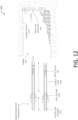
- FIG. 12 is a diagram 1200 illustrating an implementation of interactions between projectiles 202 accelerated using ram accelerator assemblies 102 and a pre-conditioned portion of a tunnel 602.
- a ram accelerator assembly 102 may include a propellant chamber 1202 for providing propellant material to one or more other portions of the ram accelerator assembly 102 to impart a force to a projectile 202.
- the propellant chamber 1202 may include a gas gun or other source of motive force.
- a vent section 1204 may include one or more blast ports or other openings to enable gas created by pressurization, combustion, a chemical reaction, or other interactions with a propellant material to exit the ram accelerator assembly 102.
- Interactions between the propellant material and the projectile 202 may accelerate the projectile 202 through a launch tube 1206 of the ram accelerator assembly 102 into contact with rock or another material, causing a projectile impact 806 to break or weaken the material.
- interactions between the interior of the launch tube 1206 and exterior features of the projectile 202 may impart a ram effect to the projectile 202 to increase the speed thereof.
- the interior of the launch tube 1206 may include baffles, rails, variations in the interior diameter of the launch tube 1206, or other features that interact with the body of the projectile 202 to increase the speed of the projectile 202.
- multiple projectiles 202 or other tunneling operations may be applied to different parts of a pre-conditioned region of a rock face or other geologic material to break the material, as described above, forming debris that may be removed from the resulting tunnel section using mucking operations or other methods of transport or removal.
- a tunnel profile 1102 of the tunnel section may be formed using water jets 904, projectile impacts 806, or other pre-conditioning devices.
- the tunnel section may be extended by breaking the pre-conditioned region within the tunnel profile 1102 using projectile impacts 806 or other tunneling operations, such as use of cutting tools 502.
- the resulting tunnel section may have a cross-sectional shape determined based on the pre-conditioning of the rock or other geologic material.
- a single ram accelerator assembly 102 may be used to accelerate multiple projectiles 202 into a rock face or other material, at the same location or at multiple different locations.
- a single ram accelerator assembly 102 may be used in succession to provide projectiles 202 to various regions of a rock face.
- multiple ram accelerator assemblies 102 may be used, sequentially or simultaneously, to impact the same or different regions of a rock face or other material with projectiles 202.
- the projectile shot patterns 1104 shown in FIGS. 11A and 11B may be applied to a rock face using multiple different ram accelerator assemblies 102 to accelerate projectiles 202 simultaneously or close-in-time.
- Providing a rock face or other workface 802 with a pre-cut region, such as a region having a square shape, may cause plastic strain from a projectile impact 806 to extend into the pre-cut portion of the rock face.
- a pre-conditioned or pre-cut region using water jets 904, rock saws, impacts from projectiles 202, or other methods described above, may be performed as discrete processes, or a continuous process.
- mechanisms for pre-conditioning a workface 802 may be used continuously or in rapid succession between impacts from projectiles 202. While implementations described herein include use of ram accelerator assemblies 102, other mechanisms for accelerating projectiles 202 may be used. For example, supersonic or hypersonic mass drivers, electric rail guns, or other devices may be used to accelerate projectiles 202 toward a workface 802. While FIG. 12 depicts an example in which a perimeter region that defines a tunnel profile 1102 is pre-conditioned prior to impacting a workface 802 with projectiles 202, in other implementations, a pre-conditioned portion of a tunnel 602 may include one or more holes positioned in a central region spaced from a perimeter of the tunnel profile 1102.
- one or more free faces may be defined that may interact with shockwaves caused by subsequent projectile impacts 806 or tunneling operations, which may control the shape of the resulting tunnel section and improve a rate of penetration of the tunneling operations.
- Implementations described herein may be used for formation of tunnels 602 that are horizontal, vertical, angled, or have other orientations.
- a tunnel 602 may also include a mine shaft, a vertical tunnel such as a borehole, or other types of holes or tunnels. Additionally, some implementations may include formation of tunnels 602 under water, or in other pressurized environments. Computing devices and sensors may be used to determine times and orientations for actuating water jets 904 or other pre-conditioning devices, and for actuating ram accelerator assemblies 102 or other methods for accelerating projectiles 202.
- a rock face or other material may be broken first, such as by one or more projectile impacts 806, prior to forming a pre-conditioned region using water jets 904, projectile impacts 806, or other devices, then impacting the rock again to break the rock in a desired shape.
- a pre-conditioned region of a rock face or other material may be not fully removed by projectile impacts 806, such as corner regions of a square-shaped pre-conditioned area.
- a scaling bar, jack hammer, drill bit, cutter, or other mechanical implement may be used to remove the remaining material from the pre-conditioned region.
- a water jet 904 may be used to remove the remaining material, such as by cutting the material in a radial direction.
- additional projectile impacts 806 may be used to remove material not removed by the initial projectile impacts 806.
- a smaller projectile impact 806 e.g., using a smaller projectile 202, less force, or a projectile 202 having different characteristics
- water jets 904 may be articulated to project water in directions that are not parallel with the centerline of the tunnel face, such as to provide better control of the location of the edge of a pre-conditioned region during firing of the water jets 904.
- a system that includes a projectile accelerating device, pumps, power, robotics, pre-conditioning devices, and so forth may include multiple separate units that may be controlled and coordinated using one or more computing devices.
- sensors and other instrumentation may be used to remotely control and coordinate operations of various devices, manually or autonomously, such as to meet certain sets of parameters for rates of production.
- an acoustic barrier, air barrier, gas barrier, or other type of separation may be provided between one or more pieces of equipment, such as to control dust, noise, and so forth.
- FIG. 13 is a diagram 1300 depicting an implementation of a system that includes multiple tunneling units 902.
- a first tunneling unit 902(1) may include one or more of water jets 904 or ram accelerator assemblies 102, as described with regard to FIGS. 9-12 .
- a second tunneling unit 902(2) may be positioned behind the first tunneling unit 902(1) and may include a cutting surface 504 having a ring-shaped configuration.
- the second tunneling unit 902(2) may include a tunnel boring machine (TBM) with a ring cutter.
- TBM tunnel boring machine
- the first tunneling unit 902(1) may be mounted to a generally cylindrical structural frame 906.
- the second tunneling unit 902(2) may be mounted to a generally cylindrical structural frame 906 having a larger diameter than that of the first tunneling unit 902(1).
- FIG. 13 depicts the first tunneling unit 902(1) having water jets 904 at a front end, ram accelerator assemblies 102 at a back end, and noise-reducing baffles 1302 behind the ram accelerator assemblies 102.
- noise-reducing baffles 1302 may be installed in a terminal bulkhead of the first tunneling unit 902(1).
- Bulkheads and baffles may be used to acoustically isolate the first tunneling unit 902(1), reducing the effect of noise caused by rock breaking and firing of projectiles 202 occurring ahead of the second tunneling unit 902(2).
- the second tunneling unit 902(2) may include a manned section having one or more human operators, and use of bulkheads, baffles, or both bulkheads and baffles may reduce the exposure of human operators to noise from rock breaking and firing of projectiles 202.
- the first tunneling unit 902(1) is shown in front of and spaced apart from the second tunneling unit 902(2), which is shown positioned on a larger cylindrical frame 906.
- the first tunneling unit 902(1) and second tunneling unit 902(2) may be spaced apart by a selected separation distance, such as for controlling noise, debris, and so forth.
- FIG. 13 depicts the cutting surface 504 of the second tunneling unit 902(2) having a ring-shaped configuration
- the second tunneling unit 902(2) may include an articulating cutter, such as a long wall miner or road header, disc cutters along a multiple rotation axis machine, and so forth.
- the second tunneling unit 902(2) may have a variety of shapes that differ from those of traditional TBMs. In other implementations, the first tunneling unit 902(1) may be used to pre-condition one or more regions of geologic material, while the second tunneling unit 902(2) is used to displace material to form a tunnel section.
- a conveyor system 1304 may be incorporated within one or more of the tunneling units 902.
- a conveyor belt may be used to transport broken rock, debris, or other materials out from a tunnel 602, and in some cases, to transport other materials into the tunnel 602.
- a rock crusher 1306 or similar device may be positioned on or in front of the conveyor system 1304 to crush, break, or otherwise degrade or process the broken rock or other debris transported using the conveyor system 1304.
- FIG. 13 shows a rock crusher 1306 positioned in association with a portion of a material handling conveyor system 1304 within the structural frame 906 of the second tunneling unit 902(2).
- a rock crusher 1306 may be positioned within the structural frame 906 of the first tunneling unit 902(1) in addition to or in place of a rock crusher 1306 associated with the second tunneling unit 902(2).
- a projectile impact 806 from the first tunneling unit 902(1) may create sizeable pieces of debris that may be crushed or otherwise processed by a rock crusher 1306 before providing the debris to pass through or into the second tunneling unit 902(2).
- both tunneling units 902 may constitute two independently controlled units that share a similar mucking methodology.
- the tunneling units 902 may be independently controlled, while a single conveyor belt or other material conveying system may be used to move material associated with both tunneling units 902.
- the first tunneling unit 902(1) may be used to break a portion of a rock face, as described previously, forming a section of a tunnel 602.
- the second tunneling unit 902(2) being associated with a ring-shaped frame 906 having a larger diameter than that of the first tunneling unit 902(1), may be used to ream the outer edges of the tunnel section created by the first tunneling unit 902(1).
- the second tunneling unit 902(2) may ream or expand the outer edges of the tunnel section previously created by the first tunneling unit 902(1).
- FIG. 14 is a series of diagrams 1400 showing front views of an implementation of the first tunneling unit 902(1) and second tunneling unit 902(2) of FIG. 13 .
- the first tunneling unit 902(1) may include water jets 904 or other types of pre-conditioning devices, and ram accelerator assemblies 102 or other types of projectile acceleration devices, mounted to a structural frame 906.
- the structural frame 906 has a generally cylindrical shape, however in other implementations, other shapes may be used.
- the water jets 904 or other pre-conditioning tools may be used to pre-cut or pre-condition a rock face, such as by weakening a perimeter of a region of the rock face or forming one or more voids within an enclosed region of the rock face. Then, the ram accelerator assemblies 102 may be used to accelerate one or more projectiles 202 into the rock face. Impact between the projectiles 202 and the rock face may facilitate breakage of the rock.
- the rate of penetration of the projectile impacts 806 may be improved due to the interaction between compressive forces of the projectile impacts 806 with the voids formed by the pre-conditioning tools, which may cause the shock waves caused by projectile impacts 806 to pull and remove rock from the region of the rock face using tension forces. Additionally, in some cases, the pre-conditioned regions of the geologic material may limit the breakage or displacement of material outside of the perimeter. While FIG. 14 depicts the ram accelerator assemblies 102 positioned along an interior surface of a frame 906, in other implementations, the ram accelerator assemblies 102 may be positioned along an outer surface of the frame 906, or along a front edge of the frame 906. Similarly, the water jets 904 or other pre-conditioning tools may be positioned at other locations on the frame 906. Additionally, in some implementations, ram accelerator assemblies 102 may be used as both pre-conditioning tools and to displace geologic material after pre-conditioning a portion of the geologic material, and use of separate pre-conditioning tools may be omitted.
- the first tunneling unit 902(1) may be a self-contained unit that may be used independently of the second tunneling unit 902(2), and may be independently controllable from the second tunneling unit 902(2).
- the depicted water jets 904, ram accelerator assemblies 102, or other pre-conditioning tools may be actuated to pre-condition the rock face in a full, 360-degree profile.
- the ram accelerator assemblies 102 which may be mounted around the circumference of the frame, may be used to break the pre-conditioned rock face by firing multiple projectiles 202 into the rock face in succession.
- other types of cutting tools may be used in addition to or in place of the ram accelerator assemblies 102.
- Projectile impacts 806 or other tunneling operations may break the region of the rock face affected by the pre-conditioning, causing sections of rock to fall within the newly-formed tunnel section, such as within voids created by the initial projectile impacts 806.
- a conveyor system 1304 within the first tunneling unit 902(1) may be used to transport the material to mucking equipment located farther from the rock face.
- the first tunneling unit 902(1) may include a material-handling arm 1402, such as an excavator arm and bucket, which may be mounted to the leading edge of the frame 906 of the first tunneling unit 902(1).
- the material-handling arm 1402 may be remotely, automatically, or manually controllable to facilitate movement of broken rock or other materials away from or toward the rock face. While FIG. 14 depicts an excavator arm and bucket as an example device for conveying debris and other materials, other types of devices for moving material may also be used.
- each water jet 904, ram accelerator assembly 102, the depicted material-handling arm 1402, and the conveyor system 1304 shown in the first tunneling unit 902(1) may be independently and automatically operated, such as remotely using controls outside of the tunnel 602 or in a manned portion of the second tunneling unit 902(2) located behind the first tunneling unit 902(1).
- FIG. 14 depicts a front view of the second tunneling unit 902(2), which in some implementations may include a ring-shaped cutting surface 504 positioned along a generally cylindrical frame.
- the diameter of the ring cutter may be larger than that of the frame 906 of the first tunneling unit 902(1).
- the cutting surface 504 of the second tunneling unit 902(2) may further ream, weaken, degrade, smooth, or widen a section of tunnel 602 after a rock face is initially broken using the first tunneling unit 902(1).
- the second tunneling unit 902(2) may include an articulating cutter, such as a long wall miner or road header, disc cutters along a multiple rotation axis machine, and so forth. Because the first tunneling unit 902(1) is used to break the majority of rock to form a tunnel section, the cutting surface 504 of the second tunneling unit 902(2) may have a variety of shapes that differ from those of traditional TBMs.
- Broken rock or other materials broken by the first tunneling unit 902(1), or by the second tunneling unit 902(2) may pass through a central open section 1404 of the second tunneling unit 902(2).
- the conveyor system 1304 may pass through the open section 1404 and may transport broken rock or other material away from or toward the rock face.
- a rock crusher 1306 or other device for breaking, crushing, or otherwise processing the broken rock or other debris may be associated with the conveyor system 1304.
- the ring-shaped cutting surface 504 of the second tunneling unit 902(2) may act as a reamer that may clean and smooth the diameter of a tunnel section formed by using the first tunneling unit 902(1) to break and remove rock.
- the continuous conveyor system 1304 may be used to transport rock, debris, or other material from either tunneling unit 902 to a rock crusher 1306 located behind the cutting surface 504 of the second tunneling unit 902(2).
- the rock crusher 1306 may process larger rock removed from the rock face by one or both tunneling units 902.
- material processed by the rock crusher 1306 may then be fed to an additional conveyor system 1304 located behind the rock crusher 1306 and transported toward a mucking system.
- one or more ram accelerator assemblies 102 or waterjets 904 may be incorporated within the frame 906 of the second tunneling unit 902(2).
- ram accelerator assemblies 102 may be used to fire projectiles 202 through a hole or lattice pattern within the ring shape of the second tunneling unit 902(2).
- a tunneling unit 902 may be used in combination with a pressurized exhaust system, such as a system that includes one or more pressurized screw augers.
- a pressurized screw auger or another similar device may be used to transfer broken rock created by projectile impacts 806 through a pressure-acoustic barrier within which the tunneling unit 902 may operate. This may enable the tunneling unit to be operated at different pressures, as well as control the passage of exhaust gasses separately, transmit or direct the flow of exhaust gasses, and so forth.
- Some implementations within the present disclosure may include methods for extending a tunnel 602, shaft, or other structure by pre-conditioning a selected region of a workface 802 prior to performing a tunneling operation to remove material from the workface 802 and extend a tunnel 602.
- pre-conditioning a workface 802 may include accelerating one or more projectiles 202 into contact with the workface 802 to form one or more holes at or near a center of a region of the workface 802 where a tunneling operation will be performed to remove material from the workface 802.
- other patterns of holes or other types of pre-conditioned regions may be formed in a workface 802.
- a subsequent operation to displace material from the workface 802 and extend a tunnel 602 may include accelerating one or more projectiles 202 into the workface 802, such as to break rock or other materials.
- a subsequent operation to displace material from the workface 802 and extend a tunnel 602 may include use of a drill or boring tool.
- Pre-conditioning of the workface 802, such as through use of one or more projectile impacts 806, may weaken the material of the workface 802, increasing the rate at which material may be displaced from the workface 802 and a tunnel 602 may be advanced. Additionally, pre-conditioning of the workface 802 may control the resulting shape of a tunnel 602 that is formed.
- the holes or other pre-conditioned region of a workface 802 may simulate free face reflection zones. Shockwaves caused by subsequent projectile impacts 806 or other tunneling operations may interact with the free faces to increase the compressive pressure applied to rock or other material at the workface 802 and to control the shape of the material that is removed from the workface 802. For example, a shockwave caused by a projectile impact 806 may change from a compression wave to a tension wave when crossing a free face reflection zone, which may cause the shockwave to pull and break a pre-conditioned portion of the workface 802 at the region where the holes or other pre-conditioned pattern were formed.
- tunnels 602 and shafts extended in a generally horizontal direction may be extended in a vertical direction.
- a workface 802 located in an uphole or downhole direction in a shaft may be pre-conditioned by forming one or more holes or other pre-conditioning features in geologic material. Subsequent projectile impacts 806 or use of cutting or boring tools on the workface 802 may then more efficiently penetrate through the geologic material, while the pre-conditioned features of the workface 802 may control the cross-sectional shape of the extended section of the shaft.
- barriers, containers, rock crushers, or other mechanisms may be positioned between the ram accelerator assemblies 102 and the workface 802 to catch ejecta or other debris that may fall toward the ram accelerator assemblies 102 or other equipment.
- the ram accelerator assemblies 102 or other equipment may be engaged with these mechanisms or other structures, which may maintain the ram accelerator assemblies 102 in a selected position relative to the workface 802.
- pre-conditioning of a workface 802 may also be used to control the direction in which ejecta or other debris is generated.
- debris may be generated at the workface 802 where tunneling operations are performed, which may cause removal operations to be required before additional tunneling operations may be performed.
- shockwaves caused by projectile impacts 806 may expel debris in selected directions, facilitated by use of holes, slots, or other features that may be formed in a workface 802 prior to a projectile impact 806 or other tunneling operation.
- FIG. 15 is a diagram 1500 that depicts an example implementation in which a first void 1502, such as a hole, slot, groove, sill, or other type of feature may be formed near the base of a workface 802.
- the first void 1502 may be formed using projectile impacts 806, or in some implementations, one or more preconditioning tools.
- the first void 1502 may be formed using one or more cutting tools 502, or a combination of cutting tools 502 and projectile impacts 806.
- a slot, hole, groove, sill, or other type of void 1502 may be formed by weakening a region of geologic material using one or more projectile impacts 806, then removing material from the region using one or more cutting tools 502.
- FIG. 15 depicts a ram accelerator assembly 102 which may accelerate a projectile 202 as indicated by a projectile path 706 to impact a portion of the workface 802.
- the force of the projectile 202, forces caused by interaction with the void 1502, and gravity may cause debris 1504 to fall toward the void 1502.
- a portion of a collection tool 1506, such as a tray, trailer, conveyor, or other type of container may be positioned at, near, or at least partially within the void 1502 to catch debris 1504 created by a projectile impact 806, which may facilitate movement of the debris 1504 away from the workface 802.
- rock or other material may be removed by subsequent tunneling operations, such as projectile impacts 806.
- a projectile 202 may be accelerated, such as by using a ram accelerator assembly 102, to impact material on a wall of a tunnel 602 with sufficient energy to remove the material from the wall.
- Impact between the projectile 202 and the wall may then redirect the projectile 202 to impact a workface 802 at the end of the tunnel 602, such as to further extend the tunnel 602, form a hole in the end of the tunnel 602 to pre-condition the workface 802 for further tunneling operations, and so forth.
- projectiles 202 may be used to widen or smooth a tunnel 602 by ricocheting the projectiles 202 on a wall of the tunnel 602, which may then cause the projectiles 202 to impact the workface 802 at the end of the tunnel 602, or another wall or surface of the tunnel 602.
- projectiles 202 may first impact a workface 802 at the end of a tunnel 602 or shaft, and impact between the workface 802 and the projectile 202 may redirect the projectile 202 toward a wall of the tunnel 602 or shaft.
- a projectile 202 that is redirected away from the workface 802 at an angle, such as toward a wall or floor of a tunnel 802 may move ejecta or other debris 1504 away from the workface 802.
- a projectile 202 that ricochets from a workface 802 in a downward direction may displace ejecta that has fallen to the floor near the workface 802 during tunneling operations, such as previous projectile impacts 806.
- a projectile 202 that ricochets from a workface 802 toward a wall, floor, or ceiling of a tunnel 602 may impact the wall, floor, or ceiling and remove material therefrom, such as when smoothing or widening a portion of a tunnel 602.
- impact between a projectile 202 and the workface 802 at a selected angle may cause ejecta from the impact to be directed toward a wall, floor, or ceiling of the tunnel 602 in a manner that may erode, smooth, or displace material from the wall, floor, or ceiling.
- FIG. 16 is a diagram 1600 depicting an interaction between forces associated with a projectile impact 806 and one or more voids 1502(1) within a workface 802.
- first time T1 one or more first projectiles 202 may be accelerated into contact with a first region of geologic material within a workface 802. The first region may be enclosed by a second region of the geologic material.
- FIG. 16 depicts a first projectile path 706(1) indicating contact between a projectile 202 and an interior region of the workface 802, which may be enclosed by an exterior region. Interaction between one or more projectiles 202 and the first region of geologic material may form one or more first voids 1502(1).
- a second projectile 202 may be accelerated into contact with the workface 802.
- the second projectile 202 may impact the first region of the geologic material or the second region of the geologic material.
- FIG. 16 depicts a second projectile path 706(2) indicating contact between a projectile 202 and a different region of the workface 802 that is spaced apart from the first void 1502(1).
- Interaction between the second projectile 202 and the workface 802 may form one or more second voids 1502(2) in the geologic material.
- Interaction between the second projectile 202 and the workface 802 may also apply one or more compressive forces 1602 to the geologic material.
- the compressive force(s) 1602 may propagate through the geologic material to interact with the first void 1502(1).
- interaction between the compressive forces 1602 and the first void 1502(1) may cause tension forces 1604, which may pull or break geologic material near the first void 1502(1) more readily than use of compressive forces 1602 alone.
- the tension forces 1604 may cause debris 1504 displaced by the tension force(s) 1604 to fall within the first void 1502(1) or to fall toward one or more other locations away from the workface 802.
- FIG. 16 depicts a second projectile impact creating compressive forces 1602 that interact with the first void 1502(1)
- other tunneling operations such as use of a cutting tool 502 may be used in place of or in addition to the projectile impacts 806 to create compressive forces 1602 that interact with the first void 1502(1).
- FIG. 17 is a diagram 1700 depicting use of acoustic signals 1702 generated by a projectile impact 806 to determine characteristics of geologic material, which may be used to control the firing parameters of a ram accelerator assembly 102.
- a ram accelerator assembly 102 may be used to accelerate one or more projectiles 202 into contact with a workface 802.
- the projectile impact(s) 806 may cause one or more acoustic signals 1702 that propagate through the geologic material of the workface 802.
- An acoustic detector 1704 may receive the acoustic signal(s) 1702 and generate signal data 1706 indicative of characteristics of the acoustic signal(s) 1702.
- One or more computing devices 1708 may receive the signal data 1706 and determine characteristics of the geologic material based on the signal data 1706. For example, determined characteristics may include a hardness, porosity, the presence or absence of particular materials such as hard rock, porous sandstone, metal or other ores, water, hydrocarbons, and so forth.
- the computing device(s) 1708 may determine firing characteristics 1710 and projectile characteristics 1712 based on the determined characteristics of the geologic material.
- firing characteristics 1710 may include times associated with subsequent acceleration of projectiles 202, locations within the geologic material to be contacted with the projectiles 202, the speed at which projectiles 202 are to be accelerated which may be determined based in part on the types and quantities of propellant materials used, and so forth.
- Projectile characteristics 1712 may include a determined shape, material composition, or type of projectile 202. For example, a steel projectile 202 with a tapered body may be used to penetrate through hard rock, while a wider concrete projectile 202 may be used to penetrate through softer or more porous material.
- a subsequent projectile impact 806 may be omitted or delayed. For example, if soft or porous geologic material is determined, a cutting tool 502 may be used to displace this material without use of projectile impacts 806 before a subsequent projectile 202 is accelerated toward the workface 802.
- the firing characteristics 1710 and projectile characteristics 1712 may be provided to a controller 1714 associated with the ram accelerator assembly 102.
- the computing device(s) 1708 may also determine a structural support characteristic.
- the computing device(s) 1708 may control operation of a bolting or shot-creting tool, or other structural support tools, based on data associated with the acoustic signal(s) 1702.
- the ram accelerator assembly 102 may accelerate a subsequent projectile 202 into contact with the workface 802.
- the location and effects of the resulting projectile impact 806 may be affected at least in part by the firing characteristics 1710 and projectile characteristics 1712.
- the subsequent projectile impact 806 may generate additional acoustic signals 1702, which may be used to determine characteristics of additional regions of the geologic material. For example, the process described in FIG. 17 may be repeated based on multiple projectile impacts 806 and the resulting acoustic signals 1702.
- FIGS. 18A-18E are a series of diagrams 1800 depicting an implementation of a method for sequentially removing regions of geologic material to form a section of a tunnel 602 using a combination of projectile impacts 806 and cutting tools 502. While FIGS. 18A-18E depict one example series of sequential removal of zones of geologic material, in other implementations, zones of geologic material may be removed in any order. Additionally, while FIGS. 18A-18E depict a configuration in which a tunnel 602 is formed by removing generally horizontal zones of geologic material, in other implementations, zones may be oriented vertically or may have other orientations.
- a particular region of geologic material includes a vein of ore or other material to be extracted
- the particular region of geologic material may be removed separately from other zones of geologic material, such as to enable extracted ore to be processed separately from debris created by removal of rock or other undesired geologic material.
- a first zone 1802 of geologic material may be removed using one or more of projectile impacts 806 or cutting tools 502.
- a region of geologic material is shown conceptually divided into multiple zones, with a first zone 1802 positioned slightly above a base level, a second zone 1804 above the first zone 1802, a third zone 1806 above the second zone 1804, a fourth zone 1808 below the first zone 1802, and a fifth zone 1810 below the fourth zone 1808.
- the geologic material may include a combination of materials, such as rock, earth, and so forth.
- Removal of the first zone 1082 of geologic material may include accelerating one or more projectiles 202 into contact with the first zone 1802 to form one or more voids 1502, then contacting the geologic material at the first zone 1802 or at one or more other regions using additional projectile impacts 806 or cutting tools 502 to cause tension forces 1604 that break or otherwise displace the geologic material of the first zone 1802.
- a cutting tool 502 may be used to remove any residual material or debris 1504 from the first zone 1802 that is not removed by the initial tunneling operations, such that the first zone 1802 defines a first void 1502(1).
- a debris collection tool 1506 may be positioned in the first void 1502(1) defined by the removal of geologic material from the first zone 1802.
- the collection tool 1506 may include a tray, trough, portion of a conveying system, and so forth that may be used to catch debris 1504 that falls from above the first void 1502(1) during subsequent operations.
- a perimeter region of the second zone 1804 may be pre-conditioned.
- pre-conditioning of the perimeter region of the second zone 1804 may include contacting the second zone 1804 with one or more projectiles 202, which may form a series of voids 1502(2) proximate to the perimeter of the second zone 1804.
- water jets 904, cutting tools 502, drills, and so forth may be used to form voids 1502(2), grooves, slots, or other regions of removed material proximate to the perimeter of the second zone 1804.
- geologic material from the second zone 1804 may be removed using one or more of projectile impacts 806 or cutting tools 502.
- contact between a cutting tool 502 or one or more projectiles 202 and the second zone 1804 of geologic material may cause compressive forces 1602 that interact with the voids 1502(2) formed at the third time T3.
- Interaction between the compressive forces 1602 and the voids 1502(2) may cause tension forces 1604 to break the geologic material of the second zone 1804 while limiting the displacement of geologic material beyond the perimeter of the second zone 1804 defined by the voids 1502(2).
- Debris 1504 formed by operations to remove material from the second zone 1804 may fall toward the collection tool 1506, which may facilitate removal of the debris 1504.
- some residual geologic material may remain, such as at the locations indicated in FIG. 18C as the third zone 1806.
- the third zone 1806 of geologic material may be removed by contouring the second zone 1804 with cutting tools 502.
- portions of geologic material may remain at an upper portion of the second zone 1804.
- a road-header tool or other type of cutting tool may be used to displace the geologic material from the third zone 1806, or otherwise contour, smooth, or form the edges of the section of tunnel 602 defined by the perimeter that was pre-conditioned at the third time T3.
- debris 1504 and the collection tool 1506 may be removed from the region of geologic material, and a perimeter region of the fourth zone 1808 may be pre-conditioned.
- one or more projectile impacts 806, water jets 904, drills, cutting tools 502, or other pre-conditioning tools may be used to form one or more voids 1502(3), grooves, slots, or other regions of removed or displaced geologic material proximate to the perimeter of the fourth zone 1808.
- the fourth zone 1808 of geologic material may be removed using one or more of projectile impacts 806 or cutting tools 502.
- the operations performed to remove the material from the fourth zone 1808 may cause compressive forces 1602 that interact with the voids 1502(3) to cause tension forces 1604 that break geologic material from the fourth zone 1808 more readily than use of compressive forces 1602 alone.
- Some residual geologic material may remain at the edges of the fourth zone 1808, as shown in the fifth zone 1810 of FIG. 18E .
- the fifth zone 1810 of geologic material may be removed by contouring the fourth zone 1808 using cutting tools 502.
- FIG. 19 is a diagram 1900 depicting an implementation of a system for selectively removing regions of geologic material based on the characteristics of the geologic material, such as to extract ore or another desired material separately from waste or debris.
- one or more ram accelerator assemblies 102 and in some cases, cutting tools 502, reaming tools 108, impact tools, or other tools for displacing geologic material, may be used to form a shaft or tunnel 602 within geologic material.
- one or more projectiles 202 may be accelerated into contact with a workface 802, and an interaction between the projectiles 202 and the geologic material may weaken the geologic material and form one or more voids.
- a subsequent projectile impact 806 or use of a cutting tool 502 to contact the region of geologic material may apply a compressive force 1602 to the geologic material, which may interact with a void to form a tension force 1604 that more readily breaks rock or other geologic material than use of compressive forces 1602 alone.
- a particular region of geologic material such as a target zone 1902 may include a desired material, such as a vein of ore.
- removal of the target zone 1902 of geologic material separate from other zones of geologic material, which may constitute waste zones 1904 that contain rock, earth, or other undesired materials, may enable the desired material to be collected separately from the undesired materials.
- the target zone 1902 of the geologic material may be pre-conditioned, such as by defining a perimeter region thereof using projectile impacts 806, or other pre-conditioning tools. Then, one or more projectile impacts 806 may be used to weaken the geologic material in the target zone 1902.
- Subsequent projectile impacts 806 or use of cutting tools 502 may then be used to remove the desired material from the target zone 1902.
- Conveying systems may transport the collected material 1906 to a selected location for processing. Because the target zone 1902 of geologic material is removed separately from the waste zone(s) 1904, the collected material 1906 does not include large amounts of waste material 1908 (e.g., rock or other debris).
- waste material 1908 e.g., rock or other debris.
- one or more waste zones 1904 may be removed using projectile impacts 806 or cutting tools 502, as described previously, and the waste material 1908 may be transported away from the workface 802. In other implementations, one or more waste zones 1904 may be removed prior to removal of the target zone 1902 of geologic material.
- the presence or absence of a desired material may be determined.
- the characteristics of a region of geologic material may be determined using other sensor modalities. For example, spectroscopy, radar, neutron scattering, neutron diffraction, x-ray analysis, and so forth. Separate conveying systems or methods, or directions of conveying the resulting debris, may be used based on the known characteristics of the region of geologic material that is impacted by a projectile 202 or cutting tool 502 to cause a desired material such as ore to be transported away from a workface 802 separately from waste material 1908.
- waste material 1908 such as rock may be replaced in a tunnel 602 or shaft, such as to back-fill a mining shaft after removal of a desired vein of ore.
Landscapes
- Engineering & Computer Science (AREA)
- Mining & Mineral Resources (AREA)
- Life Sciences & Earth Sciences (AREA)
- Geology (AREA)
- General Life Sciences & Earth Sciences (AREA)
- Geochemistry & Mineralogy (AREA)
- Physics & Mathematics (AREA)
- Environmental & Geological Engineering (AREA)
- Fluid Mechanics (AREA)
- Aiming, Guidance, Guns With A Light Source, Armor, Camouflage, And Targets (AREA)
Claims (15)
- Procédé comprenant :
l'accélération d'un ou plusieurs premiers projectiles en contact avec une première région de matériau géologique, dans lequel :le matériau géologique comporte une seconde région qui entoure la première région ; etune première interaction entre le ou les premiers projectiles et la première région affaiblit le matériau géologique au niveau de la première région et forme un premier vide en déplaçant le matériau géologique ;la détermination des données indiquant une propagation d'un signal acoustique (1702) associé à la première interaction à travers le matériau géologique ;la détermination d'une caractéristique d'une ou plusieurs régions parmi la première région ou la seconde région du matériau géologique en fonction des données indiquant la propagation du signal acoustique (1702) ;la détermination d'un ou plusieurs éléments parmi une caractéristique de projectile (1712), une caractéristique de tir (1710) ou un emplacement au sein du matériau géologique en fonction de la caractéristique de la ou des régions parmi la première région ou la seconde région du matériau géologique ; etle fait de provoquer un ou plusieurs éléments parmi :le mouvement d'un outil de coupe (502) pour entrer en contact avec l'emplacement,l'accélération d'un ou de plusieurs deuxièmes projectiles vers l'emplacement à l'aide de la caractéristique de tir (1710), oul'utilisation du ou des deuxièmes projectiles comprenant la caractéristique de projectile (1712) pour entrer en contact avec l'emplacement. - Procédé selon la revendication 1, comprenant en outre :
l'accélération du ou des deuxièmes projectiles en contact avec une ou plusieurs régions parmi la première région ou la seconde région, dans lequel :une deuxième interaction entre le ou les deuxièmes projectiles et la ou les régions parmi la première région ou la seconde région applique une force de compression au matériau géologique ;la force de compression interagit avec le premier vide pour former une première force de tension ;
etla première force de tension déplace au moins une partie du matériau géologique de la première région dans le premier vide. - Procédé selon la revendication 2, comprenant en outre :
avant l'accélération du ou des deuxièmes projectiles, la mise en contact de la seconde région avec un ou plusieurs éléments parmi : au moins un troisième projectile ou un matériau associé à un dispositif de préconditionnement, dans lequel une troisième interaction associée à un ou plusieurs éléments parmi l'au moins un troisième projectile ou le matériau associé au dispositif de préconditionnement forme un ou plusieurs seconds vides qui définissent un périmètre, et dans lequel la force de compression interagit avec le ou les seconds vides pour former une seconde force de tension, et le ou les seconds vides réduisent l'interaction entre la force de compression et le matériau géologique à l'extérieur du périmètre. - Procédé selon la revendication 2, comprenant en outre :
en fonction des données indiquant la propagation du signal acoustique, la détermination d'une caractéristique de la seconde région du matériau géologique, dans lequel la caractéristique de la seconde région indique un ou plusieurs éléments parmi une porosité ou une dureté, et dans lequel le ou les deuxièmes projectiles sont accélérés en réponse à une relation entre le ou les éléments parmi la porosité ou la dureté et une valeur seuil. - Procédé selon l'une quelconque des revendications 1 à 3, comprenant en outre :le positionnement d'une partie d'un premier système d'acheminement à l'intérieur du premier vide, dans lequel les débris de la deuxième interaction entrent en contact avec la partie du premier système d'acheminement ; etle transport d'au moins une partie des débris à l'écart de la première région.
- Procédé selon la revendication 5, comprenant en outre :en fonction des données indiquant la propagation du signal acoustique, la détermination d'un premier matériau au niveau de la première région et d'un second matériau au niveau de la seconde région ;le transport des débris associés à la première interaction à l'aide d'un premier système d'acheminement ;
etle transport des débris associés à une deuxième interaction associée à un ou plusieurs éléments parmi l'outil de coupe ou le ou les deuxièmes projectiles à l'aide d'un second système d'acheminement. - Procédé selon l'une quelconque des revendications 1 à 6, comprenant en outre :avant l'accélération du ou des premiers projectiles, la mise en contact de la ou des régions parmi la première région ou la seconde région avec l'outil de coupe pour déplacer le matériau géologique de la ou des régions parmi la première région ou la seconde région ;la détermination, à l'aide d'un ou plusieurs capteurs, d'une seconde caractéristique de la ou des régions parmi la première région ou la seconde région du matériau géologique en fonction du déplacement du matériau géologique à l'aide de l'outil de coupe ; etle fait de déterminer que la seconde caractéristique correspond à un ou plusieurs critères d'accélération du ou des premiers projectiles en contact avec la première région, dans lequel le ou les premiers projectiles sont accélérés en réponse au fait de déterminer que la seconde caractéristique correspond au ou aux critères.
- Système (100) de formation ou de prolongation d'un tunnel (602) ou d'un puits au sein du matériau géologique, le système (100) comprenant :un tube de lancement (1206) comprenant une extrémité orientée vers une première région de matériau géologique, dans lequel le matériau géologique comporte une seconde région qui entoure la première région ;un premier projectile au sein du tube de lancement (1206) ;un matériau propulseur au sein du tube de lancement (1206), dans lequel le matériau propulseur est conçu pour appliquer une force sur le premier projectile afin d'accélérer le premier projectile en contact avec la première région du matériau géologique, de telle sorte qu'une première interaction entre le premier projectile et la première région affaiblit le matériau géologique au niveau de la première région et forme un premier vide en déplaçant le matériau géologique, et de telle sorte que la première interaction entre le premier projectile et la première région du matériau géologique génère un signal acoustique (1702) ;un détecteur acoustique (1704) configuré pour déterminer des données indiquant le signal acoustique (1702) ;un outil de coupe (502) ayant au moins une surface de coupe (504) qui est mobile pour entrer en contact avec une ou plusieurs régions parmi la première région ou la seconde région afin de déplacer au moins une partie du matériau géologique dans le premier vide ; etun ou plusieurs dispositifs informatiques (1708) configurés pour communiquer avec le détecteur acoustique (1704), dans lequel le ou les dispositifs informatiques (1708) sont configurés pour exécuter des instructions exécutables par ordinateur pour :en fonction des données indiquant le signal acoustique (1702), déterminer une caractéristique de la ou des régions parmi la première région ou la seconde région du matériau géologique ;déterminer un ou plusieurs éléments parmi une caractéristique de projectile (1712), une caractéristique de tir (1710) ou un emplacement du matériau géologique en fonction de la caractéristique de la ou des régions parmi la première région ou la seconde région du matériau géologique ; etprovoquer un ou plusieurs parmi :le mouvement de l'outil de coupe (502) pour entrer en contact avec l'emplacement,l'accélération d'un ou de plusieurs deuxièmes projectiles vers l'emplacement à l'aide de la caractéristique de tir (1710), oul'utilisation du ou des deuxièmes projectiles comprenant la caractéristique de projectile (1712) pour entrer en contact avec l'emplacement.
- Système selon la revendication 8, configuré pour provoquer une deuxième interaction entre l'outil de coupe et la seconde région qui applique une force de compression sur le matériau géologique, de telle sorte que : la force de compression interagit avec le premier vide pour former une première force de tension ; et la première force de tension déplace l'au moins une partie du matériau géologique dans le premier vide.
- Système selon la revendication 9, comprenant en outre :
un premier système d'acheminement pouvant être au moins partiellement positionné au sein du premier vide de telle sorte que des débris déplacés à l'aide de l'outil de coupe entrent en contact avec le premier système d'acheminement, le premier système d'acheminement étant conçu pour transporter au moins une partie des débris à l'écart de la ou des régions parmi la première région ou la seconde région. - Système selon la revendication 8, dans lequel le ou les dispositifs informatiques sont configurés pour exécuter des instructions exécutables par ordinateur pour :après l'accélération du premier projectile en contact avec la première région de la couche de matériaugéologique, provoquer l'accélération du ou des deuxièmes projectiles en contact avec la seconde région du matériau géologique ;de telle sorte que :une deuxième interaction entre le ou les deuxièmes projectiles et la seconde région applique une force de compression sur le matériau géologique ;la force de compression interagit avec le premier vide pour former une première force de tension ; etla première force de tension déplace le matériau géologique dans le premier vide.
- Système selon la revendication 8, comprenant en outre :
un outil de préconditionnement orientable vers la seconde région du matériau géologique, et dans lequel le ou les dispositifs informatiques sont configurés pour exécuter des instructions exécutables par ordinateur pour :provoquer l'accélération du matériau de l'outil de préconditionnement en contact avec la seconde région du matériau géologique pour former un ou plusieurs seconds vides qui définissent un périmètre ;de telle sorte que :une force de compression associée à un ou plusieurs parmi l'outil de coupe ou le ou les deuxièmes projectiles interagit avec le ou les seconds vides pour former une force de tension ;le ou les seconds vides réduisent l'interaction entre la force de compression et le matériau géologique à l'extérieur du périmètre ; etla force de tension déplace le matériau géologique au sein du périmètre. - Système selon la revendication 8, dans lequel la caractéristique de la ou des régions parmi la première région ou la seconde région du matériau géologique comporte un ou plusieurs éléments parmi une porosité ou une dureté, et le ou les dispositifs informatiques sont configurés pour exécuter des instructions exécutables par ordinateur pour :déterminer une relation entre le ou les éléments parmi la porosité ou la dureté et une valeur seuil, dans lequel le ou les éléments parmi le mouvement de l'outil de coupe, l'accélération du ou des deuxièmes projectiles ou l'utilisation du ou des deuxièmesprojectiles sont provoqués en réponse à la relation entre le ou les éléments parmi la porosité ou la dureté et la valeur seuil.
- Système selon la revendication 8, comprenant en outre :un premier système d'acheminement ; etun second système d'acheminement,dans lequel le ou les dispositifs informatiques sont configurés pour exécuter des instructions exécutables par ordinateur pour :en fonction des données indiquant le signal acoustique, déterminer un premier matériau au niveau de la première région et un second matériau au niveau de la seconde région ;actionner le premier système d'acheminement pour transporter les débris associés à la première interaction à l'aide du premier système d'acheminement ; etactionner le second système d'acheminement pour transporter les débris associés à une deuxième interaction associée à un ou plusieurs éléments parmi l'outil de coupe ou le ou les deuxièmes projectiles.
- Système selon la revendication 8, comprenant en outre :un ou plusieurs capteurs configurés pour déterminer une caractéristique de la ou des régions parmi la première région ou la seconde région du matériau géologique en fonction du déplacement du matériau géologique à l'aide de l'outil de coupe,dans lequel le ou les dispositifs informatiques sont configurés pour exécuter des instructions exécutables par ordinateur pour :avant l'accélération du premier projectile, provoquer l'entrée en contact de l'outil de coupe avec la ou les régions parmi la première région ou la seconde région afin de déplacer le matériau géologique ;déterminer, à l'aide du ou des capteurs, une seconde caractéristique de la ou des régions parmi la première région ou la seconde région du matériau géologique en fonction du déplacement du matériau géologique à l'aide de l'outil de coupe ; etdéterminer que la seconde caractéristique correspond à un ou plusieurs critères d'accélération du premier projectile en contact avec la première région, de telle sorte que le premier projectile est accéléré en réponse au fait de déterminer que la seconde caractéristique correspond au ou aux critères.
Applications Claiming Priority (4)
| Application Number | Priority Date | Filing Date | Title |
|---|---|---|---|
| US202063120108P | 2020-12-01 | 2020-12-01 | |
| US17/445,168 US11624235B2 (en) | 2020-08-24 | 2021-08-16 | Ram accelerator augmented drilling system |
| US17/457,007 US11976556B2 (en) | 2020-08-24 | 2021-11-30 | Tunneling and mining method using pre-conditioned hole pattern |
| PCT/US2021/072669 WO2022120347A1 (fr) | 2020-11-12 | 2021-12-01 | Procédé de forage en tunnel et d'exploitation minière à l'aide d'une maille de sondage pré-conditionnée |
Publications (2)
| Publication Number | Publication Date |
|---|---|
| EP4256165A1 EP4256165A1 (fr) | 2023-10-11 |
| EP4256165B1 true EP4256165B1 (fr) | 2025-04-23 |
Family
ID=86852171
Family Applications (1)
| Application Number | Title | Priority Date | Filing Date |
|---|---|---|---|
| EP21841164.3A Active EP4256165B1 (fr) | 2020-12-01 | 2021-12-01 | Procédé de forage en tunnel et d'exploitation minière à l'aide d'une maille de sondage pré-conditionnée |
Country Status (2)
| Country | Link |
|---|---|
| EP (1) | EP4256165B1 (fr) |
| CA (1) | CA3200764A1 (fr) |
Citations (1)
| Publication number | Priority date | Publication date | Assignee | Title |
|---|---|---|---|---|
| US20170130531A1 (en) * | 2015-11-10 | 2017-05-11 | Hypersciences, Inc. | Projectile drilling system |
-
2021
- 2021-12-01 EP EP21841164.3A patent/EP4256165B1/fr active Active
- 2021-12-01 CA CA3200764A patent/CA3200764A1/fr active Pending
Patent Citations (1)
| Publication number | Priority date | Publication date | Assignee | Title |
|---|---|---|---|---|
| US20170130531A1 (en) * | 2015-11-10 | 2017-05-11 | Hypersciences, Inc. | Projectile drilling system |
Also Published As
| Publication number | Publication date |
|---|---|
| EP4256165A1 (fr) | 2023-10-11 |
| CA3200764A1 (fr) | 2022-06-09 |
Similar Documents
| Publication | Publication Date | Title |
|---|---|---|
| EP4058651B1 (fr) | Système de forage augmenté par projectile | |
| US6857706B2 (en) | Mining method for steeply dipping ore bodies | |
| EP2971431B1 (fr) | Système d'accélérateur de bélier | |
| US11976556B2 (en) | Tunneling and mining method using pre-conditioned hole pattern | |
| US10822877B2 (en) | Enhanced endcap ram accelerator system | |
| CA3042017C (fr) | Systeme de forage a projectile | |
| US20130106166A1 (en) | Horizontal Borehole Mining System and Method | |
| EP4256165B1 (fr) | Procédé de forage en tunnel et d'exploitation minière à l'aide d'une maille de sondage pré-conditionnée | |
| Grasso et al. | Construction methods | |
| CN111927450B (zh) | 基于孔阵超前预裂的硬岩矿体开采设备及其开采方法 | |
| WO2022120347A1 (fr) | Procédé de forage en tunnel et d'exploitation minière à l'aide d'une maille de sondage pré-conditionnée | |
| CN116829805A (zh) | 使用预处理孔图案的隧道挖掘和开采方法 | |
| HK40076779A (en) | Projectile augmented boring system | |
| EP3286401B1 (fr) | Système d'accélérateur à effet stato doté de déflecteurs | |
| Meyer | Tunnel Boring in highly fractured ground | |
| ZA200404120B (en) | Mining method for steeply dipping ore bodies. | |
| Schimmel et al. | Use of a Large-diameter Auger in Mining Anthracite Beds |
Legal Events
| Date | Code | Title | Description |
|---|---|---|---|
| STAA | Information on the status of an ep patent application or granted ep patent |
Free format text: STATUS: UNKNOWN |
|
| STAA | Information on the status of an ep patent application or granted ep patent |
Free format text: STATUS: THE INTERNATIONAL PUBLICATION HAS BEEN MADE |
|
| PUAI | Public reference made under article 153(3) epc to a published international application that has entered the european phase |
Free format text: ORIGINAL CODE: 0009012 |
|
| STAA | Information on the status of an ep patent application or granted ep patent |
Free format text: STATUS: REQUEST FOR EXAMINATION WAS MADE |
|
| 17P | Request for examination filed |
Effective date: 20230703 |
|
| AK | Designated contracting states |
Kind code of ref document: A1 Designated state(s): AL AT BE BG CH CY CZ DE DK EE ES FI FR GB GR HR HU IE IS IT LI LT LU LV MC MK MT NL NO PL PT RO RS SE SI SK SM TR |
|
| DAV | Request for validation of the european patent (deleted) | ||
| DAX | Request for extension of the european patent (deleted) | ||
| GRAP | Despatch of communication of intention to grant a patent |
Free format text: ORIGINAL CODE: EPIDOSNIGR1 |
|
| STAA | Information on the status of an ep patent application or granted ep patent |
Free format text: STATUS: GRANT OF PATENT IS INTENDED |
|
| INTG | Intention to grant announced |
Effective date: 20240405 |
|
| RAP3 | Party data changed (applicant data changed or rights of an application transferred) |
Owner name: HYPERSCIENCES, INC. |
|
| GRAS | Grant fee paid |
Free format text: ORIGINAL CODE: EPIDOSNIGR3 |
|
| GRAA | (expected) grant |
Free format text: ORIGINAL CODE: 0009210 |
|
| STAA | Information on the status of an ep patent application or granted ep patent |
Free format text: STATUS: THE PATENT HAS BEEN GRANTED |
|
| AK | Designated contracting states |
Kind code of ref document: B1 Designated state(s): AL AT BE BG CH CY CZ DE DK EE ES FI FR GB GR HR HU IE IS IT LI LT LU LV MC MK MT NL NO PL PT RO RS SE SI SK SM TR |
|
| REG | Reference to a national code |
Ref country code: GB Ref legal event code: FG4D |
|
| REG | Reference to a national code |
Ref country code: CH Ref legal event code: EP |
|
| REG | Reference to a national code |
Ref country code: DE Ref legal event code: R096 Ref document number: 602021029759 Country of ref document: DE |
|
| REG | Reference to a national code |
Ref country code: IE Ref legal event code: FG4D |
|
| P01 | Opt-out of the competence of the unified patent court (upc) registered |
Free format text: CASE NUMBER: APP_19548/2025 Effective date: 20250423 |
|
| REG | Reference to a national code |
Ref country code: SE Ref legal event code: TRGR |
|
| REG | Reference to a national code |
Ref country code: NL Ref legal event code: MP Effective date: 20250423 |
|
| PG25 | Lapsed in a contracting state [announced via postgrant information from national office to epo] |
Ref country code: NL Free format text: LAPSE BECAUSE OF FAILURE TO SUBMIT A TRANSLATION OF THE DESCRIPTION OR TO PAY THE FEE WITHIN THE PRESCRIBED TIME-LIMIT Effective date: 20250423 |
|
| PG25 | Lapsed in a contracting state [announced via postgrant information from national office to epo] |
Ref country code: ES Free format text: LAPSE BECAUSE OF FAILURE TO SUBMIT A TRANSLATION OF THE DESCRIPTION OR TO PAY THE FEE WITHIN THE PRESCRIBED TIME-LIMIT Effective date: 20250423 Ref country code: FI Free format text: LAPSE BECAUSE OF FAILURE TO SUBMIT A TRANSLATION OF THE DESCRIPTION OR TO PAY THE FEE WITHIN THE PRESCRIBED TIME-LIMIT Effective date: 20250423 Ref country code: PT Free format text: LAPSE BECAUSE OF FAILURE TO SUBMIT A TRANSLATION OF THE DESCRIPTION OR TO PAY THE FEE WITHIN THE PRESCRIBED TIME-LIMIT Effective date: 20250825 |
|
| REG | Reference to a national code |
Ref country code: LT Ref legal event code: MG9D |
|
| PG25 | Lapsed in a contracting state [announced via postgrant information from national office to epo] |
Ref country code: GR Free format text: LAPSE BECAUSE OF FAILURE TO SUBMIT A TRANSLATION OF THE DESCRIPTION OR TO PAY THE FEE WITHIN THE PRESCRIBED TIME-LIMIT Effective date: 20250724 |
|
| PG25 | Lapsed in a contracting state [announced via postgrant information from national office to epo] |
Ref country code: PL Free format text: LAPSE BECAUSE OF FAILURE TO SUBMIT A TRANSLATION OF THE DESCRIPTION OR TO PAY THE FEE WITHIN THE PRESCRIBED TIME-LIMIT Effective date: 20250423 |
|
| PG25 | Lapsed in a contracting state [announced via postgrant information from national office to epo] |
Ref country code: BG Free format text: LAPSE BECAUSE OF FAILURE TO SUBMIT A TRANSLATION OF THE DESCRIPTION OR TO PAY THE FEE WITHIN THE PRESCRIBED TIME-LIMIT Effective date: 20250423 |
|
| PG25 | Lapsed in a contracting state [announced via postgrant information from national office to epo] |
Ref country code: HR Free format text: LAPSE BECAUSE OF FAILURE TO SUBMIT A TRANSLATION OF THE DESCRIPTION OR TO PAY THE FEE WITHIN THE PRESCRIBED TIME-LIMIT Effective date: 20250423 |
|
| PG25 | Lapsed in a contracting state [announced via postgrant information from national office to epo] |
Ref country code: RS Free format text: LAPSE BECAUSE OF FAILURE TO SUBMIT A TRANSLATION OF THE DESCRIPTION OR TO PAY THE FEE WITHIN THE PRESCRIBED TIME-LIMIT Effective date: 20250723 |
|
| PG25 | Lapsed in a contracting state [announced via postgrant information from national office to epo] |
Ref country code: IS Free format text: LAPSE BECAUSE OF FAILURE TO SUBMIT A TRANSLATION OF THE DESCRIPTION OR TO PAY THE FEE WITHIN THE PRESCRIBED TIME-LIMIT Effective date: 20250823 |
|
| PG25 | Lapsed in a contracting state [announced via postgrant information from national office to epo] |
Ref country code: LV Free format text: LAPSE BECAUSE OF FAILURE TO SUBMIT A TRANSLATION OF THE DESCRIPTION OR TO PAY THE FEE WITHIN THE PRESCRIBED TIME-LIMIT Effective date: 20250423 |
|
| PG25 | Lapsed in a contracting state [announced via postgrant information from national office to epo] |
Ref country code: DK Free format text: LAPSE BECAUSE OF FAILURE TO SUBMIT A TRANSLATION OF THE DESCRIPTION OR TO PAY THE FEE WITHIN THE PRESCRIBED TIME-LIMIT Effective date: 20250423 Ref country code: SM Free format text: LAPSE BECAUSE OF FAILURE TO SUBMIT A TRANSLATION OF THE DESCRIPTION OR TO PAY THE FEE WITHIN THE PRESCRIBED TIME-LIMIT Effective date: 20250423 |
|
| PGFP | Annual fee paid to national office [announced via postgrant information from national office to epo] |
Ref country code: AT Payment date: 20260113 Year of fee payment: 5 |
|
| PG25 | Lapsed in a contracting state [announced via postgrant information from national office to epo] |
Ref country code: CZ Free format text: LAPSE BECAUSE OF FAILURE TO SUBMIT A TRANSLATION OF THE DESCRIPTION OR TO PAY THE FEE WITHIN THE PRESCRIBED TIME-LIMIT Effective date: 20250423 |
|
| PG25 | Lapsed in a contracting state [announced via postgrant information from national office to epo] |
Ref country code: EE Free format text: LAPSE BECAUSE OF FAILURE TO SUBMIT A TRANSLATION OF THE DESCRIPTION OR TO PAY THE FEE WITHIN THE PRESCRIBED TIME-LIMIT Effective date: 20250423 |
|
| REG | Reference to a national code |
Ref country code: DE Ref legal event code: R097 Ref document number: 602021029759 Country of ref document: DE |
|
| PG25 | Lapsed in a contracting state [announced via postgrant information from national office to epo] |
Ref country code: SK Free format text: LAPSE BECAUSE OF FAILURE TO SUBMIT A TRANSLATION OF THE DESCRIPTION OR TO PAY THE FEE WITHIN THE PRESCRIBED TIME-LIMIT Effective date: 20250423 |
|
| PG25 | Lapsed in a contracting state [announced via postgrant information from national office to epo] |
Ref country code: IT Free format text: LAPSE BECAUSE OF FAILURE TO SUBMIT A TRANSLATION OF THE DESCRIPTION OR TO PAY THE FEE WITHIN THE PRESCRIBED TIME-LIMIT Effective date: 20250423 |
|
| PLBE | No opposition filed within time limit |
Free format text: ORIGINAL CODE: 0009261 |
|
| STAA | Information on the status of an ep patent application or granted ep patent |
Free format text: STATUS: NO OPPOSITION FILED WITHIN TIME LIMIT |
|
| REG | Reference to a national code |
Ref country code: CH Ref legal event code: L10 Free format text: ST27 STATUS EVENT CODE: U-0-0-L10-L00 (AS PROVIDED BY THE NATIONAL OFFICE) Effective date: 20260304 |
|
| PG25 | Lapsed in a contracting state [announced via postgrant information from national office to epo] |
Ref country code: RO Free format text: LAPSE BECAUSE OF FAILURE TO SUBMIT A TRANSLATION OF THE DESCRIPTION OR TO PAY THE FEE WITHIN THE PRESCRIBED TIME-LIMIT Effective date: 20250423 |
|
| 26N | No opposition filed |
Effective date: 20260126 |