EP4256202B1 - Pompe à piston pour dispositif de nettoyage haute pression - Google Patents
Pompe à piston pour dispositif de nettoyage haute pression Download PDFInfo
- Publication number
- EP4256202B1 EP4256202B1 EP21782730.2A EP21782730A EP4256202B1 EP 4256202 B1 EP4256202 B1 EP 4256202B1 EP 21782730 A EP21782730 A EP 21782730A EP 4256202 B1 EP4256202 B1 EP 4256202B1
- Authority
- EP
- European Patent Office
- Prior art keywords
- inlet
- outlet
- valve seat
- inlet valve
- piston pump
- Prior art date
- Legal status (The legal status is an assumption and is not a legal conclusion. Google has not performed a legal analysis and makes no representation as to the accuracy of the status listed.)
- Active
Links
Images





Classifications
-
- F—MECHANICAL ENGINEERING; LIGHTING; HEATING; WEAPONS; BLASTING
- F04—POSITIVE - DISPLACEMENT MACHINES FOR LIQUIDS; PUMPS FOR LIQUIDS OR ELASTIC FLUIDS
- F04B—POSITIVE-DISPLACEMENT MACHINES FOR LIQUIDS; PUMPS
- F04B1/00—Multi-cylinder machines or pumps characterised by number or arrangement of cylinders
- F04B1/04—Multi-cylinder machines or pumps characterised by number or arrangement of cylinders having cylinders in star- or fan-arrangement
- F04B1/0404—Details or component parts
- F04B1/0452—Distribution members, e.g. valves
-
- B—PERFORMING OPERATIONS; TRANSPORTING
- B08—CLEANING
- B08B—CLEANING IN GENERAL; PREVENTION OF FOULING IN GENERAL
- B08B3/00—Cleaning by methods involving the use or presence of liquid or steam
- B08B3/02—Cleaning by the force of jets or sprays
-
- F—MECHANICAL ENGINEERING; LIGHTING; HEATING; WEAPONS; BLASTING
- F04—POSITIVE - DISPLACEMENT MACHINES FOR LIQUIDS; PUMPS FOR LIQUIDS OR ELASTIC FLUIDS
- F04B—POSITIVE-DISPLACEMENT MACHINES FOR LIQUIDS; PUMPS
- F04B1/00—Multi-cylinder machines or pumps characterised by number or arrangement of cylinders
- F04B1/04—Multi-cylinder machines or pumps characterised by number or arrangement of cylinders having cylinders in star- or fan-arrangement
- F04B1/0404—Details or component parts
- F04B1/0421—Cylinders
-
- F—MECHANICAL ENGINEERING; LIGHTING; HEATING; WEAPONS; BLASTING
- F04—POSITIVE - DISPLACEMENT MACHINES FOR LIQUIDS; PUMPS FOR LIQUIDS OR ELASTIC FLUIDS
- F04B—POSITIVE-DISPLACEMENT MACHINES FOR LIQUIDS; PUMPS
- F04B53/00—Component parts, details or accessories not provided for in, or of interest apart from, groups F04B1/00 - F04B23/00 or F04B39/00 - F04B47/00
- F04B53/007—Cylinder heads
-
- F—MECHANICAL ENGINEERING; LIGHTING; HEATING; WEAPONS; BLASTING
- F04—POSITIVE - DISPLACEMENT MACHINES FOR LIQUIDS; PUMPS FOR LIQUIDS OR ELASTIC FLUIDS
- F04B—POSITIVE-DISPLACEMENT MACHINES FOR LIQUIDS; PUMPS
- F04B53/00—Component parts, details or accessories not provided for in, or of interest apart from, groups F04B1/00 - F04B23/00 or F04B39/00 - F04B47/00
- F04B53/16—Casings; Cylinders; Cylinder liners or heads; Fluid connections
- F04B53/162—Adaptations of cylinders
- F04B53/164—Stoffing boxes
-
- F—MECHANICAL ENGINEERING; LIGHTING; HEATING; WEAPONS; BLASTING
- F04—POSITIVE - DISPLACEMENT MACHINES FOR LIQUIDS; PUMPS FOR LIQUIDS OR ELASTIC FLUIDS
- F04B—POSITIVE-DISPLACEMENT MACHINES FOR LIQUIDS; PUMPS
- F04B53/00—Component parts, details or accessories not provided for in, or of interest apart from, groups F04B1/00 - F04B23/00 or F04B39/00 - F04B47/00
- F04B53/22—Arrangements for enabling ready assembly or disassembly
Definitions
- the invention relates to a piston pump for a high-pressure cleaning device for conveying a cleaning liquid with a pump housing which has a first housing part and a second housing part, each of which is designed as a metal part, wherein the first housing part forms a suction line and a pressure line, and wherein the second housing part forms a plurality of pump chambers, into each of which a piston which can be moved back and forth is immersed and which are each in flow connection with the suction line via an inlet channel and with the pressure line via an outlet channel, wherein the inlet channels can each be closed by an inlet valve and the outlet channels can each be closed by an outlet valve, wherein the outlet valves each have a stationary outlet valve seat and an outlet closing body which can be moved back and forth relative to the outlet valve seat and which has an outlet valve plate which can be placed sealingly against the outlet valve seat.
- Such piston pumps are from the DE 10 2009 049 095 A1 known.
- a cleaning liquid such as water
- fed through the suction line can be pressurized and released through the pressure line.
- a pressure hose can be connected to the pressure line, which has a nozzle head at its free end, through which the pressurized cleaning liquid can be directed at an object.
- the piston pump is driven by a drive motor, which is coupled to the pistons of the piston pump, for example, via a wobble plate gear, and drives them to a reciprocating stroke.
- the pump housing has a first and a second housing part, each of which is designed as a metal part.
- the first housing part forms the suction line and the pressure line
- the second housing part forms the pump chambers as well as the inlet and outlet channels, via which the pump chambers are in flow connection with the suction line and the pressure line respectively.
- the inlet channels can each be closed by an inlet valve and the outlet channels can each be closed by an outlet valve.
- Outlet valves are proposed, each of which has an outlet part and an outlet closing body that can be moved back and forth relative to it.
- the outlet part forms an outlet valve seat and the outlet closing body has an outlet valve plate that can be placed against the outlet valve seat in a sealing manner.
- Each outlet part is held in a fixed position in an outlet channel.
- the outlet part is usually made of stainless steel and pressed into an outlet channel or held in a rotationally fixed and axially immovable manner by flanging.
- Piston pumps for high-pressure cleaning devices are known in which the two housing parts of the pump housing are made of a plastic material. This allows the outlet valve seats to be molded directly into a housing part without the need for an additional outlet part.
- pump housings made of a plastic material have a lower pressure resistance than pump housings made of metal parts.
- the object of the present invention is to further develop a piston pump of the type mentioned at the outset in such a way that it can be manufactured more cost-effectively.
- a piston pump of the generic type according to the invention in that the second housing part has a valve receptacle into which all the outlet channels open, and that the piston pump has an outlet valve assembly which forms all the outlet valves, wherein the outlet valve assembly has an outlet part which consists of a plastic material and is inserted into the valve receptacle and which forms all the outlet valve seats.
- the piston pump according to the invention has an outlet valve assembly that forms all the outlet valves.
- the outlet valve assembly comprises an outlet part that is inserted into a valve receptacle.
- the valve receptacle is formed by the second housing part designed as a metal part.
- the outlet part consists of a plastic material and has all the outlet valve seats.
- the outlet valve seats of the piston pump are thus provided by the outlet part. It is therefore not necessary to fix a separate outlet part that forms an outlet valve seat in an outlet channel for each outlet valve.
- Complex post-processing of the second housing part designed as a metal part can also be omitted.
- a single outlet part is used that has all the outlet valve seats of the piston pump according to the invention and is made of a plastic material. This reduces the manufacturing costs of the piston pump and makes it easier to assemble.
- the first housing part and/or the second housing part is preferably designed as a die-cast part or as a formed part.
- the first housing part and/or the second housing part is made of an aluminum or brass material.
- valve receptacle is arranged on the side of the second housing part facing the first housing part.
- the exhaust valve assembly is advantageously designed as a pre-assembled unit. This allows the exhaust valve assembly to be assembled as a self-contained unit before assembly the complete piston pump.
- the exhaust valve assembly can be assembled at a first assembly location and then transported to a second assembly location where the complete piston pump is assembled.
- the outlet part has a plurality of annular outlet valve seat bodies, each of which forms an outlet valve seat.
- the exhaust valve seat is aligned with an exhaust port.
- the second housing part forms a plurality of annular outlet support surfaces in the region of the valve receptacle, which are aligned perpendicularly to a longitudinal axis of the valve receptacle and each adjoin an outlet channel in the direction of flow of the cleaning fluid and against each of which an outlet valve seat body rests with a sealing ring in between.
- the vertical alignment of the outlet support surfaces allows the sealing rings resting on the outlet support surfaces to be designed as axial seals, so that during the manufacture of the second housing part, any grooves that may arise in the region of the valve receptacle and are aligned parallel to the longitudinal axis of the valve receptacle do not impair the sealing effect of the sealing rings.
- Such grooves can arise in particular if the second housing part is designed as a die-cast part, during the manufacture of which demolding takes place. Any grooves that arise in the region of the valve receptacle during demolding extend in the demolding direction, i.e. they extend parallel to the longitudinal axis of the valve receptacle, but not parallel to the outlet support surfaces, since these are aligned perpendicular to the longitudinal axis of the valve receptacle. This means that any grooves that may occur in the area of the valve seat when the second housing part is removed from the mould cannot impair the seal acting in the axial direction.
- the outlet support surfaces each adjoin an outlet channel in the flow direction of the cleaning liquid.
- the outlet valve assembly forms all of the outlet valves of the piston pump. It is advantageous if the outlet valves each have an outlet closing body that can be moved back and forth relative to the outlet part, which has an outlet valve plate that can be placed sealingly against an outlet valve seat and an outlet valve stem that adjoins the outlet valve plate in the direction facing away from the outlet channel. In relation to the flow direction of the cleaning fluid, the outlet valve stem is arranged downstream of the outlet valve seat.
- the outlet valve assembly preferably has a guide body which consists of a plastic material and has a plurality of guide elements, on each of which an outlet valve stem is movably mounted. In such a design, all of the outlet valve stems are guided by means of the guide body. This results in a further simplification of the assembly of the piston pump.
- the guide elements are each designed to guide an outlet valve stem of an outlet closing body.
- the guide elements each form a guide receptacle into which an exhaust valve stem is inserted.
- the guide receptacles each have at least one inner groove extending in the longitudinal direction of the guide receptacle. Cleaning fluid can escape from the respective guide receptacle via the inner groove.
- An exhaust valve spring is advantageously clamped between the guide elements and the exhaust valve plates.
- the exhaust valve spring the exhaust valve disk can be preloaded towards the associated exhaust valve seat.
- the guide body can be detachably and fluid-tightly connected to the outlet part. This makes it particularly easy to design the outlet valve assembly as a pre-assembled unit.
- the outlet valve shafts can each be inserted into a guide receptacle of the guide body, with the outlet valve shafts being surrounded in the area protruding from the guide receptacles by an outlet valve spring, which is supported on the one hand on a guide receptacle and on the other hand on an outlet valve plate.
- the guide body can then be connected to the outlet part in a fluid-tight manner, preferably with a sealing ring in between.
- the outlet part connected to the guide body can be inserted into the valve receptacle of the second housing part.
- the two housing parts of the pump housing can then be joined together.
- the guide body can be plugged into the outlet part with the interposition of one or more sealing rings.
- the guide body can be inserted into the outlet part with the interposition of at least one sealing ring.
- the guide body forms a check valve seat for a central check valve arranged downstream of the outlet valves.
- the outlet part forms the valve seats of the outlet valves and the guide body forms the valve seat of the central check valve. This results in a further simplification of the assembly of the piston pump.
- a check valve closing body can take up a position immediately downstream of the check valve seat formed by the guide body and can be preloaded by a check valve spring towards the check valve seat.
- the central check valve is preferably arranged in the pressure line.
- the first housing part has, on its side facing the second housing part, a housing recess aligned with the valve receptacle of the second housing part, into which the guide body dips with the interposition of at least one sealing ring.
- the outlet valve assembly takes up a position between the first housing part and the second housing part, the first housing part having, on its side facing the second housing part, a housing recess into which the guide body dips, and the second housing part having, on its side facing the first housing part, a valve receptacle aligned with the housing recess, into which the outlet part is inserted.
- the guide body is connected to the first housing part in a liquid-tight manner and the outlet part is connected to the second housing part in a liquid-tight manner and, in addition, the guide body and the outlet part are connected to one another in a liquid-tight manner.
- the at least one sealing ring which is arranged between the guide body and the housing recess of the first housing part, surrounds the guide body in the circumferential direction.
- the guide body has an outwardly projecting annular projection, to which a step of the housing recess directed radially inwards relative to the longitudinal axis of the housing recess is assigned, wherein between the annular projection and a sealing ring is arranged in the step.
- the sealing ring can form an axial seal so that any grooves that may arise in the area of the housing recess during manufacture of the first housing part and are aligned parallel to the longitudinal axis of the housing recess do not impair the sealing effect of the sealing ring.
- Such grooves can arise in particular when the first housing part is designed as a die-cast part during manufacture of which demolding is carried out.
- any grooves that arise in the area of the housing recess during demolding extend in the demolding direction, i.e. they extend parallel to the longitudinal axis of the housing recess, but not parallel to the radially inward-facing step. Any grooves that arise in the area of the housing recess during demolding of the first housing part cannot therefore impair the seal acting in the axial direction.
- the inlet valves each have an inlet part inserted into an inlet channel and an inlet closing body that can be moved back and forth relative to the inlet part, wherein the inlet part has an inlet valve seat and a guide member arranged offset to the inlet valve seat, and wherein the inlet closing body has an inlet valve plate that can be placed sealingly against the inlet valve seat and an inlet valve stem that adjoins the inlet valve plate and is displaceably mounted on the guide member, wherein the inlet part consists of a plastic material and has an annular inlet valve seat body facing the pump chamber, which forms the inlet valve seat, and wherein the guide member is arranged upstream of the inlet valve seat with respect to the flow direction of the cleaning liquid.
- the second housing part forms inlet channels, into each of which an inlet part made of a plastic material is inserted.
- the inlet part has an annular inlet valve seat body that faces the associated pump chamber. and forms the inlet valve seat.
- the inlet part forms a guide member on which the inlet closing body is slidably mounted.
- the inlet part made of plastic makes it possible to provide an inlet valve seat in a cost-effective manner without the need for complex post-processing of the second housing part. Since the inlet part is made of plastic, its manufacturing costs are relatively low.
- the second housing part forms an annular inlet support surface which adjoins the inlet channel in the direction of the pump chamber, which is aligned perpendicular to the longitudinal axis of the inlet channel and against which the inlet valve seat body rests with a contact surface.
- the inlet valve seat body is supported by the inlet support surface of the second housing part.
- the inlet valve seat body has a sealing ring receptacle adjoining the contact surface, in which a sealing ring is arranged that seals the inlet valve seat body against the inlet support surface in the axial direction.
- the sealing ring arranged between the inlet valve seat body and the inlet support surface of the second housing part forms a seal that acts in the axial direction.
- Such grooves can arise in particular when the second housing part is designed as a die-cast part, during the manufacture of which demolding is carried out. Any grooves that arise during demolding extend in the demolding direction, i.e. they extend parallel to the longitudinal axis of the inlet channel, but not parallel to the inlet support surface, since this is aligned perpendicular to the longitudinal axis of the inlet channel. Thus, grooves that arise during demolding of the second housing part cannot impair the seal acting in the axial direction.
- the sealing ring receptacle forms an annular groove surrounding the inlet valve seat body in the circumferential direction with a first groove wall adjoining the contact surface, over which the outer diameter of the inlet valve seat body continuously decreases with increasing distance from the contact surface and to which a second groove wall adjoins.
- the sealing ring holder is preferably designed in the form of a circumferential groove into which a sealing ring can be inserted. This reduces the risk of the sealing ring accidentally coming loose from the sealing ring holder when the inlet part is inserted into the inlet channel.
- the inlet part is held in a rotationally fixed and axially immovable manner relative to the inlet channel.
- the inlet part can be locked to the second housing part.
- the inlet part has at least one holding arm which adjoins the inlet valve seat body in the direction of the suction line and is held in a rotationally fixed manner relative to the inlet channel.
- the inlet part has at least one holding arm upstream of the inlet valve seat body. The inlet part can be easily secured to the inlet channel using the holding arm. The at least one holding arm dips into the inlet channel.
- the at least one holding arm extends through the inlet channel.
- the at least one holding arm engages behind the inlet channel on its side facing the suction line. This ensures that the inlet part, after it has been inserted into the inlet channel from the side facing the associated pump chamber so far that the at least one holding arm engages behind the inlet channel on the side facing away from the pump chamber, can then no longer be easily removed from the inlet channel.
- the at least one holding arm is integrally connected to the inlet valve seat body.
- the at least one first holding arm forms a one-piece plastic molded part together with the inlet valve seat body.
- the inlet part preferably has two holding arms that are diametrically opposed to one another with respect to the longitudinal axis of the inlet channel.
- the two holding arms allow the inlet part to be designed in a mirror-symmetrical and therefore highly resilient manner.
- the inlet closing body has an inlet valve stem which is movably mounted on a guide member of the inlet part. It is advantageous if the guide member is fixed to the at least one holding arm.
- the guide member is integrally connected to the at least one holding arm.
- the guide member together with the at least one holding arm and preferably together with the inlet valve seat body forms a one-piece plastic molded part.
- the at least one holding arm has an end section facing away from the inlet valve seat body, which extends into a recess in the second housing part.
- the end section of the at least one holding arm forms a positive connection with the recess of the second housing part. This makes it easy to fix the inlet part to the second housing part in a rotationally fixed manner.
- the end section of the at least one holding arm is thermally deformable. This allows the at least one holding arm to be easily deformed by thermal exposure after it has been inserted into the inlet channel from the side of the inlet channel facing the associated pump chamber.
- the at least one holding arm can consist of a thermally deformable plastic material.
- the at least one holding arm can, for example, be designed to be straight before being inserted into the inlet channel and can be thermally deformed into a curved or angled shape after being inserted into the inlet channel.
- the end section of the at least one holding arm facing away from the inlet valve seat body is thermally deformed radially outwards after the holding arm has been inserted into the inlet channel, so that the end section is directed outwards with respect to the longitudinal axis of the inlet channel after the thermal deformation and engages behind the inlet channel on the side facing away from the pump chamber.
- the inlet part as a whole is a one-piece plastic molded part.
- the inlet part is made of a POM material (polyoxymethylene material).
- the inlet closing body has an inlet valve plate and an inlet valve stem adjoining the inlet valve plate on the side facing away from the pump chamber.
- the inlet valve plate can be placed sealingly against the inlet valve seat of the inlet part, and the inlet valve stem is slidably mounted on the guide member of the inlet part.
- the inlet valve plate is preferably integrally connected to the inlet valve stem.
- the guide member is preferably ring-shaped.
- the inlet valve stem extends through the guide member and has a stem section protruding from the guide member in the direction of the suction line, to which a spring holder is fixed, with an inlet valve spring being clamped between the spring holder and the guide member.
- the inlet valve spring which is supported on the one hand on the spring holder and on the other hand on the guide member, the inlet valve stem and with it the inlet valve disc can be subjected to a spring force, under the effect of which the inlet valve disc is pressed against the inlet valve seat.
- the inlet valve disc can lift off the inlet valve seat against the effect of the inlet valve spring, so that cleaning fluid can be pumped from the suction line can flow into the pump chamber via the inlet valve. If the piston performs an opposite pressure movement, the inlet valve plate is pressed against the inlet valve seat by the inlet valve spring, so that the cleaning fluid cannot flow back into the suction line via the inlet valve.
- the guide member forms a stop which limits the movement of the inlet valve stem in the direction of the pump chamber and thus also the movement of the inlet valve plate in the direction of the pump chamber.
- FIG. 10 an advantageous embodiment of a piston pump according to the invention for a high-pressure cleaning device is shown schematically and is given the reference number 10.
- a cleaning liquid preferably water
- the piston pump 10 comprises a pump housing 12 with a first housing part 14 and a second housing part 16.
- the two housing parts 14, 16 are each designed as a metal part. In the embodiment shown, they are each designed in the form of an aluminum die-cast part.
- the first housing part 14 defines the front side 18 of the piston pump 10 and forms a suction line 20 and a pressure line 22.
- the second housing part 16 forms three pump chambers, into each of which a piston is immersed.
- All pistons are pushed into the respective pump chamber 24 in an oscillating manner by a wobble plate (not shown in the drawing, but known per se) and are moved by a The coil spring 30 surrounding the respective piston is pushed out of the pump chamber again, so that the volume of the pump chambers 24 changes periodically.
- Each pump chamber 24 is in flow connection with the suction line 20 via an inlet channel 32 of the second housing part 16.
- Each pump chamber 24 is in flow connection with the pressure line 22 via an outlet channel 34 of the second housing part 16.
- the inlet channels 32 are aligned parallel to one another and each have a longitudinal axis 33.
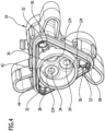
- Two diametrically opposed recesses 36, 38 of the second housing part 16 adjoin the inlet channels 32 on the side facing the suction line 20. This is particularly evident from Figure 4 In the direction of the pump chambers 24, the inlet channels 34 are each adjoined by an annular inlet support surface 40 which is formed by the second housing part 16 and faces the respective pump chamber 24. This is particularly evident from Figure 2 and 5 The inlet support surfaces are aligned perpendicular to the longitudinal axes 33.
- Cleaning fluid to be pressurized can be sucked into the respective pump chamber 24 via the inlet channels 32, and the cleaning fluid can be discharged from the pump chambers 24 via the outlet channels 34.
- the outlet channels 34 open into a central valve receptacle 42 of the second housing part 16, which is circumferentially delimited by a cylinder wall 44.
- the valve receptacle 42 is arranged on the side of the second housing part 16 facing the first housing part 14 and has a longitudinal axis 43 that is aligned parallel to the longitudinal axes 33 of the inlet channels 32.
- the first housing part 14 has on its side facing the second housing part 16 a housing recess 46 which is aligned with the valve receptacle 42 of the second housing part 16 and to which Towards the front side 18 of the first housing part 14, the pressure line 22 is connected.
- a bypass line 48 branches off from the housing recess 46, which is formed by the first housing part 14 and in which a bypass valve 50 is arranged, which is known per se and is therefore only shown schematically in the drawing.
- the bypass line 48 establishes a flow connection between the housing recess 46 and the suction line 20 and can be closed by means of the bypass valve 50.
- the inlet channels 32 can each be closed by an inlet valve 52.
- the inlet valves 52 are identically designed and each have an inlet part 54 which consists of a plastic material, preferably a POM material, and which is inserted into an inlet channel 32.
- the inlet valves 52 each have an inlet closing body 56 which can be moved back and forth in the axial direction relative to the inlet part 54.
- the inlet part 54 has an inlet valve seat body 60, which forms an inlet valve seat 62 of the respective inlet valve 52.
- the inlet valve seat body 60 projects into the respectively assigned pump chamber 24 and is supported with a contact surface 64 facing away from the respective pump chamber 24 on the inlet support surface 40 adjoining the respective inlet channel 32 in the direction of the pump chamber 24.
- the contact surface 64 is followed by a sealing ring receptacle 66 in the form of an annular groove 68 which extends over the circumference of the inlet valve seat body 60 and has a first groove wall 70 directly adjacent to the contact surface 64 and a second groove wall 72 adjacent to this.
- the outer diameter of the inlet valve seat body 60 continuously decreases via the first groove wall 70 with increasing distance from the contact surface 64.
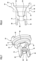
- the outer diameter of the inlet valve seat body 60 continuously increases via the second groove wall 72 with increasing distance from the contact surface 64. This is particularly evident from the Figures 7 and 9 clearly.
- the sealing ring holder 66 receives a first sealing ring 74, which seals the inlet valve seat body 60 relative to the inlet support surface 40 in the axial direction.
- Two holding arms 76, 78 which are diametrically opposed to one another with respect to the longitudinal axis 33 of the inlet channel 32, are connected to the inlet valve seat body 60 of the inlet part 54 in the direction of the suction line 20. These holding arms pass through the inlet channel 34 and each have an end section 80, 82 facing away from the inlet valve seat body 60, which protrudes from the inlet channel 32 on the side of the inlet channel 32 facing away from the pump chamber 24 and, when the inlet valve 52 is mounted, engages behind the respective inlet channel 32 by dipping into a recess 36, 38 of the second housing part 16 and forming a positive connection with it. This will be explained in more detail below.
- the holding arms 76, 78 accommodate an annular guide member 84 between them in the area of the inlet channel 32.
- the outer diameter of the guide member 84 is smaller than the diameter of the inlet channel 32. This allows the cleaning fluid to flow around the guide member 84 within the inlet channel 32.
- the guide member 84 is integrally connected to the holding arms 76, 78, and the holding arms 76, 78 are integrally connected to the inlet valve seat body 60.
- the inlet part 54 forms a one-piece plastic molded part that defines the inlet valve seat body 60, the holding arms 76, 78 and the guide member 84.
- the inlet closing body 56 has an inlet valve plate 88 and an inlet valve stem 90 which is located on the side facing away from the pump chamber 24. Side of the inlet valve plate 88 is integrally connected to the latter. The inlet valve plate 88 can be sealingly placed against the inlet valve seat 62 of the inlet valve seat body 60, and the inlet valve stem 90 extends through the guide member 84 in the direction of the suction line 20.
- a spring holder 94 is fixed to a shaft section 92 of the inlet valve stem 90 that protrudes from the guide member 84 in the direction of the suction line 20.
- An inlet valve spring 96 is clamped between the spring holder 94 and the guide member 84.
- the inlet valve spring 96 is designed as a helical spring that is supported on the one hand on the spring holder 94 and on the other hand on the guide member 84 and surrounds the inlet valve stem 90 in the area between the guide member 84 and the spring holder 94 in the circumferential direction.
- the inlet valve plate 88 which is integrally connected to the inlet valve stem 90, is pressed against the inlet valve seat 62 of the inlet valve seat body 60, so that the inlet valve 52 assumes its closed position.
- the inlet valve 52 opens by the inlet valve plate 88 lifting off the inlet valve seat 62 against the spring force of the inlet valve spring 96 and thereby releasing a flow connection from the suction line 20 to the pump chamber 24 so that cleaning fluid can flow from the suction line 20 into the pump chamber 24 via the inlet channel 32.
- the cleaning fluid can flow around the spring holder 94, the inlet valve spring 96 and the guide member 84 on the outside so that flow losses can be kept to a minimum.
- the inlet valve plate 88 can lift off the inlet valve seat 62 until the spring holder 94 comes to rest on a stop 98 of the guide member 84, which stop is designed in the manner of a projection or a sleeve.
- the stop 98 thus limits the lifting movement of the inlet valve plate 96.
- the inlet valve plate 88 takes its position on the inlet valve seat so that the cleaning fluid cannot flow back into the suction line 20.
- the inlet part 54 can be secured with initially straight-line aligned retaining arms 76, 78, as shown in the Figures 7 and 8 are shown, are inserted into the inlet channel 32 from the side facing the pump chamber 24, so that the contact surface 64 comes to rest on the inlet support surface 40 and the end sections 80, 82 of the holding arms 76, 78 protrude from the inlet channel 32 on the side of the inlet channel 32 facing away from the pump chamber 24.
- the end sections 80, 82 can then be thermally formed, wherein the end sections 80, 82 are pressed radially outwards and dip into the recesses 36, 38 and form a positive connection with them.
- the inlet closing body 56 can then be mounted on the inlet part 54 by inserting the inlet valve stem 90 into the inlet part 54 from the side facing the pump chamber 24, with the inlet valve stem 90 reaching through the guide member 84.
- the inlet valve spring 96 can then be placed on the side facing away from the pump chamber 24 onto the shaft section 92 protruding from the guide member 84, and then the spring holder 94 can be secured to the shaft section 92.
- the spring holder 94 can be secured to the shaft section 92, for example, by means of ultrasonic welding.
- the outlet channels 34 opening into the valve receptacle can each be closed by an outlet valve 99.
- the outlet valves 99 are identically designed and are formed by a pre-assembled outlet valve assembly 100, which is received by the valve receptacle 42 of the second housing part 16 and the housing recess 46 of the first housing part 14.
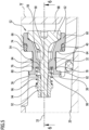
- the exhaust valve assembly 100 is in the Figures 3 and 11 shown enlarged. It comprises an outlet part 102 which consists of a plastic material, for example a POM material.
- the outlet part 102 is inserted into the valve receptacle 52 and has several annular outlet valve seat bodies 104, each of which forms an outlet valve seat 106 of an outlet valve 99.
- the outlet valve assembly 100 has a guide body 108, which is also made of a plastic material, for example a fiber-reinforced plastic material, and which can be detachably and fluid-tightly connected to the outlet part 102.
- the guide body 108 forms guide elements 110 in the form of guide receptacles 112, each of which is aligned with an outlet valve seat 106.
- the outlet part 102 and the guide body 108 accommodate a plurality of outlet closing bodies 114 between them, which can be moved back and forth relative to the outlet part 54 and to the guide body 108 and each have an outlet valve plate 116 and an outlet valve stem 118 of an outlet valve 99 that is integrally connected to it.
- the outlet valve plate 116 can be placed in a sealing manner against an outlet valve seat 106, and the outlet valve stem 118 that is connected to the outlet valve plate 116 on the side of the outlet valve plate 116 facing away from the outlet valve seat 106 dips into a guide receptacle 112 in which it is slidably mounted.
- An exhaust valve spring 120 of an exhaust valve 99 is clamped between the guide receptacles 112 and the exhaust valve plates 116, which spring is supported on the one hand on a guide receptacle 112 and on the other hand on an exhaust valve plate 116 and surrounds an exhaust valve stem 118 in the region between the exhaust valve plate 116 and the guide receptacle 112 in the circumferential direction. This is particularly evident from Figure 11 clearly.
- An inner groove 122 extending in the longitudinal direction of the guide receptacle 112 is formed in the guide receptacle 112, through which cleaning fluid can escape from the guide receptacle 112.
- the second housing part 16 forms annular outlet support surfaces 124, which each adjoin an outlet channel 34 in the direction of the valve receptacle 42 and are aligned perpendicular to the longitudinal axis 43 of the valve receptacle 42.
- the outlet valve seat bodies 114 are each supported on an outlet support surface 124 with their end face 126 facing away from the respective outlet valve seat 106, wherein a second sealing ring 128 is arranged between the end faces 126 and the outlet support surfaces 124, which seals the respective outlet valve seat body 104 relative to the second housing part 16 in the axial direction.
- the guide body 108 is surrounded in the circumferential direction by an annular groove 130 in which a third sealing ring 132 is arranged.
- the third sealing ring 132 ensures the liquid-tight connection between the outlet part 102 and the guide body 108.
- the annular groove 130 is adjoined by an annular projection 134 extending over the outer circumference of the guide body 108.
- the housing recess 46 forms a radially inwardly directed step 136.
- a fourth sealing ring 138 is positioned between the annular projection 134 and the step 136, which seals the guide body 108 in the axial direction relative to the first housing part 14.
- the guide body 108 In its area that extends into the housing recess 46, the guide body 108 forms a check valve seat 140 facing away from the outlet part 102, to which a check closing body 142 can be sealingly applied. In combination with the check closing body 142, the check valve seat 140 forms a central check valve 144.
- the outlet valve assembly 100 is designed as a pre-assembled unit and can be inserted into the valve receptacle 42 and the housing recess 46 when assembling the piston pump 10. Since the outlet valve assembly 100 forms all of the outlet valves 99, this facilitates the assembly of the piston pump 10.
- the two housing parts 14 and 16 are designed as metal parts.
- the provision of the inlet valves 52 and the outlet valves 99 does not require any subsequent processing of the metal parts, since the inlet parts 54 and the outlet part 102 are inserted into the metal parts in the form of plastic components and provide the valve seats.
- the piston pump 10 can therefore be manufactured cost-effectively.
- piston pump 10 is characterized by good suction behavior, since the volume of the pump chambers 24 that cannot be displaced by the pistons 26, 28 of the piston pump 10 can be kept small.
Landscapes
- Engineering & Computer Science (AREA)
- Mechanical Engineering (AREA)
- General Engineering & Computer Science (AREA)
- Details Of Reciprocating Pumps (AREA)
- Valve Housings (AREA)
- Lift Valve (AREA)
- Electrical Discharge Machining, Electrochemical Machining, And Combined Machining (AREA)
- Cleaning By Liquid Or Steam (AREA)
Claims (15)
- Pompe à piston pour un appareil de nettoyage haute pression, permettant de refouler un liquide de nettoyage avec un carter de pompe (12) présentant une première partie de carter (14) et une deuxième partie de carter (16) respectivement conçues sous forme de partie métallique, dans laquelle la première partie de carter (14) forme une conduite d'aspiration (20) et une conduite de pression (22), et dans laquelle la deuxième partie de carter (16) forme plusieurs chambres de pompe (24) dans lesquelles plonge respectivement un piston (26, 28) mobile en va-et-vient et qui sont respectivement en communication fluidique avec la conduite d'aspiration (20) par l'intermédiaire d'un canal d'admission (32) et avec la conduite de pression (22) par l'intermédiaire d'un canal de sortie (34), dans laquelle les canaux d'admission (32) peuvent être fermés respectivement par une soupape d'admission (52) et les canaux de sortie (34) peuvent être fermés respectivement par une soupape de sortie (99), dans laquelle les soupapes de sortie (99) présentent respectivement un siège de soupape de sortie (106) retenu de manière fixe et un corps de fermeture de sortie (114) coulissant en va-et-vient par rapport au siège de soupape de sortie (106) et présentant un disque de soupape de sortie (116) pouvant être appliqué de manière étanche contre un siège de soupape de sortie (106), caractérisée en ce que la deuxième partie de carter (16) présente un logement de soupape (42) dans lequel débouchent les canaux de sortie (34), et en ce que la pompe à piston (10) présente un ensemble formant soupape de sortie (100) qui regroupe l'ensemble des soupapes de sortie (99), dans laquelle l'ensemble formant soupape de sortie (100) présente une partie de sortie (102) qui est en matière plastique et qui est insérée dans le logement de soupape (42) et qui regroupe l'ensemble des sièges de soupape de sortie (106).
- Pompe à piston selon la revendication 1, caractérisée en ce que l'ensemble formant soupape de sortie (100) est conçu sous la forme d'une unité modulaire pouvant être prémontée.
- Pompe à piston selon la revendication 1 ou 2, caractérisée en ce que la partie de sortie (102) présente plusieurs corps de siège de soupape de sortie (104) annulaires formant respectivement un siège de soupape de sortie (106), de manière préférée en ce que la deuxième partie de carter (16) forme dans la région du logement de soupape (42) plusieurs surfaces d'appui de sortie (124) annulaires qui sont orientées perpendiculairement à un axe longitudinal (43) du logement de soupape (42) et se raccordent respectivement à un canal de sortie (34) dans la direction d'écoulement du liquide de nettoyage et sur lesquelles appuie respectivement un corps de siège de soupape de sortie (104) avec interposition d'une bague d'étanchéité (128).
- Pompe à piston selon l'une quelconque des revendications précédentes, caractérisée en ce que les corps de fermeture de sortie (114) présentent respectivement une tige de soupape de sortie (118) se raccordant au disque de soupape de sortie (116) dans la direction opposée au canal de sortie (34).
- Pompe à piston selon la revendication 4, caractérisée en ce que l'ensemble formant soupape de sortie (100) présente un corps de guidage (108) qui est constitué d'une matière plastique et présente plusieurs éléments de guidage (110) sur lesquels respectivement une tige de soupape de sortie (118) est montée de manière à pouvoir coulisser, de manière préférée en ce que les éléments de guidage (110) forment respectivement un logement de guidage (112) dans lequel plonge une tige de soupape de sortie (118), en particulier en ce que les logements de guidage (112) présentent respectivement au moins une rainure intérieure (122) s'étendant dans la direction longitudinale des logements de guidage (112).
- Pompe à piston selon la revendication 5, caractérisée par au moins une des caractéristiques ci-dessous :- un ressort de soupape de sortie (120) est respectivement calé entre les éléments de guidage (110) et le disque de soupape de sortie (116) ;- le corps de guidage (108) peut être relié à la partie de sortie (102) de manière amovible et étanche aux liquides ;- le corps de guidage (108) forme un siège de clapet anti-retour (140) pour un clapet anti-retour (144) central agencé en aval des soupapes de sortie (99) par rapport à la direction d'écoulement du liquide de nettoyage.
- Pompe à piston selon la revendication 5 ou 6, caractérisée en ce que la première partie de carter (14) présente un évidement de carter (46) aligné avec le logement de soupape (42) et dans lequel le corps de guidage (108) plonge avec interposition d'au moins une bague d'étanchéité (132, 138), de manière préférée en ce que la au moins une bague d'étanchéité (132, 138) entoure le corps de guidage (108) dans la direction périphérique et/ou en ce que le corps de guidage (108) présente une saillie annulaire (134) faisant saillie vers l'extérieur et à laquelle est associé un degré (136), orienté radialement vers l'intérieur, de l'évidement de carter (46) de la première partie de carter (14), dans laquelle une bague d'étanchéité (138) est agencée entre la saillie (134) et le degré (136).
- Pompe à piston selon l'une quelconque des revendications précédentes, caractérisée en ce que les soupapes d'admission (52) présentent respectivement une partie d'admission (54) insérée dans un canal d'admission (32) et un corps de fermeture d'admission (56) coulissant en va-et-vient par rapport à la partie d'admission (54), dans laquelle la partie d'admission (54) présente un siège de soupape d'admission (62) et un élément de guidage (84) agencé de manière décalée par rapport au siège de soupape d'admission (62), et dans laquelle le corps de fermeture d'admission (56) présente un disque de soupape d'admission (88) pouvant être appuyé de manière étanche contre le siège de soupape d'admission (62) et une tige de soupape d'admission (90) se raccordant au disque de soupape d'admission (88) et montée de manière à pouvoir coulisser au niveau de l'élément de guidage (84), dans laquelle la partie d'admission (54) est en matière plastique et présente un corps de siège de soupape d'admission (60) annulaire tourné vers la chambre de pompe (24) et formant le siège de soupape d'admission (62), et dans laquelle l'élément de guidage (84) est agencé en amont du siège de soupape d'admission (62) par rapport à la direction d'écoulement du liquide de nettoyage.
- Pompe à piston selon la revendication 8, caractérisée en ce que le corps de siège de soupape d'admission (60) dépasse du canal d'admission (32) en direction de la chambre de pompe (24), de manière préférée en ce que la deuxième partie de carter (16) forme une surface d'appui d'admission (40) annulaire se raccordant au canal d'admission (32) en direction de la chambre de pompe (24) et orientée perpendiculairement à un axe longitudinal (33) du canal d'admission (32) et contre laquelle s'appuie une surface d'appui (64) du corps de siège de soupape d'admission (60), et de manière préférée en ce que le corps de siège de soupape d'admission (60) présente un logement de bague d'étanchéité (66) se raccordant à la surface d'appui (64) et dans lequel est agencée une bague d'étanchéité (74) qui rend le corps de siège de soupape d'admission (60) étanche par rapport à la surface d'appui (64), en particulier en ce que le logement de bague d'étanchéité (66) forme une rainure annulaire (68) entourant le corps de siège de soupape d'admission (60) dans la direction circonférentielle avec une première paroi de rainure (70) qui se raccorde à la surface d'appui (64) et par l'intermédiaire de laquelle le diamètre extérieur du corps de soupape d'admission (60) diminue de manière continue à mesure qu'augmente la distance par rapport à la surface d'appui (64), et à laquelle se raccorde une deuxième paroi d'appui (72) et de manière préférée en ce que le diamètre extérieur du corps de siège de soupape d'admission (60) augmente de manière continue par l'intermédiaire de la deuxième paroi d'appui (72) à mesure qu'augmente la distance par rapport à la surface d'appui (64).
- Pompe à piston selon la revendication 8 ou 9, caractérisée en ce que la partie d'admission (54) présente au moins un bras de retenue (76, 78) qui se raccorde au corps de siège de soupape d'admission (56) en direction de la conduite d'aspiration (20) et qui est retenu de manière solidaire en rotation par rapport au canal d'admission (32).
- Pompe à piston selon la revendication 10, caractérisée par au moins une des caractéristiques ci-dessous :- le au moins un bras de retenue (76, 78) vient en prise derrière le canal d'admission (32) sur son côté tourné vers la conduite d'aspiration (20) ;- le au moins un bras de retenue (76, 78) est relié par complémentarité de matière au corps de siège de soupape d'admission (60) ;- la partie d'admission (54) présente deux bras de retenue (76, 78) diamétralement opposés l'un à l'autre par rapport à un axe longitudinal (33) du canal d'admission (32) ;- l'élément de guidage (84) est fixé au au moins un bras de retenue (76, 78) ;- l'élément de guidage (84) est relié par complémentarité de matière au au moins un bras de retenue (76, 78) .
- Pompe à piston selon la revendication 10 ou 11, caractérisée en ce que le au moins un bras de retenue (76, 78) présente une section d'extrémité (80, 82) qui est opposée au corps de siège de soupape d'admission (60) et qui plonge dans un évidement (36, 38) de la deuxième partie de carter (16), de manière préférée en ce que la section d'extrémité (80, 82) du au moins un bras de retenue (76, 78) forme une liaison par complémentarité de forme avec l'évidement (36, 38) et/ou en ce que la section d'extrémité (80, 82) du au moins un bras de retenue (76, 78) peut être déformée thermiquement.
- Pompe à piston selon l'une quelconque des revendications 8 à 12, caractérisée en ce que la partie d'admission (54) forme une pièce moulée en plastique d'une seule pièce.
- Pompe à piston selon l'une quelconque des revendications 8 à 13, caractérisée en ce que la tige de soupape d'admission (90) traverse l'élément de guidage (84) et présente une section de tige (92) qui dépasse de l'élément de guidage (84) en direction de la conduite d'aspiration (20) et au niveau de laquelle est fixé un support de ressort (94), dans laquelle un ressort de soupape d'admission (96) est calé entre le support de ressort (94) et l'élément de guidage (84).
- Pompe à piston selon la revendication 14, caractérisée en ce que l'organe de guidage (84) forme une butée qui limite le mouvement du disque de soupape d'admission (96) en direction de la chambre de pompe (24).
Applications Claiming Priority (2)
| Application Number | Priority Date | Filing Date | Title |
|---|---|---|---|
| DE102020131798.0A DE102020131798A1 (de) | 2020-12-01 | 2020-12-01 | Kolbenpumpe für ein hochdruckreinigungsgerät |
| PCT/EP2021/076241 WO2022117240A1 (fr) | 2020-12-01 | 2021-09-23 | Pompe à piston pour dispositif de nettoyage haute pression |
Publications (3)
| Publication Number | Publication Date |
|---|---|
| EP4256202A1 EP4256202A1 (fr) | 2023-10-11 |
| EP4256202B1 true EP4256202B1 (fr) | 2024-11-20 |
| EP4256202C0 EP4256202C0 (fr) | 2024-11-20 |
Family
ID=77998992
Family Applications (1)
| Application Number | Title | Priority Date | Filing Date |
|---|---|---|---|
| EP21782730.2A Active EP4256202B1 (fr) | 2020-12-01 | 2021-09-23 | Pompe à piston pour dispositif de nettoyage haute pression |
Country Status (8)
| Country | Link |
|---|---|
| US (1) | US12313047B2 (fr) |
| EP (1) | EP4256202B1 (fr) |
| JP (1) | JP7792406B2 (fr) |
| CN (1) | CN116368297B (fr) |
| AU (1) | AU2021390658B2 (fr) |
| DE (1) | DE102020131798A1 (fr) |
| MX (1) | MX2023006441A (fr) |
| WO (1) | WO2022117240A1 (fr) |
Families Citing this family (2)
| Publication number | Priority date | Publication date | Assignee | Title |
|---|---|---|---|---|
| DE102020131796A1 (de) * | 2020-12-01 | 2022-06-02 | Alfred Kärcher SE & Co. KG | Kolbenpumpe für ein hochdruckreinigungsgerät |
| GB2632277A (en) * | 2023-07-28 | 2025-02-05 | Weir Minerals Netherlands Bv | Valve |
Family Cites Families (33)
| Publication number | Priority date | Publication date | Assignee | Title |
|---|---|---|---|---|
| GB588612A (en) | 1944-08-08 | 1947-05-29 | Norman Ashton Graveson | Improvements in or relating to reciprocating ram pumps |
| FR1344108A (fr) | 1963-01-18 | 1963-11-22 | Compresseur à débit variable | |
| FR1587661A (fr) | 1968-08-02 | 1970-03-27 | ||
| DE6948188U (de) | 1969-12-07 | 1970-04-16 | Appbau Gauting Gmbh | Axialkolben-luftverdichter |
| GB1307866A (en) | 1970-07-04 | 1973-02-21 | Mitchell Co John E | Compressor unit |
| FR2204230A5 (fr) | 1972-10-20 | 1974-05-17 | Dowell Schlumberger | |
| DE2855290A1 (de) | 1978-12-21 | 1980-07-03 | Blau Kg Kraftfahrzeugtech | Anordnung fuer hohlzylindrische ventilstoessel |
| US5299921A (en) | 1992-09-10 | 1994-04-05 | Halliburton Company | Manifold for a front-discharge fluid end reciprocating pump |
| DE4338896C2 (de) | 1993-11-15 | 1997-03-13 | Suttner Gmbh & Co Kg | Axialkolbenpumpe |
| DE19618452B4 (de) | 1996-05-08 | 2005-05-12 | Robert Bosch Gmbh | Aggregat zum Fördern von Kraftstoff aus einem Vorratstank zu einer Brennkraftmaschine |
| DE19801146C1 (de) | 1998-01-14 | 1999-06-24 | Kaercher Gmbh & Co Alfred | Kolbenpumpe für ein Hochdruckreinigungsgerät |
| DE20211512U1 (de) | 2002-06-19 | 2002-11-28 | perma-tec GmbH & Co. KG, 97717 Euerdorf | Rückschlagventil für viskose Medien, insbesondere für Schmierfette |
| US7341435B2 (en) | 2002-06-19 | 2008-03-11 | Gardner Denver, Inc. | Fluid end |
| WO2004074683A1 (fr) | 2003-02-21 | 2004-09-02 | Zexel Valeo Climate Control Corporation | Compresseur volumetrique a pistons |
| DE102005050009B4 (de) | 2005-10-11 | 2007-07-05 | Alfred Kärcher Gmbh & Co. Kg | Hochdruckreinigungsgerät |
| DE102007003521B4 (de) | 2007-01-18 | 2011-06-09 | Alfred Kärcher Gmbh & Co. Kg | Kolbenpumpe für ein Hochdruckreinigungsgerät |
| DE102007047417B4 (de) | 2007-10-04 | 2026-03-05 | Robert Bosch Gmbh | Kolbenpumpe zur Förderung eines Fluids und zugehöriges Bremssystem |
| DE102009006042A1 (de) | 2008-12-19 | 2010-07-01 | Continental Teves Ag & Co. Ohg | Kolbenpumpe, insbesondere zur Versorgung elektrohydraulischer Bremssysteme |
| DE102009049095A1 (de) | 2009-10-01 | 2011-04-07 | Alfred Kärcher Gmbh & Co. Kg | Pumpe für ein Hochdruckreinigungsgerät |
| DE102010013106A1 (de) | 2010-03-26 | 2011-09-29 | Thomas Magnete Gmbh | Pumpe |
| CN102953974B (zh) | 2011-08-31 | 2016-05-25 | 宁波蓝达实业有限公司 | 用于高压清洗机的自吸泵 |
| CN104053907B (zh) * | 2012-01-20 | 2016-09-14 | 阿尔弗雷德·凯驰两合公司 | 用于高压清洁设备的活塞泵 |
| CN104053909B (zh) | 2012-01-20 | 2016-08-17 | 阿尔弗雷德·凯驰两合公司 | 用于高压清洁设备的活塞泵 |
| WO2013123969A1 (fr) | 2012-02-20 | 2013-08-29 | Alfred Kärcher Gmbh & Co. Kg | Pompe pour nettoyeur haute pression et nettoyeur haute pression |
| DE102012015504B4 (de) | 2012-08-03 | 2021-06-24 | Festo Se & Co. Kg | Bauteil mit Einschraubabschnitt und damit ausgestattete Baugruppe |
| WO2015012800A1 (fr) | 2013-07-23 | 2015-01-29 | Halliburton Energy Services, Inc. | Prévention de l'érosion, de la corrosion et de la fatigue de pompes à haute pression |
| DE102013225222A1 (de) | 2013-12-09 | 2015-06-11 | Continental Teves Ag & Co. Ohg | Pumpe |
| DE102014218184A1 (de) | 2014-09-11 | 2016-03-17 | Elringklinger Ag | Ventilvorrichtung |
| DE102014222480A1 (de) | 2014-11-04 | 2016-05-04 | Robert Bosch Gmbh | Kolbenbaugruppe, insbesondere für eine Kolbenpumpe eines Hydraulikaggregats eines Kraftfahrzeugs bzw. Kolbenpumpe |
| EP3237125B1 (fr) | 2014-12-23 | 2022-04-06 | Alfred Kärcher SE & Co. KG | Appareil de nettoyage à haute pression |
| EP3645885B1 (fr) | 2017-06-29 | 2021-06-02 | Alfred Kärcher SE & Co. KG | Appareil de nettoyage à haute pression |
| WO2019169365A1 (fr) | 2018-03-02 | 2019-09-06 | S.P.M. Flow Control, Inc. | Nouvelle vanne ayant une surface d'étanchéité sphérique |
| DE102019200784B4 (de) | 2019-01-23 | 2022-06-30 | Festo Se & Co. Kg | Rückschlagventil |
-
2020
- 2020-12-01 DE DE102020131798.0A patent/DE102020131798A1/de not_active Withdrawn
-
2021
- 2021-09-23 WO PCT/EP2021/076241 patent/WO2022117240A1/fr not_active Ceased
- 2021-09-23 AU AU2021390658A patent/AU2021390658B2/en active Active
- 2021-09-23 JP JP2023527383A patent/JP7792406B2/ja active Active
- 2021-09-23 CN CN202180071735.1A patent/CN116368297B/zh active Active
- 2021-09-23 MX MX2023006441A patent/MX2023006441A/es unknown
- 2021-09-23 EP EP21782730.2A patent/EP4256202B1/fr active Active
-
2023
- 2023-05-31 US US18/326,349 patent/US12313047B2/en active Active
Also Published As
| Publication number | Publication date |
|---|---|
| MX2023006441A (es) | 2023-06-15 |
| CN116368297A (zh) | 2023-06-30 |
| US20230304480A1 (en) | 2023-09-28 |
| AU2021390658A1 (en) | 2023-06-29 |
| JP2023550903A (ja) | 2023-12-06 |
| EP4256202A1 (fr) | 2023-10-11 |
| AU2021390658A9 (en) | 2024-05-02 |
| AU2021390658B2 (en) | 2025-04-24 |
| JP7792406B2 (ja) | 2025-12-25 |
| WO2022117240A1 (fr) | 2022-06-09 |
| CN116368297B (zh) | 2025-09-19 |
| DE102020131798A1 (de) | 2022-06-02 |
| US12313047B2 (en) | 2025-05-27 |
| EP4256202C0 (fr) | 2024-11-20 |
Similar Documents
| Publication | Publication Date | Title |
|---|---|---|
| EP0734494B2 (fr) | Pompe a piston pour l'acheminement d'un fluide hydraulique | |
| EP2805050B1 (fr) | Pompe à piston pour un appareil de nettoyage sous haute pression | |
| WO2007147693A2 (fr) | Pompe à piston | |
| EP3688308B1 (fr) | Vanne de commande de fluide sous pression, notamment destinée à commander un sens de circulation dans un circuit de fluide sous pression et pompe à piston, notamment destinée à refouler un fluide sous pression dans un système de freinage de véhicule à régulation électronique du patinage | |
| EP4256202B1 (fr) | Pompe à piston pour dispositif de nettoyage haute pression | |
| WO2013091931A1 (fr) | Pompe à piston pour système de freinage de véhicule | |
| EP2483560B1 (fr) | Pompe pour appareil de nettoyage haute pression | |
| EP2519743B1 (fr) | Pompe à piston dotée d'une soupape d'admission | |
| WO2013107521A1 (fr) | Pompe à pistons pour appareil de nettoyage à haute pression | |
| EP2483558B1 (fr) | Pompe por une appareil de nettoyage haute pression | |
| DE202015103751U1 (de) | Pumpenvorrichtung | |
| WO2011039114A1 (fr) | Pompe pour nettoyeur haute pression | |
| DE102007020299A1 (de) | Kolbenpumpe für ein Hochdruckreinigungsgerät | |
| EP4256203B1 (fr) | Pompe à piston pour appareil de nettoyage à haute pression | |
| DE202013105650U1 (de) | Kolbenpumpe | |
| DE102009047727A1 (de) | Kolbenpumpe mit einem Schließkörper am Einlassventil | |
| EP2140140A1 (fr) | Pompe à pistons destinée à un nettoyeur haute pression | |
| DE3928375C2 (de) | Kolbenpumpe | |
| EP2805051B1 (fr) | Pompe à pistons pour appareil de nettoyage à haute pression | |
| WO2008086952A1 (fr) | Pompe à piston pour appareil de nettoyage haute pression | |
| DE4426945A1 (de) | Kolbenpumpe | |
| DE4236682A1 (de) | Hydraulische Hochdruckpumpe mit Überströmmanschette | |
| DE102006052776A1 (de) | Kolbenpumpe | |
| WO1998006944A1 (fr) | Appareil de nettoyage haute pression | |
| WO2012110169A1 (fr) | Pompe, en particulier d'un système de freinage de véhicule |
Legal Events
| Date | Code | Title | Description |
|---|---|---|---|
| STAA | Information on the status of an ep patent application or granted ep patent |
Free format text: STATUS: UNKNOWN |
|
| STAA | Information on the status of an ep patent application or granted ep patent |
Free format text: STATUS: THE INTERNATIONAL PUBLICATION HAS BEEN MADE |
|
| PUAI | Public reference made under article 153(3) epc to a published international application that has entered the european phase |
Free format text: ORIGINAL CODE: 0009012 |
|
| STAA | Information on the status of an ep patent application or granted ep patent |
Free format text: STATUS: REQUEST FOR EXAMINATION WAS MADE |
|
| 17P | Request for examination filed |
Effective date: 20230525 |
|
| AK | Designated contracting states |
Kind code of ref document: A1 Designated state(s): AL AT BE BG CH CY CZ DE DK EE ES FI FR GB GR HR HU IE IS IT LI LT LU LV MC MK MT NL NO PL PT RO RS SE SI SK SM TR |
|
| DAV | Request for validation of the european patent (deleted) | ||
| DAX | Request for extension of the european patent (deleted) | ||
| GRAP | Despatch of communication of intention to grant a patent |
Free format text: ORIGINAL CODE: EPIDOSNIGR1 |
|
| STAA | Information on the status of an ep patent application or granted ep patent |
Free format text: STATUS: GRANT OF PATENT IS INTENDED |
|
| INTG | Intention to grant announced |
Effective date: 20240619 |
|
| GRAS | Grant fee paid |
Free format text: ORIGINAL CODE: EPIDOSNIGR3 |
|
| GRAA | (expected) grant |
Free format text: ORIGINAL CODE: 0009210 |
|
| STAA | Information on the status of an ep patent application or granted ep patent |
Free format text: STATUS: THE PATENT HAS BEEN GRANTED |
|
| AK | Designated contracting states |
Kind code of ref document: B1 Designated state(s): AL AT BE BG CH CY CZ DE DK EE ES FI FR GB GR HR HU IE IS IT LI LT LU LV MC MK MT NL NO PL PT RO RS SE SI SK SM TR |
|
| REG | Reference to a national code |
Ref country code: GB Ref legal event code: FG4D Free format text: NOT ENGLISH |
|
| REG | Reference to a national code |
Ref country code: CH Ref legal event code: EP |
|
| REG | Reference to a national code |
Ref country code: DE Ref legal event code: R096 Ref document number: 502021005886 Country of ref document: DE |
|
| REG | Reference to a national code |
Ref country code: IE Ref legal event code: FG4D Free format text: LANGUAGE OF EP DOCUMENT: GERMAN |
|
| P01 | Opt-out of the competence of the unified patent court (upc) registered |
Free format text: CASE NUMBER: APP_61154/2024 Effective date: 20241114 |
|
| U01 | Request for unitary effect filed |
Effective date: 20241212 |
|
| U07 | Unitary effect registered |
Designated state(s): AT BE BG DE DK EE FI FR IT LT LU LV MT NL PT RO SE SI Effective date: 20241223 |
|
| P04 | Withdrawal of opt-out of the competence of the unified patent court (upc) registered |
Free format text: CASE NUMBER: APP_67103/2024 Effective date: 20241218 |
|
| PG25 | Lapsed in a contracting state [announced via postgrant information from national office to epo] |
Ref country code: IS Free format text: LAPSE BECAUSE OF FAILURE TO SUBMIT A TRANSLATION OF THE DESCRIPTION OR TO PAY THE FEE WITHIN THE PRESCRIBED TIME-LIMIT Effective date: 20250320 Ref country code: HR Free format text: LAPSE BECAUSE OF FAILURE TO SUBMIT A TRANSLATION OF THE DESCRIPTION OR TO PAY THE FEE WITHIN THE PRESCRIBED TIME-LIMIT Effective date: 20241120 |
|
| PG25 | Lapsed in a contracting state [announced via postgrant information from national office to epo] |
Ref country code: ES Free format text: LAPSE BECAUSE OF FAILURE TO SUBMIT A TRANSLATION OF THE DESCRIPTION OR TO PAY THE FEE WITHIN THE PRESCRIBED TIME-LIMIT Effective date: 20241120 |
|
| PG25 | Lapsed in a contracting state [announced via postgrant information from national office to epo] |
Ref country code: NO Free format text: LAPSE BECAUSE OF FAILURE TO SUBMIT A TRANSLATION OF THE DESCRIPTION OR TO PAY THE FEE WITHIN THE PRESCRIBED TIME-LIMIT Effective date: 20250220 |
|
| PG25 | Lapsed in a contracting state [announced via postgrant information from national office to epo] |
Ref country code: GR Free format text: LAPSE BECAUSE OF FAILURE TO SUBMIT A TRANSLATION OF THE DESCRIPTION OR TO PAY THE FEE WITHIN THE PRESCRIBED TIME-LIMIT Effective date: 20250221 |
|
| PG25 | Lapsed in a contracting state [announced via postgrant information from national office to epo] |
Ref country code: PL Free format text: LAPSE BECAUSE OF FAILURE TO SUBMIT A TRANSLATION OF THE DESCRIPTION OR TO PAY THE FEE WITHIN THE PRESCRIBED TIME-LIMIT Effective date: 20241120 |
|
| PG25 | Lapsed in a contracting state [announced via postgrant information from national office to epo] |
Ref country code: RS Free format text: LAPSE BECAUSE OF FAILURE TO SUBMIT A TRANSLATION OF THE DESCRIPTION OR TO PAY THE FEE WITHIN THE PRESCRIBED TIME-LIMIT Effective date: 20250220 |
|
| PG25 | Lapsed in a contracting state [announced via postgrant information from national office to epo] |
Ref country code: SM Free format text: LAPSE BECAUSE OF FAILURE TO SUBMIT A TRANSLATION OF THE DESCRIPTION OR TO PAY THE FEE WITHIN THE PRESCRIBED TIME-LIMIT Effective date: 20241120 |
|
| PG25 | Lapsed in a contracting state [announced via postgrant information from national office to epo] |
Ref country code: SK Free format text: LAPSE BECAUSE OF FAILURE TO SUBMIT A TRANSLATION OF THE DESCRIPTION OR TO PAY THE FEE WITHIN THE PRESCRIBED TIME-LIMIT Effective date: 20241120 |
|
| PG25 | Lapsed in a contracting state [announced via postgrant information from national office to epo] |
Ref country code: CZ Free format text: LAPSE BECAUSE OF FAILURE TO SUBMIT A TRANSLATION OF THE DESCRIPTION OR TO PAY THE FEE WITHIN THE PRESCRIBED TIME-LIMIT Effective date: 20241120 |
|
| PLBE | No opposition filed within time limit |
Free format text: ORIGINAL CODE: 0009261 |
|
| STAA | Information on the status of an ep patent application or granted ep patent |
Free format text: STATUS: NO OPPOSITION FILED WITHIN TIME LIMIT |
|
| PGFP | Annual fee paid to national office [announced via postgrant information from national office to epo] |
Ref country code: GB Payment date: 20250703 Year of fee payment: 5 |
|
| 26N | No opposition filed |
Effective date: 20250821 |
|
| U20 | Renewal fee for the european patent with unitary effect paid |
Year of fee payment: 5 Effective date: 20250919 |