EP4256247B1 - Appareil récepteur de rayonnement solaire pour chauffer un milieu de transfert de chaleur dans une centrale héliothermique - Google Patents
Appareil récepteur de rayonnement solaire pour chauffer un milieu de transfert de chaleur dans une centrale héliothermique Download PDFInfo
- Publication number
- EP4256247B1 EP4256247B1 EP21782645.2A EP21782645A EP4256247B1 EP 4256247 B1 EP4256247 B1 EP 4256247B1 EP 21782645 A EP21782645 A EP 21782645A EP 4256247 B1 EP4256247 B1 EP 4256247B1
- Authority
- EP
- European Patent Office
- Prior art keywords
- container
- wall
- transfer medium
- solar
- radiation receiver
- Prior art date
- Legal status (The legal status is an assumption and is not a legal conclusion. Google has not performed a legal analysis and makes no representation as to the accuracy of the status listed.)
- Active
Links
Images


Classifications
-
- F—MECHANICAL ENGINEERING; LIGHTING; HEATING; WEAPONS; BLASTING
- F24—HEATING; RANGES; VENTILATING
- F24S—SOLAR HEAT COLLECTORS; SOLAR HEAT SYSTEMS
- F24S80/00—Details, accessories or component parts of solar heat collectors not provided for in groups F24S10/00-F24S70/00
- F24S80/20—Working fluids specially adapted for solar heat collectors
-
- F—MECHANICAL ENGINEERING; LIGHTING; HEATING; WEAPONS; BLASTING
- F24—HEATING; RANGES; VENTILATING
- F24S—SOLAR HEAT COLLECTORS; SOLAR HEAT SYSTEMS
- F24S20/00—Solar heat collectors specially adapted for particular uses or environments
- F24S20/20—Solar heat collectors for receiving concentrated solar energy, e.g. receivers for solar power plants
-
- F—MECHANICAL ENGINEERING; LIGHTING; HEATING; WEAPONS; BLASTING
- F24—HEATING; RANGES; VENTILATING
- F24S—SOLAR HEAT COLLECTORS; SOLAR HEAT SYSTEMS
- F24S80/00—Details, accessories or component parts of solar heat collectors not provided for in groups F24S10/00-F24S70/00
- F24S80/30—Arrangements for connecting the fluid circuits of solar collectors with each other or with other components, e.g. pipe connections; Fluid distributing means, e.g. headers
-
- F—MECHANICAL ENGINEERING; LIGHTING; HEATING; WEAPONS; BLASTING
- F24—HEATING; RANGES; VENTILATING
- F24S—SOLAR HEAT COLLECTORS; SOLAR HEAT SYSTEMS
- F24S80/00—Details, accessories or component parts of solar heat collectors not provided for in groups F24S10/00-F24S70/00
- F24S2080/03—Arrangements for heat transfer optimization
-
- Y—GENERAL TAGGING OF NEW TECHNOLOGICAL DEVELOPMENTS; GENERAL TAGGING OF CROSS-SECTIONAL TECHNOLOGIES SPANNING OVER SEVERAL SECTIONS OF THE IPC; TECHNICAL SUBJECTS COVERED BY FORMER USPC CROSS-REFERENCE ART COLLECTIONS [XRACs] AND DIGESTS
- Y02—TECHNOLOGIES OR APPLICATIONS FOR MITIGATION OR ADAPTATION AGAINST CLIMATE CHANGE
- Y02E—REDUCTION OF GREENHOUSE GAS [GHG] EMISSIONS, RELATED TO ENERGY GENERATION, TRANSMISSION OR DISTRIBUTION
- Y02E10/00—Energy generation through renewable energy sources
- Y02E10/40—Solar thermal energy, e.g. solar towers
Definitions
- the invention relates to a solar radiation receiver device for heating a heat transfer medium in a solar thermal power plant.
- State-of-the-art solar radiation receiver devices are known as solar particle receivers for solar tower power plants.
- Such receivers use a rotating hollow-cylindrical container in which a closed film of ceramic particles with a diameter of typically 1 mm forms on the inner wall of the rotating cylinder as a heat transfer medium.
- This particle film is heated to over 900°C using concentrated solar radiation and then removed from the cylinder.
- the energy stored in the particles can be temporarily stored in an insulated container and used to generate electricity and/or in process applications.
- the receiver usually consists of three areas.
- a particle distributor is designed as a feed funnel to the rotating cylinder.
- the funnel consists of a cone with welded-on guide plates through which the particles are accelerated and distributed towards the inner wall of the rotating cylinder.
- the particle running surface on the inner wall of the hollow cylinder can be provided with a welded-on grid.
- the grid serves to increase the friction between particles and the inner wall of the cylinder.
- the particles are collected again in a stationary, non-rotating collecting ring as a discharge device at the end of the rotating cylinder and discharged in a controlled manner.
- the collecting ring is sealed against particle loss from the rotating cylinder by means of a metallic axial labyrinth seal.
- the DE 102014106320 A1 describes a device with a solar radiation receiver, which comprises a container that has an outer wall and an interior space surrounded by the outer wall.
- the device comprises a supply device for supplying a heat transfer medium to the interior space of the container.
- the container can be rotated about a rotation axis by means of a rotary drive device of the solar radiation receiver device such that the heat transfer medium is guided along an inner wall of the container to form a heat transfer medium film.
- the device comprises at least one overflow element for forming a rotationally symmetrical inner surface of the heat transfer medium film.
- a device with a solar radiation receiver is known in which particulate heat transfer medium in the container is heated by solar radiation and the particles are removed from the container.
- the object of the invention is to provide a cost-effective solar radiation receiver device with increased efficiency.
- a solar radiation receiver device for heating a heat transfer medium in a solar thermal power plant comprising a container with two opposite ends, which comprises an outer wall and an interior space surrounded by the outer wall; a supply device for supplying the heat transfer medium to the interior space of the container, wherein the supply device is arranged at one of the ends of the container; a discharge device for discharging the heat transfer medium from the container, wherein the discharge device is arranged at the same or opposite end of the container; and an aperture opening for the entry of solar radiation at one of the ends.
- the container has a longitudinal axis which is oriented parallel or at an acute angle of less than 90° to the direction of gravity.
- the container can be rotated about an axis of rotation in a designated direction of rotation by means of a rotary drive device of the solar radiation receiver device in such a way that the heat transfer medium can be guided along an inner wall of the container to form a heat transfer medium film.
- the inner wall of the container has a friction-promoting device.
- the feed device has a front wall with a feed opening and a rear wall directed towards the interior of the container.
- At least one guide element extending at least in the radial direction is arranged between the front wall and the rear wall and is curved along its extension between the feed opening and the outer wall in a direction opposite to the intended direction of rotation.
- the curvature of a curve is understood to mean the change in direction when passing through the curve.
- the guide element changes direction when passing through in a radial direction from radially inside to radially outside, which is opposite to the direction of rotation.
- a more homogeneous distribution of the heat transfer medium which can in particular be designed as a particle stream, can advantageously be achieved at the beginning of the running surface of the heat transfer medium on the inner shell of the container.
- the curved guide elements can be designed in such a way that the residence time of the particles in the area of the rear wall is increased and the contact area with the particles is increased in order to achieve the highest possible heat absorption of the particles or cooling effect of the rear wall.
- the heat transfer medium can advantageously enter the interior of the container evenly and with the lowest possible radial velocity component.
- the relative speed of the individual particles of the heat transfer medium in relation to the guiding components such as the guide elements can be minimized in order to reduce the abrasion of the particles on each other and on the parts of the solar radiation receiver device.
- an overflow option can advantageously be provided on the container, for example a bypass of the guide elements, so that a restriction of the maximum mass flow can be avoided.
- the heat transfer medium can be flowable or pourable.
- the heat transfer medium can be formed by particles.
- the heat transfer medium comprises particles or bits of sintered bauxite or is formed from particles or bits of sintered bauxite.
- the particles or bits can preferably have an average particle diameter of approximately 250 ⁇ m to approximately 1.8 mm.
- powdered media with much smaller grain sizes, such as cement powder can also be used.
- no agglomeration of particles or bits occurs in the heat transfer medium up to at least approximately 800°C, in particular up to at least approximately 1,000°C.
- the particles preferably have a high sphericity.
- the sphericity i.e. the ratio of the surface of a sphere of the same volume to the surface of the particle, can in particular be greater than approximately 0.8, in particular greater than approximately 0.9.
- the particles or bits can preferably be thermal shock resistant.
- the axis of rotation can be parallel or at an acute angle of less than 90°, preferably less than or equal to 80°, to the direction of gravity g.
- the axis of rotation can be coaxial to the longitudinal axis of the container.
- a heat transfer medium film can form particularly favorably on the inner wall of the rotating container, so that the most uniform possible heat transfer to the heat transfer medium can be achieved.
- the at least one guide element can be arranged on the rear wall.
- a height of the at least one guide element can correspond at least partially and/or in sections to a distance between the front wall and the rear wall.
- the residence time of the heat transfer medium in the area of the rear wall can be increased by using curved guide elements. Since the supplied particles of the heat transfer medium have a low temperature, the rear wall, which also represents the rear side of the container opposite the aperture opening and can therefore heat up due to solar radiation and the heated heat transfer medium in the container, can be effectively cooled.
- the curved guide elements can advantageously be designed in such a way that the residence time of the particles in the area of the rear wall is increased and the contact area with the particles is enlarged in order to achieve the highest possible heat absorption of the particles and the cooling effect of the rear wall.
- the guide elements can have a limited height. In this case, the heat transfer medium can flow outwards more quickly via the guide elements at high mass flows.
- the at least one guide element can extend spirally from the feed opening in a radial outward direction.
- the at least one curved guide element can reduce the speed of the heat transfer medium in the radial direction and increase the residence time in the area of the guide element. During this time, the heat transfer medium can absorb heat via the rear wall and the guide element and thus simultaneously cool the rear wall.
- a distribution device can be arranged on an outer edge of the rear wall, which is designed to even out a spatial distribution of the heat transfer medium.
- the distribution device can achieve a uniform distribution of the heat transfer medium on the inner wall of the container, in particular when particles are used as the heat transfer medium, in order to achieve a favorable heat transfer to the heat transfer medium.
- a diameter of the rear wall of the feed device can be smaller than an inner diameter of the container.
- the diameter of the rear wall can be at most 95%, preferably at most 60%, of the inner diameter of the container.
- a favorable value for the diameter of the rear wall depends on the actual design conditions of the solar radiation receiver device and can be adjusted accordingly.
- An inner cone of the feed device designed as a rear wall can thus be designed somewhat shorter than is usual in the prior art.
- the radial position of the particles of the heat transfer medium can be determined, from which point they no longer slide over the rear wall, but are pressed by centrifugal force against the outer cone, i.e. the inside of the front wall of the feed device, from where they are guided into the interior of the container.
- a part of the inner cone can thus be omitted in the area between a corresponding lifting point of the particles and the container wall in order to enable earlier solar irradiation of the particles already in the feed. This can reduce the manufacturing costs of the feed device.
- the heating of the particles can be improved. Consequently, shorter containers can be used.
- the front wall and the rear wall of the feed device can be conical.
- a cone angle can be between 30° and 90°, preferably between 45° and 80°.
- the feed opening can be arranged in a tip of the cone.
- At least the rear wall of the feed device can be designed as a flat surface which is aligned obliquely, preferably perpendicularly, to the longitudinal axis.
- a cone with a conical tip directed towards the feed opening can be arranged in the longitudinal axis for distributing the heat transfer medium.
- the conical design of the feed device which usually has a cone angle of up to 45°, can be advantageously simplified as a flat funnel without an angle of inclination.
- Guide elements such as guide plates welded to the rear wall can also be arranged to accelerate the particles of the heat transfer medium in a radial direction outwards. These can, for example, be pre-bent and only welded at the ends in a radial direction. The pre-bend determines the direction of the bulge when the guide elements expand thermally. The pre-bend also has the advantage that the point where the particles are released onto the inner wall of the container can be moved in a favorable manner.
- a cone can be welded into the center of the flat funnel, which gently redirects the particles fed in from a stationary pipe as a feed opening in a radial direction.
- the particles can, for example, be fed in the upper quarter of the cone so that they can be released onto the inner wall of the container as close to the lower circumference as possible. This design allows the components to be made more cost-effective and space-saving.
- the inner wall of the container can have distributed guide structures, in particular blade-like guide structures, which are designed to convey the heat transfer medium in the direction of the supply-side or discharge-side end when the container is rotating.
- the particle movement of the heat transfer medium in the container is essentially due to gravity.
- the container is usually tilted with the aperture opening facing downwards. The highest temperatures typically occur near the aperture opening.
- the temperature profile inside the container can be changed so that the highest temperatures occur near the rear wall deep inside the container. This can advantageously reduce thermal losses due to thermal radiation and convection.
- blade-like guide structures which are firmly installed in the container in such a way that an upper layer of the supplied particles is lifted off and deposited again at an angle to the first end by approximately one blade spacing in the axial direction.
- At least one conveying device in particular a pipe, can be arranged in the interior of the container, which runs parallel or slightly inclined, in particular less than 10°, preferably less than 5°, to the longitudinal axis and adjacent to the inner wall, which has guide structures distributed over its length, in particular blade-like guide structures, which are designed to convey the heat transfer medium in the direction of the first end or the second end when the container is rotating.
- the conveying device can be firmly connected to a receiving device arranged outside the container.
- the particles can also be fed through the aperture opening or alternatively via a conveyor device designed as a pipe from the opposite end to the aperture opening.
- a conveyor device designed as a pipe from the opposite end to the aperture opening.
- the particles are fed into the container from the end of the container facing away from the aperture opening.
- blade-like guide structures can advantageously be arranged on the pipe.
- the conveying device can be designed to convey the heat transfer medium supplied at the first end of the container via the supply device to the second end.
- the transport of the heat transfer medium can advantageously take place via the blade-like guide structures. This allows the particles to be supplied at a low temperature to the second end of the container on the discharge side. This allows the pipe to be cooled at the same time.
- the conveying device can be designed to convey the heated heat transfer medium from the second end to the first end.
- the heated particles of the heat transfer medium can also be fed to the end of the container facing away from the aperture opening.
- the conveying device can be arranged in an upper region of the interior space with respect to a direction of gravity in the intended state of use.
- stationary, blade-like guide structures can advantageously produce a firmly defined particle sublayer of the heat transfer medium film, whereby the particles deposited above it are lifted off and transported. This allows much larger tolerances to be permitted for the inner wall of the container, which are compensated for by the stationary particle sublayer.
- the conveying device is arranged with blade-like guide structures in the upper area of the interior, gravity and centrifugal force act on the particles in opposite directions.
- this area is mainly hit by concentrated solar radiation from heliostats that are located close to the tower and thus create comparatively small focal spots that can be moved slightly to the side using a target point strategy. This reduces the load on the holding device.
- the friction-promoting device on the inner wall of the container can be manufactured using an additive manufacturing process and connected to the outer wall.
- the friction-promoting device on the inner wall of the container can be designed in the form of a grid.
- a grid that is usually welded onto the inner wall of the container as a friction-enhancing device can be advantageously replaced by structuring using an additive manufacturing process such as 3D printing.
- the device manufactured by 3D printing can be applied before or after the container is manufactured.
- One advantage of using 3D printing is that any type of structuring can be applied flexibly. For example, different structures or mesh sizes of a grid-shaped structure can be arranged on different areas of the inner wall of the container for different particle diameters or to influence the movement in certain sections of the container.
- the friction-enhancing device can be firmly connected to the inner wall of the container as a structure so that it cannot lift off.
- This type of friction-enhancing device as a structuring using an additive manufacturing process can maintain a homogeneous particle film more reliably and thus achieve a reliably high efficiency of the energy absorption of the particles in the process. Furthermore, there is the possibility of reducing manufacturing costs through 3D printing, as the manufacturing process can be automated.
- Examples include:
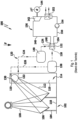
- Figure 1 shows a schematic representation of the basic functionality of a solar thermal power plant 100.
- the solar thermal power plant 100 comprises a heliostat field 102 with a plurality of heliostats 104.
- a heliostat 104 has a mirror surface 106 which can be aligned about at least two axes.
- Solar radiation 108 can be directed via the mirror surfaces 106 of the heliostat field 102, in particular in a bundled manner, onto a solar radiation receiver device 110.
- Solar radiation directed onto the solar radiation receiver device 110 is in Fig. 1 indicated by the reference number 112.
- the solar thermal power plant 100 comprises at least one tower receiver 114, in which the solar radiation receiver device 110 is arranged on a tower 116 at a distance from a base 118 (relative to the direction of gravity g), i.e. is arranged elevated.
- the heliostats 104 are also arranged on the base 118.
- the solar radiation receiver device 110 is designed as a particle solar radiation receiver device which is operated with particles as a heat transfer medium.
- the particles are, for example, ceramic particles.
- bauxite particles with typical diameters of approximately 250 ⁇ m to approximately 1.8 mm are used.
- the heat transfer medium 210 used to transport the heat received from the heliostat field 102 and fed into the solar radiation receiver device 110 of the tower receiver 114 is generally flowable or free-flowing.
- the solar thermal power plant 100 comprises a first circuit 120, which is a particle circuit.
- the first circuit 120 particles are passed through a heat exchanger 122.
- the first circuit 120 has a high-temperature branch 124 and a low-temperature branch 126.
- the low-temperature branch 126 leads from an output 128 of the heat exchanger 122 to an input 130 of the (particle) solar radiation receiver device 110.
- the high-temperature branch 124 leads from an output 132 of the solar radiation receiver device 110 to an input 134 of the heat exchanger 122. Particles can thus be fed to the solar radiation receiver device 110 via the low-temperature branch 126 and are heated there by solar radiation. Heated particles can be fed to the heat exchanger 122 via the high-temperature branch 124 and can release heat there to a second circuit 136.
- a heat storage unit 138 (low-temperature heat storage unit) is optionally arranged in the low-temperature branch 126.
- a heat storage unit 140 (high-temperature heat storage unit) is optionally arranged in the high-temperature branch 124.
- the second circuit 136 is a turbine circuit.
- a turbine 142 in particular a steam turbine, is arranged in it, which is coupled to an electrical generator 144 for generating electrical energy.
- the second circuit 136 comprises a high-temperature branch 146, which leads from an outlet 148 of the heat exchanger 122 to the turbine 142. Furthermore, the second circuit 136 comprises a low-temperature branch 150, which leads from the turbine 142 or a condenser 152 downstream of the turbine to an inlet 154 of the heat exchanger 122.
- a pump 156 is arranged, which pumps a fluid through the second circuit 136.
- the water of the second circuit 136 is heated at the heat exchanger 122, thereby generating steam.
- This steam is fed to the turbine 142 via the high-temperature branch 146 and expanded therein.
- the thermal energy is thereby converted into mechanical energy, which drives the electrical generator 144 to generate electricity.
- the steam is expanded and finally condenses into water in the condenser 152.
- This condensate is returned to the heat exchanger 122 in the low-temperature branch 150 for renewed steam generation.
- a single-stage turbine arrangement is shown. It is also possible for the turbine arrangement to be multi-stage.
- a solar radiation receiver device 110 it is also possible, for example, for a solar radiation receiver device 110 to be used to generate process heat or to effect chemical conversions or to produce fuels. Other applications are also conceivable.
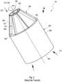
- FIG 2 shows the solar radiation receiver device 110 according to the prior art in an isometric view, while in Figure 3 such a solar radiation receiver device 110 is shown in a transparent representation.
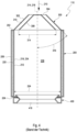
- Figure 4 is the solar radiation receiver device 110 of Figure 3 shown in a longitudinal section.
- the known solar radiation receiver device 110 shown comprises a container 200, which is rotatable about a rotation axis 216 by means of a rotary drive device (not shown), as well as a supply device 300 for supplying the heat transfer medium 210 to an interior 208 of the container 200 and a discharge device 400 for discharging the heat transfer medium 210 from the container 200 (in the Figures 3 and 4 visible), both of which are connected to this container 200.
- the container 200 has a longitudinal axis 214 which is oriented parallel or at an acute angle of typically less than or equal to 80° to the direction of gravity g, which is symbolized in the figure by a vertical arrow.
- the container 200 comprises in particular a hollow cylindrical base body which comprises the circular cylindrical interior 208 surrounded by an outer wall 206.
- An inner wall 218 is arranged at a distance from the outer wall 206 and surrounds the interior 208.
- the container 200 has a thermal insulation 220 between the outer wall 206 and the inner wall 218.
- the axis of rotation 216 forms an angle 222 of typically approximately 45° with the direction of gravity g, wherein the longitudinal axis 214 is expediently aligned coaxially with the axis of rotation 216.
- a lower end 204 of the container 200 with respect to the direction of gravity g is open so that an aperture opening 416 of the container 200 is formed through which solar radiation 112 can enter the interior 208 of the container 200.
- the inner wall 218 of the container 200 is provided with a heat transfer medium 210, which is supplied via the supply device 300 through the supply opening 304.
- the heat transfer medium 210 spreads on the inner wall 218 and thereby forms a heat transfer medium film 212 (see Figure 4 ).
- the heat transfer medium 210 is fed into the interior 208 of the container 200 via the feed device 300, which is arranged at the upper end 202 of the container 200.
- the heat transfer medium 210 can be transported, in particular conveyed, along the inner wall 218 from the end 202 at which it is supplied to an end 204 of the container 200 opposite this end 202, at which the aperture opening 416 is arranged, in order to apply solar radiation 112 to a continuous flow of heat transfer medium 210 and thus to heat it.
- the feed device 300 is formed from a conical front wall 302 and a conical rear wall 308 directed towards the interior 208 of the container 200, which are arranged coaxially and one above the other in the axial direction.
- a cone angle 316 can be, for example, between 30° and 90°, preferably between 45° and 80°.
- guide elements 310 are arranged aligned in the radial direction 238 and are connected to the rear wall 308.
- the guide elements 310 can also be connected to the inner wall 218 or overlapping alternately with the rear wall 308 and the inner wall 218. In the prior art, these guide elements 310 are straight.
- the heat transfer medium 210 is introduced into the feed device 300 via a feed opening 304 arranged in a tip of the conical front wall 302 and is guided between guide elements 310 in the radial direction 238 outwards to the inner wall 218 of the container 200.
- the heat transfer medium 210 is distributed on the inner wall 218 and is guided downwards towards the discharge device 400 by the force of gravity g.
- the inner wall 218 of the container 200 usually has a friction-enhancing device 234 so that the heat transfer medium 210 adheres as well as possible to the inner wall 218 and thus has a sufficiently long residence time in the interior 208 to absorb sufficient heat from the solar radiation 112.
- the heated heat transfer medium 210 is then available for further use, for example for generating electricity in the solar thermal power plant 100 ( Figure 1 ), available.
- the discharge device 400 for discharging the heat transfer medium 210 from the container 200 is arranged at the opposite end 204 of the container 200 and encloses the aperture opening 416, which serves as an inlet for the solar radiation 112.
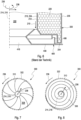
- FIG. 5 a supply device 300 of a solar radiation receiver device 110 according to the prior art is shown in an exploded view.
- the conical front wall 302 opens into the hollow cylindrical feed opening 304 at the tip of the cone.
- the rear wall 308, which is also conical, has a plurality of guide elements 310 which run outwards in the radial direction 238.
- the front wall 302 and the rear wall 308 are arranged on a mounting ring 330 in the intended assembled state.
- Figure 6 shows a longitudinal section through an end 204 of a container 200 with a discharge device 400 according to the prior art.
- the discharge device 400 has a stationary discharge ring 408 in which the container 200 rotates about its axis of rotation 216 in the direction of rotation 236.
- the heat transfer medium 210 slides down the inner wall 218 of the container 200 in the direction of gravity g and is received by the discharge ring 408.
- the heat transfer medium 210 can be discharged from the discharge ring 408 in a suitable manner, for example via a pipe in the bottom of the discharge ring 408 (not shown). To ensure that no heat transfer medium 210 escapes outwards in the radial direction 238 between the outer wall 206 and the discharge ring 408, the outer wall 206 and the discharge device 400 have a type of labyrinth seal 406.
- Embodiments of supply devices 300 are described.
- Embodiments of discharge devices 400 are described.
- the described feed devices 300 and discharge devices 400 can be used in any combination with one another in a solar radiation receiver device 110.
- the feed devices 300 can be combined with known discharge devices.
- the discharge devices 400 can be combined with known feed devices.
- the proposed feed devices 300 and discharge devices 400 can be combined with the Figures 12 to 16 described advantageous embodiments of the container 200 can be combined as desired or with embodiments of the container 200 from the prior art.
- the Figures 7 to 11 The described embodiments of feed devices 300 each have an outer front wall 302 and an inner rear wall 308.
- the front wall 302 adjoins the outer wall 206 of the container 200.
- the supply devices 300 make it possible to even out the spatial distribution of the heat transfer medium 210, in particular the particles, according to the invention.
- the basic functional structure of the solar radiation receiver device 110 with supply device 300, container 200, discharge device 400 largely corresponds to the known structure as described above. To avoid unnecessary repetition of the known elements, reference is made to the previous figure descriptions.
- Figure 7 shows a feed device 300 according to an embodiment of the invention in a plan view of a rear wall 308 on which curved guide elements 310 are arranged.
- a plurality of curved guide elements 310 extending in the radial direction 238 are arranged between the front wall 302 and the rear wall 308 of the feed device 300.
- the container 200 ( Figure 2 , 3
- the co-rotating rear wall 308 has guide elements 310 which protrude from the rear wall 308 in the direction of the front wall 302 and are particularly perpendicular to the rear wall 308 and are designed, for example, as welded-on sheets.
- the guide elements 310 are designed in a sickle shape.
- the guide elements 310 are curved against the direction of rotation 236, ie the guide elements 310 consequently have a change in direction when passing through in the radial direction 238 from radially inside to radially outside, which is opposite to the direction of rotation 236.
- the particles of the heat transfer medium 210 are fed centrally through the feed opening 304.
- the curved guide elements 310 reduce the speed of the heat transfer medium 210 in the radial direction 238 and thereby increase the residence time in the area of the guide elements 310. During this time, the particles absorb heat via the rear wall 308 and the guide elements 310 and thus simultaneously cool the rear wall 308.
- the guide elements 310 are advantageously curved in such a way that the particles in the radially outer region are deflected in such a way that the radial, outward-directed velocity component is reduced.
- the curvature can take place in the direction of rotation 236 or against the direction of rotation 238.
- the guide elements 310 have good thermal contact with the rear wall 308.
- the guide plates 310 and the rear wall 308 are advantageously designed so that the particles have as good and long a contact as possible with these surfaces in order to absorb as much heat as possible for cooling the rear wall 308 and for preheating the particles.
- the guide elements 310 are arranged on the rear wall 308 of the feed device 300. However, in other embodiments, the guide elements 310 can also be connected to the inner wall 206 or overlapping alternately with the rear wall 308 and the inner wall 206. In particular, a height 312 (see definition of height 312 in Figure 2 ) of the respective guide element 310 at least partially and/or in sections a distance 328 ( Figure 2 ) between front wall 302 and rear wall 308.
- the guide elements 310 can thus have a limited height 312. In this case, particles can flow outwards more quickly in the radial direction 238 via the guide elements 310 at high mass flows of particles.
- a distribution device 322 is arranged on a radial outer edge of the rear wall 308 and is designed to even out the spatial distribution of the heat transfer medium 210.
- the particles of the heat transfer medium 210 can enter as evenly as possible over the inner wall of the container 200.
- the distribution device 322 can be designed as a cylinder segment, for example from a perforated sheet.
- the distribution device 322 has the function of allowing the particles to flow out evenly over the circumference even when the previous outlets are locally limited by an exit from the guide plates.
- FIG 8 a top view of a rear wall 308 of a feed device 300 according to a further embodiment of the invention is shown.
- the guide element 310 runs spirally from the feed opening 304 in the radial direction 238 to the radially outside. In this case too, the guide element 310 is curved spirally around the axis of rotation 214 against the direction of rotation 236 and thus slows down the speed of the particles of the heat transfer medium 210.
- the guide element 310 is preferably designed in a spiral shape so that the particles slowly slide downwards along the guide element 310 and the rear wall 308. Such a function can also be carried out via several spiral-shaped guide elements 310.
- the guide elements 310 have good thermal contact with the rear wall 308.
- the spiral design of the guide element 310 ensures that the particles only reach the distribution device 322 after several revolutions of the rear wall 308.
- the distribution device 322 can be designed as a cylinder segment, for example made of a perforated sheet.
- the distribution device 322 has the function of allowing the particles to flow out evenly over the circumference even when the previous outlets are locally limited by an exit from the guide plates.
- Figure 9 shows a longitudinal section through a feed device 300 with an outer front wall 302 and an inner rear wall 308 according to a further embodiment of the invention, in which the rear wall 308 is shortened in the axial direction compared to the front wall 302.
- the conical front wall 302 adjoins the outer wall 206 of the container 200 at its maximum diameter.
- outer wall 206 and inner wall 218 are shown simplified without thermal insulation.
- a maximum diameter 314 of the conical rear wall 308 of the feed device 300 is smaller than an inner diameter 224 of the inner wall 218 of the container 200.
- the diameter 314 of the rear wall 308 can be at most 95%, preferably at most 60%, of the inner diameter 224 of the inner wall 218 of the container 200.
- the front wall 302 and the rear wall 308 of the feed device 300 are conical.
- a cone angle 316 can be between 30° and 90°, preferably between 45° and 80°.
- the feed opening 304 is preferably arranged in a tip of the cone.
- the feed opening 304 can be arranged eccentrically.
- the inner cone of the feed device 300 designed as the rear wall 308, can thus be built shorter than is usual in the prior art.
- the radial position of the particles of the heat transfer medium 210 can be determined, from which point they no longer slide over the rear wall 308, but are initially pressed by the centrifugal force onto the outer cone of the front wall 302 of the feed device 300, from where they are guided onto the inner wall 218 of the container 200.
- the flow of the heat transfer medium 210 is shown in the figure as a wave-shaped arrow 324, which indicates that the particles first reach the outside of the rear wall 308 from the feed opening 304, from there change from a certain lifting point 325 to an impact point 327 on the inside of the front wall 302 and from there finally reach the inner surface 218.
- a part of the inner cone of the rear wall 308 in the area between the lifting point 325 of the particles from the rear wall 308 and the inner wall 218 can be saved. Instead, an annular gap 326 is formed there. This enables early solar irradiation of the particles already in the feed. This can reduce the manufacturing costs of the feed device 300. Furthermore, the heating of the particles can be improved. Consequently, shorter containers 200 can be used.
- FIG 10 is a plan view of a configuration of a feed device 300 according to a further embodiment of the invention, while in Figure 11 a longitudinal section of the feed device 300 is shown.
- the rear wall 308 of the feed device 300 is not conical, but is designed as a flat surface which is aligned obliquely, preferably perpendicularly, to the longitudinal axis 214.
- a cone 318 with a conical tip 320 directed towards the feed opening 304 is arranged in the longitudinal axis 214 for distributing the heat transfer medium 210.
- the front wall 302 can also be designed not conical but as a flat surface.
- the usual conical structure of the feed device 300 with a cone angle of up to 45° is advantageously replaced by a simplified flat funnel without an angle of inclination.
- guide elements 310 such as guide plates welded to the outside of the rear wall 308 can also be arranged. These can, for example, be used pre-bent and only welded at the ends in the radial direction 238.
- the pre-bending determines the direction of buckling when the guide elements 310 thermally expand in length.
- the pre-bending of the guide elements 310 also has the advantage that the point at which the particles are delivered from the feed device 300 to the inner wall 218 of the container 200 can be conveniently moved closer to the feed device 300.
- the cone 318 is arranged in the center of the flat funnel and gently deflects the particles fed in from a stationary pipe as a feed opening in the radial direction 238.
- the particles can be fed in the upper quarter of the cone 318, for example, so that they can be delivered to the inner wall 218 of the container 200 at the lower circumference if possible. This design allows the components to be made more cost-effective and space-saving.
- Figure 12 shows a longitudinal section through a container 200 with a conveyor device 230 and blade-like guide structures 228 arranged thereon according to a further embodiment of the invention.
- Figure 13 is another longitudinal section through the container 200, and in Figure 14 a cross-section through the container 200 is shown.
- At least one conveying device 230 is arranged in the interior 208 of the container 200, which is parallel or slightly inclined, in particular less than 10°, preferably less than 5°, to the longitudinal axis 214 and adjacent to the inner wall 218, and which has guide structures 228, in particular blade-like guide structures 228, distributed over its length.
- the guide structures 228 are designed to convey the heat transfer medium 210 in the direction of the first end 202 or the second end 204 of the container 200 when the container 200 is rotating.
- the conveying device 230 is fixedly connected to a receiving device (not shown) arranged outside the container 200.
- the conveying device 230 which for example has a holding device that can be designed as a tube or grid, can preferably be arranged at both ends so that it does not rotate, ie is held firmly.
- the conveying device 230 can preferably, like the guide structures 228, be designed to be high temperature resistant, for example from silicon carbide.
- the holding device can be used to supply particles via the rear wall 308.
- a suitable discharge device can then be attached to the lower end of the tube, for example so that the particles flow out in the direction of rotation of the cylinder wall 206.
- the particles of the heat transfer medium 210 can also be supplied via the edge region of the aperture opening 416 at the second end 204 of the container 200.
- the blade-like guide structures 228 are designed such that the particles of the heat transfer medium 210, which move past the blades 228 with the rotating container wall 206, are displaced in the direction of the rotation axis 216 by approximately one blade height during one revolution, for example in the direction of the rear wall 308, or alternatively in the direction of the aperture opening 416.
- a firmly defined particle sublayer of the heat transfer medium film 212 can be created, whereby the particles deposited above it are lifted off and transported.
- significantly larger tolerances can be permitted for the inner wall 218 of the container 200, which are compensated by the stationary particle sublayer.
- the conveying device 230 can also be designed to forward the heat transfer medium 210 supplied at the supply-side first end 202 of the container 200 via the supply device 300 to the discharge-side second end 204.
- the heat transfer medium 210 with low temperature is supplied to the end 204 of the container 200, at which heated heat transfer medium 210 is present.
- the particle supply can also take place through the aperture opening 416 or alternatively via the conveying device 230 from the opposite end 202 to the aperture opening 416.
- the particle supply into the container 200 takes place from the end 202 of the container 200 facing away from the aperture opening 416.
- blade-like guide structures 228 can advantageously be arranged on the conveying device 230.
- the conveying device 230 can supply the particles at a low temperature to the discharge end 204 of the container 200. This allows the conveying device 230 to be cooled at the same time.
- the conveying device 230 can also be designed to convey the heated heat transfer medium 210 from the second end 204 on the aperture side to the first end 202 facing away from the aperture opening 416. In this way, the temperature distribution in the container 200 can be made more uniform. The particles can be removed, for example, through an overflow at the feed-side end 202 of the container 200.
- the conveying device 230 can be arranged in the intended state of use with respect to a direction of gravity g in an upper region 232 of the interior 208 of the container 200 with respect to the direction of gravity g.
- the conveying device can also be arranged on an area of the inner side 218 of the container 200 that is not irradiated by solar radiation, i.e. on a side that is at the bottom with respect to the direction of gravity g.
- Such an arrangement can possibly be advantageous for certain granules, although the particles stick together more firmly.
- this area 232 is mainly hit by concentrated solar radiation from heliostats 104 ( Figure 1 ) located close to the tower receiver 114 ( Figure 1 ) and thus produce comparatively small focal spots that can be shifted slightly to the side using a target point strategy. This reduces the load on a holding device of the solar radiation receiver device 200.
- the inner wall 218 of the container 200 can have a plurality of distributed guide structures 228, in particular blade-like guide structures 228, which are designed to convey the heat transfer medium 210 in the direction of the supply-side end 202 when the container 200 is rotating.
- the heat transfer medium 210 is only present in a partial area of the container 200 and is displaced by the guide structures 228 as it slides.
- the particle movement of the heat transfer medium 210 in the container 200 occurs essentially due to gravity.
- the container 200 is inclined with the aperture opening 416 facing downwards. The highest temperatures occur near the aperture opening 416.
- the temperature profile in the interior of the container 200 can be changed so that the highest temperatures occur near the rear wall 308 deep inside the container 200. This can advantageously reduce the thermal losses due to thermal radiation and convection.
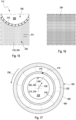
- Figure 15 shows a plan view of an inner wall 218 of a container 200 with a friction-enhancing device 234 arranged thereon according to a further embodiment of the invention.
- the friction-enhancing device 234 can be seen in an enlarged view.
- the friction-promoting device 234 can be manufactured on the inner wall 218 of the container 200 using an additive manufacturing process and connected directly to the inner wall 208 of the container 200.
- the friction-promoting device 234 can thus be designed in the form of a grid, for example, but other structures on the inner wall 218 of the container can also be advantageous.
- a grid that is usually welded onto the inner wall 218 of the container 200 as a friction-enhancing device can advantageously be replaced by structuring using an additive manufacturing process such as 3D printing.
- the device manufactured by 3D printing can be applied before or after the container 200 is manufactured.
- 3D printing has several advantages. For example, any type of structuring can be applied flexibly.
- different structures or mesh sizes of a grid-like structure can be arranged on different areas of the inner wall 218 of the container 200.
- the friction-promoting device 234 can be firmly connected as a structure to the inner wall 218 of the container 200 so that it cannot lift off.
- the basic functional structure of the solar radiation receiver device 110 with feed device 300, container 200, and discharge device 400 largely corresponds to the known structure as described above. To avoid unnecessary repetition of the known elements, reference is made to the previous descriptions of the figures.
- the proposed feed devices 300 advantageously enable a reduction in the risk of losing particles when discharging them from the container 200.
- FIG 17 shows a cross section through a discharge device 400 according to a further embodiment of the invention with a device 402 with blade-like guide elements 410.
- Figure 18 a longitudinal section through the discharge device 400 is shown.
- the device 402 has a plurality of guide elements 410 projecting in a radial direction 238, which are arranged at the discharge-side end 204 of the container 200 between the outer wall 206 and the discharge device 400.
- the device 402 rotates with the container 200 and engages with the guide elements 410 in the fixed discharge ring 408.
- the guide elements 410 are curved along their extension between the inner wall 218 and the outer wall 206 in the direction of the intended direction of rotation 236.
- a plurality of equidistantly arranged guide elements 410 can be provided, which are curved in a sickle-like manner, for example.
- Radial blades are arranged as guide elements 410 on the discharge-side end 204 of the rotating container 200 at the transition to the static collecting ring 408 of the discharge device 400. Particles of the heat transfer medium 210 slide along the inner wall 218 of the container 200 downwards into the discharge ring 408 of the discharge device 400.
- the guide elements 410 redirect the particles and accelerate the particles in the rotating reference system so that they have a significantly lower speed in the stationary reference system. In this way, the abrasion caused by the particles in the collecting ring 408 inevitably colliding with one another can be reduced.
- the abrasion on the collecting ring 408 can be greatly reduced in particular by reducing the impact speed of the particles. If the abrasion is too great, particles must be replaced from time to time. Furthermore, the loss of particles can be reduced. The lower the particle loss at this point, the fewer particles need to be reintroduced into the system over time.
- the guide elements 410 can also be designed in a spiral shape, running radially outward from the inner wall 218.
- the spiral shape of the guide elements 410 allows particles of the heat transfer medium 210 to be effectively slowed down in order to reduce abrasion caused by collisions when the particles are removed. The lower the particle loss at this point, the fewer particles have to be fed back into the system over time.
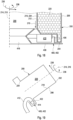
- Figure 19 shows a longitudinal section through one end of a container 200 with a discharge device 400 according to a further embodiment of the invention with a pipe 412 at the discharge end 204 of the container 200 for discharging the heat transfer medium 210 from the container 200.
- the pipe 412 is firmly connected to a receiving device (not shown) arranged outside the container 200.
- the pipe 412 is arranged at the discharge-side end 204 of the container 200 with a pipe opening 414 opposite to the intended direction of rotation 236 of the container 200 and is designed to receive the heated heat transfer medium 210.
- the container 200 has, at the discharge-side end 204, a bulge 432 which extends radially outward from the outer wall 206 and runs around a circumference of the container 200 and into which the pipe opening 414 projects.
- the pipe 412 can be arranged at the discharge-side end 204 of the container 200 with the pipe opening 414 opposite to the intended direction of rotation 236 of the container 200.
- the particles of the heat transfer medium 210 do not leave the rotating part of the container 200 as in the prior art via the simple axial movement over the lower end 204 of the cylindrical rotating container 200, where the particles are collected in a circumferential ring.
- the particles are collected by a tube 412 that is stationary relative to the environment. This is attached tangentially to the lower end 204 of the rotating container 200.
- a radially outwardly projecting bulge 432 can be attached to the end 204 of the outer wall 206 of the rotating container 200, into which the fixed tube 412 projects.
- the bulge 432 significantly increases the probability that all particles leave the container 200 via the tube 412.
- the pipe 412 can be connected to a suction device so that the heated heat transfer medium is sucked into the pipe opening 414.
- the particles of the heat transfer medium 210 can be sucked out using negative pressure.
- dust can also be removed and separated by the extraction, which can minimize optical radiation losses due to dust in the air in the interior 208 of the container 200 and also means that less dust is released into the environment.
- a fluid flow, in particular compressed air, directed towards the pipe opening 414 can be provided, which is designed to transport the heated heat transfer medium 210 into the pipe opening 414.
- the particles of the heat transfer medium 210 can be blown into the tangentially arranged pipe 412 in a targeted manner using compressed air. This can also be done in combination with the suction of the particles using negative pressure.
- FIG 20 is an isometric representation of a section of a discharge device 400 according to a further embodiment of the invention with a discharge ring 408 integrated into a radiation shield.
- the device 402 has a channel 409 formed by a discharge ring 408 and a radially externally delimiting ring structure 436 as a collecting ring, the ring structure 436 having a discharge opening 434 for the exit of the heated heat transfer medium 210, ie the particles.
- the discharge ring 408 with channel 409 and ring structure 436 is connected to a plate 418 designed as radiation protection against the incident solar radiation 112.
- the plate 418 can be designed with insulation and/or with a fluid cooling device on at least one side 442.
- the channel 409 serves to collect the particles of the heat transfer medium 210.
- the particles can be discharged to the outside via the discharge opening 434.
- the discharge ring 408 with the channel 409 and the ring structure 436 of the discharge device 400 can be integrated into the plate 418 designed as radiation protection, whereby manufacturing costs and assembly effort can be reduced.
- the plate 418 of the discharge device 400 integrated into the radiation protection can advantageously be insulated on both sides and, for example, actively cooled via a fluid cooling device so that the support structure does not fail.
- the discharge ring 408 with channel 409 and ring structure 436 can be applied as a collecting ring, while the other side 442 of the plate 418 can be designed directly as radiation protection insulation. This can further reduce the manufacturing costs of the discharge device 400.
- Figure 21 shows a longitudinal section through a discharge device 400 according to a further embodiment of the invention with a cover 420 which is designed as a radial labyrinth seal.
- the discharge device 400 comprises a device 402 which has a cover 420 arranged at the discharge-side end 204 of the container 200 and acting in the radial direction.
- the device 402 also has a shoulder 440 which is directed radially outwards at the discharge-side end 204 of the wall of the container 200 and which projects radially outwards beyond the outer wall 206.
- the shoulder 440 is surrounded by the cover 420 in the form of a labyrinth cover.
- the cover 420 is also surrounded by a thermal insulation 424 which acts in the radial direction 238 and in the axial direction 214.
- the cover 420 can be designed, for example, as a radial labyrinth seal made of sheet metal. This can improve the sealing of the discharge device 400 and prevent particle loss due to particles escaping from the discharge device 400. The lower the particle loss at this point, the fewer particles have to be fed back into the system over time. This could further reduce operating costs.
- the shoulder 440 arranged at the discharge-side end 204 of the wall of the container 200 advantageously represents a further improvement of the seal between the fixed discharge device 400 and the outer wall 206 of the rotating container 200.
- a thermal insulation 424 which surrounds the cover 420 to the outside, can advantageously provide further potential for a higher efficiency when using the solar radiation receiver device 110 according to the invention.
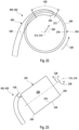
- FIG 22 shows a cross section through a discharge device 400 according to a further embodiment of the invention with a collecting device 426 which radially discharges the heat transfer medium 210.
- Figure 23 an enlarged longitudinal section through the discharge device 400 is shown.
- the discharge device 400 comprises a device 402 which has a collecting device 426 leading outwards in the radial direction 238, in particular in a spiral shape, from the outer wall 206 at the discharge-side end 204 of the container 200.
- the collecting device 426 which is designed as part of a discharge ring, is firmly connected to a receiving device arranged outside the container 200, i.e. is installed in a fixed position.
- the collecting device 426 has an inlet opening 430 which is directed towards the container 200 in the opposite direction to the intended direction of rotation 236 of the container 200 and which serves to discharge the heated heat transfer medium 210.
- a discharge ring 408 (not shown) which runs around a circumference of the outer wall 206 can be arranged at the discharge-side end 204 of the container 200 and into which the collecting device 426 opens with its inlet opening 430.
- the end of the inlet opening 429 is located approximately in the area in which the collecting device 426 is guided away from the wall 206 of the container 200.
- the outlet region 428 in which the particles of the heat transfer medium 210 leave the container, is located in the front region of the discharge device 400, starting at the inlet opening 430.
- the particle discharge which actually only occurs locally, is used to remove the particles locally.
- the natural particle trajectory in the rotating container 200 is reproduced in order to remove the particles from the container 200.
- This can reduce the collision speed of particles to the inlet opening 430 of a discharge pipe as a collection device 426. In this way, the erosion of particles and collection device 426 can be reduced and possible dust formation can be reduced. The lower the particle loss at this point, the fewer particles have to be fed back into the system over time.
- a reduced ring-shaped collecting device 426 for the particles can also be used in a rotating manner to carry out other particle discharge, for example when the operating mode changes or when wind occurs.
Landscapes
- Engineering & Computer Science (AREA)
- Chemical & Material Sciences (AREA)
- Life Sciences & Earth Sciences (AREA)
- Sustainable Development (AREA)
- Sustainable Energy (AREA)
- Thermal Sciences (AREA)
- Physics & Mathematics (AREA)
- Combustion & Propulsion (AREA)
- Mechanical Engineering (AREA)
- General Engineering & Computer Science (AREA)
- Filling Or Emptying Of Bunkers, Hoppers, And Tanks (AREA)
- Engine Equipment That Uses Special Cycles (AREA)
- Heat-Exchange Devices With Radiators And Conduit Assemblies (AREA)
Claims (15)
- Dispositif de réception de rayonnement solaire (110) destiné à chauffer un milieu caloporteur (210) dans une centrale solaire thermique (100), ledit dispositif comprenant- un récipient (200) qui est pourvu de deux extrémités opposées (202, 204) et qui comprend une paroi extérieure (206) et un espace intérieur (208) entouré par la paroi extérieure (206) ;- un module d'alimentation (300) destiné à amener le milieu caloporteur (210) à l'espace intérieur (208) du récipient (200), le dispositif d'alimentation (300) étant disposé à l'une des extrémités (202, 204) du récipient (200) ;- un module d'évacuation (400) destiné à évacuer le milieu caloporteur (210) du récipient (200), le module d'évacuation (400) étant disposé à la même extrémité ou à l'extrémité opposée (202, 204) du récipient (200) ; ainsi que- une ouverture (416) destinée à l'entrée du rayonnement solaire à l'une des extrémités (202, 204) ;le récipient (200) ayant un axe longitudinal (214) qui est orienté parallèlement au sens de gravité (g) ou suivant un angle aigu inférieur à 90° par rapport à celui-ci, le récipient (200) pouvant tourner sur un axe de rotation (216) dans un sens de rotation prévu (236) au moyen d'un dispositif d'entraînement en rotation du dispositif de réception de rayonnement solaire (110) de manière à ce que le milieu caloporteur (210) puisse être guidé le long d'une paroi intérieure (218) du récipient (200) en formant un film de milieu caloporteur (212),la paroi intérieure (218) du récipient (200) comportant un module de promotion de friction (234),le module d'alimentation (300) comportant une paroi avant (302) pourvue d'une ouverture d'alimentation (304) et une paroi arrière (308) dirigée vers l'espace intérieur (208) du récipient (200),au moins un élément de guidage (310) qui s'étend au moins dans une direction radiale (238) étant disposé entre la paroi avant (302) et la paroi arrière (308), caractérisé en ce que l'élément de guidage est incurvé le long de son extension entre l'ouverture d'alimentation (304) et la paroi extérieure (206) dans un sens opposé au sens de rotation prévu (236).
- Dispositif de réception de rayonnement solaire selon la revendication 1, caractérisé en ce que le milieu caloporteur (210) est fluide ou coulant, en particulier en ce que le milieu caloporteur (210) est formé par des particules.
- Dispositif de réception de rayonnement solaire selon la revendication 1 ou 2, caractérisé en ce que l'axe de rotation (216) est placé parallèlement au sens de gravité (g) ou suivant un angle aigu (222) inférieur ou égal à 90°, de préférence inférieur ou égal à 80°, par rapport à celui-ci, notamment en ce que l'axe de rotation (216) est coaxial à l'axe longitudinal (214) du récipient (200) .
- Dispositif de réception de rayonnement solaire selon l'une des revendications précédentes, caractérisé en ce que l'au moins un élément de guidage (310) est disposé sur la paroi arrière (308), notamment une hauteur (312) de l'au moins un élément de guidage (310) correspondant au moins partiellement et/ou par portions à une distance (328) entre la paroi avant (302) et la paroi arrière (308) .
- Dispositif de réception de rayonnement solaire selon l'une des revendications précédentes, caractérisé en ce que l'au moins un élément de guidage (310) s'étend en spirale dans une direction radiale (238) vers l'extérieur depuis l'ouverture d'alimentation (304).
- Dispositif de réception de rayonnement solaire selon la revendication 5, caractérisé en ce qu'un module de distribution (322), qui est conçu pour égaliser une distribution spatiale du milieu caloporteur (210), est disposé sur un bord extérieur de la paroi arrière (308).
- Dispositif de réception de rayonnement solaire selon l'une des revendications précédentes, caractérisé en ce qu'un diamètre (314) de la paroi arrière (308) du module d'alimentation (300) est inférieur à un diamètre intérieur (224) du récipient (200), en particulier en ce que le diamètre (314) de la paroi arrière (308) représente au plus 95 %, de préférence au plus 60 %, du diamètre intérieur (224) du récipient (200).
- Dispositif de réception de rayonnement solaire selon l'une des revendications précédentes, caractérisé en ce que la paroi avant (302) et la paroi arrière (308) du dispositif d'alimentation (300) sont coniques, notamment en ce qu'un angle de cône (316) est compris entre 30° et 90°, de préférence entre 45° et 80°, en particulier en ce que l'ouverture d'alimentation (304) est disposée au sommet du cône.
- Dispositif de réception de rayonnement solaire selon l'une des revendications 1 à 7, caractérisé en ce qu'au moins la paroi arrière (308) du module d'alimentation (300) est conçue comme une surface plane qui est orientée obliquement, de préférence perpendiculairement, à l'axe longitudinal (214), un cône (318) dont le sommet de cône (320) est dirigé vers l'ouverture d'alimentation (304) et qui est destiné à distribuer le milieu caloporteur (210) étant disposé dans l'axe longitudinal (214).
- Dispositif de réception de rayonnement solaire selon l'une des revendications précédentes, caractérisé en ce que la paroi intérieure (218) du récipient (200) comporte des structures de guidage (228) disposées de manière répartie, en particulier des structures de guidage (228) de type pales qui sont conçues pour transporter le milieu caloporteur (210), lorsque le récipient (200) est en rotation, en direction de l'extrémité côté alimentation ou côté évacuation (202, 204).
- Dispositif de réception de rayonnement solaire selon l'une des revendications 1 à 9, caractérisé en ce qu'au moins un dispositif de transport (230), en particulier un tube, est disposé dans l'espace intérieur (208) du récipient (200) en s'étendant parallèlement ou de manière légèrement inclinée, notamment inclinée à moins de 10°, de préférence inclinée à moins de 5°, par rapport à l'axe longitudinal (214) et de manière adjacente à la paroi extérieure (206), lequel dispositif de transport comporte des structures de guidage (228), en particulier des structures de guidage (228) de type pales, qui sont disposées de manière répartie sur sa longueur et qui sont conçues pour transporter le milieu caloporteur (210), lorsque le récipient (200) est en rotation, en direction de la première extrémité (202) ou de la deuxième extrémité (204), le dispositif de transport (230) étant relié de manière fixe à un module de réception disposé à l'extérieur du récipient (200).
- Dispositif de réception de rayonnement solaire selon la revendication 11, caractérisé en ce que le dispositif de transport (230) est conçu pour acheminer à la deuxième extrémité (204) le milieu caloporteur (210) qui a été amené par le module d'alimentation 300) à la première extrémité (202) du récipient (200).
- Dispositif de réception de rayonnement solaire selon la revendication 11, caractérisé en ce que le dispositif de transport (230) est conçu pour acheminer le milieu caloporteur chauffé (210) de la deuxième extrémité (204) à la première extrémité (202).
- Dispositif de réception de rayonnement solaire selon l'une des revendications 11 à 13, caractérisé en ce que le dispositif de transport (230) est disposé dans l'état d'utilisation prévu par rapport au sens de gravité (g) dans une zone supérieure (232) de l'espace intérieur (208) .
- Dispositif de réception de rayonnement solaire selon l'une des revendications précédentes, caractérisé en ce que le module de promotion de friction (234) est fabriqué sur la paroi intérieure (218) du récipient (200) au moyen d'un procédé de fabrication additive et est relié à la paroi extérieure (206), en particulier en ce que le module de promotion de friction (234) est conçu sous forme de grille sur la paroi intérieure (218) du récipient (200).
Applications Claiming Priority (4)
| Application Number | Priority Date | Filing Date | Title |
|---|---|---|---|
| DE102020132497 | 2020-12-07 | ||
| DE102020132498 | 2020-12-07 | ||
| DE102020132496 | 2020-12-07 | ||
| PCT/EP2021/075011 WO2022122202A1 (fr) | 2020-12-07 | 2021-09-10 | Appareil récepteur de rayonnement solaire pour chauffer un milieu de transfert de chaleur dans une centrale héliothermique |
Publications (3)
| Publication Number | Publication Date |
|---|---|
| EP4256247A1 EP4256247A1 (fr) | 2023-10-11 |
| EP4256247C0 EP4256247C0 (fr) | 2024-11-20 |
| EP4256247B1 true EP4256247B1 (fr) | 2024-11-20 |
Family
ID=77998950
Family Applications (3)
| Application Number | Title | Priority Date | Filing Date |
|---|---|---|---|
| EP21782645.2A Active EP4256247B1 (fr) | 2020-12-07 | 2021-09-10 | Appareil récepteur de rayonnement solaire pour chauffer un milieu de transfert de chaleur dans une centrale héliothermique |
| EP21782646.0A Pending EP4256248A1 (fr) | 2020-12-07 | 2021-09-10 | Appareil récepteur de rayonnement solaire pour chauffer un milieu de transfert de chaleur dans une centrale héliothermique |
| EP21782889.6A Active EP4256249B1 (fr) | 2020-12-07 | 2021-09-10 | Appareil récepteur de rayonnement solaire pour chauffer un agent caloporteur dans une centrale héliothermique |
Family Applications After (2)
| Application Number | Title | Priority Date | Filing Date |
|---|---|---|---|
| EP21782646.0A Pending EP4256248A1 (fr) | 2020-12-07 | 2021-09-10 | Appareil récepteur de rayonnement solaire pour chauffer un milieu de transfert de chaleur dans une centrale héliothermique |
| EP21782889.6A Active EP4256249B1 (fr) | 2020-12-07 | 2021-09-10 | Appareil récepteur de rayonnement solaire pour chauffer un agent caloporteur dans une centrale héliothermique |
Country Status (4)
| Country | Link |
|---|---|
| EP (3) | EP4256247B1 (fr) |
| DE (3) | DE112021006340A5 (fr) |
| ES (2) | ES3000095T3 (fr) |
| WO (3) | WO2022122202A1 (fr) |
Families Citing this family (2)
| Publication number | Priority date | Publication date | Assignee | Title |
|---|---|---|---|---|
| US20250003639A1 (en) * | 2023-06-30 | 2025-01-02 | Heliogen Holdings, Inc. | Modular inliner assembly for a centrifugal particle receiver |
| US12392526B2 (en) | 2023-10-09 | 2025-08-19 | Heliogen Holdings, Inc. | Rotating collector ring for centrifugal solar receiver |
Family Cites Families (8)
| Publication number | Priority date | Publication date | Assignee | Title |
|---|---|---|---|---|
| DE707174C (de) * | 1936-03-17 | 1941-06-16 | Georg Zotos Dipl Ing Dr | Verfahren und Einrichtungen zum Durchsetzen von Arbeitsgut in Schnelldrehoefen |
| EP0052430B1 (fr) * | 1980-11-17 | 1984-06-27 | F.L. Smidth & Co. A/S | Procédé et dispositif pour le traitement thermique d'une matière pulvérulente |
| EP0509286A1 (fr) * | 1991-04-16 | 1992-10-21 | Schweizerische Eidgenossenschaft PAUL SCHERRER INSTITUT | Réacteur |
| US5947114A (en) * | 1995-02-15 | 1999-09-07 | Yeda Research And Development Company Ltd. | Central solar receiver with a multi component working medium |
| DE102010062367A1 (de) | 2010-12-02 | 2012-02-16 | Deutsches Zentrum für Luft- und Raumfahrt e.V. | Solarstrahlungsempfängervorrichtung und Verfahren zur solaren Erhitzung von Wärmeträgermedium |
| DE102014106320B4 (de) | 2014-05-06 | 2020-10-29 | Deutsches Zentrum für Luft- und Raumfahrt e.V. | Solarstrahlungsempfängervorrichtung |
| DE102017219374B4 (de) * | 2017-10-27 | 2019-05-29 | Deutsches Zentrum für Luft- und Raumfahrt e.V. | Solarreceiver sowie Verfahren zum Betrieb eines Solarreceivers |
| CN211084796U (zh) * | 2019-11-22 | 2020-07-24 | 保靖县中锦环保有限公司 | 一种防堵塞回转窑 |
-
2021
- 2021-09-10 EP EP21782645.2A patent/EP4256247B1/fr active Active
- 2021-09-10 WO PCT/EP2021/075011 patent/WO2022122202A1/fr not_active Ceased
- 2021-09-10 ES ES21782645T patent/ES3000095T3/es active Active
- 2021-09-10 EP EP21782646.0A patent/EP4256248A1/fr active Pending
- 2021-09-10 WO PCT/EP2021/075014 patent/WO2022122204A1/fr not_active Ceased
- 2021-09-10 WO PCT/EP2021/075013 patent/WO2022122203A1/fr not_active Ceased
- 2021-09-10 DE DE112021006340.5T patent/DE112021006340A5/de active Pending
- 2021-09-10 EP EP21782889.6A patent/EP4256249B1/fr active Active
- 2021-09-10 DE DE112021006345.6T patent/DE112021006345A5/de active Pending
- 2021-09-10 ES ES21782889T patent/ES3000387T3/es active Active
- 2021-09-10 DE DE112021006337.5T patent/DE112021006337A5/de active Pending
Also Published As
| Publication number | Publication date |
|---|---|
| EP4256247C0 (fr) | 2024-11-20 |
| ES3000387T3 (en) | 2025-02-28 |
| ES3000095T3 (en) | 2025-02-27 |
| WO2022122202A1 (fr) | 2022-06-16 |
| WO2022122204A1 (fr) | 2022-06-16 |
| EP4256249A1 (fr) | 2023-10-11 |
| EP4256249B1 (fr) | 2024-11-20 |
| EP4256247A1 (fr) | 2023-10-11 |
| DE112021006345A5 (de) | 2023-10-19 |
| EP4256248A1 (fr) | 2023-10-11 |
| EP4256249C0 (fr) | 2024-11-20 |
| DE112021006340A5 (de) | 2023-10-19 |
| WO2022122203A1 (fr) | 2022-06-16 |
| DE112021006337A5 (de) | 2023-10-19 |
Similar Documents
| Publication | Publication Date | Title |
|---|---|---|
| EP4256247B1 (fr) | Appareil récepteur de rayonnement solaire pour chauffer un milieu de transfert de chaleur dans une centrale héliothermique | |
| DE102011006066B4 (de) | Wasserseparator und Verfahren zum Abtrennen von Wasser aus einer Nassdampfströmung | |
| EP2539661B1 (fr) | Procédé et dispositif pour stocker et distribuer de la chaleur au moyen d'un matériau à changement de phase | |
| DE2948168A1 (de) | Apparat zum abscheiden von feststoffpartikeln aus einem gasstrom | |
| EP3296462B1 (fr) | Installation et procédé de fabrication d'asphalte | |
| EP0703288A1 (fr) | Enceinte chauffante pour matériaux solides équipée de tubes chauffants | |
| EP3795936A1 (fr) | Système d'accumulation destiné à l'accumulation thermochimique de l'énergie et procédé de fonctionnement d'un système d'accumulation | |
| EP2384415A2 (fr) | Module absorbeur solaire et agencement d'absorbeurs solaires | |
| EP3282024B1 (fr) | Fours à charge pour produit incandescent et procédé de traitement de la chaleur | |
| WO2012072677A2 (fr) | Dispositif récepteur de rayonnement solaire et procédé de chauffage solaire d'un fluide caloporteur | |
| DE102015204461B4 (de) | Solarkraftwerk | |
| DE3830153A1 (de) | Pyrolysereaktor mit indirekter und direkter beheizung | |
| DE102010063116A1 (de) | Solarstrahlungsempfängervorrichtung | |
| AT510573A4 (de) | Windkraftanlage | |
| EP3349911B1 (fr) | Dispositif refroidissant pour une transmission d'une centrifugeuse à vis à bol plein | |
| AT523838B1 (de) | Windkraftanlage | |
| DE102019215002A1 (de) | Dampferzeuger | |
| EP3059409A1 (fr) | Dispositif de traitement des gaz d'echappement | |
| AT18094U1 (de) | Gasdurchlassmodul für einen hochtemperaturofen | |
| DE102007053440A1 (de) | Wirbelschubvorrichtung | |
| WO2023280871A1 (fr) | Dispositif récepteur pour rayonnement solaire comprenant un récipient pour chauffer un fluide caloporteur dans une centrale héliothermique | |
| DE2528337A1 (de) | Verfahren und vorrichtung zur umwandlung von waermeenergie in mechanische energie | |
| DE10324058B4 (de) | Wärmetauscher sowie Heizkraftanlage | |
| WO2021099396A1 (fr) | Roue de tamisage à éléments de voile plats | |
| EP4405576B1 (fr) | Système de ventilateur de radiateur |
Legal Events
| Date | Code | Title | Description |
|---|---|---|---|
| STAA | Information on the status of an ep patent application or granted ep patent |
Free format text: STATUS: UNKNOWN |
|
| STAA | Information on the status of an ep patent application or granted ep patent |
Free format text: STATUS: THE INTERNATIONAL PUBLICATION HAS BEEN MADE |
|
| PUAI | Public reference made under article 153(3) epc to a published international application that has entered the european phase |
Free format text: ORIGINAL CODE: 0009012 |
|
| STAA | Information on the status of an ep patent application or granted ep patent |
Free format text: STATUS: REQUEST FOR EXAMINATION WAS MADE |
|
| 17P | Request for examination filed |
Effective date: 20230707 |
|
| AK | Designated contracting states |
Kind code of ref document: A1 Designated state(s): AL AT BE BG CH CY CZ DE DK EE ES FI FR GB GR HR HU IE IS IT LI LT LU LV MC MK MT NL NO PL PT RO RS SE SI SK SM TR |
|
| DAX | Request for extension of the european patent (deleted) | ||
| RAV | Requested validation state of the european patent: fee paid |
Extension state: TN Effective date: 20230707 Extension state: MA Effective date: 20230707 |
|
| GRAP | Despatch of communication of intention to grant a patent |
Free format text: ORIGINAL CODE: EPIDOSNIGR1 |
|
| STAA | Information on the status of an ep patent application or granted ep patent |
Free format text: STATUS: GRANT OF PATENT IS INTENDED |
|
| INTG | Intention to grant announced |
Effective date: 20240809 |
|
| GRAS | Grant fee paid |
Free format text: ORIGINAL CODE: EPIDOSNIGR3 |
|
| GRAA | (expected) grant |
Free format text: ORIGINAL CODE: 0009210 |
|
| STAA | Information on the status of an ep patent application or granted ep patent |
Free format text: STATUS: THE PATENT HAS BEEN GRANTED |
|
| AK | Designated contracting states |
Kind code of ref document: B1 Designated state(s): AL AT BE BG CH CY CZ DE DK EE ES FI FR GB GR HR HU IE IS IT LI LT LU LV MC MK MT NL NO PL PT RO RS SE SI SK SM TR |
|
| REG | Reference to a national code |
Ref country code: GB Ref legal event code: FG4D Free format text: NOT ENGLISH |
|
| REG | Reference to a national code |
Ref country code: CH Ref legal event code: EP |
|
| REG | Reference to a national code |
Ref country code: DE Ref legal event code: R096 Ref document number: 502021005885 Country of ref document: DE |
|
| REG | Reference to a national code |
Ref country code: IE Ref legal event code: FG4D Free format text: LANGUAGE OF EP DOCUMENT: GERMAN |
|
| U01 | Request for unitary effect filed |
Effective date: 20241213 |
|
| U07 | Unitary effect registered |
Designated state(s): AT BE BG DE DK EE FI FR IT LT LU LV MT NL PT RO SE SI Effective date: 20250102 |
|
| REG | Reference to a national code |
Ref country code: ES Ref legal event code: FG2A Ref document number: 3000095 Country of ref document: ES Kind code of ref document: T3 Effective date: 20250227 |
|
| PG25 | Lapsed in a contracting state [announced via postgrant information from national office to epo] |
Ref country code: HR Free format text: LAPSE BECAUSE OF FAILURE TO SUBMIT A TRANSLATION OF THE DESCRIPTION OR TO PAY THE FEE WITHIN THE PRESCRIBED TIME-LIMIT Effective date: 20241120 Ref country code: IS Free format text: LAPSE BECAUSE OF FAILURE TO SUBMIT A TRANSLATION OF THE DESCRIPTION OR TO PAY THE FEE WITHIN THE PRESCRIBED TIME-LIMIT Effective date: 20250320 |
|
| PG25 | Lapsed in a contracting state [announced via postgrant information from national office to epo] |
Ref country code: NO Free format text: LAPSE BECAUSE OF FAILURE TO SUBMIT A TRANSLATION OF THE DESCRIPTION OR TO PAY THE FEE WITHIN THE PRESCRIBED TIME-LIMIT Effective date: 20250220 |
|
| PG25 | Lapsed in a contracting state [announced via postgrant information from national office to epo] |
Ref country code: GR Free format text: LAPSE BECAUSE OF FAILURE TO SUBMIT A TRANSLATION OF THE DESCRIPTION OR TO PAY THE FEE WITHIN THE PRESCRIBED TIME-LIMIT Effective date: 20250221 |
|
| PG25 | Lapsed in a contracting state [announced via postgrant information from national office to epo] |
Ref country code: PL Free format text: LAPSE BECAUSE OF FAILURE TO SUBMIT A TRANSLATION OF THE DESCRIPTION OR TO PAY THE FEE WITHIN THE PRESCRIBED TIME-LIMIT Effective date: 20241120 |
|
| PG25 | Lapsed in a contracting state [announced via postgrant information from national office to epo] |
Ref country code: RS Free format text: LAPSE BECAUSE OF FAILURE TO SUBMIT A TRANSLATION OF THE DESCRIPTION OR TO PAY THE FEE WITHIN THE PRESCRIBED TIME-LIMIT Effective date: 20250220 |
|
| PG25 | Lapsed in a contracting state [announced via postgrant information from national office to epo] |
Ref country code: SM Free format text: LAPSE BECAUSE OF FAILURE TO SUBMIT A TRANSLATION OF THE DESCRIPTION OR TO PAY THE FEE WITHIN THE PRESCRIBED TIME-LIMIT Effective date: 20241120 |
|
| PG25 | Lapsed in a contracting state [announced via postgrant information from national office to epo] |
Ref country code: SK Free format text: LAPSE BECAUSE OF FAILURE TO SUBMIT A TRANSLATION OF THE DESCRIPTION OR TO PAY THE FEE WITHIN THE PRESCRIBED TIME-LIMIT Effective date: 20241120 |
|
| PG25 | Lapsed in a contracting state [announced via postgrant information from national office to epo] |
Ref country code: CZ Free format text: LAPSE BECAUSE OF FAILURE TO SUBMIT A TRANSLATION OF THE DESCRIPTION OR TO PAY THE FEE WITHIN THE PRESCRIBED TIME-LIMIT Effective date: 20241120 |
|
| U20 | Renewal fee for the european patent with unitary effect paid |
Year of fee payment: 5 Effective date: 20250811 |
|
| PLBE | No opposition filed within time limit |
Free format text: ORIGINAL CODE: 0009261 |
|
| STAA | Information on the status of an ep patent application or granted ep patent |
Free format text: STATUS: NO OPPOSITION FILED WITHIN TIME LIMIT |
|
| 26N | No opposition filed |
Effective date: 20250821 |
|
| PGFP | Annual fee paid to national office [announced via postgrant information from national office to epo] |
Ref country code: ES Payment date: 20251003 Year of fee payment: 5 |