EP4256306B1 - Robot de pipettage pour la détermination d'au moins une caractéristique de l'eau - Google Patents
Robot de pipettage pour la détermination d'au moins une caractéristique de l'eau Download PDFInfo
- Publication number
- EP4256306B1 EP4256306B1 EP21836317.4A EP21836317A EP4256306B1 EP 4256306 B1 EP4256306 B1 EP 4256306B1 EP 21836317 A EP21836317 A EP 21836317A EP 4256306 B1 EP4256306 B1 EP 4256306B1
- Authority
- EP
- European Patent Office
- Prior art keywords
- reagent
- sample water
- measuring cuvette
- pipetting robot
- pump
- Prior art date
- Legal status (The legal status is an assumption and is not a legal conclusion. Google has not performed a legal analysis and makes no representation as to the accuracy of the status listed.)
- Active
Links
Images



Classifications
-
- G—PHYSICS
- G01—MEASURING; TESTING
- G01N—INVESTIGATING OR ANALYSING MATERIALS BY DETERMINING THEIR CHEMICAL OR PHYSICAL PROPERTIES
- G01N21/00—Investigating or analysing materials by the use of optical means, i.e. using sub-millimetre waves, infrared, visible or ultraviolet light
- G01N21/75—Systems in which material is subjected to a chemical reaction, the progress or the result of the reaction being investigated
- G01N21/77—Systems in which material is subjected to a chemical reaction, the progress or the result of the reaction being investigated by observing the effect on a chemical indicator
- G01N21/78—Systems in which material is subjected to a chemical reaction, the progress or the result of the reaction being investigated by observing the effect on a chemical indicator producing a change of colour
-
- G—PHYSICS
- G01—MEASURING; TESTING
- G01N—INVESTIGATING OR ANALYSING MATERIALS BY DETERMINING THEIR CHEMICAL OR PHYSICAL PROPERTIES
- G01N21/00—Investigating or analysing materials by the use of optical means, i.e. using sub-millimetre waves, infrared, visible or ultraviolet light
- G01N21/17—Systems in which incident light is modified in accordance with the properties of the material investigated
- G01N21/25—Colour; Spectral properties, i.e. comparison of effect of material on the light at two or more different wavelengths or wavelength bands
-
- G—PHYSICS
- G01—MEASURING; TESTING
- G01N—INVESTIGATING OR ANALYSING MATERIALS BY DETERMINING THEIR CHEMICAL OR PHYSICAL PROPERTIES
- G01N21/00—Investigating or analysing materials by the use of optical means, i.e. using sub-millimetre waves, infrared, visible or ultraviolet light
- G01N21/17—Systems in which incident light is modified in accordance with the properties of the material investigated
- G01N21/25—Colour; Spectral properties, i.e. comparison of effect of material on the light at two or more different wavelengths or wavelength bands
- G01N21/27—Colour; Spectral properties, i.e. comparison of effect of material on the light at two or more different wavelengths or wavelength bands using photo-electric detection ; circuits for computing concentration
- G01N21/274—Calibration, base line adjustment, drift correction
- G01N21/278—Constitution of standards
-
- G—PHYSICS
- G01—MEASURING; TESTING
- G01N—INVESTIGATING OR ANALYSING MATERIALS BY DETERMINING THEIR CHEMICAL OR PHYSICAL PROPERTIES
- G01N21/00—Investigating or analysing materials by the use of optical means, i.e. using sub-millimetre waves, infrared, visible or ultraviolet light
- G01N21/17—Systems in which incident light is modified in accordance with the properties of the material investigated
- G01N21/25—Colour; Spectral properties, i.e. comparison of effect of material on the light at two or more different wavelengths or wavelength bands
- G01N21/29—Colour; Spectral properties, i.e. comparison of effect of material on the light at two or more different wavelengths or wavelength bands using visual detection
- G01N21/293—Colour; Spectral properties, i.e. comparison of effect of material on the light at two or more different wavelengths or wavelength bands using visual detection with colour charts, graduated scales or turrets
-
- G—PHYSICS
- G01—MEASURING; TESTING
- G01N—INVESTIGATING OR ANALYSING MATERIALS BY DETERMINING THEIR CHEMICAL OR PHYSICAL PROPERTIES
- G01N33/00—Investigating or analysing materials by specific methods not covered by groups G01N1/00 - G01N31/00
- G01N33/18—Water
-
- G—PHYSICS
- G01—MEASURING; TESTING
- G01N—INVESTIGATING OR ANALYSING MATERIALS BY DETERMINING THEIR CHEMICAL OR PHYSICAL PROPERTIES
- G01N35/00—Automatic analysis not limited to methods or materials provided for in any single one of groups G01N1/00 - G01N33/00; Handling materials therefor
- G01N35/10—Devices for transferring samples or any liquids to, in, or from, the analysis apparatus, e.g. suction devices, injection devices
- G01N35/1009—Characterised by arrangements for controlling the aspiration or dispense of liquids
-
- G—PHYSICS
- G01—MEASURING; TESTING
- G01N—INVESTIGATING OR ANALYSING MATERIALS BY DETERMINING THEIR CHEMICAL OR PHYSICAL PROPERTIES
- G01N35/00—Automatic analysis not limited to methods or materials provided for in any single one of groups G01N1/00 - G01N33/00; Handling materials therefor
- G01N35/10—Devices for transferring samples or any liquids to, in, or from, the analysis apparatus, e.g. suction devices, injection devices
- G01N35/1065—Multiple transfer devices
- G01N35/1072—Multiple transfer devices with provision for selective pipetting of individual channels
-
- G—PHYSICS
- G01—MEASURING; TESTING
- G01N—INVESTIGATING OR ANALYSING MATERIALS BY DETERMINING THEIR CHEMICAL OR PHYSICAL PROPERTIES
- G01N35/00—Automatic analysis not limited to methods or materials provided for in any single one of groups G01N1/00 - G01N33/00; Handling materials therefor
- G01N35/10—Devices for transferring samples or any liquids to, in, or from, the analysis apparatus, e.g. suction devices, injection devices
- G01N35/1079—Devices for transferring samples or any liquids to, in, or from, the analysis apparatus, e.g. suction devices, injection devices with means for piercing stoppers or septums
-
- G—PHYSICS
- G01—MEASURING; TESTING
- G01N—INVESTIGATING OR ANALYSING MATERIALS BY DETERMINING THEIR CHEMICAL OR PHYSICAL PROPERTIES
- G01N21/00—Investigating or analysing materials by the use of optical means, i.e. using sub-millimetre waves, infrared, visible or ultraviolet light
- G01N21/17—Systems in which incident light is modified in accordance with the properties of the material investigated
- G01N2021/1765—Method using an image detector and processing of image signal
- G01N2021/177—Detector of the video camera type
- G01N2021/1776—Colour camera
-
- G—PHYSICS
- G01—MEASURING; TESTING
- G01N—INVESTIGATING OR ANALYSING MATERIALS BY DETERMINING THEIR CHEMICAL OR PHYSICAL PROPERTIES
- G01N35/00—Automatic analysis not limited to methods or materials provided for in any single one of groups G01N1/00 - G01N33/00; Handling materials therefor
- G01N35/02—Automatic analysis not limited to methods or materials provided for in any single one of groups G01N1/00 - G01N33/00; Handling materials therefor using a plurality of sample containers moved by a conveyor system past one or more treatment or analysis stations
- G01N35/04—Details of the conveyor system
- G01N2035/0439—Rotary sample carriers, i.e. carousels
-
- G—PHYSICS
- G01—MEASURING; TESTING
- G01N—INVESTIGATING OR ANALYSING MATERIALS BY DETERMINING THEIR CHEMICAL OR PHYSICAL PROPERTIES
- G01N35/00—Automatic analysis not limited to methods or materials provided for in any single one of groups G01N1/00 - G01N33/00; Handling materials therefor
- G01N35/02—Automatic analysis not limited to methods or materials provided for in any single one of groups G01N1/00 - G01N33/00; Handling materials therefor using a plurality of sample containers moved by a conveyor system past one or more treatment or analysis stations
- G01N35/04—Details of the conveyor system
- G01N2035/0474—Details of actuating means for conveyors or pipettes
- G01N2035/0475—Details of actuating means for conveyors or pipettes electric, e.g. stepper motor, solenoid
-
- G—PHYSICS
- G01—MEASURING; TESTING
- G01N—INVESTIGATING OR ANALYSING MATERIALS BY DETERMINING THEIR CHEMICAL OR PHYSICAL PROPERTIES
- G01N21/00—Investigating or analysing materials by the use of optical means, i.e. using sub-millimetre waves, infrared, visible or ultraviolet light
- G01N21/01—Arrangements or apparatus for facilitating the optical investigation
- G01N21/11—Filling or emptying of cuvettes
-
- G—PHYSICS
- G01—MEASURING; TESTING
- G01N—INVESTIGATING OR ANALYSING MATERIALS BY DETERMINING THEIR CHEMICAL OR PHYSICAL PROPERTIES
- G01N21/00—Investigating or analysing materials by the use of optical means, i.e. using sub-millimetre waves, infrared, visible or ultraviolet light
- G01N21/17—Systems in which incident light is modified in accordance with the properties of the material investigated
- G01N21/25—Colour; Spectral properties, i.e. comparison of effect of material on the light at two or more different wavelengths or wavelength bands
- G01N21/251—Colorimeters; Construction thereof
-
- G—PHYSICS
- G01—MEASURING; TESTING
- G01N—INVESTIGATING OR ANALYSING MATERIALS BY DETERMINING THEIR CHEMICAL OR PHYSICAL PROPERTIES
- G01N21/00—Investigating or analysing materials by the use of optical means, i.e. using sub-millimetre waves, infrared, visible or ultraviolet light
- G01N21/17—Systems in which incident light is modified in accordance with the properties of the material investigated
- G01N21/41—Refractivity; Phase-affecting properties, e.g. optical path length
-
- G—PHYSICS
- G01—MEASURING; TESTING
- G01N—INVESTIGATING OR ANALYSING MATERIALS BY DETERMINING THEIR CHEMICAL OR PHYSICAL PROPERTIES
- G01N21/00—Investigating or analysing materials by the use of optical means, i.e. using sub-millimetre waves, infrared, visible or ultraviolet light
- G01N21/75—Systems in which material is subjected to a chemical reaction, the progress or the result of the reaction being investigated
- G01N21/77—Systems in which material is subjected to a chemical reaction, the progress or the result of the reaction being investigated by observing the effect on a chemical indicator
- G01N21/78—Systems in which material is subjected to a chemical reaction, the progress or the result of the reaction being investigated by observing the effect on a chemical indicator producing a change of colour
- G01N21/80—Indicating pH value
-
- G—PHYSICS
- G01—MEASURING; TESTING
- G01N—INVESTIGATING OR ANALYSING MATERIALS BY DETERMINING THEIR CHEMICAL OR PHYSICAL PROPERTIES
- G01N2201/00—Features of devices classified in G01N21/00
- G01N2201/06—Illumination; Optics
- G01N2201/062—LED's
Definitions
- the invention relates to a pipetting robot for determining at least one predetermined property of sample water, in particular aquarium water.
- the invention relates to a use of the pipetting robot and a method for determining the at least one predetermined property by means of the pipetting robot.
- the state of the art is the KR 20200064967 A which discloses a system for measuring water properties in an aquarium. Reagents can be mixed with sample water and the color change is determined using a colorimeter.
- EP 3 566 573 A1 describes an automatic system for adjusting the water quality of aquarium water and an automatic method for adjusting the water quality, the system comprising a reaction vessel, a sample dropping device, a titran dropping device, a color sensor, a light barrier, a waste disposal device, a control unit and an auxiliary device, and wherein the water quality adjusting system quantifies the content of a specific element in an aqueous solution by titration and adds an additive to the aqueous solution to adjust the water quality in order to stabilize the content of the specific element in the aqueous solution.
- WO 2013/104365 A1 describes an automatic machine for checking containers, in which different graphic patterns are used to test various optical properties of a test station, such as focus, contrast, alignment, etc., whereby the color detection and evaluation of the test stations can be tested by different coloring of lines, areas and colored fields, possibly in combination with grayscale fields, such as those known from television test cards.
- the test stations use color sensors, color cameras and/or evaluation algorithms that take colors into account.
- the present invention is defined in claim 1.
- the pipetting robot according to the invention enables a fully automated analysis of sample water and can therefore be easily combined with an aquarium in particular.
- the pipetting robot is particularly suitable for home use due to its error-free nature and independence, so that even users without laboratory knowledge can determine the properties of the aquarium water.
- the pipetting robot automatically places a predetermined amount of aquarium water and one or more reagents into the measuring cuvette.
- the evaluation unit in combination with the camera and the background according to the invention, enables reagent droplets to be counted precisely and a color change of the sample water to be determined precisely. A subjective assessment of the color change by the user is therefore completely eliminated.
- the background contributes to the particularly precise determination of the color change or to the correct counting of the drops.
- the pattern allows a drop to stand out more clearly in the image, since the contours of the pattern move in the image due to the refraction of light in the drop.
- the reference color points enable the position of the camera to be calibrated if it was not installed precisely, and they can also compensate for color tolerances of the camera and LEDs that illuminate the measuring cuvette.
- the camera is used for more purposes than just determining the color, namely in particular for determining the water level and counting the droplets. Furthermore, the use of the background according to the invention also makes it possible to determine the color of the sample water in the measuring cuvette much better.
- the reagent inlet is designed to dispense reagent droplets with a predetermined droplet size, wherein the said surfaces have an average height and/or an average length that corresponds to a maximum of half the droplet size. This makes it easier for the reagent droplets to be recognized by the evaluation unit, which further increases the accuracy and error resistance of the pipetting robot.
- the pump is designed to build up an overpressure in the reagent container in order to transport the reagent to the reagent inlet of the measuring cuvette via a hose extending into the reagent container.
- This enables the reagent to be transported into the measuring cuvette particularly efficiently, since the pump does not have to be directly connected to the reagent container.
- This option is particularly advantageous when several reagent containers are provided in the pipetting robot.
- the pump can comprise at least one motorless pump head and a pump motor that can be coupled to the motorless pump head
- the pipetting robot preferably comprises at least two reagent containers and a separate motorless pump head for each of the at least two reagent containers
- the pump motor is mounted on a guide and can be moved by sliding on the Guide can be selectively coupled to the pump heads of the at least two reagent containers.
- the pump motor can be coupled to the pump heads, which can, for example, make it possible for several pump heads to share a single pump motor. This can reduce the number of motors in the system, which makes the pipetting robot less prone to errors.
- the pump heads comprise, for example, a rotatable eccentric and can be designed as positive displacement pumps or peristaltic pumps, each without a motor and preferably also without a gear.
- the pump motor for example a stepper motor, can be arranged on the aforementioned guide, which is usually a linear guide, and selectively coupled to one of the pump heads by moving on the linear guide to the desired pump head.
- the pump motor preferably comprises a rotatable coupling unit which can be inserted into an oppositely arranged receptacle of the motorless pump head for coupling with the motorless pump head, wherein the receptacle of the pump head preferably has at least two pins arranged symmetrically around a rotation axis, which have the shape of a triangle or circular sector in cross section.
- the rotatable coupling unit has proven itself in tests to be the preferred interface to the pump heads.
- the coupling unit can have the shape of a cuboid, i.e.
- the pipetting robot has at least two, preferably at least ten, reagent containers, each of which is connected to the pump and the measuring cuvette, wherein the reagent containers each comprise a controllable valve, preferably a solenoid valve, for selective connection to the pump and/or the measuring cuvette.
- a controllable valve preferably a solenoid valve
- the Solenoid valves allow a single pump to be used for several reagent containers, whereby the solenoid valves can be controlled individually.
- the reagent container(s) can be provided in an exchangeable manner in the pipetting robot, whereby the reagent container(s) can be inserted into the pipetting robot in a hanging position for particularly easy handling.
- a predetermined amount of sample liquid could be filled into the measuring cuvette manually.
- the pipetting robot is connected to a source of sample water and is designed to pump sample water into the measuring cuvette until the evaluation unit recognizes a desired filling level in the measuring cuvette based on the images taken by the camera. This allows the pipetting robot to start measuring processes automatically without the sample water having to be manually placed into the measuring cuvette in a predetermined filling level.
- the evaluation unit can be used to calibrate the pumps. For example, the evaluation unit can determine that the pump needs 12 seconds to dose 10 ml of sample water. This gives the time for all other volumes that can be dosed.
- the filling quantity of sample water can be detected in various ways. However, it is preferred if the evaluation unit is designed to determine whether the desired filling quantity has been reached by comparing it with a reference position stored in the evaluation unit in the images recorded by the camera.
- the reference position can be stored in the evaluation unit, for example, by manually introducing sample water with the desired filling quantity into the measuring cuvette beforehand and the evaluation unit storing the filling level of this filling quantity as a reference position, e.g. pixel value.
- markers can also be applied to the measuring cuvette or the background to indicate the filling quantity.
- the measuring cuvette has a transparent sample water inlet for supplying the sample water and the pipetting robot is designed to carry out a pumping process of the sample water into the measuring cuvette at a first sample water pumping speed until the evaluation unit detects the presence of the sample water in the sample water inlet, and to carry out the pumping process at a second sample water pumping speed which is lower than the first sample water pumping speed until the evaluation unit detects sample water at the reference position.
- the sample water supply hose may be empty and therefore there may be air in the supply hose. According to the invention, pumping can therefore initially be faster until sample water is actually introduced into the measuring cuvette. Once the desired filling quantity has been reached, the pumping process is stopped.
- the reagent inlet can be transparent, wherein the pump is designed to carry out a pumping process of the reagent at a first speed until the evaluation unit detects the presence of the reagent in the reagent inlet, and to carry out the pumping process at a second speed, which is lower than the first speed, until the evaluation unit has counted a predetermined number of reagent droplets or has detected a color change in the sample water.
- the evaluation unit is designed to count the reagent droplets dripping from the reagent inlet into the measuring cuvette and to switch off the pump as soon as a predetermined number of reagent droplets or a predetermined color change of the sample water has been detected.
- the pipetting robot can also be designed to determine properties of the sample water that are not determined using a reagent.
- the background or the measuring cuvette can, for example, have a vertical stripe, preferably a vertical red stripe, to determine the salt content.
- the measuring cuvette can have a magnifying glass, wherein the camera, the magnifying glass and the vertical strip are positioned such that the vertical strip is shown enlarged on the images taken by the camera at a predetermined salt content, preferably 3.5%, in the sample water. This allows the particularly preferred measuring range to be analyzed even more precisely.
- the background or the measuring cuvette can have at least one horizontal stripe, preferably at least one horizontal green stripe, to verify the plausibility of a filling quantity. This further reduces the susceptibility of the pipetting robot to errors when filling the measuring liquid.
- the measuring cuvette can be provided with an outlet opening on the underside for emptying the measuring cuvette. This allows several measurements on the sample water to be carried out sequentially and fully automatically.
- the pipetting robot is designed to allow at least one air bubble to flow in via the outlet opening mentioned for mixing the sample water and the dripped reagent. This enables rapid mixing of the sample water with the reagent to be achieved without the need for additional aids or vibration or shaking of the measuring cuvette.
- the reagents described above can be used, for example, to determine the pH value of the sample water.
- the pipetting robot in order to measure the pH value continuously, i.e. also while determining other properties of the sample water using reagents, the pipetting robot can be connected to its own probe for measuring the pH value. Calibration of this probe can be achieved by the predetermined property being a pH value, the reagent being selected in such a way that it causes the sample water to change color depending on the pH value, the evaluation unit being designed to determine the pH value of the sample water depending on the color change, a probe for measuring the pH value being introduced into the measuring cuvette and the evaluation unit being designed to calibrate the probe using the pH value that was determined by the evaluation unit via the color change.
- the pipetting robot therefore preferably comprises an opaque chamber in which the measuring cuvette is located, with at least one light, preferably an LED light, being arranged in the chamber to illuminate the measuring cuvette, and the light preferably being located next to the measuring cuvette. Another light can be located above or below the measuring cuvette if necessary. This allows the color change or the fill level of the sample water to be determined particularly precisely.
- the pipetting robot can comprise an acceleration sensor and/or an inclination sensor, wherein the evaluation unit is designed to measure the predetermined property invalid if the accelerometer sensor and/or the tilt sensor indicate an inclination or a shock of the pipetting robot.
- the pipetting robot particularly preferably comprises a vessel in which a powder is stored, by means of which powder a color change representative of the predetermined property can be brought about in the sample water, wherein the vessel is closed at least on a first side, preferably on the top, by means of a first film, wherein the pipetting robot preferably further comprises a needle and is designed to pierce the film by means of the needle, fill a liquid for dissolving the powder into the vessel and transfer the powder dissolved in the liquid into the measuring cuvette, wherein the vessel is preferably also closed on a second side, preferably on the bottom, by means of a second film, through which the powder dissolved in the liquid can be transferred into the measuring cuvette.
- the film enables the powder to be stored dry for a long time on the one hand and, on the other hand, the powder to be easily released.
- the second foil has the advantage that the vessel does not have to be tilted in order to transfer the dissolved powder into the measuring cuvette.
- the pipetting robot comprises a plastic ring that can preferably be inserted into the pipetting robot in a modular manner and comprises at least two of the aforementioned vessels, in each of which powder is stored, wherein the vessels are arranged distributed around the circumference of the plastic ring and the pipetting robot comprises a stepping motor for rotating the plastic ring, by means of which the vessels can be rotated selectively towards the needle, the feed point of the liquid and/or the transfer point to the measuring cuvette.
- the invention relates to a use of the pipetting robot according to one of the aforementioned embodiments for determining a predetermined property of sample water, wherein the sample water is aquarium water and the predetermined property is preferably an alkalinity, a calcium hardness, a magnesium hardness, a phosphate value, a nitrate value and/or a pH value.
- FIGS. 4 and 5 show preferred embodiments of the pump system of the pipetting robot according to the invention.
- Figure 6 shows an embodiment for transferring a powder into the measuring cuvette.
- Figure 1 shows a pipetting robot 1 with a measuring cuvette 2, eleven reagent containers 3 and a pump 4.
- the pipetting robot 1 is designed to determine at least one predetermined property of sample water 5 that was taken from an aquarium (not shown) and fed to the measuring cuvette 2.
- the pipetting robot 1 also has the Figure 2 shown camera 6, the background 7 and the evaluation unit 8.
- the camera 6 preferably records images at a rate of 90 fps (frames per second).
- the evaluation unit 8 can be a simple processor, a single-board computer such as a RaspberryPi or another computing unit.
- the evaluation unit 8 can control the pump and/or the camera 6.
- the predetermined property can be, for example, a pH value or an alkalinity. As soon as the pipetting robot 1 has determined the predetermined property, this can be displayed on a screen, possibly with a warning light if a threshold value is exceeded or not reached, or fed to a control device that maintains the aquarium depending on the measured property, for example by adding additives, e.g. salt or regulators for the calcium value.
- additives e.g. salt or regulators for the calcium value.
- the pipetting robot 1 described herein is not limited to the application of measuring aquarium water, but can also be used to measure sea water or pool water. However, the measurement of properties of the water of saltwater aquariums or freshwater aquariums is preferred.
- the measuring cuvette 2 has a volume that is in any case larger than the measuring volume of sample water 5 that is required to determine the predetermined property, which measuring volume is usually 2 ml, 5 ml, 10 ml or 15 ml.
- the measuring cuvette 2 is at least partially transparent so that the camera 6 can take pictures of the liquid in the measuring cuvette 2.
- the shape of the measuring cuvette 2 is preferably cylindrical or rectangular.
- a hose (not shown) can be led from the aquarium to a sample water inlet 9.
- the sample water inlet 9 is located, for example, on the top of the measuring cuvette 2, so that the sample water 5 can flow or drip into the measuring cuvette 2.
- the aforementioned pump 4 or another pump can be used to transport the sample water 5 from the aquarium into the measuring cuvette 2.
- a predetermined amount of water, in particular sample water 5 can initially be filled into the measuring cuvette 2 in order to determine which filling level corresponds to which filling quantity.
- the camera 6 takes an image of the filled measuring cuvette 2, which is evaluated by the evaluation unit 8.
- the evaluation unit 8 then records the position in the image at which the filling level can be seen and saves this as a reference position for the filling quantity, e.g.
- sample liquid 5 is now to be filled into the measuring cuvette 2, in the simplest case the sample liquid 5 is pumped until the evaluation unit 8 at which the sample liquid reaches the previously stored reference position or fill level in the image.
- sample liquid 5 is initially pumped until the evaluation unit 8 detects sample water inlet 9 in the sample liquid 5, which is designed to be transparent for this purpose. This is provided because sample water 5 does not usually start to flow into the measuring cuvette 2 immediately, since the hose is usually emptied after filling or measuring. This can be technically implemented, for example, in such a way that a "region of interest" is placed in the image above the sample water inlet 9 in OpenCV. As soon as sample water 5 is detected in the sample water inlet 9, the pumping speed can be reduced and sample liquid 5 is pumped further until the evaluation unit 8 detects sample liquid 5 at the previously saved reference position or fill level in the image.
- the "region of interest" in OpenCV can, for example, be set to the area of the reference position or desired fill level.
- the invention is not limited to this method of filling the sample water 5 into the measuring cuvette 2, but could also be carried out in other ways.
- a reagent 10 from one of the reagent containers 3 is transferred into the measuring cuvette 2 in order to determine the predetermined property from a resulting color change using the camera 6 and the evaluation unit 8.
- the reagents 10 are in the They are freely available in stores and can be selected by a specialist depending on the property to be measured.
- reagent containers 3 are provided, each containing different reagents 10. In more general embodiments, only one reagent container 3 or more than one reagent container 3 can be provided.
- the reagent containers 3 are preferably provided in an exchangeable manner in the pipetting robot 1 in order to replace a reagent container 3 when there is no more reagent 10 in it.
- the reagent containers 3 are preferably designed to be open at the top so that they can be closed with a cap in a transport state and can be inserted into the pipetting robot 1 in a hanging position, e.g. screwed in, for the operating state.
- a hose 11 extends into the reagent container 3 when it is inserted into the pipetting robot 1.
- the hose 11 extends almost all the way to the bottom of the reagent container 3 so that a maximum amount of reagent 10 can be removed from it.
- the hose 11 therefore runs from the reagent container 3 to a reagent inlet 12 of the measuring cuvette 2.
- the reagent inlet 12 is provided on the top of the measuring cuvette 2 so that the reagent 10 can drip into the sample water 5.
- a reagent inlet 12 is provided on the surface of the measuring cuvette for each reagent container 3, as well as the sample water inlet 9, an osmosis water inlet 22 described in more detail below and a further inlet for a reference solution. If the pipetting robot 1 thus has ten to twelve reagent containers 3, thirteen to fifteen inlets are provided on the measuring cuvette 2. In other embodiments, inlets could also be combined.
- the pump 4 In order to pump reagent 10 from the reagent container 3 into the measuring cuvette 2, the pump 4 is connected to the reagent container 3 via a connection 13, for example another hose, in order to generate an overpressure therein.
- the overpressure causes the reagent 10 to flow from the reagent container 3 via the hose 11 into the measuring cuvette 2.
- the pump 4 is connected to all reagent containers 3 via connections 13.
- a solenoid valve 14 is provided for each of the reagent containers, which can cut off or open the connection between the pump 4 and the reagent container.
- the solenoid valves 14 can be controlled individually so that the desired reagent 10 can be specifically transferred from a certain reagent container 3 into the measuring cuvette 2.
- the reagent containers 3 can be arranged in a ring around the pump 4 as shown.
- the components of the pipetting robot 1 can be enclosed particularly easily by a housing, for example in the shape of a dome.
- the pipetting robot 1 according to the invention can be designed to be particularly small, for example in the shape of a dome with a diameter of approximately 25 cm and a height of 20 cm.
- the pipetting robot 1 can also be designed in the shape of a cube with a maximum edge length of 25 cm, 20 cm or 15 cm.
- the pipetting robot is therefore preferably designed as a portable handheld device.
- a reagent droplet 15 will detach from it and drip through the measuring cuvette 2 into the sample water 5.
- the correct counting of the reagent droplets 15 is essential, since the number counted provides information about the property. If, for example, the alkalinity of the sample water 5 is to be determined, the reagent 10 is dripped into the measuring cuvette 2 until a color change of the sample water 5 is visible. The number of reagent droplets 15 therefore provides information about the alkalinity of the water. In another measurement, for example the determination of the pH value, a predetermined number of reagent droplets 15 are dripped into the sample water 5 and the property is determined from the color value of the color change achieved.
- the aforementioned camera 6 and the evaluation unit 8 are used.
- the camera 6 takes pictures during the dripping process and the evaluation unit 8 determines the number of reagent droplets 15 dripping into the sample water 5.
- the reagent inlet 12 is preferably spaced a predetermined minimum distance from the fill level of the sample water 5 so that the reagent droplet 15 is completely visible before it drips into the sample water 5.
- the minimum distance can be at least 1 cm, for example.
- the evaluation unit 8 can first detect whether reagent 10 is located in the reagent inlet 12, which can be transparent for this purpose. If the detection is carried out in OpenCV, the "region of interest" can be set to the area where the transparent reagent inlet 12 is located. The evaluation unit 8 then determines whether a reagent droplet 15 is released and passed through the Measuring cuvette 2 falls, whereby a counter for the number of reagent droplets 15 can be increased by one. If the detection is carried out in OpenCV, the "region of interest" can be placed on an area that is 5 mm below the reagent inlet 12, for example. The dropping of the reagent droplet 15 through the "region of interest” can be detected via "movement detection". For drop detection, the frame rate of the camera is preferably 90 fps.
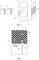
- a background 7 is provided which is Figure 3 is shown in detail.
- the background 7 is arranged with respect to the camera 6 and the measuring cuvette 2 such that the measuring cuvette 2 is located between the camera 6 and the background 7.
- An image recorded by the camera 6 thus comprises a representation of the measuring cuvette 2 and the background 7 behind the at least partially transparent measuring cuvette 2.
- the background 7 is designed such that it offers a contrast for drop detection on the one hand and reference colors for detecting the color change on the other hand.
- the background 7 has black and white areas 16 in a predetermined pattern, for example a checkerboard pattern as in Figure 3
- the predetermined pattern may be as shown in Figure 2 indicated, a full-surface white color with black rectangles that are arranged at a regular distance from each other.
- the predetermined pattern is a regular pattern, so that, for example, a honeycomb pattern with regularly arranged hexagons can also be used.
- the pattern can be an irregular, mosaic-like pattern. It is also preferred that black areas only border white areas. If necessary, individual areas 16 can also be formed in shades of gray or other colors.
- the side length of the rectangular surfaces 16 is preferably a maximum of half the width or diameter of a reagent droplet 15.
- the width or diameter of the reagent droplet 15 is usually determined by the shape of the reagent inlet 12.
- the average height or average width of the surfaces 16 is preferably a maximum of half the width or diameter of a reagent droplet 15.
- the pattern is depicted at least in that area of the background 7 which is located between the reagent inlet 12 and the sample liquid 5 in the recorded image.
- the pattern ie the shape of the surfaces and their colors, is preferably stored in advance in the evaluation unit 8.
- dripping reagent droplets 15 are particularly easy to recognize in the image recorded by the camera 6, in particular when at least two surfaces 16 are at least partially within the image of a reagent droplet 15, thereby achieving the contrast of the background 7.
- three reference color points 17 are also shown on the background, of which at least one is red, one is green and one is blue. This enables the evaluation unit 8 to determine a reference for the entire color range from an image recorded by the camera 6, which can be determined from the three primary colors red, green and blue, as is generally known to those skilled in the art.
- the position of the camera 6 can be calibrated using the reference color points 17 if it was not installed precisely, and on the other hand, color tolerances of the camera 6 and the LEDs described in more detail below that illuminate the measuring cuvette 2 can be compensated.
- the reference color points 17 can be depicted at any position on the background 7, provided that they are in the image area of the camera 6.
- the reference color points 17 can have any shape.
- the areas of the aforementioned pattern can also serve as shaping elements of the reference color points 17, as is the case in the example of the Figure 3 with three reference color points 17 in a checkerboard pattern.
- the position and the color value of the reference color points 17 are stored in advance in the evaluation unit 8.
- the background 7 can, for example, comprise a vertical stripe 18, which is preferably colored, in particular red, for easier recognition by the evaluation unit 8 and thus stands out from the pattern.
- the vertical stripe 18 is shown on the background 7 in such a way that it is at least partially located in the sample water 5 in the image. In the horizontal direction, the vertical stripe 18 is arranged off-center in relation to the measuring cuvette 2 in the image recorded by the camera. Due to the refraction of light, the vertical stripe 18 is shown offset below the water surface. Water has the physical property that a higher salt content brings with it a higher optical density and thus a stronger refraction of light, which leads to a higher offset of the vertical stripe 18. This allows the salinity of the sample water 5 to be determined.
- a magnifying glass 19 can be attached on, in front of or behind the measuring cuvette 2 in order to better recognize the deviation.
- the magnifying glass 19 has, for example, a 10x magnification and is positioned in such a way that a salt content of 3.5% can be recognized more precisely. If the strip 18 is not visible in the image section magnified by the magnifying glass 19, it can be concluded that the salt content of the sample water 5 deviates too much from the salt content under consideration, in this example 3.5%, whereby the evaluation unit 8 can issue a corresponding message.
- the function for determining the salinity can be implemented as follows, for example. Initially, a "region of interest" can be set in an area that is below the water surface and within the measuring chain 2. Using “object find", the preferred red line 18 can be searched for and the salinity can be determined based on its position. If a magnifying glass 19 is available, in a second step the "region of interest" can be set in the area of the magnifying glass 19 in order to determine an even more precise position of the strip 18.
- the background 7 can also have an element depicted on it for this purpose, namely at least one horizontal stripe 20, preferably at least one horizontal green stripe. If the horizontal stripe 20 is below the water level, it is distorted by the refraction of light.
- the horizontal stripe 20 can also be arranged off-center with respect to the measuring cuvette 2 in the image recorded by the camera.
- the horizontal stripe 20 is usually used to check the plausibility of the filling quantity, i.e. is used in addition to the method described above. In other embodiments, the method for determining the filling quantity could also be carried out using only the horizontal stripe 20. Preferably, more than one horizontal stripe 20 can also be used.
- the horizontal stripe(s) are typically located at a height corresponding to a predetermined filling quantity, for example 2 ml, 5 ml, 10 ml or 15 ml, and/or just below, e.g. 0.1 ml below, and/or just above, e.g. 0.1 ml above.
- the vertical stripe 18 and the horizontal stripe 20 can be depicted on the background 7.
- these stripes 18, 20 can also be printed directly on the measuring cuvette 2.
- the background 7 is a flat or curved image surface, for example made of cardboard or plastic.
- the background 7 could be printed directly on the measuring cuvette 2.
- the background 7 is preferably opaque behind the entire Area of the measuring cuvette 2 in the excluded image.
- the stripes 18, 20 could also be applied to an additional image area which is located in front of the image area with the pattern and the reference color points 17.
- a temperature probe and/or a pH probe can be provided, each of which is connected to the pipetting robot 1 and can each be located on a hose inserted into the aquarium, via which the sample water 5 is transferred to the measuring cuvette 2.
- the pH value can also be measured using the pH probe without a suitable reagent 10.
- alkalinity can be determined using a reagent 10 and the pH value can be determined using the pH probe at the same time.
- the pH probe should be calibrated regularly so that the pipetting robot 1 can measure the pH value using a reagent 10 and calibrate the pH probe based on this measured value.
- an outlet opening 21 Through which the sample water 5 in the measuring cuvette 2 can be discharged from the measuring cuvette 2 in order to empty it.
- a dosing pump provided underneath the measuring cuvette 2 can be used for this purpose.
- the emptying process is carried out, for example, after a measurement process to determine the aforementioned property or after an error message.
- An error message can be issued, for example, by an acceleration sensor and/or the inclination sensor after detecting an inclination or an impact of the pipetting robot 1. Alternatively or additionally, such an error message could also invalidate a measurement.
- the measuring cuvette 2 can be rinsed with osmotic water, which is let into the measuring cuvette 2 via an osmosis water inlet 22 on the top of the measuring cuvette 2. This allows residues to be removed from the measuring cuvette 2, which means that good measurement values can also be achieved for the next measurement.
- the function of detecting the water level described above can also be used for this in order to detect whether the correct amount of osmosis water is being pumped into the measuring cuvette 2.
- the measuring cuvette 2 is usually located in an opaque chamber which is illuminated by at least one lamp 23, preferably at least one LED lamp. This enables a homogeneous and constant illumination of the measuring cuvette 2 can be achieved.
- the lamp 23 is preferably installed next to the measuring cuvette 2. Alternatively or additionally, the lamp 23 can also be arranged above or below the measuring cuvette 2. Due to the refraction of light on the water surface, this then comes out clearer.
- the color depends not only on the color of the sample water 5 mixed with the reagent 10, but also on the color spectrum of the illuminating lamp 23. It has been found that it is more efficient and more cost-effective for the present purposes to use at least two LED lamps.
- a first LED lamp can be used that has intensity peaks in the range of 450 nm and 650 nm, and a second LED lamp that has an intensity peak in the range of 500 nm.
- These LED lamps 23 are preferably positioned at a 90° angle to the camera 6. Since reflections can occur in the measuring chamber, the color tone of the sample water 5 may look different depending on the position in the image. To determine the color value, color tones that are preferably located within a "region of interest" can therefore be averaged if a corresponding implementation is carried out in OpenCV.
- the reagents 10 are transferred from the pump 4 into the measuring cuvette 2.
- the sample water 5 can in turn be transferred from the aquarium into the measuring cuvette using its own pump. Osmosis water can be pumped into the measuring cuvette 2 using another pump.
- the measuring cuvette 2 can be emptied using the aforementioned dosing pump and the air bubbles for mixing the contents of the measuring cuvette 2 can be generated.
- the pipetting robot 1 can thus comprise four pumps, for example. In other embodiments, the number of pumps can also be reduced, for example if suitable connections or valves are provided.
- the pumps can also be designed as positive displacement pumps, as shown below with reference to the Figures 4 and 5 described.
- Several pump heads 24 are shown therein, with each pump head 24 being assigned to a reagent container 3.
- the pump heads 24 could each have their own pump motor 25, but in the preferred embodiment shown, the several pump heads 24 each share a common pump motor 25.
- the pump motor 25, e.g. a stepper motor, is slidably mounted on a linear guide 26 so that it can be selectively connected to one of the pump heads 24.
- the pump heads 24 have, for example, a hose with a hose inlet 27 and a hose outlet 28, wherein the hose inlet 27 is guided into the respective reagent container 3. Furthermore, the pump head 24 can have an eccentric (not shown in more detail) which acts on the hose and thereby conveys fluid from the hose inlet 27 to the hose outlet 28 when it is rotated about a rotation axis A by the pump motor 25.
- the pump motor 25 has a rotatable coupling unit 29, which has, for example, a rectangular or non-circular cross-section normal to the axis of rotation A.
- the pump head 24 has a counter-equivalent receptacle 30, which in the embodiment of Figure 4 is formed by two cuboids, between which the coupling unit 29 of the pump motor 25 can be inserted. If the pump motor 25 is now moved to the pump head 24 by means of the guide 26, the coupling unit 29 enters the holder 30. If the coupling unit 29 is now rotated about the rotation axis A, the holder 30 also rotates about the rotation axis A. In this way, the eccentric can rotate and liquid can be pumped.
- Figure 5 shows that the cuboids can also be replaced by two or more extruded triangles, ie three-sided prisms, arranged around the rotation axis A.
- the angle of attack between the coupling unit 29 and the holder 30 must be chosen less precisely in order to couple the pump motor 25 to the respective pump head 24.
- the pump heads 24 can be provided not only for the reagent containers 3, but also for introducing sample water 5 or rinsing water into the measuring cuvette 2 and/or for dosing other liquids.
- two or more pump motors 25 can be used on different guides 26 or alternatively on the same guide 26, wherein the pump motors 25 can preferably each be coupled to a different set of pump heads 24.
- the pipetting robot 1 could comprise twenty pump heads 24 and two pump motors 25, each with its own guide 26, wherein one of the pump motors 25 can be coupled to ten pump heads 24 and the other of the pump motors 25 to the ten other pump heads 24.
- the pipetting robot 1 can have a plastic ring 31 on which several vessels 32 are formed, for example at least two, at least ten or at least fifty.
- a powder is stored in each of the vessels 32, by means of which a color change representative of the predetermined property can be brought about in the sample water.
- the powder is usually used in combination with the liquid reagents mentioned in order to measure certain measured values (eg the calcium or nitrate concentration). For example, calcium requires two liquid reagents and one that consists of powder.
- the vessels 32 are sealed on a first side, usually the top, with a film 33, which consists for example of aluminum, polyethylene or polyvinyl alcohol. This ensures that the powder remains dry until use.
- a film 33 which consists for example of aluminum, polyethylene or polyvinyl alcohol.
- the needle 34 can for example be arranged on a solenoid valve so that the puncturing movement of the needle 34 is carried out by the solenoid valve.
- the needle 34 is located at the point S1, ie by controlling the solenoid valve the film 33 of the vessel 32 is pierced at the point S1.
- the plastic ring 31 is then rotated by a stepping motor 35 so that the vessel 32 with the pierced foil 33 is moved to a second location S2, at which a liquid, for example sample water or osmosis water, is filled into the vessel 32 through the pierced foil 33.
- a liquid for example sample water or osmosis water
- the vessel 32 with the pierced film 33 and dissolved powder is then moved to a third location S3 in order to transfer the dissolved powder into the measuring cuvette 2.
- the third location S3 can, for example, be located directly above the measuring cuvette 2 or above a slide or a hose which transfers the dissolved powder to the measuring cuvette 2.
- a second film which forms the underside of the vessel 32 can, for example, be pierced.
- the vessel 32 comprises, for example, an annular plastic wall which is formed as one piece on the plastic ring 31 and two films which close the top and bottom of the annular plastic wall.
- the second film can be pierced by means of a further needle 36 which can, for example, pierce through the vessel 32 from above in order to release the powder dissolved in the liquid.
- the second film could be water-soluble and consist of, for example, water-soluble polyvinyl alcohol (PVA).
- PVA water-soluble polyvinyl alcohol
- the second film breaks of its own accord after the liquid has been poured in and the powder dissolved in the liquid falls into the measuring cuvette 2.
- the second point S2 preferably coincides with the third point S3.
- the camera 6 mentioned can in turn be used to detect when the liquid with dissolved powder drips into the measuring cuvette 2 in order to continue with the next process step.
- the mixing process can optionally be further stimulated by moving the plastic ring 31, for example by turning it back and forth several times using the stepper motor. The movement on the water-soluble film has the same effect as stirring and causes it to dissolve more quickly.
- the embodiments of introducing the dissolved powder into the measuring cuvette 2 are not limited exclusively to the aforementioned rotatable plastic ring, but in general it could also simply be a vessel that is tilted to pour a powder dissolved in a liquid into the measuring cuvette.
- Alternatives to opening the foil are also conceivable, for example peeling off the foil.
- the liquid reagents described above could be produced by previously dissolving solid powder using a liquid.
Landscapes
- Physics & Mathematics (AREA)
- Chemical & Material Sciences (AREA)
- Health & Medical Sciences (AREA)
- Life Sciences & Earth Sciences (AREA)
- Immunology (AREA)
- General Health & Medical Sciences (AREA)
- General Physics & Mathematics (AREA)
- Analytical Chemistry (AREA)
- Pathology (AREA)
- Biochemistry (AREA)
- Spectroscopy & Molecular Physics (AREA)
- Engineering & Computer Science (AREA)
- Food Science & Technology (AREA)
- Mathematical Physics (AREA)
- Theoretical Computer Science (AREA)
- Medicinal Chemistry (AREA)
- Chemical Kinetics & Catalysis (AREA)
- Plasma & Fusion (AREA)
- Automatic Analysis And Handling Materials Therefor (AREA)
Claims (15)
- Robot de pipetage (1) pour la détermination d'au moins une propriété prédéterminée d'eau d'échantillon (5), en particulier d'eau d'aquarium, comprenant- une cuvette de mesure (2) destinée à recevoir l'eau d'échantillonnage (5),- au moins un récipient de réactif (3) pour recevoir un réactif liquide (10), au moyen duquel réactif (10) un changement de couleur représentatif de la propriété prédéterminée peut être provoqué dans l'eau d'échantillon (5),- une pompe (4) pour transférer le réactif (10) du réservoir de réactif (3) dans la cuvette de mesure (2) via une entrée de réactif (12) sur un côté supérieur de la cuvette de mesure (2), permettant ainsi au réactif (10) de s'égoutter dans la cuvette de mesure (2), et- une caméra (6) pour enregistrer des images de la cuvette de mesure (2) et de l'eau d'échantillon (5) se trouvant dans la cuvette de mesure (2),- un fond (7) qui est disposé sur le côté de la cuvette de mesure (2) opposé à la caméra (6) et qui se trouve dans le champ de vision de la caméra (6), des surfaces (16) d'au moins deux couleurs différentes étant représentées sur le fond (7) pour la création de contraste dans un modèle prédéterminé, le modèle étant de préférence un modèle en damier avec des surfaces noires et blanches (16), et au moins trois points de couleur de référence (17) étant représentés sur le fond (7) pour la création de référence de couleur, dont au moins un est rouge, un vert et un bleu, et- une unité d'évaluation (8) qui est conçue pour déterminer, à l'aide des images enregistrées par la caméra (6), la quantité de remplissage de l'eau d'échantillon (5) dans la cuvette de mesure (2), pour compter le nombre de gouttelettes de réactif (15) tombées dans la cuvette de mesure (2) et pour déterminer, à partir du nombre compté de gouttelettes de réactif (15) en combinaison avec le changement de couleur de l'eau d'échantillon (5) déterminé à partir des images, l'au moins une propriété prédéterminée de l'eau d'échantillon (5).
- Robot de pipetage (1) selon la revendication 1, dans lequel l'entrée de réactif (12) est adaptée pour distribuer des gouttelettes de réactif (15) ayant une taille de gouttelette prédéterminée, et dans lequel lesdites surfaces (16) ont une hauteur moyenne et/ou une longueur moyenne qui correspond au maximum à la moitié de la taille de gouttelette.
- Robot de pipetage (1) selon la revendication 1 ou 2, dans lequel la pompe (4) comprend au moins une tête de pompe sans moteur (24) et un moteur de pompe (25) pouvant être couplé à la tête de pompe sans moteur (24), dans lequel le robot de pipetage (1) comprend de préférence au moins deux récipients de réactifs (3) et une tête de pompe sans moteur (24) propre pour chacun des au moins deux récipients de réactifs (3), et le moteur de pompe (25) étant monté sur un guide (26) et pouvant être couplé sélectivement aux têtes de pompe (24) des au moins deux récipients à réactifs (3) par déplacement sur le guide (26), le moteur de pompe (25) comprenant de préférence une unité de couplage (29) pouvant tourner autour d'un axe de rotation (A), qui peut être introduite dans un logement (30) opposé de la tête de pompe (24) sans moteur pour le couplage avec la tête de pompe (24) sans moteur, le logement (30) de la tête de pompe (24) présentant de préférence au moins deux broches disposées symétriquement autour d'un axe de rotation (A), qui ont en section transversale la forme d'un triangle ou d'un secteur circulaire.
- Robot de pipetage (1) selon l'une des revendications 1 à 3, dans lequel le robot de pipetage (1) présente au moins deux, de préférence au moins dix, récipients de réactifs (3) qui sont respectivement en liaison avec la pompe (4) et la cuvette de mesure (2), dans lequel les récipients de réactifs (3) comprennent respectivement une vanne commandable, de préférence une électrovanne (14), pour la liaison sélective à la pompe (4) et/ou à la cuvette de mesure (2), et/ou dans lequel le ou les récipients de réactifs (3) peuvent être montés de manière amovible dans le robot de pipetage (1).
- Robot de pipetage (1) selon l'une des revendications 1 à 4, dans lequel le robot de pipetage (1) est relié à une source de l'eau d'échantillon et est conçu pour pomper de l'eau d'échantillon (5) dans la cuvette de mesure (2) jusqu'à ce que l'unité d'évaluation (8) reconnaisse une quantité de remplissage souhaitée dans la cuvette de mesure (2) à l'aide des images enregistrées par la caméra (6), l'unité d'évaluation (8) étant de préférence conçue pour déterminer l'obtention de la quantité de remplissage souhaitée par comparaison avec une position de référence enregistrée dans l'unité d'évaluation (8) dans les images prises par la caméra (6), la cuvette de mesure (2) présentant de manière particulièrement préférée une entrée d'eau d'échantillon transparente (9) pour l'amenée de l'eau d'échantillon (5) et le robot de pipetage (1) étant conçu pour effectuer un processus de pompage de l'eau d'échantillon (5) dans la cuvette de mesure (2) à une première vitesse de pompage d'eau d'échantillon aussi longtemps, jusqu'à ce que l'unité d'évaluation (8) détecte la présence de l'eau d'échantillon (5) dans l'entrée d'eau d'échantillon (12), et à effectuer le processus de pompage à une deuxième vitesse de pompage d'eau d'échantillon qui est inférieure à la première vitesse de pompage d'eau d'échantillon jusqu'à ce que l'unité d'évaluation (8) détecte de l'eau d'échantillon (5) à la position de référence.
- Robot de pipetage (1) selon l'une des revendications 1 à 5, dans lequel l'entrée de réactif (12) est transparente et dans lequel la pompe (4) est configurée pour effectuer une opération de pompage du réactif (10) à une première vitesse de pompage du réactif jusqu'à ce que l'unité d'évaluation (8) détecte la présence du réactif dans l'entrée de réactif, et à effectuer le processus de pompage à une deuxième vitesse de pompage du réactif, qui est inférieure à la première vitesse de pompage du réactif, jusqu'à ce que l'unité d'évaluation (8) ait compté un nombre prédéterminé de gouttelettes de réactif (15) ou détecté un changement de couleur dans l'eau d'échantillonnage (5).
- Robot de pipetage (1) selon l'une des revendications 1 à 6, dans lequel l'unité d'évaluation (8) est conçue pour compter les gouttelettes de réactif (15) s'égouttant de l'entrée de réactif (12) dans la cuvette de mesure (2) et pour arrêter la pompe (4) dès qu'un nombre prédéterminé de gouttelettes de réactif (15) ou un changement de couleur prédéterminé de l'eau d'échantillonnage (5) a été détecté.
- Robot de pipetage (1) selon l'une des revendications 1 à 7, dans lequel le fond (7) ou la cuvette de mesure (2) présente une bande verticale (18), de préférence une bande rouge verticale, pour déterminer une teneur en sel, dans lequel la cuvette de mesure (2) présente en outre de préférence une loupe (19) et la caméra (6), la loupe (19) et la bande verticale (18) sont positionnées de telle sorte, que la bande verticale (18) est représentée agrandie sur les images prises par la caméra (6) pour une teneur en sel de 3,5% dans l'eau d'échantillonnage (5), et/ou dans lequel le fond (7) ou la cuvette de mesure (2) présente au moins une bande horizontale (20), de préférence au moins une bande verte horizontale, pour la plausibilisation d'une quantité de remplissage.
- Robot de pipetage (1) selon l'une quelconque des revendications 1 à 8, dans lequel la cuvette de mesure (2) présente sur sa face inférieure une ouverture de sortie (21) pour vider la cuvette de mesure (2), le robot de pipetage (1) étant de préférence conçu pour laisser entrer au moins une bulle d'air par ladite ouverture de sortie (21) pour mélanger l'eau d'échantillon (5) et le réactif (10) qui a été égoutté.
- Robot de pipetage (1) selon l'une des revendications 1 à 9, dans lequel la propriété prédéterminée est une valeur de pH, le réactif (10) étant choisi de manière à provoquer un changement de couleur de l'eau d'échantillon (5) en fonction de la valeur de pH, l'unité d'évaluation (8) étant conçue pour cela, déterminer la valeur du pH de l'eau d'échantillon (5) en fonction du changement de couleur, une sonde de mesure de la valeur du pH étant en outre reliée au robot de pipetage (1) et l'unité d'évaluation (8) étant conçue pour calibrer la sonde au moyen de la valeur du pH qui a été déterminée par l'unité d'évaluation (8) par l'intermédiaire du changement de couleur.
- Robot de pipetage (1) selon l'une des revendications 1 à 10, dans lequel le robot de pipetage (1) comprend une chambre opaque dans laquelle se trouve la cuvette de mesure (2), dans lequel au moins une lampe (23), de préférence une lampe LED, est disposée dans la chambre pour éclairer la cuvette de mesure (2), et dans lequel la lampe (23) se trouve de préférence à côté de la cuvette de mesure (2).
- Robot de pipetage (1) selon l'une des revendications 1 à 11, comprenant un capteur d'accélération et/ou un capteur d'inclinaison, l'unité d'évaluation (8) étant conçue pour invalider une mesure de la propriété prédéterminée lorsque le capteur d'accélération et/ou le capteur d'inclinaison indiquent une inclinaison ou un choc du robot de pipetage (1).
- Robot de pipetage (1) selon l'une des revendications 1 à 12, comprenant en outre un récipient (32) dans lequel est stockée une poudre, au moyen de laquelle poudre un changement de couleur représentatif de la propriété prédéterminée peut être provoqué dans l'eau échantillon (5), le récipient (32) étant fermé au moins sur un premier côté, de préférence sur le côté supérieur, au moyen d'un premier film (33), le robot de pipetage (1) comprenant en outre une aiguille (34) et étant conçu pour percer le premier film (33) au moyen de l'aiguille (34), pour remplir le récipient (32) d'un liquide destiné à dissoudre la poudre et pour transférer la poudre dissoute dans le liquide dans la cuvette de mesure (2), le récipient (32) étant de préférence également fermé sur un deuxième côté, de préférence sur le côté inférieur, au moyen d'un deuxième film à travers lequel la poudre dissoute dans le liquide peut être transférée dans la cuvette de mesure (2), le robot de pipetage (1) comprenant de préférence un anneau en plastique (31) pouvant être inséré de manière modulaire en option dans le robot de pipetage (1) et au moins deux des récipients (32) mentionnés, dans lesquels de la poudre est respectivement stockée, les récipients (32) étant répartis autour de la périphérie de l'anneau en plastique (31) et le robot de pipetage (1) comprenant un moteur pas à pas (35) pour faire tourner l'anneau en plastique (31), au moyen duquel les récipients peuvent être tournés sélectivement vers l'aiguille (34), vers le point d'amenée du liquide et/ou vers le point de transfert vers la cuvette de mesure (2).
- Utilisation du robot de pipetage (1) selon l'une des revendications 1 à 13 pour déterminer une propriété prédéterminée de l'eau d'échantillon (5), l'eau d'échantillon (5) étant de l'eau d'aquarium et la propriété prédéterminée étant de préférence une alcalinité, une dureté du calcium, une dureté du magnésium, une valeur de phosphate, une valeur de nitrate et/ou une valeur de pH.
- Procédé de détermination d'une propriété prédéterminée d'une eau d'échantillon (5) au moyen d'un robot de pipetage (1) selon l'une quelconque des revendications 1 à 13, comprenant les étapes consistant à :- Remplir l'eau d'échantillon (5) dans la cuvette de mesure (2),- Transférer le réactif (10) du récipient de réactif (3) dans la cuvette de mesure (3) au moyen de la pompe (4),- Prendre d'images de la cuvette de mesure (2) par la caméra (6),- Compter des gouttelettes de réactif (15) qui sont introduites goutte à goutte dans la cuvette de mesure (2) via l'entrée de réactif (12), et déterminer un changement de couleur de l'eau d'échantillon (5) par l'unité d'évaluation (8) à l'aide des images enregistrées par la caméra (6), et- Déterminer la propriété prédéterminée à l'aide des gouttelettes de réactif (15) comptées et/ou du changement de couleur déterminé.
Applications Claiming Priority (2)
| Application Number | Priority Date | Filing Date | Title |
|---|---|---|---|
| AT603602020 | 2020-12-04 | ||
| PCT/AT2021/060461 WO2022115895A1 (fr) | 2020-12-04 | 2021-12-03 | Robot de pipetage pour déterminer au moins une propriété de l'eau |
Publications (3)
| Publication Number | Publication Date |
|---|---|
| EP4256306A1 EP4256306A1 (fr) | 2023-10-11 |
| EP4256306B1 true EP4256306B1 (fr) | 2025-02-26 |
| EP4256306C0 EP4256306C0 (fr) | 2025-02-26 |
Family
ID=79259210
Family Applications (1)
| Application Number | Title | Priority Date | Filing Date |
|---|---|---|---|
| EP21836317.4A Active EP4256306B1 (fr) | 2020-12-04 | 2021-12-03 | Robot de pipettage pour la détermination d'au moins une caractéristique de l'eau |
Country Status (2)
| Country | Link |
|---|---|
| EP (1) | EP4256306B1 (fr) |
| WO (1) | WO2022115895A1 (fr) |
Families Citing this family (1)
| Publication number | Priority date | Publication date | Assignee | Title |
|---|---|---|---|---|
| CN121805157A (zh) * | 2026-03-06 | 2026-04-07 | 甘肃中检微明环境科技有限公司 | 一种污水处理用水质检测设备 |
Family Cites Families (11)
| Publication number | Priority date | Publication date | Assignee | Title |
|---|---|---|---|---|
| JP2000121411A (ja) | 1998-10-16 | 2000-04-28 | Hitachi Ltd | 水位計測方法、および、水位計測設備 |
| AUPS229802A0 (en) | 2002-05-07 | 2002-06-13 | Bremauer, Ben | Apparatus for mixing and/or testing small volumes of fluids |
| GB0422358D0 (en) | 2004-10-08 | 2004-11-10 | Rts Thurnall Plc | Determination of the boundaries between fractions and extraction of selected fractions in a fractional sample |
| US7794660B2 (en) | 2006-01-13 | 2010-09-14 | Hf Scientific, Inc. | Fluid content monitor |
| DE202008006338U1 (de) | 2008-05-12 | 2009-03-26 | Matthias, Torsten, Dr. | Analysegerät |
| DE102008050092A1 (de) | 2008-10-06 | 2010-04-08 | Hach Lange Gmbh | Mobile Wasser-Analyseanordnung |
| EP2802863B1 (fr) * | 2012-01-09 | 2024-01-03 | Stevanato Group Denmark A/S | Inspection automatique d'objets standard |
| US9689803B1 (en) * | 2016-04-20 | 2017-06-27 | Chroma Fish Corp. | Method and system for measuring a colorimetric characteristic of a sample and calibration of same |
| TWI693888B (zh) * | 2018-05-08 | 2020-05-21 | 國立中正大學 | 自動水質調節系統及方法 |
| CN109839490A (zh) | 2019-02-28 | 2019-06-04 | 浙江索奥环境技术有限公司 | 水质监测质量控制和多通道加标回收运维机器人 |
| KR102150683B1 (ko) | 2020-05-28 | 2020-09-02 | 한국생산기술연구원 | 다종의 수질 측정 자동화 시스템 및 그의 자동화 방법 |
-
2021
- 2021-12-03 EP EP21836317.4A patent/EP4256306B1/fr active Active
- 2021-12-03 WO PCT/AT2021/060461 patent/WO2022115895A1/fr not_active Ceased
Also Published As
| Publication number | Publication date |
|---|---|
| WO2022115895A1 (fr) | 2022-06-09 |
| EP4256306C0 (fr) | 2025-02-26 |
| EP4256306A1 (fr) | 2023-10-11 |
Similar Documents
| Publication | Publication Date | Title |
|---|---|---|
| DE69725737T2 (de) | Abgabevorrichtung und deren bedienungsverfahren | |
| EP3716823B2 (fr) | Logement de cartouche, système de cartouche, machine de préparation de boissons et procédé de préparation d'une boisson | |
| DE1773226C3 (fr) | ||
| DE4310808C2 (de) | System zur Dosierung von Flüssigkeiten | |
| DE10013242B4 (de) | Chemisches Analysegerät | |
| EP0619476A1 (fr) | Dispositif pour la détection d'un interface fluidique dans un tube de mesure transparent | |
| DE3014250A1 (de) | Automatisches analysiergeraet fuer fluessigproben | |
| DE69327182T2 (de) | Gerät und Verfahren zur Untersuchung von Teilchen in einem Fluid | |
| EP2369328B1 (fr) | Procédé et dispositif pour examiner des impuretés dans des récipients rempli | |
| EP2251678A2 (fr) | Dispositif d'inspection pour la reconnaissance de gaufrages et/ou d'étiquettes sur des récipients transparents, notamment des bouteilles de boisson | |
| EP2057459A1 (fr) | Procédé et dispositif de détection de cellules de phytoplancton vivantes dans l'eau | |
| EP3047232B1 (fr) | Procédé et dispositif de détermination de la géométrie d'un contenant destiné à l'emballage d'une substance liquide | |
| DE1816226C3 (de) | Reaktionsbehälter | |
| DE102012016342A1 (de) | Behälterinneninspektion von unten durch den Boden hindurch | |
| EP3839476A1 (fr) | Dispositif et procédé de détermination d'une position et/ou d'une extension d'une goutte | |
| DE102019120414A1 (de) | Verfahren zur Dosierung einer Flüssigkeitsmenge mit einer Schlauchpumpe | |
| DE1816227C3 (de) | Reaktionsbehälter | |
| EP4256306A1 (fr) | Robot de pipetage pour déterminer au moins une propriété de l'eau | |
| DE1816225A1 (de) | Reaktionsbehaelter | |
| EP2652479A1 (fr) | Système de mesure pour l'évaluation optique quantitative d'une réaction chimique | |
| DE2912270A1 (de) | Geraet zur bestimmung einer teilchengroesse | |
| DE3800667C2 (fr) | ||
| DE102010013335A1 (de) | Vorrichtung und Verfahren zur Kontrolle des Inhalts Medikamente enthaltender Packungseinheiten | |
| EP3971131B1 (fr) | Distributeur de boissons | |
| DE60217469T2 (de) | Vorrichtung und verfahren zum verarbeiten und testen einer biologischen probe |
Legal Events
| Date | Code | Title | Description |
|---|---|---|---|
| STAA | Information on the status of an ep patent application or granted ep patent |
Free format text: STATUS: UNKNOWN |
|
| STAA | Information on the status of an ep patent application or granted ep patent |
Free format text: STATUS: THE INTERNATIONAL PUBLICATION HAS BEEN MADE |
|
| PUAI | Public reference made under article 153(3) epc to a published international application that has entered the european phase |
Free format text: ORIGINAL CODE: 0009012 |
|
| STAA | Information on the status of an ep patent application or granted ep patent |
Free format text: STATUS: REQUEST FOR EXAMINATION WAS MADE |
|
| 17P | Request for examination filed |
Effective date: 20230620 |
|
| AK | Designated contracting states |
Kind code of ref document: A1 Designated state(s): AL AT BE BG CH CY CZ DE DK EE ES FI FR GB GR HR HU IE IS IT LI LT LU LV MC MK MT NL NO PL PT RO RS SE SI SK SM TR |
|
| DAV | Request for validation of the european patent (deleted) | ||
| DAX | Request for extension of the european patent (deleted) | ||
| GRAP | Despatch of communication of intention to grant a patent |
Free format text: ORIGINAL CODE: EPIDOSNIGR1 |
|
| STAA | Information on the status of an ep patent application or granted ep patent |
Free format text: STATUS: GRANT OF PATENT IS INTENDED |
|
| RIC1 | Information provided on ipc code assigned before grant |
Ipc: G01N 35/04 20060101ALN20240911BHEP Ipc: G01N 21/17 20060101ALN20240911BHEP Ipc: G01N 21/80 20060101ALN20240911BHEP Ipc: G01N 21/41 20060101ALN20240911BHEP Ipc: G01N 21/11 20060101ALN20240911BHEP Ipc: G01N 35/10 20060101ALI20240911BHEP Ipc: G01N 33/18 20060101ALI20240911BHEP Ipc: G01N 21/78 20060101ALI20240911BHEP Ipc: G01N 21/29 20060101ALI20240911BHEP Ipc: G01N 21/27 20060101ALI20240911BHEP Ipc: G01N 21/25 20060101AFI20240911BHEP |
|
| INTG | Intention to grant announced |
Effective date: 20240924 |
|
| GRAS | Grant fee paid |
Free format text: ORIGINAL CODE: EPIDOSNIGR3 |
|
| GRAA | (expected) grant |
Free format text: ORIGINAL CODE: 0009210 |
|
| STAA | Information on the status of an ep patent application or granted ep patent |
Free format text: STATUS: THE PATENT HAS BEEN GRANTED |
|
| RAP3 | Party data changed (applicant data changed or rights of an application transferred) |
Owner name: KOFLER GMBH |
|
| AK | Designated contracting states |
Kind code of ref document: B1 Designated state(s): AL AT BE BG CH CY CZ DE DK EE ES FI FR GB GR HR HU IE IS IT LI LT LU LV MC MK MT NL NO PL PT RO RS SE SI SK SM TR |
|
| REG | Reference to a national code |
Ref country code: GB Ref legal event code: FG4D Free format text: NOT ENGLISH |
|
| REG | Reference to a national code |
Ref country code: CH Ref legal event code: EP |
|
| REG | Reference to a national code |
Ref country code: DE Ref legal event code: R096 Ref document number: 502021006816 Country of ref document: DE |
|
| REG | Reference to a national code |
Ref country code: IE Ref legal event code: FG4D Free format text: LANGUAGE OF EP DOCUMENT: GERMAN |
|
| U01 | Request for unitary effect filed |
Effective date: 20250313 |
|
| U07 | Unitary effect registered |
Designated state(s): AT BE BG DE DK EE FI FR IT LT LU LV MT NL PT RO SE SI Effective date: 20250321 |
|
| PG25 | Lapsed in a contracting state [announced via postgrant information from national office to epo] |
Ref country code: RS Free format text: LAPSE BECAUSE OF FAILURE TO SUBMIT A TRANSLATION OF THE DESCRIPTION OR TO PAY THE FEE WITHIN THE PRESCRIBED TIME-LIMIT Effective date: 20250526 |
|
| PG25 | Lapsed in a contracting state [announced via postgrant information from national office to epo] |
Ref country code: PL Free format text: LAPSE BECAUSE OF FAILURE TO SUBMIT A TRANSLATION OF THE DESCRIPTION OR TO PAY THE FEE WITHIN THE PRESCRIBED TIME-LIMIT Effective date: 20250226 |
|
| PG25 | Lapsed in a contracting state [announced via postgrant information from national office to epo] |
Ref country code: ES Free format text: LAPSE BECAUSE OF FAILURE TO SUBMIT A TRANSLATION OF THE DESCRIPTION OR TO PAY THE FEE WITHIN THE PRESCRIBED TIME-LIMIT Effective date: 20250226 |
|
| PG25 | Lapsed in a contracting state [announced via postgrant information from national office to epo] |
Ref country code: IS Free format text: LAPSE BECAUSE OF FAILURE TO SUBMIT A TRANSLATION OF THE DESCRIPTION OR TO PAY THE FEE WITHIN THE PRESCRIBED TIME-LIMIT Effective date: 20250626 Ref country code: NO Free format text: LAPSE BECAUSE OF FAILURE TO SUBMIT A TRANSLATION OF THE DESCRIPTION OR TO PAY THE FEE WITHIN THE PRESCRIBED TIME-LIMIT Effective date: 20250526 |
|
| PG25 | Lapsed in a contracting state [announced via postgrant information from national office to epo] |
Ref country code: HR Free format text: LAPSE BECAUSE OF FAILURE TO SUBMIT A TRANSLATION OF THE DESCRIPTION OR TO PAY THE FEE WITHIN THE PRESCRIBED TIME-LIMIT Effective date: 20250226 |
|
| PG25 | Lapsed in a contracting state [announced via postgrant information from national office to epo] |
Ref country code: GR Free format text: LAPSE BECAUSE OF FAILURE TO SUBMIT A TRANSLATION OF THE DESCRIPTION OR TO PAY THE FEE WITHIN THE PRESCRIBED TIME-LIMIT Effective date: 20250527 |
|
| PG25 | Lapsed in a contracting state [announced via postgrant information from national office to epo] |
Ref country code: SM Free format text: LAPSE BECAUSE OF FAILURE TO SUBMIT A TRANSLATION OF THE DESCRIPTION OR TO PAY THE FEE WITHIN THE PRESCRIBED TIME-LIMIT Effective date: 20250226 |
|
| PG25 | Lapsed in a contracting state [announced via postgrant information from national office to epo] |
Ref country code: CZ Free format text: LAPSE BECAUSE OF FAILURE TO SUBMIT A TRANSLATION OF THE DESCRIPTION OR TO PAY THE FEE WITHIN THE PRESCRIBED TIME-LIMIT Effective date: 20250226 |
|
| PG25 | Lapsed in a contracting state [announced via postgrant information from national office to epo] |
Ref country code: SK Free format text: LAPSE BECAUSE OF FAILURE TO SUBMIT A TRANSLATION OF THE DESCRIPTION OR TO PAY THE FEE WITHIN THE PRESCRIBED TIME-LIMIT Effective date: 20250226 |
|
| PLBE | No opposition filed within time limit |
Free format text: ORIGINAL CODE: 0009261 |
|
| STAA | Information on the status of an ep patent application or granted ep patent |
Free format text: STATUS: NO OPPOSITION FILED WITHIN TIME LIMIT |
|
| 26N | No opposition filed |
Effective date: 20251127 |