EP4256376B1 - Fahrzeuganordnung mit einem radarsensor und einem lichtemittierenden signalmodul - Google Patents
Fahrzeuganordnung mit einem radarsensor und einem lichtemittierenden signalmodul Download PDFInfo
- Publication number
- EP4256376B1 EP4256376B1 EP21815473.0A EP21815473A EP4256376B1 EP 4256376 B1 EP4256376 B1 EP 4256376B1 EP 21815473 A EP21815473 A EP 21815473A EP 4256376 B1 EP4256376 B1 EP 4256376B1
- Authority
- EP
- European Patent Office
- Prior art keywords
- layer
- light module
- patterns
- vehicle assembly
- radar
- Prior art date
- Legal status (The legal status is an assumption and is not a legal conclusion. Google has not performed a legal analysis and makes no representation as to the accuracy of the status listed.)
- Active
Links
Images

Classifications
-
- G—PHYSICS
- G01—MEASURING; TESTING
- G01S—RADIO DIRECTION-FINDING; RADIO NAVIGATION; DETERMINING DISTANCE OR VELOCITY BY USE OF RADIO WAVES; LOCATING OR PRESENCE-DETECTING BY USE OF THE REFLECTION OR RERADIATION OF RADIO WAVES; ANALOGOUS ARRANGEMENTS USING OTHER WAVES
- G01S13/00—Systems using the reflection or reradiation of radio waves, e.g. radar systems; Analogous systems using reflection or reradiation of waves whose nature or wavelength is irrelevant or unspecified
- G01S13/88—Radar or analogous systems specially adapted for specific applications
- G01S13/93—Radar or analogous systems specially adapted for specific applications for anti-collision purposes
- G01S13/931—Radar or analogous systems specially adapted for specific applications for anti-collision purposes of land vehicles
-
- G—PHYSICS
- G01—MEASURING; TESTING
- G01S—RADIO DIRECTION-FINDING; RADIO NAVIGATION; DETERMINING DISTANCE OR VELOCITY BY USE OF RADIO WAVES; LOCATING OR PRESENCE-DETECTING BY USE OF THE REFLECTION OR RERADIATION OF RADIO WAVES; ANALOGOUS ARRANGEMENTS USING OTHER WAVES
- G01S7/00—Details of systems according to groups G01S13/00, G01S15/00, G01S17/00
- G01S7/02—Details of systems according to groups G01S13/00, G01S15/00, G01S17/00 of systems according to group G01S13/00
- G01S7/027—Constructional details of housings, e.g. form, type, material or ruggedness
-
- H—ELECTRICITY
- H01—ELECTRIC ELEMENTS
- H01Q—ANTENNAS, i.e. RADIO AERIALS
- H01Q1/00—Details of, or arrangements associated with, antennas
- H01Q1/27—Adaptation for use in or on movable bodies
- H01Q1/32—Adaptation for use in or on road or rail vehicles
- H01Q1/3208—Adaptation for use in or on road or rail vehicles characterised by the application wherein the antenna is used
- H01Q1/3233—Adaptation for use in or on road or rail vehicles characterised by the application wherein the antenna is used particular used as part of a sensor or in a security system, e.g. for automotive radar, navigation systems
-
- H—ELECTRICITY
- H01—ELECTRIC ELEMENTS
- H01Q—ANTENNAS, i.e. RADIO AERIALS
- H01Q1/00—Details of, or arrangements associated with, antennas
- H01Q1/27—Adaptation for use in or on movable bodies
- H01Q1/32—Adaptation for use in or on road or rail vehicles
- H01Q1/325—Adaptation for use in or on road or rail vehicles characterised by the location of the antenna on the vehicle
- H01Q1/3291—Adaptation for use in or on road or rail vehicles characterised by the location of the antenna on the vehicle mounted in or on other locations inside the vehicle or vehicle body
-
- H—ELECTRICITY
- H01—ELECTRIC ELEMENTS
- H01Q—ANTENNAS, i.e. RADIO AERIALS
- H01Q19/00—Combinations of primary active antenna elements and units with secondary devices, e.g. with quasi-optical devices, for giving the antenna a desired directional characteristic
- H01Q19/06—Combinations of primary active antenna elements and units with secondary devices, e.g. with quasi-optical devices, for giving the antenna a desired directional characteristic using refracting or diffracting devices, e.g. lens
-
- G—PHYSICS
- G01—MEASURING; TESTING
- G01S—RADIO DIRECTION-FINDING; RADIO NAVIGATION; DETERMINING DISTANCE OR VELOCITY BY USE OF RADIO WAVES; LOCATING OR PRESENCE-DETECTING BY USE OF THE REFLECTION OR RERADIATION OF RADIO WAVES; ANALOGOUS ARRANGEMENTS USING OTHER WAVES
- G01S13/00—Systems using the reflection or reradiation of radio waves, e.g. radar systems; Analogous systems using reflection or reradiation of waves whose nature or wavelength is irrelevant or unspecified
- G01S13/88—Radar or analogous systems specially adapted for specific applications
- G01S13/93—Radar or analogous systems specially adapted for specific applications for anti-collision purposes
- G01S13/931—Radar or analogous systems specially adapted for specific applications for anti-collision purposes of land vehicles
- G01S2013/9327—Sensor installation details
- G01S2013/93277—Sensor installation details in the lights
Definitions
- the present invention relates to a vehicle assembly for a vehicle. It finds a particular but non-limiting application in motor vehicles.
- Radar sensors are increasingly being used to detect an object in the external environment of a motor vehicle and estimate its angular position, and consequently perform automatic emergency braking, cruise control or blind spot detection functions. These radar sensors are traditionally mounted behind the bumper of the motor vehicle.
- a disadvantage of this state of the art is that integration behind the bumper reduces the performance of radar sensors due to the metallic paint layer applied to the bumper and due to the curved shape of said bumper. This results in a poor estimation of the angular position of an object.
- the document DE102011115829A1 discloses a radar and a light module performing a signaling function according to the prior art.
- the present invention aims to provide a vehicle assembly which makes it possible to solve the mentioned drawback.
- the vehicle assembly may further comprise one or more additional characteristics taken alone or in all technically possible combinations, among the following.
- said radar sensor is a millimeter wave or hyperfrequency or microwave radar sensor.
- said radar waves are emitted on a frequency band between 100 MHz and 5 GHz.
- said pattern repetition period is less than one tenth of said wavelength of the radar waves.
- said patterns are cylindrical, or rectangular, or pyramidal, or cubic prisms, or portions of tori.
- a pattern comprises dimensions less than 0.4 mm.
- said total thickness is formed by the height of said patterns and by the thickness of said underlayer.
- the total thickness is equal to said wavelength divided by twice the equivalent refractive index.
- the total thickness is defined with an angle of incidence equal to arctan(d1/(2e4)), with e4 the distance between said radar sensor and said light module and d1 the distance between a transmitting antenna and receiving antennas of said radar sensor.
- said light module further comprises a reflective layer and the total thickness of said light module is equal to m times a wavelength of said range, all divided by twice the equivalent refractive index of said sub-layer, of said pattern layer and of said reflective layer times the cosine of a refracted angle corresponding to an angle of incidence of the radar waves, with m an integer.
- the equivalent refractive index is calculated for an angle of incidence of the radar waves equal to the center of a field of vision of said radar sensor.
- said light module is a daytime running light module, or a turn signal, or a reflector, or a high-mounted brake light.
- a light module arranged opposite a radar sensor configured to emit radar waves over a range of wavelengths, said light module being configured to perform a signaling function and comprising a sub-layer and a pattern layer, said pattern layer forming a sub-wavelength structured dielectric element with a pattern repetition period which is less than a quarter of a wavelength of said range, and characterized in that the total thickness of said light module is equal to m times said wavelength all divided by twice the equivalent refractive index of said sub-layer and of said pattern layer times the cosine of a refracted angle corresponding to an angle of incidence of the radar waves, with m an integer.
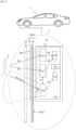
- the vehicle assembly 1 of a vehicle 2 is described with reference to figures 1 to 5 .
- the vehicle assembly 1 is otherwise called vehicle system 1.
- the vehicle 2 is a motor vehicle.
- motor vehicle is meant any type of motorized vehicle. This embodiment is taken as a non-limiting example in the remainder of the description. In the remainder of the description, the vehicle 2 is thus otherwise called motor vehicle 2.
- the vehicle assembly 1 is arranged in a lighting device or a signaling device of the motor vehicle 2, front or rear.
- the vehicle assembly 1 further comprises an exit window 12.
- the exit window 12 may or may not be part of the light module 13.
- the radar sensor 10 is described below. As illustrated in the Figure 1 , the radar sensor 10 is arranged opposite the light module 13. In a non-limiting embodiment, the radar sensor 10 is a millimeter wave radar sensor (between 24GHz and 300 GHz) or hyperfrequency (between 300MHz and 81GHz) or microwave (between 1GHz and 300GHz). In a non-limiting alternative embodiment, the radar sensor 10 operates at a radar frequency between 76GHz and 81GHz. In a non-limiting embodiment, the radar waves R1 are emitted on a frequency band between 100MHz and 5GHz. Thus, in a non-limiting example, if the sensor operates at a radar frequency of 77GHz, i.e.
- the radar sensor 10 further comprises at least one transmitter 103 configured to generate the primary radar waves R1 and at least one receiver 104 configured to process radar waves. secondary radar waves R2 received in return.
- a single electronic component can be used for both transmission and reception functions. There will thus be one or more transmitters/receivers called "transceivers" in English.
- Said transmitter 103 generates primary radar waves R1 which are subsequently emitted by the transmitting antenna 100, which when they encounter an object 3 (here a pedestrian in the non-limiting example illustrated) in the external environment of the motor vehicle 2 are reflected on said object 3.
- the radar waves thus reflected are waves transmitted in return to the radar sensor 10.
- the primary radar waves R1 and the secondary radar waves R2 are radio frequency waves.
- the radar sensor 10 comprises a plurality of transmitters 103 and a plurality of receivers 104.
- the transmitting antenna 100 is configured to transmit the primary radar waves R1 generated by the transmitter 103.
- the receiving antennas 101 are configured to receive the secondary radar waves R2 and communicate them to the receiver 104 which subsequently processes them. There is a phase shift between the secondary radar waves R2 received by the receiving antennas 101 which makes it possible to deduce therefrom the angular position of the object 3 relative to the motor vehicle 2, object 3 which is located in the external environment of the motor vehicle 2.
- the antennas 100, 101 are patch antennas or slot antennas.
- the antennas 100, 101, the transmitter 103 and the receiver 104 are arranged on a printed circuit board 105.
- the printed circuit board is a rigid printed circuit board otherwise called PCBA (“Printed Circuit Board Assembly” in English language or a flexible printed circuit board, otherwise called “Flexboard” in English language.
- the radar sensor 10 further comprises an electronic control unit 106 configured to control the transmitter 103 and the receiver 104. Since a radar sensor is known to those skilled in the art, it is not described in further detail here.
- the light module 13 is described below.
- the light module 13 is configured to perform a signaling function f1.
- said light module 13 is a daytime running light module, or a turn signal, or a reflector, or a high-mounted stop light.
- the light module 13 has an equivalent refractive index n eq at the wavelength scale ⁇ of the wavelength range ⁇ 1. It should be noted that n1 can be variable due to the optical design of the signaling function f1 (thus of the layer 15 described below, otherwise called optical layer 15) which means that the equivalent refractive index n eq is variable. This must be taken into account in the calculation of the thickness e0 described below.
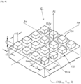
- the light module 13 comprises a sub-layer 14 and a layer 15 of patterns 150.
- the sub-layer 14 is configured to support the layer 15 of patterns 150. It is arranged directly opposite the radar sensor 10. It has a refractive index n2.
- the sub-layer 14 is formed from a plastic, glass or ceramic material. In a non-limiting example, the plastic is polycarbonate.
- the layer 15 of patterns 150 forms a sub-wavelength structured dielectric element. It has a refractive index n1 depending on the patterns 150 and their spacing, otherwise called local refractive index n1.
- the patterns 150 are defined during the optical design to perform the signaling function f1.
- the patterns 150 are used for decoupling light in a visible light guide, or are used for shaping the light beam emitted by the light module 13.
- the patterns 150 are defined so as to comply with the regulations of the light beam of the light module 13 and its visible appearance at the aesthetic level when the function f1 is switched on.
- the optical design is thus imposed without taking into account the presence or absence of the radar sensor 10, in particular so as not to create several versions of the optical layer 15.
- the dielectric element is formed from a plastic, glass or ceramic material.
- the plastic is polycarbonate. It is recalled that a dielectric material is non-conductive and therefore allows radar waves R1 to pass through, unlike a conductive material. When the radar waves R1 are emitted by the radar sensor 10, they thus first encounter the sub-layer 14, then the layer 15 of patterns 150 and finally the output glass 12.
- the layer 15 comprises the patterns 150, otherwise called structures.
- sub-wavelength it is meant that the structured dielectric material is on a smaller scale than the wavelengths ⁇ of said range ⁇ 1. The fact that the patterns 150 of the layer 15 are sub-wavelength allows the modeling of this layer 15 as a variable index layer. Otherwise, the layer 15 should be considered as a diffractive optical element.
- the layer 15 of patterns 150 is composed of unit cells 152 each comprising a pattern 150 and a portion of air surrounding said pattern 150.
- the patterns 150 are contiguous (joined) on the boundary surface between the layer 15 and the sub-layer 14. This non-limiting variant is applicable for patterns 150 in the shape of a pyramid or a portion of torus.
- A1 is the period of the network in a first direction Ax (illustrated on the Figure 4 ), and A2 is the period of the network according to a second direction Ay (illustrated on the Figure 4 ).
- Ax and Ay are arbitrary directions that are not parallel to each other.
- the second direction Ay is perpendicular to the first direction Ax.
- the unit cell 152 is a square, a hexagon, a parallelogram or any other shape that allows the boundary surface between the layer 15 and the sub-layer 14 to be periodically tiled.
- Az will be denoted a third direction perpendicular to the first direction Ax and to the second direction Ay, the whole forming a reference frame Ax, Ay, Az.
- the sub-wavelength structured dielectric element that is the layer 15 has a variable refractive index n1.
- it is a sub-wavelength structured dielectric element with a cell periodic.
- the dimensions a1, a2 of the patterns 150 change along the layer 15 varying the refractive index n1 of the layer 15, while A1 and A2 are constant.
- it is a sub-wavelength structured dielectric element with a non-periodic cell. A1 and A2 change along the layer 15 to vary the refractive index n1 of the layer 15, while the dimensions a1, a2 of the patterns 150 can remain constant.
- the layer 15 comprises variable spacings 151x, 151y between the patterns 150, namely there are different proportions of air between the patterns 150.
- A1 and A2 and also the dimensions a1, a2 of the patterns 150 can be varied to vary the refractive index of the layer 15.
- the radii of curvature are variable between the patterns 150.
- the truncation height which varies.
- sub-wavelength it is meant that the period of the grating A1, A2 is less than a quarter of one of said range ⁇ 1 of wavelengths ⁇ .
- the wavelength ⁇ considered is the smallest of the wavelengths in said range ⁇ 1.
- the period of the grating A1, A2 is less than a tenth of said wavelength ⁇ .
- this wavelength ⁇ is chosen in said range ⁇ 1 and will be that used for the formulas below.
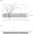
- a radar wave R1 when a radar wave R1 is emitted by the radar sensor 10, it travels to the light module 13 which comprises a thickness e0.
- the radar wave R1 arrives at the light module 13 with an angle of incidence ⁇ to which corresponds a refracted angle r.
- the radar wave R1 is reflected on the light module 13 and generates two reflected waves, one of which R11 has been reflected on the outer face of the sub-layer 14 of the light module 13 and the other inside the light module 13.
- the two reflected waves R11 and R12 are so-called first-order reflected waves which return to the radar sensor 10. These are parasitic reflections.
- the angle of incidence ⁇ is different from 0°
- the corresponding refracted angle r is also different from 0°.
- the reflected waves R11 and R12 return towards the radar sensor 10, they cause disturbances on the radar sensor 10, namely an attenuation of the signal-to-noise ratio.
- the total thickness e0 of the light module 13 will be defined so that the reflected waves R11 and R12 are in phase opposition to create destructive interference.
- the phase difference ⁇ between the two reflected waves R11 and R12 must be equal to ⁇ modulo 2 ⁇ .
- this total thickness e0 is dimensioned so that it is equal to m times said wavelength ⁇ all divided by twice an equivalent refractive index n eq of the layer 15 of patterns 150 and of the sub-layer 14 times the cosine of a refracted angle r corresponding to the angle of incidence ⁇ of the radar waves R1, with m an integer.
- the total thickness e0 can be determined so that said reflected waves R11 and R12 cancel each other out. between them.
- the wavelength ⁇ used is that which is located in the middle of the authorized ⁇ 1 range.
- An ideal total thickness e0 is defined when the angle of incidence ⁇ is equal to 0; and m is equal to 1.
- the light module 13 comprises a total thickness e0 which is between 0.8 and 1.2 times said ideal total thickness e0.
- This range of values takes into account the possible emission angles of the radar sensor 10.
- the values of the angle of incidence ⁇ are included in the possible emission angles of the radar sensor 10.
- the possible values of the angle of incidence ⁇ are defined in the technical specifications of the radar sensor 10, which means that the possible values of the angle of incidence ⁇ are in the field of vision of the radar sensor 10.
- the angle of incidence ⁇ is between 0° and +-30°. This range value of 0.8 to 1.2 makes it possible to take into account the manufacturing tolerances of the total thickness e0.
- this angle of incidence ⁇ is called the critical angle of incidence ⁇ .
- the given r corresponds to the critical angle of incidence ⁇ .
- n1 the local refractive index of the layer 15 of patterns 150
- n2 the refractive index of the sub-layer 14
- e1 equal to the height h1 of the patterns 150
- e2 the thickness of the sub-layer 14.
- n1 is a function of the position of the local zone Z1 of the patterns 150 on the layer 15 where the calculation is made.
- the equivalent refractive index n eq is a function of the position of the local zone Z1 on the layer 15.
- the calculation can be made at any location of the layer 15 of patterns 150, namely at any zone Z1.
- the local refractive index n1 is otherwise called the effective refractive index n eff and is composed of two effective refractive indices n effTE and n effTM which depend on the polarization of the incident wave, namely the primary radar wave R1, and which are expressible as a function of the local density ⁇ r , otherwise called the filling factor ⁇ r which represents the portion of material occupied by the medium with a high refractive index n1, namely here the patterns 150, as opposed to the medium with a low refractive index n0, namely here the air.
- ⁇ r represents the portion of material occupied by the medium with a high refractive index n1 over an area of a dimension of the order of one of the wavelengths ⁇ of the range ⁇ 1 of wavelengths used.
- TE which designates the polarization of the incident wave, namely here the radar wave R1 which arrives on the light module 13, perpendicular to the plane of the substrate, namely the sub-layer 14, TM the polarization parallel to the plane of the substrate, and ⁇ max the permittivity of the medium with the highest optical index, namely the patterns 150, and ⁇ min for the one with the lowest optical index, namely here air.
- the air can be replaced by a plastic material with a very low index.
- the incident wave here the radar wave R1
- the radar wave R1 illuminates the structured dielectric element, namely the layer 15, and has a wavelength ⁇ (of said range ⁇ 1) much greater than the repetition period A1, A2 of the structures 150 ( ⁇ >> ⁇ 1, and ⁇ >> ⁇ 2)
- the effective refractive index n eff2D of a 2D structure can be approximated by taking the root mean square of the effective refractive indices according to the two polarizations TM and TE in one dimension at order 0 which corresponds to the static limit.
- n eff 2 D 1 2 n effTE 2 + n effTM 2 1 2
- ⁇ r152 V 152 ⁇ 1 . ⁇ 2 . hmax
- this formula for the volume of material V 152 is valid for any unit cell 152 with a rectangular base, regardless of the shape of the pattern 150 in said unit cell 152.
- A1 and A2 can change from one unit cell 152 to another unit cell 152 as well as the maximum height hmax from one pattern 150 to another pattern 150, each unit cell 152 can have a different volume of material and consequently a different filling factor ⁇ r152 .
- ⁇ r ⁇ n ⁇ 1 n . ⁇ 2 n . hmax n . ⁇ rn ⁇ n ⁇ 1 n . ⁇ 2 n . hmax n
- the light module 13 further comprises a reflective layer 16 in the visible light range and transparent or weakly absorbing for the radar sensor 10 having a refractive index n3 for radar waves.
- the total thickness e0 of said light module 13 is equal to m times a wavelength ⁇ of said range, all divided by twice the equivalent refractive index n eq of said sub-layer 14, of said layer 15 of patterns 150 and of said reflective layer 16 times the cosine of a refracted angle r corresponding to an angle of incidence ⁇ of the radar waves R1, with m being an integer.
- the total thickness e0 of said light module 13 is equal to said wavelength ⁇ divided by twice the equivalent refractive index n eq of said sub-layer 14, of said layer 15 of patterns 150 and of said reflective layer 16 for an angle of incidence ⁇ equal to zero.
- this reflective layer 16 is thus taken into account.
- the preceding calculations must therefore also take the refractive index n3 into account.
- the reflective layer 16 covers the layer 15 of patterns 150.
- the reflective layer 16 is a layer of indium or reflective paint which covers the patterns 150.
- the radar sensor 10 comprises more than one transmitting antenna 100 and more than two receiving antennas 101.
- the light module 13 may comprise more than three layers.
- the calculation of the equivalent refractive index n eq will take into account all of the layers forming the light module 13.
- the vehicle assembly 1 further comprises an additional light module configured to perform a lighting function comprising a housing.
- the additional light module is thus a lighting light module.
- said additional light module is a front headlight, a rear light or a fog light.
Landscapes
- Engineering & Computer Science (AREA)
- Remote Sensing (AREA)
- Radar, Positioning & Navigation (AREA)
- Physics & Mathematics (AREA)
- Computer Networks & Wireless Communication (AREA)
- General Physics & Mathematics (AREA)
- Computer Security & Cryptography (AREA)
- Electromagnetism (AREA)
- Radar Systems Or Details Thereof (AREA)
- Details Of Aerials (AREA)
- Optical Radar Systems And Details Thereof (AREA)
Claims (13)
- Fahrzeuganordnung (1) für ein Fahrzeug (2), wobei die Fahrzeuganordnung (1) aufweist:- einen Radarsensor (10), der dazu ausgestaltet ist, Radarwellen (R1) über einen Bereich (Δ1) von Wellenlängen (λ) auszusenden, und- ein Leuchtmodul (13), das dazu ausgestaltet ist, eine Signalisierungsfunktion (f1) auszuführen,wobei das Leuchtmodul (13) eine Teilschicht (14) und eine Schicht (15) mit Mustern (150) aufweist, wobei die Schicht (15) mit Mustern (150) ein subwellenlängenstrukturiertes dielektrisches Element mit einer Wiederholperiode (Λ1, A2) der Muster (150) bildet, die weniger als ein Viertel der Wellenlänge (λ) des Bereichs (Δ1) beträgt, und dadurch gekennzeichnet ist, dass die Gesamtdicke (e0) des Leuchtmoduls (13) gleich dem m-Fachen einer Wellenlänge (λ) des Bereichs ist, das Ganze dividiert durch das Zweifache des äquivalenten Brechungsindex (neq) der Teilschicht (14) und der Schicht (15) mit Mustern (150) multipliziert mit dem Cosinus eines Brechungswinkels (r), der einem Einfallswinkel (θ) der Radarwellen (R1) entspricht, wobei m ganzzahlig ist.
- Fahrzeuganordnung (1) nach Anspruch 1, wobei der Radarsensor (11) ein Radarsensor mit millimetrischen Wellen oder Hyperfrequenzen oder Mikrowellen ist.
- Fahrzeuganordnung (1) nach dem vorhergehenden Anspruch, wobei die Radarwellen (R1) über ein Frequenzband zwischen 100 MHz und 5 GHz ausgesendet werden.
- Fahrzeuganordnung (1) nach einem der vorhergehenden Ansprüche, wobei die Wiederholperiode (Λ1, A2) der Muster (150) weniger als ein Zehntel der Wellenlänge (λ) der Radarwellen (R1) beträgt.
- Fahrzeuganordnung (1) nach einem der vorhergehenden Ansprüche, wobei die Muster (150) zylindrische Prismen oder rechteckig oder pyramidal oder kubisch oder Torusabschnitte sind.
- Fahrzeuganordnung (1) nach einem der vorhergehenden Ansprüche, wobei ein Muster (150) Abmessungen (a1, a2) von weniger als 0,4 mm aufweist.
- Fahrzeuganordnung (1) nach einem der vorhergehenden Ansprüche, wobei die Gesamtdicke (e0) durch die Höhe (h1) der Muster (150) und durch die Dicke (e2) der Teilschicht (14) gebildet wird.
- Fahrzeuganordnung (1) nach dem vorhergehenden Anspruch, wobei, wenn der Einfallswinkel (θ) gleich null ist, die Gesamtdicke (e0) gleich der Wellenlänge (λ) dividiert durch das Zweifache des äquivalenten Brechungsindex (neq) ist.
- Fahrzeuganordnung (1) nach einem der vorhergehenden Ansprüche, wobei die Gesamtdicke (e0) mit einem Einfallswinkel (θ) gleich arctan(d1/(2e4)) definiert ist, wobei e4 der Abstand zwischen dem Radarsensor (11) und dem Leuchtmodul (13) ist und d1 der Abstand zwischen einer Sendeantenne (100) und Empfangsantennen (101) des Radarsensors (11) ist.
- Fahrzeuganordnung (1) nach einem der vorhergehenden Ansprüche, wobei das Leuchtmodul (13) ferner eine reflektierende Schicht (16) aufweist und die Gesamtdicke (e0) des Leuchtmoduls (13) gleich dem m-Fachen einer Wellenlänge (λ) des Bereichs ist, das Ganze dividiert durch das Zweifache des äquivalenten Brechungsindex (neq) der Teilschicht (14), der Schicht (15) mit Mustern (150) und der reflektierenden Schicht (16), multipliziert mit dem Cosinus eines Brechungswinkels (r), der einem Einfallswinkel (θ) der Radarwellen (R1) entspricht, wobei m ganzzahlig ist.
- Fahrzeuganordnung (1) nach einem der vorhergehenden Ansprüche, wobei der äquivalente Brechungsindex (neq) für einen Einfallswinkel (θ) der Radarwellen (R1) gleich dem Mittelpunkt eines Sichtfelds (FOV) des Radarsensors (10) berechnet wird.
- Fahrzeuganordnung (1) nach einem der vorhergehenden Ansprüche, wobei das Leuchtmodul (13) ein Taglicht-Leuchtmodul oder eine Blinkleuchte oder ein Rückstrahler oder eine hochgesetzte Bremsleuchte ist.
- Leuchtmodul (13), das gegenüber einem Radarsensor (10) angeordnet ist, der dazu ausgestaltet ist, Radarwellen (R1) über einen Bereich (Δ1) von Wellenlängen (λ) auszusenden, wobei das Leuchtmodul (13) dazu ausgestaltet ist, eine Signalisierungsfunktion (f1) auszuführen und eine Teilschicht (14) und eine Schicht (15) mit Mustern (150) aufweist, wobei die Schicht (15) mit Mustern (150) ein subwellenlängenstrukturiertes dielektrisches Element mit einer Wiederholperiode (λ) der Muster (150) bildet, die weniger als ein Viertel der Wellenlänge (λ) des Bereichs (Δ1) beträgt, und dadurch gekennzeichnet ist, dass die Gesamtdicke (e0) des Leuchtmoduls (13) gleich dem m-Fachen der Wellenlänge (λ) ist, das Ganze dividiert durch das Zweifache des äquivalenten Brechungsindex (neq) der Teilschicht (14) und der Schicht (15) mit Mustern (150) multipliziert mit dem Cosinus eines Brechungswinkels (r), der einem Einfallswinkel (θ) der Radarwellen (R1) entspricht, wobei m ganzzahlig ist.
Applications Claiming Priority (2)
| Application Number | Priority Date | Filing Date | Title |
|---|---|---|---|
| FR2012495A FR3116908B1 (fr) | 2020-12-01 | 2020-12-01 | Ensemble de véhicule comprenant un capteur radar et un module lumineux de signalisation |
| PCT/EP2021/082051 WO2022117351A1 (fr) | 2020-12-01 | 2021-11-17 | Ensemble de véhicule comprenant un capteur radar et un module lumineux de signalisation |
Publications (2)
| Publication Number | Publication Date |
|---|---|
| EP4256376A1 EP4256376A1 (de) | 2023-10-11 |
| EP4256376B1 true EP4256376B1 (de) | 2025-04-09 |
Family
ID=74125549
Family Applications (1)
| Application Number | Title | Priority Date | Filing Date |
|---|---|---|---|
| EP21815473.0A Active EP4256376B1 (de) | 2020-12-01 | 2021-11-17 | Fahrzeuganordnung mit einem radarsensor und einem lichtemittierenden signalmodul |
Country Status (7)
| Country | Link |
|---|---|
| US (1) | US20240012137A1 (de) |
| EP (1) | EP4256376B1 (de) |
| JP (1) | JP7462117B2 (de) |
| KR (1) | KR102921670B1 (de) |
| CN (1) | CN116529625B (de) |
| FR (1) | FR3116908B1 (de) |
| WO (1) | WO2022117351A1 (de) |
Families Citing this family (5)
| Publication number | Priority date | Publication date | Assignee | Title |
|---|---|---|---|---|
| CN114174115A (zh) * | 2019-07-31 | 2022-03-11 | 法雷奥照明公司 | 汽车的照明设备 |
| EP4345491A1 (de) * | 2022-09-30 | 2024-04-03 | Aptiv Technologies Limited | Radarsensor für ein fahrzeug und verfahren zum integrieren eines radarsensors in ein fahrzeug |
| FR3148638A1 (fr) * | 2023-10-26 | 2024-11-15 | Valeo Vision | Ensemble lumineux comprenant un guide de lumière surfacique |
| WO2025219141A1 (fr) * | 2024-04-16 | 2025-10-23 | Valeo Vision | Ensemble de véhicule comprenant un capteur radar |
| EP4660661A1 (de) * | 2024-06-05 | 2025-12-10 | Aptiv Technologies AG | Kennzeichen-radarsystem |
Family Cites Families (15)
| Publication number | Priority date | Publication date | Assignee | Title |
|---|---|---|---|---|
| JP3745985B2 (ja) * | 2001-01-24 | 2006-02-15 | 古河電気工業株式会社 | 複素結合型の分布帰還型半導体レーザ素子 |
| JP2005009922A (ja) * | 2003-06-17 | 2005-01-13 | Nippon Soken Inc | 車両用物体検知装置 |
| JP2007142780A (ja) * | 2005-11-17 | 2007-06-07 | Toyoda Gosei Co Ltd | 車両用装飾部品 |
| DE102011115952A1 (de) * | 2011-10-13 | 2013-04-18 | Conti Temic Microelectronic Gmbh | Radarvorrichtung für ein Fahrzeug |
| DE102011115829A1 (de) * | 2011-10-13 | 2013-04-18 | Conti Temic Microelectronic Gmbh | Radarvorrichtung für ein Fahrzeug |
| US9925912B2 (en) * | 2015-12-07 | 2018-03-27 | GM Global Technology Operations LLC | Exterior lighting and object detection assembly |
| JP2017129419A (ja) * | 2016-01-19 | 2017-07-27 | 日本電産エレシス株式会社 | 車両 |
| EP3379286A1 (de) * | 2017-03-21 | 2018-09-26 | Volvo Car Corporation | Radaranordnung |
| US10754026B2 (en) * | 2017-06-05 | 2020-08-25 | Veoneer Us, Inc. | Surface treatment patterns to reduce radar reflection and related assemblies and methods |
| FR3077363B1 (fr) * | 2018-01-30 | 2021-08-20 | Valeo Vision | Dispositif lumineux a surface generatrice de caustique controlee formant un motif sur une surface cible |
| US11460536B2 (en) * | 2018-09-13 | 2022-10-04 | Magna Closures, Inc. | Circularly polarized automotive radar for improved signal to noise ratio |
| JP7108930B2 (ja) * | 2018-09-28 | 2022-07-29 | パナソニックIpマネジメント株式会社 | アンテナ装置、及び車載ライト装置 |
| DE102018217774A1 (de) * | 2018-10-17 | 2020-04-23 | Fraunhofer-Gesellschaft zur Förderung der angewandten Forschung e.V. | Radar- und Lichtausstrahlungsanordnung für Fahrzeuge zum Ausstrahlen von Licht und Radarstrahlung sowie Verfahren und Verwendung |
| JP2020067291A (ja) * | 2018-10-22 | 2020-04-30 | 豊田合成株式会社 | 車載センサカバー |
| JPWO2020184103A1 (de) * | 2019-03-08 | 2020-09-17 |
-
2020
- 2020-12-01 FR FR2012495A patent/FR3116908B1/fr active Active
-
2021
- 2021-11-17 EP EP21815473.0A patent/EP4256376B1/de active Active
- 2021-11-17 KR KR1020237021634A patent/KR102921670B1/ko active Active
- 2021-11-17 JP JP2023533384A patent/JP7462117B2/ja active Active
- 2021-11-17 US US18/254,909 patent/US20240012137A1/en active Pending
- 2021-11-17 WO PCT/EP2021/082051 patent/WO2022117351A1/fr not_active Ceased
- 2021-11-17 CN CN202180080453.8A patent/CN116529625B/zh active Active
Also Published As
| Publication number | Publication date |
|---|---|
| KR20230113772A (ko) | 2023-08-01 |
| KR102921670B1 (ko) | 2026-02-02 |
| WO2022117351A1 (fr) | 2022-06-09 |
| CN116529625A (zh) | 2023-08-01 |
| JP2023551887A (ja) | 2023-12-13 |
| CN116529625B (zh) | 2025-10-03 |
| FR3116908A1 (fr) | 2022-06-03 |
| FR3116908B1 (fr) | 2022-12-09 |
| EP4256376A1 (de) | 2023-10-11 |
| US20240012137A1 (en) | 2024-01-11 |
| JP7462117B2 (ja) | 2024-04-04 |
Similar Documents
| Publication | Publication Date | Title |
|---|---|---|
| EP4256376B1 (de) | Fahrzeuganordnung mit einem radarsensor und einem lichtemittierenden signalmodul | |
| FR3111197A1 (fr) | Ensemble de véhicule comprenant un capteur radar et un ensemble de couches | |
| FR2997796A1 (fr) | Dispositif en forme de diedre aplati possedant une surface equivalente radar adaptee (maximisation ou minimisation) | |
| FR2836998A1 (fr) | Controle de puissance pour des systemes radar | |
| EP4162296A1 (de) | Radar-detektionssystem für ein fahrzeug | |
| EP4082076A1 (de) | Radom für ein kraftfahrzeug, das ein dekoratives muster umfasst | |
| WO2023198458A1 (fr) | Ensemble de véhicule comprenant un capteur radar et un agencement de couches | |
| EP4363882B1 (de) | Fahrzeuganordnung mit einem radarsensor und einer gradientenindexlinse | |
| EP4256364B1 (de) | Fahrzeuganordnung mit einem radarsensor und einer ein logo bildenden schichtanordnung | |
| EP4256375B1 (de) | Fahrzeuganordnung mit einem radarsensor und einer anordnung von schichten | |
| FR3111711A1 (fr) | Ensemble de véhicule comprenant un capteur radar | |
| FR3003700A1 (fr) | Dispositif de reduction de signature radar d'antenne et systeme antennaire associe | |
| WO2013004924A1 (fr) | Dispositif pour détecter des objets tels que des mines | |
| WO2025219141A1 (fr) | Ensemble de véhicule comprenant un capteur radar | |
| FR3119896A1 (fr) | Ensemble de véhicule comprenant un capteur et un agencement de couches | |
| FR3111241A1 (fr) | Système de détection radar d’un véhicule | |
| WO2025219142A1 (fr) | Pièce pour véhicule destinée à être disposée en regard d'un cône d'émission et de réception d'un capteur de détection lidar du véhicule et comportant un système de dégivrage | |
| EP3394926A1 (de) | Antenne und antikollisionsdetektionssystem mit dieser antenne | |
| WO2024194230A1 (fr) | Système de détection de geste à sensibilité améliorée, pour un véhicule automobile |
Legal Events
| Date | Code | Title | Description |
|---|---|---|---|
| STAA | Information on the status of an ep patent application or granted ep patent |
Free format text: STATUS: UNKNOWN |
|
| STAA | Information on the status of an ep patent application or granted ep patent |
Free format text: STATUS: THE INTERNATIONAL PUBLICATION HAS BEEN MADE |
|
| PUAI | Public reference made under article 153(3) epc to a published international application that has entered the european phase |
Free format text: ORIGINAL CODE: 0009012 |
|
| STAA | Information on the status of an ep patent application or granted ep patent |
Free format text: STATUS: REQUEST FOR EXAMINATION WAS MADE |
|
| 17P | Request for examination filed |
Effective date: 20230530 |
|
| AK | Designated contracting states |
Kind code of ref document: A1 Designated state(s): AL AT BE BG CH CY CZ DE DK EE ES FI FR GB GR HR HU IE IS IT LI LT LU LV MC MK MT NL NO PL PT RO RS SE SI SK SM TR |
|
| DAV | Request for validation of the european patent (deleted) | ||
| DAX | Request for extension of the european patent (deleted) | ||
| GRAP | Despatch of communication of intention to grant a patent |
Free format text: ORIGINAL CODE: EPIDOSNIGR1 |
|
| STAA | Information on the status of an ep patent application or granted ep patent |
Free format text: STATUS: GRANT OF PATENT IS INTENDED |
|
| INTG | Intention to grant announced |
Effective date: 20241105 |
|
| GRAS | Grant fee paid |
Free format text: ORIGINAL CODE: EPIDOSNIGR3 |
|
| GRAA | (expected) grant |
Free format text: ORIGINAL CODE: 0009210 |
|
| STAA | Information on the status of an ep patent application or granted ep patent |
Free format text: STATUS: THE PATENT HAS BEEN GRANTED |
|
| AK | Designated contracting states |
Kind code of ref document: B1 Designated state(s): AL AT BE BG CH CY CZ DE DK EE ES FI FR GB GR HR HU IE IS IT LI LT LU LV MC MK MT NL NO PL PT RO RS SE SI SK SM TR |
|
| REG | Reference to a national code |
Ref country code: GB Ref legal event code: FG4D Free format text: NOT ENGLISH |
|
| REG | Reference to a national code |
Ref country code: CH Ref legal event code: EP |
|
| REG | Reference to a national code |
Ref country code: DE Ref legal event code: R096 Ref document number: 602021029009 Country of ref document: DE |
|
| REG | Reference to a national code |
Ref country code: IE Ref legal event code: FG4D Free format text: LANGUAGE OF EP DOCUMENT: FRENCH |
|
| REG | Reference to a national code |
Ref country code: NL Ref legal event code: MP Effective date: 20250409 |
|
| PG25 | Lapsed in a contracting state [announced via postgrant information from national office to epo] |
Ref country code: NL Free format text: LAPSE BECAUSE OF FAILURE TO SUBMIT A TRANSLATION OF THE DESCRIPTION OR TO PAY THE FEE WITHIN THE PRESCRIBED TIME-LIMIT Effective date: 20250409 |
|
| REG | Reference to a national code |
Ref country code: AT Ref legal event code: MK05 Ref document number: 1783993 Country of ref document: AT Kind code of ref document: T Effective date: 20250409 |
|
| PG25 | Lapsed in a contracting state [announced via postgrant information from national office to epo] |
Ref country code: FI Free format text: LAPSE BECAUSE OF FAILURE TO SUBMIT A TRANSLATION OF THE DESCRIPTION OR TO PAY THE FEE WITHIN THE PRESCRIBED TIME-LIMIT Effective date: 20250409 Ref country code: PT Free format text: LAPSE BECAUSE OF FAILURE TO SUBMIT A TRANSLATION OF THE DESCRIPTION OR TO PAY THE FEE WITHIN THE PRESCRIBED TIME-LIMIT Effective date: 20250811 Ref country code: ES Free format text: LAPSE BECAUSE OF FAILURE TO SUBMIT A TRANSLATION OF THE DESCRIPTION OR TO PAY THE FEE WITHIN THE PRESCRIBED TIME-LIMIT Effective date: 20250409 |
|
| REG | Reference to a national code |
Ref country code: LT Ref legal event code: MG9D |
|
| PG25 | Lapsed in a contracting state [announced via postgrant information from national office to epo] |
Ref country code: GR Free format text: LAPSE BECAUSE OF FAILURE TO SUBMIT A TRANSLATION OF THE DESCRIPTION OR TO PAY THE FEE WITHIN THE PRESCRIBED TIME-LIMIT Effective date: 20250710 Ref country code: NO Free format text: LAPSE BECAUSE OF FAILURE TO SUBMIT A TRANSLATION OF THE DESCRIPTION OR TO PAY THE FEE WITHIN THE PRESCRIBED TIME-LIMIT Effective date: 20250709 |
|
| PG25 | Lapsed in a contracting state [announced via postgrant information from national office to epo] |
Ref country code: PL Free format text: LAPSE BECAUSE OF FAILURE TO SUBMIT A TRANSLATION OF THE DESCRIPTION OR TO PAY THE FEE WITHIN THE PRESCRIBED TIME-LIMIT Effective date: 20250409 |
|
| PG25 | Lapsed in a contracting state [announced via postgrant information from national office to epo] |
Ref country code: BG Free format text: LAPSE BECAUSE OF FAILURE TO SUBMIT A TRANSLATION OF THE DESCRIPTION OR TO PAY THE FEE WITHIN THE PRESCRIBED TIME-LIMIT Effective date: 20250409 |
|
| PG25 | Lapsed in a contracting state [announced via postgrant information from national office to epo] |
Ref country code: HR Free format text: LAPSE BECAUSE OF FAILURE TO SUBMIT A TRANSLATION OF THE DESCRIPTION OR TO PAY THE FEE WITHIN THE PRESCRIBED TIME-LIMIT Effective date: 20250409 |
|
| PG25 | Lapsed in a contracting state [announced via postgrant information from national office to epo] |
Ref country code: AT Free format text: LAPSE BECAUSE OF FAILURE TO SUBMIT A TRANSLATION OF THE DESCRIPTION OR TO PAY THE FEE WITHIN THE PRESCRIBED TIME-LIMIT Effective date: 20250409 |
|
| PG25 | Lapsed in a contracting state [announced via postgrant information from national office to epo] |
Ref country code: RS Free format text: LAPSE BECAUSE OF FAILURE TO SUBMIT A TRANSLATION OF THE DESCRIPTION OR TO PAY THE FEE WITHIN THE PRESCRIBED TIME-LIMIT Effective date: 20250709 |
|
| PG25 | Lapsed in a contracting state [announced via postgrant information from national office to epo] |
Ref country code: IS Free format text: LAPSE BECAUSE OF FAILURE TO SUBMIT A TRANSLATION OF THE DESCRIPTION OR TO PAY THE FEE WITHIN THE PRESCRIBED TIME-LIMIT Effective date: 20250809 |
|
| PG25 | Lapsed in a contracting state [announced via postgrant information from national office to epo] |
Ref country code: LV Free format text: LAPSE BECAUSE OF FAILURE TO SUBMIT A TRANSLATION OF THE DESCRIPTION OR TO PAY THE FEE WITHIN THE PRESCRIBED TIME-LIMIT Effective date: 20250409 |
|
| PGFP | Annual fee paid to national office [announced via postgrant information from national office to epo] |
Ref country code: DE Payment date: 20251117 Year of fee payment: 5 |
|
| REG | Reference to a national code |
Ref country code: DE Ref legal event code: R097 Ref document number: 602021029009 Country of ref document: DE |
|
| PG25 | Lapsed in a contracting state [announced via postgrant information from national office to epo] |
Ref country code: SM Free format text: LAPSE BECAUSE OF FAILURE TO SUBMIT A TRANSLATION OF THE DESCRIPTION OR TO PAY THE FEE WITHIN THE PRESCRIBED TIME-LIMIT Effective date: 20250409 Ref country code: DK Free format text: LAPSE BECAUSE OF FAILURE TO SUBMIT A TRANSLATION OF THE DESCRIPTION OR TO PAY THE FEE WITHIN THE PRESCRIBED TIME-LIMIT Effective date: 20250409 |
|
| PGFP | Annual fee paid to national office [announced via postgrant information from national office to epo] |
Ref country code: FR Payment date: 20251128 Year of fee payment: 5 |
|
| PG25 | Lapsed in a contracting state [announced via postgrant information from national office to epo] |
Ref country code: CZ Free format text: LAPSE BECAUSE OF FAILURE TO SUBMIT A TRANSLATION OF THE DESCRIPTION OR TO PAY THE FEE WITHIN THE PRESCRIBED TIME-LIMIT Effective date: 20250409 |
|
| PG25 | Lapsed in a contracting state [announced via postgrant information from national office to epo] |
Ref country code: EE Free format text: LAPSE BECAUSE OF FAILURE TO SUBMIT A TRANSLATION OF THE DESCRIPTION OR TO PAY THE FEE WITHIN THE PRESCRIBED TIME-LIMIT Effective date: 20250409 |
|
| PG25 | Lapsed in a contracting state [announced via postgrant information from national office to epo] |
Ref country code: SK Free format text: LAPSE BECAUSE OF FAILURE TO SUBMIT A TRANSLATION OF THE DESCRIPTION OR TO PAY THE FEE WITHIN THE PRESCRIBED TIME-LIMIT Effective date: 20250409 |
|
| PG25 | Lapsed in a contracting state [announced via postgrant information from national office to epo] |
Ref country code: IT Free format text: LAPSE BECAUSE OF FAILURE TO SUBMIT A TRANSLATION OF THE DESCRIPTION OR TO PAY THE FEE WITHIN THE PRESCRIBED TIME-LIMIT Effective date: 20250409 |
|
| PLBE | No opposition filed within time limit |
Free format text: ORIGINAL CODE: 0009261 |
|
| STAA | Information on the status of an ep patent application or granted ep patent |
Free format text: STATUS: NO OPPOSITION FILED WITHIN TIME LIMIT |
|
| REG | Reference to a national code |
Ref country code: CH Ref legal event code: L10 Free format text: ST27 STATUS EVENT CODE: U-0-0-L10-L00 (AS PROVIDED BY THE NATIONAL OFFICE) Effective date: 20260218 |
|
| PG25 | Lapsed in a contracting state [announced via postgrant information from national office to epo] |
Ref country code: RO Free format text: LAPSE BECAUSE OF FAILURE TO SUBMIT A TRANSLATION OF THE DESCRIPTION OR TO PAY THE FEE WITHIN THE PRESCRIBED TIME-LIMIT Effective date: 20250409 |
|
| 26N | No opposition filed |
Effective date: 20260112 |