EP4256387B1 - Boîtier cms laser avec phosphore et coupleur d'entrée lumineux - Google Patents
Boîtier cms laser avec phosphore et coupleur d'entrée lumineux Download PDFInfo
- Publication number
- EP4256387B1 EP4256387B1 EP21819458.7A EP21819458A EP4256387B1 EP 4256387 B1 EP4256387 B1 EP 4256387B1 EP 21819458 A EP21819458 A EP 21819458A EP 4256387 B1 EP4256387 B1 EP 4256387B1
- Authority
- EP
- European Patent Office
- Prior art keywords
- light
- luminescent
- face
- optical element
- unit
- Prior art date
- Legal status (The legal status is an assumption and is not a legal conclusion. Google has not performed a legal analysis and makes no representation as to the accuracy of the status listed.)
- Active
Links
Images


Classifications
-
- G—PHYSICS
- G02—OPTICS
- G02B—OPTICAL ELEMENTS, SYSTEMS OR APPARATUS
- G02B19/00—Condensers, e.g. light collectors or similar non-imaging optics
- G02B19/0033—Condensers, e.g. light collectors or similar non-imaging optics characterised by the use
- G02B19/0047—Condensers, e.g. light collectors or similar non-imaging optics characterised by the use for use with a light source
- G02B19/0052—Condensers, e.g. light collectors or similar non-imaging optics characterised by the use for use with a light source the light source comprising a laser diode
-
- F—MECHANICAL ENGINEERING; LIGHTING; HEATING; WEAPONS; BLASTING
- F21—LIGHTING
- F21K—NON-ELECTRIC LIGHT SOURCES USING LUMINESCENCE; LIGHT SOURCES USING ELECTROCHEMILUMINESCENCE; LIGHT SOURCES USING CHARGES OF COMBUSTIBLE MATERIAL; LIGHT SOURCES USING SEMICONDUCTOR DEVICES AS LIGHT-GENERATING ELEMENTS; LIGHT SOURCES NOT OTHERWISE PROVIDED FOR
- F21K9/00—Light sources using semiconductor devices as light-generating elements, e.g. using light-emitting diodes [LED] or lasers
- F21K9/60—Optical arrangements integrated in the light source, e.g. for improving the colour rendering index or the light extraction
- F21K9/64—Optical arrangements integrated in the light source, e.g. for improving the colour rendering index or the light extraction using wavelength conversion means distinct or spaced from the light-generating element, e.g. a remote phosphor layer
-
- F—MECHANICAL ENGINEERING; LIGHTING; HEATING; WEAPONS; BLASTING
- F21—LIGHTING
- F21V—FUNCTIONAL FEATURES OR DETAILS OF LIGHTING DEVICES OR SYSTEMS THEREOF; STRUCTURAL COMBINATIONS OF LIGHTING DEVICES WITH OTHER ARTICLES, NOT OTHERWISE PROVIDED FOR
- F21V13/00—Producing particular characteristics or distribution of the light emitted by means of a combination of elements specified in two or more of main groups F21V1/00 - F21V11/00
- F21V13/02—Combinations of only two kinds of elements
- F21V13/08—Combinations of only two kinds of elements the elements being filters or photoluminescent elements and reflectors
-
- F—MECHANICAL ENGINEERING; LIGHTING; HEATING; WEAPONS; BLASTING
- F21—LIGHTING
- F21V—FUNCTIONAL FEATURES OR DETAILS OF LIGHTING DEVICES OR SYSTEMS THEREOF; STRUCTURAL COMBINATIONS OF LIGHTING DEVICES WITH OTHER ARTICLES, NOT OTHERWISE PROVIDED FOR
- F21V9/00—Elements for modifying spectral properties, polarisation or intensity of the light emitted, e.g. filters
- F21V9/30—Elements containing photoluminescent material distinct from or spaced from the light source
- F21V9/32—Elements containing photoluminescent material distinct from or spaced from the light source characterised by the arrangement of the photoluminescent material
-
- G—PHYSICS
- G02—OPTICS
- G02B—OPTICAL ELEMENTS, SYSTEMS OR APPARATUS
- G02B19/00—Condensers, e.g. light collectors or similar non-imaging optics
- G02B19/0004—Condensers, e.g. light collectors or similar non-imaging optics characterised by the optical means employed
- G02B19/0028—Condensers, e.g. light collectors or similar non-imaging optics characterised by the optical means employed refractive and reflective surfaces, e.g. non-imaging catadioptric systems
-
- G—PHYSICS
- G02—OPTICS
- G02B—OPTICAL ELEMENTS, SYSTEMS OR APPARATUS
- G02B19/00—Condensers, e.g. light collectors or similar non-imaging optics
- G02B19/0033—Condensers, e.g. light collectors or similar non-imaging optics characterised by the use
- G02B19/0047—Condensers, e.g. light collectors or similar non-imaging optics characterised by the use for use with a light source
- G02B19/0061—Condensers, e.g. light collectors or similar non-imaging optics characterised by the use for use with a light source the light source comprising a LED
-
- F—MECHANICAL ENGINEERING; LIGHTING; HEATING; WEAPONS; BLASTING
- F21—LIGHTING
- F21Y—INDEXING SCHEME ASSOCIATED WITH SUBCLASSES F21K, F21L, F21S and F21V, RELATING TO THE FORM OR THE KIND OF THE LIGHT SOURCES OR OF THE COLOUR OF THE LIGHT EMITTED
- F21Y2115/00—Light-generating elements of semiconductor light sources
- F21Y2115/30—Semiconductor lasers
-
- H—ELECTRICITY
- H10—SEMICONDUCTOR DEVICES; ELECTRIC SOLID-STATE DEVICES NOT OTHERWISE PROVIDED FOR
- H10H—INORGANIC LIGHT-EMITTING SEMICONDUCTOR DEVICES HAVING POTENTIAL BARRIERS
- H10H20/00—Individual inorganic light-emitting semiconductor devices having potential barriers, e.g. light-emitting diodes [LED]
- H10H20/80—Constructional details
- H10H20/85—Packages
- H10H20/851—Wavelength conversion means
- H10H20/8515—Wavelength conversion means not being in contact with the bodies
-
- H—ELECTRICITY
- H10—SEMICONDUCTOR DEVICES; ELECTRIC SOLID-STATE DEVICES NOT OTHERWISE PROVIDED FOR
- H10H—INORGANIC LIGHT-EMITTING SEMICONDUCTOR DEVICES HAVING POTENTIAL BARRIERS
- H10H20/00—Individual inorganic light-emitting semiconductor devices having potential barriers, e.g. light-emitting diodes [LED]
- H10H20/80—Constructional details
- H10H20/85—Packages
- H10H20/855—Optical field-shaping means, e.g. lenses
- H10H20/856—Reflecting means
Definitions
- the invention relates to a light generating system, an integrated light source package comprising the light generating system, and a light generating device comprising the light generating system.
- DE10201616A1 discloses a semiconductor lighting device that includes at least one semiconductor laser configured to generate a primary radiation and at least one conversion element configured to generate a longer-wave visible secondary radiation from the primary radiation, wherein the conversion element includes a semiconductor layer sequence having one or more quantum well layers, wherein the semiconductor layer sequence is homogeneously illuminated with the primary radiation.
- the growth substrate of the semiconductor layer sequence is located between the semiconductor layer sequence and the semiconductor laser, the growth substrate being oriented perpendicular to the growth direction.
- DE102008012316A1 discloses a semiconductor light source having a primary radiation source which emits electromagnetic primary radiation in a first wavelength range, and having a luminescence conversion module into which primary radiation emitted by the primary radiation source is fed.
- the luminescence conversion module contains a luminescence conversion element which absorbs primary radiation from the first wavelength range and emits electromagnetic secondary radiation in a second wavelength range.
- the luminescence conversion element is arranged on a heat sink at a distance from the primary radiation source. It has a reflector surface which reflects back into the luminescence conversion element the primary radiation which passes through the luminescence conversion element and that is not absorbed thereby and/or reflects secondary radiation in the direction of a light coupling-out surface of the luminescence conversion element.
- WO2019/008092A1 discloses a lighting device comprising a luminescent element comprising an elongated light transmissive body, the elongated light transmissive body comprising a side face, wherein the elongated light transmissive body comprises a luminescent material configured to convert at least part of a light source light selected from one or more of the UV, visible light, and IR received by the elongated light transmissive body into luminescent material radiation.
- While white LED sources can give an intensity of e.g. up to about 300 lm/mm 2 ; static phosphor converted laser white sources can give an intensity even up to about 20.000 lm/mm 2 .
- Ce doped garnets e.g. YAG, LuAG
- Ce doped garnets may be the most suitable luminescent convertors which can be used for pumping with blue laser light as the garnet matrix has a very high chemical stability.
- temperature quenching may only occur above about 200 °C.
- emission from Ce has a very fast decay time so that optical saturation can essentially be avoided. Assuming e.g. a reflective mode operation, blue laser light may be incident on a phosphor.
- the light generating system comprises a lighting unit.
- the term "lighting unit” may in embodiments also refer to a plurality of lighting units.
- the number of lighting units which may be configured to provide unit light to the luminescent element may be selected from the range of 1-64, such as 1-24, like in embodiments 2-16. However, larger numbers may also be possible, such as selected from the range of 4-50.
- the term "light source” may in principle relate to any light source known in the art. It may be a conventional (tungsten) light bulb, a low pressure mercury lamp, a high pressure mercury lamp, a fluorescent lamp, a LED (light emissive diode). In a specific embodiment, the light source comprises a solid state LED light source (such as a LED or laser diode (or “diode laser”)).
- the term "light source” may also relate to a plurality of light sources, such as 2-200 (solid state) LED light sources. Hence, the term LED may also refer to a plurality of LEDs. Further, the term “light source” may in embodiments also refer to a so-called chips-on-board (COB) light source.
- COB chips-on-board
- COB especially refers to LED chips in the form of a semiconductor chip that is neither encased nor connected but directly mounted onto a substrate, such as a PCB. Hence, a plurality of light semiconductor light source may be configured on the same substrate.
- a COB is a multi LED chip configured together as a single lighting module.
- the light source has a light escape surface.
- a light escape surface Referring to conventional light sources such as light bulbs or fluorescent lamps, it may be outer surface of the glass or quartz envelope.
- LED's it may for instance be the LED die, or when a resin is applied to the LED die, the outer surface of the resin. In principle, it may also be the terminal end of a fiber.
- escape surface especially relates to that part of the light source, where the light actually leaves or escapes from the light source.
- the light source is configured to provide a beam of light. This beam of light (thus) escapes from the light exit surface of the light source.
- the term “light source” may refer to a semiconductor light-emitting device, such as a light emitting diode (LEDs), a resonant cavity light emitting diode (RCLED), a vertical cavity laser diode (VCSELs), an edge emitting laser, etc...
- the term “light source” may also refer to an organic light-emitting diode, such as a passive-matrix (PMOLED) or an active-matrix (AMOLED).
- the light source comprises a solid-state light source (such as a LED or laser diode).
- the light source comprises a LED (light emitting diode).
- the terms “light source” or “solid state light source” may also refer to a superluminescent diode (SLED).
- the term LED may also refer to a plurality of LEDs.
- the term "light source” may in embodiments also refer to a so-called chips-on-board (COB) light source.
- COB especially refers to LED chips in the form of a semiconductor chip that is neither encased nor connected but directly mounted onto a substrate, such as a PCB. Hence, a plurality of semiconductor light sources may be configured on the same substrate.
- a COB is a multi LED chip configured together as a single lighting module.
- the term "light source” may also relate to a plurality of (essentially identical (or different)) light sources, such as 2-2000 solid state light sources.
- the light source may comprise one or more micro-optical elements (array of micro lenses) downstream of a single solid-state light source, such as a LED, or downstream of a plurality of solid-state light sources (i.e. e.g. shared by multiple LEDs).
- the light source may comprise a LED with on-chip optics.
- the light source comprises a pixelated single LEDs (with or without optics) (offering in embodiments on-chip beam steering).
- the light source may be configured to provide primary radiation, which is used as such, such as e.g. a blue light source, like a blue LED, or a green light source, such as a green LED, and a red light source, such as a red LED.
- a blue light source like a blue LED
- a green light source such as a green LED
- a red light source such as a red LED.
- Such LEDs which may not comprise a luminescent material (“phosphor”) may be indicated as direct color LEDs.
- the light source may be configured to provide primary radiation and part of the primary radiation is converted into secondary radiation. Secondary radiation may be based on conversion by a luminescent material. The secondary radiation may therefore also be indicated as luminescent material radiation.
- the luminescent material may in embodiments be comprised by the light source, such as a LED with a luminescent material layer or dome comprising luminescent material. Such LEDs may be indicated as phosphor converted LEDs or PC LEDs.
- the luminescent material may be configured at some distance ("remote") from the light source, such as a LED with a luminescent material layer not in physical contact with a die of the LED.
- the light source may be a light source that during operation emits at least light at wavelength selected from the range of 380-470 nm. However, other wavelengths may also be possible. This light may partially be used by the luminescent material.
- laser light source especially refers to a laser.
- Such laser may especially be configured to generate laser light source light having one or more wavelengths in the UV, visible, or infrared, especially having a wavelength selected from the spectral wavelength range of 200-2000 nm, such as 300-1500 nm.
- laser especially refers to a device that emits light through a process of optical amplification based on the stimulated emission of electromagnetic radiation.
- the term “laser” may refer to a solid-state laser.
- the terms “laser” or “laser light source”, or similar terms refer to a laser diode (or diode laser).
- the light source comprises a laser light source.
- the terms “laser” or “solid state laser” may refer to one or more of cerium doped lithium strontium (or calcium) aluminum fluoride (Ce:LiSAF, Ce:LiCAF), chromium doped chrysoberyl (alexandrite) laser, chromium ZnSe (Cr:ZnSe) laser, divalent samarium doped calcium fluoride (Sm:CaF 2 ) laser, Er:YAG laser, erbium doped and erbium-ytterbium codoped glass lasers, F-Center laser, holmium YAG (Ho:YAG) laser, Nd:YAG laser, NdCrYAG laser, neodymium doped yttrium calcium oxoborate Nd:YCa 4 O(BO 3 ) 3 or Nd:YCOB, neodymium doped yt
- laser or solid state laser may refer to one or more of a semiconductor laser diode, such as GaN, InGaN, AlGaInP, AlGaAs, InGaAsP, lead salt, vertical cavity surface emitting laser (VCSEL), quantum cascade laser, hybrid silicon laser, etc.
- a semiconductor laser diode such as GaN, InGaN, AlGaInP, AlGaAs, InGaAsP, lead salt, vertical cavity surface emitting laser (VCSEL), quantum cascade laser, hybrid silicon laser, etc.
- a laser may be combined with an upconverter in order to arrive at shorter (laser) wavelengths.
- an upconverter for instance, with some (trivalent) rare earth ions upconversion may be obtained or with non-linear crystals upconversion can be obtained.
- a laser can be combined with a downconverter, such as a dye laser, to arrive at longer (laser) wavelengths.
- laser light source may also refer to a plurality of (different or identical) laser light sources.
- the term “laser light source” may refer to a plurality N of (identical) laser light sources.
- N 2, or more.
- N may be at least 5, such as especially at least 8. In this way, a higher brightness may be obtained.
- laser light sources may be arranged in a laser bank (see also above).
- the laser bank may in embodiments comprise heat sinking and/or optics e.g. a lens to collimate the laser light.
- the laser light source is configured to generate laser light source light (or "laser light").
- the light source light may essentially consist of the laser light source light.
- the light source light may also comprise laser light source light of two or more (different or identical) laser light sources.
- the laser light source light of two or more (different or identical) laser light sources may be coupled into a light guide, to provide a single beam of light comprising the laser light source light of the two or more (different or identical) laser light sources.
- the light source light is thus especially collimated light source light.
- the light source light is especially (collimated) laser light source light.
- different light sources or “a plurality of different light sources”, and similar phrases, may in embodiments refer to a plurality of solid-state light sources selected from at least two different bins.
- each of the faces may be directed to a respective second reflective element including e.g. an opening for entry of the unit light.
- the accumulate areas of these openings may be essentially A4-A3.
- A4 and A3 may essentially be the same.
- the second reflective element may be a reflective coating.
- the system may be configured to provide in an operational mode white light.
- white light herein, is known to the person skilled in the art. It especially relates to light having a correlated color temperature (CCT) between about 1800 K and 20000 K, such as between 2000 and 20000 K, especially 2700-20000 K, for general lighting especially in the range of about 2700 K and 6500 K.
- the correlated color temperature (CCT) may especially be in the range of about 7000 K and 20000 K.
- the correlated color temperature (CCT) is especially within about 15 SDCM (standard deviation of color matching) from the BBL (black body locus), especially within about 10 SDCM from the BBL, even more especially within about 5 SDCM from the BBL.
- UV visible light
- visible emission light having one or more wavelengths in the range of about 380-780 nm.
- UV may especially refer to a wavelength selected from the range of 200-380 nm.
- light and radiation are herein interchangeably used, unless clear from the context that the term “light” only refers to visible light.
- the terms “light” and “radiation” may thus refer to UV radiation, visible light, and IR radiation. In specific embodiments, especially for lighting applications, the terms “light” and “radiation” refer to (at least) visible light.
- the system may further comprise a control system or may be functionally coupled to a control system.
- the control system may be configured to control the light sources and/or further light sources.
- the control system may be configured to control spectral properties of the system light, like e.g. one or more of color point and correlated color temperature.
- controlling and similar terms especially refer at least to determining the behavior or supervising the running of an element.
- controlling and similar terms may e.g. refer to imposing behavior to the element (determining the behavior or supervising the running of an element), etc., such as e.g. measuring, displaying, actuating, opening, shifting, changing temperature, etc..
- controlling and similar terms may additionally include monitoring.
- controlling and similar terms may include imposing behavior on an element and also imposing behavior on an element and monitoring the element.
- the controlling of the element can be done with a control system, which may also be indicated as "controller”.
- the control system and the element may thus at least temporarily, or permanently, functionally be coupled.
- the element may comprise the control system.
- the control system and element may not be physically coupled. Control can be done via wired and/or wireless control.
- the term "control system" may also refer to a plurality of different control systems, which especially are functionally coupled, and of which e.g. one control system may be a master control system and one or more others may be slave control systems.
- a control system may comprise or may be functionally coupled to a user interface.
- the control system may also be configured to receive and execute instructions form a remote control.
- the control system may be controlled via an App on a device, such as a portable device, like a Smartphone or iPhone, a tablet, etc..
- the device is thus not necessarily coupled to the lighting system, but may be (temporarily) functionally coupled to the lighting system.
- control system may (also) be configured to be controlled by an App on a remote device.
- the control system of the lighting system may be a slave control system or control in a slave mode.
- the lighting system may be identifiable with a code, especially a unique code for the respective lighting system.
- the control system of the lighting system may be configured to be controlled by an external control system which has access to the lighting system on the basis of knowledge (input by a user interface of with an optical sensor (e.g. QR code reader) of the (unique) code.
- the lighting system may also comprise means for communicating with other systems or devices, such as on the basis of Bluetooth, WIFI, LiFi, ZigBee, BLE or WiMAX, or another wireless technology.
- control system may control in dependence of one or more of an input signal of a user interface, a sensor signal (of a sensor), and a timer.
- timer may refer to a clock and/or a predetermined time scheme.
- the light generating system may be part of or may be applied in e.g. office lighting systems, household application systems, shop lighting systems, home lighting systems, accent lighting systems, spot lighting systems, theater lighting systems, fiber-optics application systems, projection systems, self-lit display systems, pixelated display systems, segmented display systems, warning sign systems, medical lighting application systems, indicator sign systems, decorative lighting systems, portable systems, automotive applications, (outdoor) road lighting systems, urban lighting systems, green house lighting systems, horticulture lighting, digital projection, or LCD backlighting.
- the light generating system (or luminaire) may be part of or may be applied in e.g. optical communication systems or disinfection systems.
- the invention provides an integrated light source package comprising the light generating system according to any one of the preceding claims.
- the integrated light source package may comprise a common support member configured to support the lighting unit, or at least its light source, and the optical element.
- the common support member may be configured to transport thermal energy from the light source and the luminescent element, and the optical element, to a heatsink, or the common support member may be a heatsink.
- the common support member may be a heatsink or a heat spreader.
- the system comprises an SMD package comprising the lighting unit, the luminescent element, and the optical element, and optionally also the reflective element.
- the system comprises an SMD package comprising the lighting unit, the luminescent element, the optical element, and the reflective element.
- the invention also provides a lamp or a luminaire comprising the light generating system as defined herein.
- the luminaire may further comprise a housing, optical elements, louvres, etc. etc...
- the lamp or luminaire may further comprise a housing enclosing the light generating system.
- the lamp or luminaire may comprise a light window in the housing or a housing opening, through which the system light may escape from the housing.
- the invention also provides a projection device comprising the light generating system as defined herein.
- a projection device or "projector” or “image projector” may be an optical device that projects an image (or moving images) onto a surface, such as e.g. a projection screen.
- the projection device may include one or more light generating systems such as described herein.
- the invention also provides a light generating device selected from the group of a lamp, a luminaire, a projector device, a disinfection device, and an optical wireless communication device, comprising the light generating system as defined herein.
- a lighting device or a lighting system may be configured to generate device light (or “lighting device light”) or system light (“or lighting system light”). As indicated above, the terms light and radiation may interchangeably be used.
- the lighting device may comprise a light source.
- the device light may in embodiments comprise one or more of light source light and converted light source light (such as luminescent material light).
- the lighting system may comprise a light source.
- the system light may in embodiments comprise one or more of light source light and converted light source light (such as luminescent material light).
- light and radiation are herein interchangeably used, unless clear from the context that the term “light” only refers to visible light.
- the terms “light” and “radiation” may thus refer to UV radiation, visible light, and IR radiation. In specific embodiments, especially for lighting applications, the terms “light” and “radiation” refer to visible light.
- UV radiation may in specific embodiments refer to near UV radiation (NUV). Therefore, herein also the term “(N)UV” is applied, to refer to in general UV, and in specific embodiments to NUV.
- IR radiation may in specific embodiments refer to near IR radiation (NIR). Therefore, herein also the term “(N)IR” is applied, to refer to in general IR, and in specific embodiments to NIR.
- visible light especially relates to light having a wavelength selected from the range of 380-780 nm.
- UV ultraviolet
- UV ultraviolet
- IR infrared
- IR-A near infrared
- SWIR short-wavelength infrared
- Laser diodes such as two laser diodes, may be arranged on the carrier via a holder and illuminate a phosphor tile under an angle of 60°.
- the laser diodes may be arranged in the vicinity of the phosphor such that a large part of the laser light is directed onto the phosphor.
- Such a light emitting device can be mounted on a (secondary) heat sink.
- Laser-phosphor (surface mounted device) SMD can be used in high brightness lighting applications such as adaptive front lighting systems, stage lighting, projection, medical lighting, etc. It appears desirable to improve the spectral and/or spatial light distribution of laser-phosphor SMDs.
- a laser SMD package is proposed with transmissive phosphor and using a sapphire light in-coupler for improved collection efficiency and spectral-spatial light distribution.
- the phosphor (tile) may be arranged on top of a transparent-shaped light in-coupler which may be arranged on top of a reflective heatsink.
- the angle at which the lasers are arranged and the side surfaces of the transparent-shaped light in-coupler may in embodiments be designed such that laser light is efficiently directed towards (and focused onto) the bottom surface of the phosphor tile.
- direct pumping also indirect phosphor pumping via mirrors can be used to improve focusing of the light onto the phosphor.
- the side surfaces of the transparent-shaped light in-coupler may comprise a reflector with a pinhole to further improve the efficiency.
- the bottom of the phosphor tile is pumped from multiple sides.
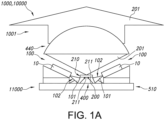
- Fig. 1a schematically depicts an embodiment of a light generating system 1000.
- the system 1000 comprises a lighting unit 100, a luminescent element 210, an optical element 400, and a reflective element 510.
- the luminescent element 210 comprises a first luminescent element face 211 and a second luminescent element face 212.
- the lighting unit 100 is especially configured to generate a beam 102 of unit light 101.
- the lighting unit 100 may comprise a light source 10 configured to generate light source light 11.
- the unit light 101 may comprise at least part of the light source light 11.
- the light source 10 may be selected from the group consisting of a laser diode and a superluminescent diode.
- FIG. 1a The embodiment schematically depicted in Fig. 1a is an embodiment of the light generating system 1000 comprising a plurality of lighting units 100 configured to irradiate different parts of the third part 423 of the external surface 410.
- Fig. 1a schematically also depicts an embodiment of an integrated light source package 10000 comprising the light generating system 1000.
- the integrated light source package 10000 may comprise a common support member 11000, configured to support directly or via intermediate elements the light source(s) 100, the optical element 400, and the luminescent element 210.
- the common support member 11000 may in embodiments essentially consist of the reflective element 510 and/or a thermally conductive element 500 (see also below).
- the reflective element 510 is configured to reflect unit light 101.
- the reflective element 510 is specular reflective.
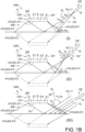
- a first embodiment I schematically depicts an embodiment wherein the lighting unit 100 provides a divergent beam 102
- embodiment II schematically depicts a focused beam 102
- embodiment III schematically depicts a (fully) collimated beam 102.
- the luminescent element 210 comprises a luminescent material 200, especially configured to convert at least part of the unit light 101 into luminescent material light 201.
- the luminescent element 210 comprises a first luminescent element face 211 and a second luminescent element face 212.
- at least part of the luminescent material 200 is configured between the first luminescent element face 211 and the second luminescent element face 212.
- the luminescent material 200 comprise a luminescent material of the type A 3 B 5 O 12 :Ce, wherein A comprises one or more of Y, La, Gd, Tb and Lu, and wherein B comprises one or more of Al, Ga, In and Sc.
- the optical element 400 comprises an external surface 410. Especially, the optical element 400 is configured between the luminescent element 210 and the reflective element 510.
- a first part 421 of the external surface 410 may be directed to the second luminescent face 212 and a second part 422 of the external surface 410 may be directed to the reflective element 510.
- a third part 423 of the externa surface 410 is configured in a light receiving relationship with the lighting unit 100. Hence, at least part of the third part may receive lighting unit light 101.
- a first area A1 of the first part 421 may be smaller than a second area A2 of the second part 422.
- the area of the first part 421 is indicated with reference A1 and the area of the second part 422 is indicated with reference A2.
- the optical element 400 is transmissive for the unit light 101.
- the optical element 400 may be selected from the group consisting of a ceramic body, a single crystal (such as alumina, like e.g. sapphire), glass, and quartz.
- the lighting unit 100 is configured such that in an operational mode the lighting unit 100 is configured to irradiate the first element face 211, especially via transmission through the optical element 400 and reflection at the reflective element 510.
- the lighting unit 100 may be configured such that in the operational mode the lighting unit 100 is configured to irradiate at least 20% of the second element face 212 via transmission through the optical element 400 and reflection at the reflective element 510.
- the lighting unit 100 may be configured such that in the operational mode the lighting unit 100 is configured to irradiate at least 20% of the second part 422 via transmission through the optical element 400, and via reflection at the reflective element 510 (downstream of the second part 422). Further, in embodiments the lighting unit 100 may be configured such that in the operational mode the lighting unit 100 is configured to irradiate at least 70% of the second element face 212.
- the optical element 400 may comprise a first face 411 comprising the first part 421, a second face 412 comprising the second part 422, and one or more third faces 413 comprising the third part 423, wherein the first face 411 and the second face 412 are configured parallel, wherein the first face 411 is in physical contact with the luminescent element 210, wherein the second face 412 is in physical contact with the reflective element 510.
- Reference 440 refers to an embodiment of (yet) a further optics, like a beam shaping element, such as a lens.
- Fig. 1a and 1b further schematically depict embodiments wherein the third angle ⁇ 3 is selected from the range of 15-75°, see especially Fig. 1b .
- the beam 102 of unit light 101 is selected from the group consisting of a divergent beam, a focused beam, and a collimated beam, see embodiments I-III, respectively.
- the lighting unit 100 may further comprise one or more second optical elements 120 configured to one or more of (i) shape the beam 102 of unit light 101, and (ii) direct the beam 102 of unit light 101.
- the one or more second optical elements 120 comprise one or more parabolic mirrors.
- Fig. 1d schematically depicts embodiments wherein the third face 413 and the first face 411 have a first mutual angle ⁇ 1,3 , and wherein the third face 413 and the second face 412 have a second mutual angle ⁇ 2,3 , wherein 100° ⁇ 1,3 ⁇ 175°, and wherein 5° ⁇ 2,3 ⁇ 80°.
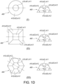
- the optical element 400 may have the shape of a frustum, with one or more edges defined by the one or more third faces 413.
- a conical frustum is schematically depicted, in embodiment II a right pyramidal frustum, and in embodiment III a hexagonal pyramidal frustum.
- Fig. 1e schematically depicts an embodiment wherein the reflective element 510 and a thermally conductive element 500 are the same element (on the left), and wherein the reflective element 510 may be a layer on the thermally conductive element 500 (on the right).
- the light generating system 1000 may comprise a thermally conductive element 500, wherein the reflective element 510 is defined by the thermally conductive element 500 or is configured as reflective layer on the thermally conductive element 500; and wherein the thermally conductive element 500 comprises a heatsink.
- Fig. 1f schematically depicts an embodiment of the light generating system 1000, comprising a second reflective element 420.
- the second reflective element 420 may be configured to reflect unit light 101 that escapes from the optical element 400 via the one or more third faces 413 back into the optical element 400.
- the third part 423 may have a third area A3.
- the one or more third faces 413 may have a fourth area A4. At least 50% of the fourth area A4 may be directed to the second reflective element 420. In embodiments, at maximum 25% of the fourth area A4 may be defined by the third area A3.
- Fig. 1g schematically depicts a cross-sectional view of a beam of light, with an optical axis O1.
- the optical axis O1 may coincide with the maximum of the spectral power distribution.
- the inner ring indicates all intensities between 100% of the spectral power (i.e. the maximum spectral power) and 1/e 2 *100% of the maximum spectral power.
- the largest outer ring may e.g. indicate all intensities between 100% of the spectral power and 10% of the maximum spectral power.
- Reference M indicates the maximum.
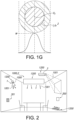
- Fig. 2 schematically depicts an embodiment of a luminaire 2 comprising the light generating system 1000 as described above.
- Reference 301 indicates a user interface which may be functionally coupled with the control system 300 comprised by or functionally coupled to the light generating system 1000.
- Fig. 2 also schematically depicts an embodiment of lamp 1 comprising the light generating system 1000.
- Reference 3 indicates a projector device or projector system, which may be used to project images, such as at a wall, which may also comprise the light generating system 1000.
- Reference 1200 refers to a lighting device, which may e.g. be selected from the group of a lamp 1, a luminaire 2, a projector device 3.
- the lighting device 1200 comprises the light generating device 1000.
- the lighting device 1200 may also comprise a disinfection device or an optical wireless communication device (comprising the light generating device 1000).
- Fig. 2 also schematically depicts an embodiment of the lighting device 1200 comprising a wall light device (such as especially wall washers).
- the lighting device 1200 may also comprise a cove lighting device (for illuminating a cove).
- the term “plurality” refers to two or more.
- the terms “substantially” or “essentially” herein, and similar terms, will be understood by the person skilled in the art.
- the terms “substantially” or “essentially” may also include embodiments with “entirely”, “completely”, “all”, etc. Hence, in embodiments the adjective substantially or essentially may also be removed.
- the term “substantially” or the term “essentially” may also relate to 90% or higher, such as 95% or higher, especially 99% or higher, even more especially 99.5% or higher, including 100%.
- the term “comprise” also includes embodiments wherein the term “comprises” means “consists of”.
- the article “a” or “an” preceding an element does not exclude the presence of a plurality of such elements.
- the invention may be implemented by means of hardware comprising several distinct elements, and by means of a suitably programmed computer.
- a device claim, or an apparatus claim, or a system claim enumerating several means, several of these means may be embodied by one and the same item of hardware.
- the mere fact that certain measures are recited in mutually different dependent claims does not indicate that a combination of these measures cannot be used to advantage.
- the invention also provides a control system that may control the device, apparatus, or system, or that may execute the herein described method or process. Yet further, the invention also provides a computer program product, when running on a computer which is functionally coupled to or comprised by the device, apparatus, or system, controls one or more controllable elements of such device, apparatus, or system.
- the invention further applies to a device, apparatus, or system comprising one or more of the characterizing features described in the description and/or shown in the attached drawings.
- the invention further pertains to a method or process comprising one or more of the characterizing features described in the description and/or shown in the attached drawings.
- the invention proposes in specific embodiments a sapphire (or other material) light in-coupler for improved collection efficiency and spectral-spatial light distribution.
- the phosphor (tile) may be arranged on top of a transparent-shaped light in-coupler which may be arranged on top of a reflective heatsink.
- the angle at which the lasers are arranged as well as the angles of the side surfaces of the transparent-shaped light in-coupler may especially be designed such that laser light is efficiently directed towards (and focused onto) the bottom surface of the phosphor tile.
- direct pumping in embodiments also indirect phosphor pumping via mirrors can be used which may improve focusing of the light onto the phosphor.
- the side surfaces of the transparent-shaped light in-coupler may in specific embodiments comprise a reflector with a pinhole to further improve the efficiency.
- the bottom of the phosphor tile may be pumped from multiple sides.
- the light generating system may comprise a lighting unit, a luminescent element, an optical element, and a reflective element.
- the light generating system may comprise a plurality of lighting units, a single luminescent element, a single optical element, and a single reflective element.
- the light generating system may comprise one or more lighting units, a single luminescent element comprising two or more luminescent materials, a single optical element, and a single reflective element.
- the light generating system may comprise (i) a plurality of arrangements, each comprising one or more lighting units, a luminescent element (comprising one or more luminescent materials), a single optical element, and (ii) one or more reflective element.
- unit light enters the optical element via the third part, propagates in the direction of the second part, may escape from the second part, and is reflected back into the optical element by the reflective element, and enters again in the optical element via the second part, and propagates to the first part, and may escape from the optical element via the first part and enter the luminescent element. There, at least part of the unit light may be converted into luminescent material light.
Landscapes
- Physics & Mathematics (AREA)
- Optics & Photonics (AREA)
- Engineering & Computer Science (AREA)
- General Physics & Mathematics (AREA)
- General Engineering & Computer Science (AREA)
- Spectroscopy & Molecular Physics (AREA)
- Microelectronics & Electronic Packaging (AREA)
- Luminescent Compositions (AREA)
- Semiconductor Lasers (AREA)
- Optical Filters (AREA)
Claims (15)
- Système générateur de lumière (1000) comprenant une unité d'éclairage (100), un élément luminescent (210), un élément optique (400) et un élément réfléchissant (510), dans lequel :- l'unité d'éclairage (100) est configurée pour générer un faisceau (102) de lumière d'unité (101) ;- l'élément luminescent (210) comprend un matériau luminescent (200) configuré pour convertir au moins une partie de la lumière d'unité (101) en lumière de matériau luminescent (201) ; dans lequel l'élément luminescent (210) comprend une première face d'élément luminescent (211) et une seconde face d'élément luminescent (212), dans lequel au moins une partie du matériau luminescent (200) est configurée entre la première face d'élément luminescent (211) et la seconde face d'élément luminescent (212) ;- l'élément optique (400) comprend une surface externe (410), dans lequel l'élément optique (400) est configuré entre l'élément luminescent (210) et l'élément réfléchissant (510), dans lequel une première partie (421) de la surface externe (410) est dirigée vers la seconde face luminescente (212), dans lequel une deuxième partie (422) de la surface externe (410) est dirigée vers l'élément réfléchissant (510), et dans lequel une troisième partie (423) de la surface externe (410) est configurée dans une relation de réception de lumière avec l'unité d'éclairage (100) ; dans lequel une première aire A1 de la première partie (421) de la surface externe (410) de l'élément optique (400) est plus petite qu'une deuxième aire A2 de la deuxième partie (422) de la surface externe (410) de l'élément optique (400), dans lequel l'élément optique (400) est transmissif pour la lumière d'unité (101) ;- l'élément réfléchissant (510) est configuré pour réfléchir la lumière d'unité (101) ; et- l'unité d'éclairage (100) est configurée de telle sorte que dans un mode fonctionnel l'unité d'éclairage (100) est configurée pour irradier la première face d'élément luminescent (211) par l'intermédiaire d'une transmission à travers l'élément optique (400) et d'une réflexion au niveau de l'élément réfléchissant (510).
- Système générateur de lumière (1000) selon la revendication 1, dans lequel l'unité d'éclairage (100) est configurée de telle sorte que dans le mode fonctionnel l'unité d'éclairage (100) est configurée pour irradier au moins 20 % de la deuxième partie (422) par l'intermédiaire d'une transmission à travers l'élément optique (400), et par l'intermédiaire d'une réflexion au niveau de l'élément réfléchissant (510) d'au moins 70 % de la seconde face d'élément (212) ; dans lequel l'élément réfléchissant (510) est un réflecteur spéculaire.
- Système générateur de lumière (1000) selon l'une quelconque des revendications précédentes, dans lequel l'élément optique (400) comprend une première face (411) comprenant la première partie (421), une deuxième face (412) comprenant la deuxième partie (422), et une ou plusieurs troisièmes faces (413) comprenant la troisième partie (423), dans lequel la première face (411) et la deuxième face (412) sont configurées parallèles, dans lequel la première face (411) est en contact physique avec l'élément luminescent (210), dans lequel la deuxième face (412) est en contact physique avec l'élément réfléchissant (510), dans lequel la troisième face (413) et la première face (411) ont un premier angle mutuel α1,3, et dans lequel la troisième face (413) et la deuxième face (412) ont un deuxième angle mutuel α2,3, dans lequel 100°≤α1,3≤175°, et dans lequel 5°≤α2,3≤80°.
- Système générateur de lumière (1000) selon l'une quelconque des revendications précédentes, dans lequel dans un premier plan (P1) perpendiculaire à la deuxième partie (422), par rapport à une première normale (N1) à la deuxième partie (422) et configurée dans le premier plan (P1), le faisceau (102) a un angle d'incidence (α1) le plus petit sur la troisième partie (423) et un angle d'incidence (α2) le plus grand sur la troisième partie (423), dans lequel la troisième partie (423) a un troisième angle (α3) avec la normale (N1), dans lequel α3>α1, et dans lequel le faisceau (102) de lumière d'unité (101) est défini par au moins 1/e2 d'un maximum d'une puissance spectrale de la lumière d'unité (101).
- Système générateur de lumière (1000) selon la revendication 4, dans lequel le troisième angle (α3) est choisi dans la plage de 15 à 75°.
- Système générateur de lumière (1000) selon l'une quelconque des revendications 4 à 5 précédentes, dans lequel le faisceau (102) de lumière d'unité (101) est choisi dans le groupe constitué par un faisceau focalisé et un faisceau collimaté.
- Système générateur de lumière (1000) selon l'une quelconque des revendications précédentes, dans lequel l'unité d'éclairage (100) comprend une source de lumière (10) configurée pour générer de la lumière de source de lumière (11), dans lequel la lumière d'unité (101) comprend au moins une partie de la lumière de source de lumière (11) ; dans lequel la source de lumière (10) est choisie dans le groupe constitué par une diode laser et une diode superluminescente.
- Système générateur de lumière (1000) selon la revendication 7, dans lequel l'unité d'éclairage (100) comprend en outre un ou plusieurs seconds éléments optiques (120) configurés pour un ou plusieurs parmi (i) mettre en forme le faisceau (102) de lumière d'unité (101), et (ii) diriger le faisceau (102) de lumière d'unité (101).
- Système générateur de lumière (1000) selon l'une quelconque des revendications précédentes, dans lequel l'élément optique (400) a la forme d'une pyramide tronquée, avec un ou plusieurs bords définis par la ou les troisièmes faces (413) telles que définies dans la revendication 3.
- Système générateur de lumière (1000) selon la revendication 9, comprenant un second élément réfléchissant (420), dans lequel le second élément réfléchissant (420) est configuré pour réfléchir de la lumière d'unité (101) qui s'échappe de l'élément optique (400) par l'intermédiaire de la ou des troisièmes faces (413) pour revenir dans l'élément optique (400), dans lequel la troisième partie (423) a une troisième aire A3, dans lequel la ou les troisièmes faces (413) ont une quatrième aire A4, dans lequel au moins 50 % de la quatrième aire A4 est dirigée vers le second élément réfléchissant (420) et dans lequel au maximum 25 % de la quatrième aire A4 est définie par la troisième aire A3.
- Système générateur de lumière (1000) selon l'une quelconque des revendications précédentes, comprenant un élément thermoconducteur (500), dans lequel l'élément réfléchissant (510) est défini par l'élément thermoconducteur (500) ou est configuré en tant que couche réfléchissante sur l'élément thermoconducteur (500) ; et dans lequel l'élément thermoconducteur (500) comprend un dissipateur de chaleur.
- Système générateur de lumière (1000) selon l'une quelconque des revendications précédentes, dans lequel l'élément optique (400) est choisi dans le groupe constitué par un corps en céramique, un cristal unique, du verre et du quartz ; et dans lequel le matériau luminescent (200) comprend un matériau luminescent du type A3B5O12:Ce. dans lequel A comprend un ou plusieurs parmi Y, La, Gd, Tb et Lu, et dans lequel B comprend un ou plusieurs parmi Al, Ga, In et Sc.
- Système générateur de lumière (1000) selon l'une quelconque des revendications précédentes, comprenant une pluralité d'unités d'éclairage (100) configurées pour irradier différentes parties de la troisième partie (423) de la surface externe (410).
- Ensemble intégré de sources de lumière (10000) comprenant le système générateur de lumière (1000) selon l'une quelconque des revendications précédentes.
- Dispositif générateur de lumière (1200) choisi dans le groupe constitué par une lampe (1), un luminaire (2), un dispositif de projecteur (3), un dispositif de désinfection et un dispositif de communication optique sans fil, comprenant le système de génération de lumière (1000) selon l'une quelconque des revendications précédentes.
Applications Claiming Priority (2)
| Application Number | Priority Date | Filing Date | Title |
|---|---|---|---|
| EP20211784 | 2020-12-04 | ||
| PCT/EP2021/083166 WO2022117455A1 (fr) | 2020-12-04 | 2021-11-26 | Boîtier smd laser avec luminophore et incoupleur de lumière |
Publications (3)
| Publication Number | Publication Date |
|---|---|
| EP4256387A1 EP4256387A1 (fr) | 2023-10-11 |
| EP4256387B1 true EP4256387B1 (fr) | 2025-05-07 |
| EP4256387C0 EP4256387C0 (fr) | 2025-05-07 |
Family
ID=73726591
Family Applications (1)
| Application Number | Title | Priority Date | Filing Date |
|---|---|---|---|
| EP21819458.7A Active EP4256387B1 (fr) | 2020-12-04 | 2021-11-26 | Boîtier cms laser avec phosphore et coupleur d'entrée lumineux |
Country Status (6)
| Country | Link |
|---|---|
| US (1) | US12332416B2 (fr) |
| EP (1) | EP4256387B1 (fr) |
| JP (1) | JP7604653B2 (fr) |
| CN (1) | CN116547472A (fr) |
| ES (1) | ES3031975T3 (fr) |
| WO (1) | WO2022117455A1 (fr) |
Families Citing this family (1)
| Publication number | Priority date | Publication date | Assignee | Title |
|---|---|---|---|---|
| CN119404047A (zh) * | 2022-06-23 | 2025-02-07 | 昕诺飞控股有限公司 | 激光源光导蜘蛛模块 |
Family Cites Families (16)
| Publication number | Priority date | Publication date | Assignee | Title |
|---|---|---|---|---|
| US7554258B2 (en) | 2002-10-22 | 2009-06-30 | Osram Opto Semiconductors Gmbh | Light source having an LED and a luminescence conversion body and method for producing the luminescence conversion body |
| DE102008012316B4 (de) * | 2007-09-28 | 2023-02-02 | OSRAM Opto Semiconductors Gesellschaft mit beschränkter Haftung | Halbleiterlichtquelle mit einer Primärstrahlungsquelle und einem Lumineszenzkonversionselement |
| US20130208478A1 (en) * | 2012-02-14 | 2013-08-15 | Xiao Pie Tao | Adaptor for converting laser devices to lighting |
| DE102012209593B4 (de) * | 2012-06-06 | 2021-08-12 | Osram Gmbh | Beleuchtungseinrichtung |
| US9140839B2 (en) * | 2013-07-15 | 2015-09-22 | Industrial Technology Research Institute | Lighting module and optical fiber lighting device using the same |
| JP6504355B2 (ja) * | 2014-06-06 | 2019-04-24 | パナソニックIpマネジメント株式会社 | ランプおよび車両用ヘッドランプ |
| WO2016037773A2 (fr) | 2014-09-11 | 2016-03-17 | Philips Lighting Holding B.V. | Module de diodes électroluminescentes à conversion de luminescence au phosphore à rendu du blanc et efficacité de conversion améliorés |
| FR3038738B1 (fr) * | 2015-07-08 | 2017-08-11 | Valeo Vision | Dispositif optique comportant au moins un convertisseur de longueur d’onde, module lumineux et dispositif d’eclairage pour vehicule automobile comportant un tel dispositif |
| US10879673B2 (en) | 2015-08-19 | 2020-12-29 | Soraa Laser Diode, Inc. | Integrated white light source using a laser diode and a phosphor in a surface mount device package |
| DE102016104616B4 (de) * | 2016-03-14 | 2021-09-23 | OSRAM Opto Semiconductors Gesellschaft mit beschränkter Haftung | Halbleiterlichtquelle |
| US10215367B2 (en) * | 2016-11-09 | 2019-02-26 | Christie Digital Systems Usa, Inc. | Apparatus for wavelength conversion |
| WO2019008092A1 (fr) | 2017-07-07 | 2019-01-10 | Philips Lighting Holding B.V. | Module concentrateur de lumière |
| JP3228571U (ja) * | 2017-09-30 | 2020-11-05 | 厦門市三安光電科技有限公司 | レーザー装置のパッケージ構造 |
| US10520165B1 (en) | 2018-07-09 | 2019-12-31 | Abl Ip Holding Llc | Laser illumination lighting device with solid medium freeform prism or waveguide |
| WO2020019085A1 (fr) | 2018-07-27 | 2020-01-30 | Optomak, Inc. | Source de lumière compacte à radiance spectrale élevée comprenant un miroir parabolique et un corps fluorescent plan-convexe |
| JP7389316B2 (ja) * | 2019-04-25 | 2023-11-30 | 日亜化学工業株式会社 | 発光装置 |
-
2021
- 2021-11-26 JP JP2023534082A patent/JP7604653B2/ja active Active
- 2021-11-26 EP EP21819458.7A patent/EP4256387B1/fr active Active
- 2021-11-26 WO PCT/EP2021/083166 patent/WO2022117455A1/fr not_active Ceased
- 2021-11-26 CN CN202180081387.6A patent/CN116547472A/zh active Pending
- 2021-11-26 ES ES21819458T patent/ES3031975T3/es active Active
- 2021-11-26 US US18/265,159 patent/US12332416B2/en active Active
Also Published As
| Publication number | Publication date |
|---|---|
| CN116547472A (zh) | 2023-08-04 |
| US20230408802A1 (en) | 2023-12-21 |
| JP2024502707A (ja) | 2024-01-23 |
| EP4256387A1 (fr) | 2023-10-11 |
| JP7604653B2 (ja) | 2024-12-23 |
| WO2022117455A1 (fr) | 2022-06-09 |
| EP4256387C0 (fr) | 2025-05-07 |
| ES3031975T3 (en) | 2025-07-14 |
| US12332416B2 (en) | 2025-06-17 |
Similar Documents
| Publication | Publication Date | Title |
|---|---|---|
| EP4018121B1 (fr) | Source de lumière à base de laser blanc de haute qualité par pompage indirecte de phosphore rouge | |
| US12104785B2 (en) | Laser-phosphor light source with improved brightness and thermal management | |
| WO2023126202A1 (fr) | Source de lumière à intensité réglable bbl à intensité élevée | |
| EP4217797B1 (fr) | Augmentation du contenu rouge dans une source de lumière à haute luminosité et à irc élevé | |
| EP4070154B1 (fr) | Combinateur de faisceau laser compact avec réflecteur à micro-prisme | |
| EP4334407B1 (fr) | Source lumineuse haute luminosité comprenant un laser bleu pompant un phosphore vert/jaune et une diode superluminescente jaune/orange pompant un phosphore rouge | |
| EP4179253B1 (fr) | Source lumineuse pixélisée à base de phosphore laser | |
| EP4256387B1 (fr) | Boîtier cms laser avec phosphore et coupleur d'entrée lumineux | |
| US20260063273A1 (en) | High-brightness laser-phosphor lighting with cct control | |
| EP4284892B1 (fr) | Phosphore laser pixélisé comprenant des carreaux de phosphore en céramique entourés de particules de phosphore dans un milieu | |
| US12366695B2 (en) | Laser-based light engine with improved thermal management using tapered fiber | |
| EP4363771B1 (fr) | Source de lumière à l'état solide intégrée et module de phosphore | |
| EP4476477B1 (fr) | Dissipateur thermique comprenant une fente à boucle fermée permettant de pomper un corps de luminophore cylindrique | |
| WO2023110396A1 (fr) | Source de lumière à haute luminosité |
Legal Events
| Date | Code | Title | Description |
|---|---|---|---|
| STAA | Information on the status of an ep patent application or granted ep patent |
Free format text: STATUS: UNKNOWN |
|
| STAA | Information on the status of an ep patent application or granted ep patent |
Free format text: STATUS: THE INTERNATIONAL PUBLICATION HAS BEEN MADE |
|
| PUAI | Public reference made under article 153(3) epc to a published international application that has entered the european phase |
Free format text: ORIGINAL CODE: 0009012 |
|
| STAA | Information on the status of an ep patent application or granted ep patent |
Free format text: STATUS: REQUEST FOR EXAMINATION WAS MADE |
|
| 17P | Request for examination filed |
Effective date: 20230704 |
|
| AK | Designated contracting states |
Kind code of ref document: A1 Designated state(s): AL AT BE BG CH CY CZ DE DK EE ES FI FR GB GR HR HU IE IS IT LI LT LU LV MC MK MT NL NO PL PT RO RS SE SI SK SM TR |
|
| DAV | Request for validation of the european patent (deleted) | ||
| DAX | Request for extension of the european patent (deleted) | ||
| REG | Reference to a national code |
Ref legal event code: R079 Free format text: PREVIOUS MAIN CLASS: G02B0019000000 Ipc: F21V0009320000 Ref country code: DE Ref legal event code: R079 Ref document number: 602021030553 Country of ref document: DE Free format text: PREVIOUS MAIN CLASS: G02B0019000000 Ipc: F21V0009320000 |
|
| GRAP | Despatch of communication of intention to grant a patent |
Free format text: ORIGINAL CODE: EPIDOSNIGR1 |
|
| STAA | Information on the status of an ep patent application or granted ep patent |
Free format text: STATUS: GRANT OF PATENT IS INTENDED |
|
| RIC1 | Information provided on ipc code assigned before grant |
Ipc: H01L 33/60 20100101ALI20241120BHEP Ipc: H01L 33/50 20100101ALI20241120BHEP Ipc: F21K 9/64 20160101ALI20241120BHEP Ipc: G02B 19/00 20060101ALI20241120BHEP Ipc: F21Y 115/30 20160101ALI20241120BHEP Ipc: F21V 13/08 20060101ALI20241120BHEP Ipc: F21V 9/32 20180101AFI20241120BHEP |
|
| INTG | Intention to grant announced |
Effective date: 20241203 |
|
| GRAS | Grant fee paid |
Free format text: ORIGINAL CODE: EPIDOSNIGR3 |
|
| GRAA | (expected) grant |
Free format text: ORIGINAL CODE: 0009210 |
|
| STAA | Information on the status of an ep patent application or granted ep patent |
Free format text: STATUS: THE PATENT HAS BEEN GRANTED |
|
| AK | Designated contracting states |
Kind code of ref document: B1 Designated state(s): AL AT BE BG CH CY CZ DE DK EE ES FI FR GB GR HR HU IE IS IT LI LT LU LV MC MK MT NL NO PL PT RO RS SE SI SK SM TR |
|
| REG | Reference to a national code |
Ref country code: GB Ref legal event code: FG4D |
|
| REG | Reference to a national code |
Ref country code: CH Ref legal event code: EP |
|
| REG | Reference to a national code |
Ref country code: DE Ref legal event code: R096 Ref document number: 602021030553 Country of ref document: DE |
|
| REG | Reference to a national code |
Ref country code: IE Ref legal event code: FG4D |
|
| U01 | Request for unitary effect filed |
Effective date: 20250526 |
|
| U07 | Unitary effect registered |
Designated state(s): AT BE BG DE DK EE FI FR IT LT LU LV MT NL PT RO SE SI Effective date: 20250603 |
|
| REG | Reference to a national code |
Ref country code: ES Ref legal event code: FG2A Ref document number: 3031975 Country of ref document: ES Kind code of ref document: T3 Effective date: 20250714 |
|
| PG25 | Lapsed in a contracting state [announced via postgrant information from national office to epo] |
Ref country code: NO Free format text: LAPSE BECAUSE OF FAILURE TO SUBMIT A TRANSLATION OF THE DESCRIPTION OR TO PAY THE FEE WITHIN THE PRESCRIBED TIME-LIMIT Effective date: 20250807 Ref country code: GR Free format text: LAPSE BECAUSE OF FAILURE TO SUBMIT A TRANSLATION OF THE DESCRIPTION OR TO PAY THE FEE WITHIN THE PRESCRIBED TIME-LIMIT Effective date: 20250808 |
|
| PG25 | Lapsed in a contracting state [announced via postgrant information from national office to epo] |
Ref country code: PL Free format text: LAPSE BECAUSE OF FAILURE TO SUBMIT A TRANSLATION OF THE DESCRIPTION OR TO PAY THE FEE WITHIN THE PRESCRIBED TIME-LIMIT Effective date: 20250507 |
|
| PG25 | Lapsed in a contracting state [announced via postgrant information from national office to epo] |
Ref country code: HR Free format text: LAPSE BECAUSE OF FAILURE TO SUBMIT A TRANSLATION OF THE DESCRIPTION OR TO PAY THE FEE WITHIN THE PRESCRIBED TIME-LIMIT Effective date: 20250507 |
|
| PG25 | Lapsed in a contracting state [announced via postgrant information from national office to epo] |
Ref country code: RS Free format text: LAPSE BECAUSE OF FAILURE TO SUBMIT A TRANSLATION OF THE DESCRIPTION OR TO PAY THE FEE WITHIN THE PRESCRIBED TIME-LIMIT Effective date: 20250807 |
|
| PG25 | Lapsed in a contracting state [announced via postgrant information from national office to epo] |
Ref country code: IS Free format text: LAPSE BECAUSE OF FAILURE TO SUBMIT A TRANSLATION OF THE DESCRIPTION OR TO PAY THE FEE WITHIN THE PRESCRIBED TIME-LIMIT Effective date: 20250907 |
|
| U20 | Renewal fee for the european patent with unitary effect paid |
Year of fee payment: 5 Effective date: 20251126 |
|
| PGFP | Annual fee paid to national office [announced via postgrant information from national office to epo] |
Ref country code: GB Payment date: 20251125 Year of fee payment: 5 |
|
| PG25 | Lapsed in a contracting state [announced via postgrant information from national office to epo] |
Ref country code: SM Free format text: LAPSE BECAUSE OF FAILURE TO SUBMIT A TRANSLATION OF THE DESCRIPTION OR TO PAY THE FEE WITHIN THE PRESCRIBED TIME-LIMIT Effective date: 20250507 |
|
| PG25 | Lapsed in a contracting state [announced via postgrant information from national office to epo] |
Ref country code: CZ Free format text: LAPSE BECAUSE OF FAILURE TO SUBMIT A TRANSLATION OF THE DESCRIPTION OR TO PAY THE FEE WITHIN THE PRESCRIBED TIME-LIMIT Effective date: 20250507 |
|
| PG25 | Lapsed in a contracting state [announced via postgrant information from national office to epo] |
Ref country code: SK Free format text: LAPSE BECAUSE OF FAILURE TO SUBMIT A TRANSLATION OF THE DESCRIPTION OR TO PAY THE FEE WITHIN THE PRESCRIBED TIME-LIMIT Effective date: 20250507 |
|
| PGFP | Annual fee paid to national office [announced via postgrant information from national office to epo] |
Ref country code: ES Payment date: 20251209 Year of fee payment: 5 |
|
| PLBE | No opposition filed within time limit |
Free format text: ORIGINAL CODE: 0009261 |
|
| STAA | Information on the status of an ep patent application or granted ep patent |
Free format text: STATUS: NO OPPOSITION FILED WITHIN TIME LIMIT |
|
| REG | Reference to a national code |
Ref country code: CH Ref legal event code: L10 Free format text: ST27 STATUS EVENT CODE: U-0-0-L10-L00 (AS PROVIDED BY THE NATIONAL OFFICE) Effective date: 20260318 |
|
| 26N | No opposition filed |
Effective date: 20260210 |