EP4256755B1 - Commutateur de champ apl avec attribution de puissance dynamique - Google Patents
Commutateur de champ apl avec attribution de puissance dynamique Download PDFInfo
- Publication number
- EP4256755B1 EP4256755B1 EP22710810.7A EP22710810A EP4256755B1 EP 4256755 B1 EP4256755 B1 EP 4256755B1 EP 22710810 A EP22710810 A EP 22710810A EP 4256755 B1 EP4256755 B1 EP 4256755B1
- Authority
- EP
- European Patent Office
- Prior art keywords
- power
- apl
- field switch
- port
- controller
- Prior art date
- Legal status (The legal status is an assumption and is not a legal conclusion. Google has not performed a legal analysis and makes no representation as to the accuracy of the status listed.)
- Active
Links
Images


Classifications
-
- H—ELECTRICITY
- H04—ELECTRIC COMMUNICATION TECHNIQUE
- H04L—TRANSMISSION OF DIGITAL INFORMATION, e.g. TELEGRAPHIC COMMUNICATION
- H04L12/00—Data switching networks
- H04L12/02—Details
- H04L12/10—Current supply arrangements
Definitions
- the disclosure relates generally to APL field switches for use in process control networks.
- Ethernet Advanced Physical Layer (APL) specification is based on an industry standard (IEEE 802.3cg) for the physical layer for an Ethernet based, two-wire process control network.
- IEEE 802.3cg industry standard for the physical layer for an Ethernet based, two-wire process control network.
- An Ethernet-APL network enables data rates of up to 10 Megabits per second (Mbps) full duplex.
- the Ethernet-APL network supports data transmission distances of up to 1,000 meters, power transmission over the same two wires that transmit data, multidrop, intrinsic safety, Ethernet connections to field devices, and other process control needs.
- Ethernet networking can be found in a number of books, including, for example, Sterling & Wissler, The Industrial Ethernet Networking Guide, 2003 (ISBN 0-7668-4210-X), published by Delmar Learning .
- Power and Ethernet data can be transmitted over the same twisted pair of wires because the power domain and the data domain reside in different frequency domains. Being in different frequency domains enables power and data to be carried simultaneously on the same twisted wire pair and yet be separated into individual DC power and AC data components when necessary.
- An Ethernet-APL network utilizes a trunk and spur topology.
- the APL two-wire trunk can transmit high power for long runs of up to 1,000 meters.
- APL two-wire spurs carry lower power for shorter runs from the trunk to field devices, up to 200 meters.
- APL field switches connect the APL trunk to APL spurs extending from the field switch.
- the field switch includes a number of ports for connecting the spurs to the field switch.
- Each port forms part of a respective channel that includes a power/data line connected to the port that transmits power received into the APL field switch to the port and transmits Ethernet data between the port and the APL trunk.
- Each power/data line includes a power line segment that transmits power only and a data line segment that transmits data only.
- An Ethernet switch in the data line segment receives and transmits Ethernet data through the data line segment. Power and data is transmitted through the two-wire spur connecting the port and a field device.
- the APL field switch receives power for distribution to the field switch ports through the network trunk itself or from an external auxiliary DC power source.
- An auxiliary DC power source typically delivers more power than what is available through the network trunk.
- the total power available to the APL field switch available to ports depends on the power source - the trunk or auxiliary DC source. The maximum power sent through the ports cannot exceed the power received into the APL field switch.
- APL field switches may also "cascade", that is, an upstream APL field switch may provide power to a downstream APL field switch.
- the total power supplied to the upstream APL field switch must be sufficient to power the field devices attached to the upstream APL field switch and to power the field devices attached to the downstream APL field switch (and any further downstream APL field switches).
- the APL standard defines multiple Power Classes that can be applied to each port of the APL field switch.
- a Power Class defines the maximum power available at a port that can be transmitted through a spur connected to the port.
- the APL standard defines four Power Classes, each Power Class associated with a different maximum power output: Power Class A, Power Class B, Power Class C, and Power Class D.
- Each Power Class is associated with a power profile having predefined voltage and power parameters that define the maximum power output of the port. Some Power Classes allow more power output than other Power Classes.
- Each field device attached to a port through a spur has its own independent power requirement that may differ among the attached field devices.
- a field device must be attached to a port associated with a Power Class sufficient to power the field device.
- an APL field switch is manufactured having a set number of ports (for example, 8, 12, 16, or 24 ports).
- the APL field switch must limit the number and types of Power Classes associated with the set number of ports to comply with maximum power requirements.
- a manufacturer may provide multiple models of a 24-port APL field switch, each model with ports having a different combination of associated Power Classes.
- APL field switch models for each set number of ports can be overwhelming, requiring the manufacturer to comprise and offer just a subset of the different possible combinations. Customers will also have to make compromises in their field switch selections. Additionally, customers may have to accept the manufacturer's choice of location of the ports of each Power Class (left side, right side, etc.)
- An APL field switch customer may have use cases with varying numbers of field devices attached to the field switch, and different required Power Classes to deliver adequate power to the different field devices attached to the ports.
- the APL field switch provides a default Power Class allocation to each port.
- the default Power Class allocation may depend on the power source connected to the APL Field Switch. The total allocated power cannot exceed the total power available to the ports.
- the current-limiting power protection module 56 sets the Power Class of the channel by setting the maximum current flow through the channel power line 47.
- the APL specification defines a number of Power Classes (the current APL specification definitions of the Power Classes may be subject to change, but each Power Class will be associated with a respective maximum power).
- a Power Class applicable to an APL field switch channel defines the maximum amount of power in watts at a maximum voltage that can be provided by a channel to the port 50.
- Power Classes A, B, and C are intended for intrinsically safe-rated channels for areas with explosive atmospheres but can also be used with ports not intended for intrinsically-safe use.
- the current-limiting power protection module 56 includes a selectively adjustable current-limiting device 58 represented as a variable resistor in Figure 3 . Possible embodiments of the user-adjustable current-limiting device are described later below.
- the user can selectively set the maximum current flow (amperage) that will activate the current-limiting device to prevent the current flow from exceeding the set maximum current flow that can be transmitted through the port 50.
- User selection of the Power Class of a channel 48 by way of setting the maximum current setting of the current-limiting device is discussed in greater detail below.
- the power flows from the current-limiting power protection module 56 to a voltage power protection module 60.
- the power protection module 60 prevents an overvoltage or surge condition and can be realized as a crowbar circuit represented by the impedance 62.
- a crowbar circuit operates by putting a short circuit or low resistance path across the voltage output.
- a crowbar circuit may be implemented using, for example, a thyristor, TRIAC, trisil, or thyratron as the shorting device.
- the power management module may in possible embodiments be realized as a system on a chip (SoC) that may include the microcontroller along with other peripherals, including a graphics processing unit (GPU), a Wi-Fi module, one or more coprocessors, and the like.
- SoC system on a chip
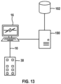
- FIG 13 illustrates use of the power protection module 64 forming part of a networked distributed computing system.
- the computing system includes a server 100 networked with the engineering workstation 16.
- the server 100 also has access to a database 102 local with the server.
- the database could be located in the back end or also be hosted in the Cloud or on another server remote from the server 100.
- the application GUI 72 is displayed on the engineering workstation 16.
- the engineering workstation 16 queries the APL field switch 30 through the process control network 10 and receives data representing the current state of the APL field switch and field switch channels. User interactions with the GUI 72 are transferred between the workstation 16 and the server 100.
- the server 100 determines whether a proposed change in Power Class of a channel is possible.
- the server 100 can store the data associated with the APL field switch and a history of changes in APL field switch state in the database 102.
- the server 100 can query the database 102 for the data needed for initially displaying the GUI 72 instead of having the APL field switch queried for that data.
Landscapes
- Engineering & Computer Science (AREA)
- Computer Networks & Wireless Communication (AREA)
- Signal Processing (AREA)
- Small-Scale Networks (AREA)
- Direct Current Feeding And Distribution (AREA)
- Power Sources (AREA)
Claims (18)
- Commutateur de champ APL (30, 32) pour un réseau de commande industriel (10) qui permet une affectation de puissance dynamique sélectionnable par l'utilisateur à un dispositif de champ connecté (26, 36, 40), le commutateur de champ APL (30, 32) comprenant :des bornes de puissance (35, 37) et des bornes de données (39) qui sont chacune configurées pour recevoir de la puissance dans le commutateur de champ APL (30, 32), les bornes de données (39) étant en outre configurées pour transmettre des données vers et hors du commutateur de champ APL (30, 32) ;une pluralité de canaux (48), chaque canal (48) comprenant un port (50) et une ligne de puissance/de données de canal (43, 47) connectant le port (50) aux bornes de puissance (35, 37) et aux bornes de données (39) ;chaque port (50) de la pluralité de canaux (48) étant configuré pour être connecté à une dérivation APL à deux fils pour connecter le port (50) à un dispositif de champ APL (26, 36, 40) à travers la dérivation APL, le port (50) étant associé à une classe de puissance par défaut d'une pluralité de classes de puissance ;la ligne de puissance/de données de canal (43, 47) de chaque canal (48) étant configurée pour transmettre de la puissance des bornes de puissance (35, 37) au port de canal (50) et pour transmettre des données entre le port de canal (50) et les bornes de données (39), la ligne de puissance/de données de canal (43, 47) comprenant un segment de ligne de puissance (49) connecté au port de canal (50) et configuré pour transmettre de la puissance électrique reçue des bornes de puissance (35, 37) au port de canal (50) ;un dispositif de limitation de puissance ajustable étant disposé dans le segment de ligne de puissance (49), le dispositif de limitation de puissance étant apte à être mis sélectivement en fonctionnement dans une pluralité d'états de fonctionnement respectifs, dans lequel, lorsque le dispositif de limitation de puissance est dans l'un des états de fonctionnement de la pluralité d'états de fonctionnement, une transmission maximale respective de puissance électrique à travers le dispositif de limitation de puissance active le dispositif de limitation de puissance et ainsi limite, réduit, ou arrête la transmission de puissance électrique à travers le segment de ligne de puissance (49), chaque état de fonctionnement étant associé à une classe de puissance différente ; etun dispositif de commande (64) étant connecté au dispositif de limitation de puissance de chaque canal (48) de la pluralité de canaux (48), le dispositif de commande (64) comprenant un programme logiciel informatique (70) incorporé dans un support exécutable non transitoire lisible par ordinateur (68) pour faire fonctionner le dispositif de commande (64), le dispositif de commande (64) étant configuré pour recevoir une entrée utilisateur demandant au dispositif de commande (64) de définir une classe de puissance d'un port (50) sélectionné de la pluralité de canaux (48) à une classe de puissance souhaitée et, en réponse à l'entrée utilisateur, émettre un signal de commande par le biais de la connexion au dispositif limiteur de puissance connecté au port (50) sélectionné qui définit l'état de fonctionnement du dispositif limiteur de puissance à l'état de fonctionnement associé à la classe de puissance souhaitée,dans lequel l'utilisateur peut modifier sélectivement la classe de puissance de chaque port (50) pour répondre aux besoins du réseau de commande industriel (10).
- Commutateur de champ APL (30, 32) selon la revendication 1, dans lequel le commutateur de champ APL (30, 32) est apte à mettre à disposition une puissance maximale totale aux ports (50) du dispositif de champ (26, 36, 40), et le dispositif de commande (64) est configuré pour ne pas modifier la classe de puissance du port (50) sélectionné en réponse à l'entrée utilisateur si la modification de la classe de puissance pouvait amener la puissance maximale transmissible aux ports (50) à dépasser la puissance maximale totale disponible du commutateur de champ APL (30, 32).
- Commutateur de champ APL (30, 32) selon la revendication 1, dans lequel l'entrée utilisateur est transmise à partir d'une interface utilisateur mise en œuvre par ordinateur qui est accessible de l'extérieur du commutateur de champ APL (30, 32).
- Commutateur de champ APL (30, 32) selon la revendication 3, dans lequel l'interface utilisateur est une interface utilisateur graphique (72) qui répertorie chaque port (50) de la pluralité de canaux (48) et la classe de puissance actuelle de chaque port (50) de la pluralité de canaux (48), et permet à l'utilisateur de définir la classe de puissance souhaitée d'un port (50) sélectionné de la pluralité de canaux (48) pour générer l'entrée utilisateur pour le dispositif de commande (64).
- Commutateur de champ APL (30, 32) selon la revendication 4, dans lequel l'interface utilisateur graphique (72) est générée par le logiciel de dispositif de commande (70) ; ou dans lequel l'interface utilisateur graphique (72) est générée par un logiciel stocké sur un support exécutable non transitoire lisible par ordinateur (68) distinct du logiciel de dispositif de commande (70).
- Commutateur de champ APL (30, 32) selon la revendication 3, dans lequel l'interface utilisateur peut être connectée de manière opérationnelle à une base de données (102) ;
l'interface utilisateur est configurée pour stocker et récupérer, dans et depuis la base de données (102), des données nécessaires à l'interface utilisateur pour permettre à un utilisateur d'affecter sélectivement des classes de puissance parmi les ports (50) de la pluralité de canaux (48). - Commutateur de champ APL (30, 32) selon la revendication 6, dans lequel la base de données (102) est stockée sur un serveur (100) distant du commutateur de champ APL (30, 32).
- Commutateur de champ APL (30, 32) selon la revendication 3, dans lequel le dispositif de commande (64) est configuré pour recevoir une entrée utilisateur demandant au dispositif de commande (64) de définir la classe de puissance de chaque port (50) de la pluralité de canaux (48) à la classe de puissance par défaut du port (50) et, en réponse à l'entrée utilisateur, émettre des signaux de commande aux dispositifs de limitation de puissance connectés aux ports (50) qui définissent l'état de fonctionnement de chaque dispositif de limitation de puissance à l'état de fonctionnement associé à la classe de puissance par défaut du port (50) raccordé au dispositif de limitation de puissance.
- Commutateur de champ APL (30, 32) selon la revendication 8, dans lequel l'interface utilisateur peut être connectée de manière opérationnelle à une base de données (102) ;
l'interface utilisateur (102) est configurée pour stocker et récupérer, dans et depuis la base de données (102), des données nécessaires à l'interface utilisateur pour permettre à un utilisateur de demander au dispositif de commande (64) de définir chaque port (50) de la pluralité de canaux (48) à la classe de puissance par défaut du port (50). - Commutateur de champ APL (30, 32) selon la revendication 8, dans lequel le commutateur de champ APL (30, 32) comprend un premier ensemble par défaut d'affectations de classe de puissance de port lorsque le commutateur de champ APL (30, 32) est alimenté par les bornes de données (39) et un second ensemble par défaut d'affectations de classe de puissance de port différent du premier ensemble lorsque le commutateur de champ APL (30, 32) est alimenté par les bornes de puissance (35, 37) ; et
le dispositif de commande (64) est configuré pour définir les classes de puissance des ports (50) de la pluralité de canaux (48) en fonction du premier ensemble par défaut de classes de puissance de port si le commutateur de champ APL (30, 32) est alimenté par les bornes de données (39) et pour définir les classes de puissance des ports (50) de la pluralité de canaux (48) en fonction du second ensemble par défaut de classes de puissance de port si le commutateur de champ APL (30, 32) est alimenté par les bornes de puissance (35, 37) lorsque le dispositif de commande (64) reçoit l'entrée utilisateur demandant au dispositif de commande (64) de définir la classe de puissance de chaque port (50) à la classe de puissance par défaut du port (50). - Commutateur de champ APL (30, 32) selon la revendication 3, dans lequel l'interface utilisateur est configurée pour afficher, à un utilisateur, des données représentant les classes de puissance actuelles attribuées aux ports (50) du commutateur de champ APL (30, 32) et est en outre configurée pour interroger le commutateur de champ APL (30, 32) pour les données affichées à l'utilisateur.
- Commutateur de champ APL (30, 32) selon la revendication 1, dans lequel le commutateur de champ APL (30, 32) est apte à transmettre en cascade une puissance électrique à un autre commutateur de champ APL (30, 32) et le dispositif de commande (64) est configuré pour recevoir une entrée utilisateur sélectivement permettant au commutateur de champ APL (30, 32) de transmettre en cascade une puissance ou ne permettant pas au commutateur de champ APL (30, 32) de transmettre en cascade une puissance.
- Commutateur de champ APL (30, 32) selon la revendication 1, dans lequel chaque dispositif de limitation de puissance de la pluralité de canaux (48) est un dispositif de limitation de courant (58).
- Commutateur de champ APL (30, 32) selon la revendication 1, dans lequel au moins un dispositif de limitation de courant (58) de la pluralité de canaux (48) comprend l'un des éléments suivants (a), (b), (c) et (d) :(a) un fusible électronique (74) ;(b) une pluralité de fusibles PTC (69) agencés en parallèle, chaque fusible PTC (69) étant en série avec un relais (71) connecté à et commandé par le dispositif de commande (64) ;(c) un circuit de limitation de courant constant ; et(d) un circuit de limitation de courant de repli.
- Commutateur de champ APL (30, 32) selon la revendication 14, dans lequel l'au moins un dispositif de limitation de courant (58) comprend le fusible électronique (74), le fusible électronique (74) étant connecté à une résistance à résistance variable présentant une résistance pouvant être sélectionnée parmi une pluralité de résistances ;le fusible électronique (74) est configuré de sorte que la résistance de la résistance définisse le flux de courant maximal à travers le fusible électronique qui activera le fusible électronique ; etle dispositif de commande (64) est configuré pour transmettre un signal de commande à l'au moins un dispositif de limitation de courant (58) qui définit la résistance de la résistance.
- Commutateur de champ APL (30, 32) selon la revendication 15, dans lequel la résistance variable est un potentiomètre numérique (76) ; ou dans lequel la résistance variable est un potentiomètre numérique de type échelle (76) ou un potentiomètre numérique de type relais (77).
- Commutateur de champ APL (30, 32) selon la revendication 1, dans lequel le dispositif de commande (64) est configuré pour définir la classe de puissance de chaque port (50) de la pluralité de canaux (48) à une classe de puissance par défaut respective en l'absence d'un utilisateur définissant la classe de puissance du port (50).
- Commutateur de champ APL (30, 32) selon la revendication 1, dans lequel le dispositif de commande (64) est configuré pour recevoir le signal d'entrée par le biais d'au moins l'une parmi (a) et (b) :(a) une connexion filaire ou sans fil qui est indépendante des bornes de données (39), et(b) une connexion qui transmet le signal d'entrée à travers les bornes de données (39) du commutateur de champ APL (30, 32).
Applications Claiming Priority (2)
| Application Number | Priority Date | Filing Date | Title |
|---|---|---|---|
| US202163152432P | 2021-02-23 | 2021-02-23 | |
| PCT/US2022/017477 WO2022182727A1 (fr) | 2021-02-23 | 2022-02-23 | Commutateur de champ apl avec attribution de puissance dynamique |
Publications (2)
| Publication Number | Publication Date |
|---|---|
| EP4256755A1 EP4256755A1 (fr) | 2023-10-11 |
| EP4256755B1 true EP4256755B1 (fr) | 2025-07-02 |
Family
ID=80781054
Family Applications (1)
| Application Number | Title | Priority Date | Filing Date |
|---|---|---|---|
| EP22710810.7A Active EP4256755B1 (fr) | 2021-02-23 | 2022-02-23 | Commutateur de champ apl avec attribution de puissance dynamique |
Country Status (5)
| Country | Link |
|---|---|
| US (1) | US12476834B2 (fr) |
| EP (1) | EP4256755B1 (fr) |
| JP (1) | JP7670838B2 (fr) |
| CN (1) | CN116941223A (fr) |
| WO (1) | WO2022182727A1 (fr) |
Families Citing this family (13)
| Publication number | Priority date | Publication date | Assignee | Title |
|---|---|---|---|---|
| EP4256755B1 (fr) * | 2021-02-23 | 2025-07-02 | Phoenix Contact Development and Manufacturing, Inc. | Commutateur de champ apl avec attribution de puissance dynamique |
| EP4568210A3 (fr) * | 2021-02-23 | 2025-07-23 | Phoenix Contact Development and Manufacturing, Inc. | Commutateur de champ apl a detection automatique de protocole |
| LU500592B1 (de) * | 2021-08-30 | 2023-02-28 | Phoenix Contact Gmbh & Co | Netzwerk-Kopplungseinrichtung für ein Netzwerk und Netzwerk mit einer Netzwerk- Kopplungseinrichtung |
| US20240118798A1 (en) * | 2022-10-10 | 2024-04-11 | Schneider Electric Systems Usa, Inc. | Configuration sourced direct from ethernet advanced physical layer field device |
| US20240118681A1 (en) * | 2022-10-10 | 2024-04-11 | Schneider Electric Systems Usa, Inc. | Systems and methods for implementing machine learning in a local apl edge device with power constraints |
| US12592559B2 (en) | 2022-12-19 | 2026-03-31 | Rosemount Inc. | Field device current limiting |
| US12218775B2 (en) | 2022-12-19 | 2025-02-04 | Rosemount Inc. | Advanced physical layer (APL) adapter for legacy field devices |
| US12316469B2 (en) * | 2023-02-07 | 2025-05-27 | Fisher-Rosemount Systems Inc. | Secondary control for de-energizing safety field devices with digital protocols |
| US20240264585A1 (en) * | 2023-02-07 | 2024-08-08 | Fisher-Rosemount Systems Inc. | High Availability Networking Device |
| CN116661360A (zh) * | 2023-06-30 | 2023-08-29 | 浙江中控技术股份有限公司 | 基于apl的万能信号边缘采集系统、方法及设备 |
| CN121548973A (zh) * | 2023-07-06 | 2026-02-17 | 倍加福欧洲股份有限公司 | 一种输入/输出交换设备 |
| US20250247261A1 (en) * | 2024-01-31 | 2025-07-31 | Analog Devices, Inc. | Physical-layer signaling techniques for maintaining dc line balance |
| US12493315B2 (en) | 2024-04-30 | 2025-12-09 | Rosemount Inc. | Ethernet-APL field device having reduced energy consumption |
Family Cites Families (89)
| Publication number | Priority date | Publication date | Assignee | Title |
|---|---|---|---|---|
| JP2004524528A (ja) * | 2001-02-14 | 2004-08-12 | ユニバーシティ オブ メリーランド,ボルチモア | 放射減衰操作 |
| US7441133B2 (en) * | 2002-10-15 | 2008-10-21 | Microsemi Corp. - Analog Mixed Signal Group Ltd. | Rack level power management for power over Ethernet |
| WO2004036399A2 (fr) * | 2002-10-15 | 2004-04-29 | Powerdsine Ltd. | Mise en commun d'installations de production de courant continu |
| WO2004102894A1 (fr) * | 2003-05-15 | 2004-11-25 | 3Com Corporation | Systeme et procede de gestion de la fourniture d'energie sur des lignes de donnees |
| CN100435069C (zh) * | 2004-05-10 | 2008-11-19 | 美高森美股份有限公司-模拟混合信号集团有限公司 | 用于快速减小端口电源的方法 |
| US7363525B2 (en) * | 2004-10-07 | 2008-04-22 | Cisco Technology, Inc. | Bidirectional inline power port |
| US20060112285A1 (en) * | 2004-11-19 | 2006-05-25 | Linear Technology Corporation | Analog power management within power over ethernet system |
| US7509505B2 (en) * | 2005-01-04 | 2009-03-24 | Cisco Technology, Inc. | Method and system for managing power delivery for power over Ethernet systems |
| US7392407B2 (en) * | 2005-02-09 | 2008-06-24 | Cisco Technology, Inc. | Method and apparatus for negotiating power between power sourcing equipment and powerable devices |
| ES2975124T3 (es) * | 2005-03-01 | 2024-07-03 | Alexander Soto | Dispositivo y método para un elemento de red alimentado por suscriptor |
| US20060212724A1 (en) * | 2005-03-15 | 2006-09-21 | Dwelley David M | System and method for supporting operations of advanced power over ethernet system |
| EP1798713B1 (fr) * | 2005-11-10 | 2009-03-11 | Thomson Licensing | Procédé et dispositif pour le contrôle du niveau de puissance dans un dispositif d'affichage |
| US7849333B2 (en) * | 2006-05-08 | 2010-12-07 | Cisco Technology, Inc. | Inline power allocation for power over Ethernet applications |
| US7895456B2 (en) * | 2006-11-12 | 2011-02-22 | Microsemi Corp. - Analog Mixed Signal Group Ltd | Reduced guard band for power over Ethernet |
| US8352754B2 (en) * | 2006-11-15 | 2013-01-08 | Broadcom Corporation | Power management of PoE devices based on powered queue and unpowered queue of time order connection priority while maintaining reserve power |
| US7941677B2 (en) * | 2007-01-05 | 2011-05-10 | Avaya Inc. | Apparatus and methods for managing power distribution over Ethernet |
| US7921307B2 (en) * | 2007-03-27 | 2011-04-05 | Cisco Technology, Inc. | Methods and apparatus providing advanced classification for power over Ethernet |
| US8325710B2 (en) * | 2007-08-09 | 2012-12-04 | Phybridge Inc. | Inline power system and method for network communications |
| JP2009106127A (ja) * | 2007-10-25 | 2009-05-14 | Sharp Corp | PoE受電装置 |
| US7982336B2 (en) * | 2009-02-16 | 2011-07-19 | Hewlett-Packard Company | Power sharing with stackable switches |
| US8205102B2 (en) * | 2009-01-05 | 2012-06-19 | Hewlett-Packard Development Company, L.P. | Intelligent power management of an intermediate network device switching circuitry and PoE delivery |
| US9088434B2 (en) * | 2009-02-06 | 2015-07-21 | Broadcom Corporation | System and method for power over ethernet power mode policy and network management |
| US20110283118A1 (en) * | 2010-05-13 | 2011-11-17 | Broadcom Corporation | Adaptive power sourcing equipment and related method for power over ethernet applications |
| US8947106B2 (en) * | 2011-01-21 | 2015-02-03 | Commscope, Inc. Of North Carolina | Plug insertion detection circuits that sense a change in capacitance and related methods and communications connectors |
| GB201209053D0 (en) * | 2012-05-23 | 2012-07-04 | Graber Steffen | Spur clatter fault isolation |
| EP2728439A1 (fr) * | 2012-10-31 | 2014-05-07 | Thomson Licensing | Dispositif et procédé de gestion de puissance électrique de plusieurs interfaces périphériques |
| US9110972B2 (en) * | 2012-11-07 | 2015-08-18 | Dell Products L.P. | Power over ethernet dynamic power allocation system |
| US9544499B2 (en) * | 2013-11-17 | 2017-01-10 | Energy Re-Connect Ltd. | System apparatus and device for facilitating network edge device backup and methods of operation thereof |
| EP2784977A1 (fr) | 2013-03-28 | 2014-10-01 | Siemens Aktiengesellschaft | Unité de couplage pour le transfert de données et d'énergie dans des environnements explosifs par des câbles Ethernet |
| US10069686B2 (en) * | 2013-09-05 | 2018-09-04 | Pismo Labs Technology Limited | Methods and systems for managing a device through a manual information input module |
| US12362330B2 (en) * | 2014-01-28 | 2025-07-15 | Monolithic 3D Inc. | 3D semiconductor device and structure with connection paths |
| WO2015164259A1 (fr) * | 2014-04-22 | 2015-10-29 | Microsemi Corporation | Alimentation par retour de puissance a equilibrage de charge |
| US9531551B2 (en) * | 2014-08-26 | 2016-12-27 | Cisco Technology, Inc. | Dynamically configurable power-over-ethernet apparatus and method |
| US9832028B2 (en) * | 2014-09-25 | 2017-11-28 | Texas Instruments Incorporated | Automatic power budget management for power-over-Ethernet apparatus |
| US10543554B2 (en) * | 2014-12-05 | 2020-01-28 | Lincoln Global, Inc. | Welding assembly for high-bandwidth data communication |
| US10320576B1 (en) * | 2015-03-30 | 2019-06-11 | Amazon Technologies, Inc. | Energy management system |
| US9874930B2 (en) * | 2015-09-03 | 2018-01-23 | Cisco Technology, Inc. | Selection of power in power over ethernet systems |
| FR3046319B1 (fr) * | 2015-12-28 | 2018-01-05 | Sagem Defense Securite | Reseau de communication |
| US9703650B1 (en) * | 2016-01-10 | 2017-07-11 | Cisco Technology, Inc. | Power sharing for network devices |
| US11055615B2 (en) * | 2016-12-07 | 2021-07-06 | Arilou Information Security Technologies Ltd. | System and method for using signal waveform analysis for detecting a change in a wired network |
| KR102873531B1 (ko) * | 2016-12-30 | 2025-10-17 | 뉴스케일 파워, 엘엘씨 | 핵 반응기 보호 시스템 및 방법 |
| DE102017107535A1 (de) | 2017-04-07 | 2018-10-11 | Endress+Hauser SE+Co. KG | Power over Ethernet-basiertes Feldgerät der Automatisierungstechnik |
| US20180367319A1 (en) * | 2017-06-15 | 2018-12-20 | Dell Products L.P. | Secure power over ethernet power distribution system |
| US11451051B2 (en) * | 2018-01-09 | 2022-09-20 | Plamen Doynov | Method and systems for suppressing electromagnetic pulse induced surges using combined multiport protection with impedance matching and low insertion loss |
| US10817037B2 (en) * | 2018-01-20 | 2020-10-27 | Nanning Fugui Precision Industrial Co., Ltd. | Device for managing power supply and method therefor |
| DE102018105007B4 (de) * | 2018-03-05 | 2019-10-17 | Volkswagen Aktiengesellschaft | Verfahren zur Übertragung von Daten über einen Kommunikationskanal, entsprechend ausgelegte Vorrichtung und Kommunikationsschnittstelle sowie entsprechend ausgelegtes Computerprogramm |
| US10848329B2 (en) * | 2018-08-21 | 2020-11-24 | Endress+Hauser SE+Co. KG | Power over ethernet device level ring bridge |
| US10734133B2 (en) * | 2018-09-28 | 2020-08-04 | Daikin America, Inc. | Fluoropolymer insulated communications cable |
| US11038713B2 (en) * | 2018-10-02 | 2021-06-15 | Nxp B.V. | Communications device and method for communications |
| US10797893B2 (en) * | 2018-12-13 | 2020-10-06 | Cisco Technology, Inc. | Single pair ethernet management interface |
| US10764071B1 (en) * | 2019-04-17 | 2020-09-01 | Ciholas, Inc. | System and method for chaining power and communications to multiple nodes |
| WO2021038482A1 (fr) * | 2019-08-28 | 2021-03-04 | Marvell Asia Pte, Ltd. | Précodage pour couche physique ethernet à deux voies asymétrique |
| DE102019213322A1 (de) | 2019-09-03 | 2021-03-04 | Continental Automotive Gmbh | Ethernet Physical Layer Transceiver für Zweidraht-Bustopologie |
| US11734213B2 (en) * | 2019-09-17 | 2023-08-22 | Fisher-Rosemount Systems, Inc. | Integration of multiple communication physical layers and protocols in a process control input/output device |
| WO2021094941A1 (fr) * | 2019-11-12 | 2021-05-20 | Marvell Asia Pte, Ltd. | Réseau automobile à stockage centralisé |
| US11500347B2 (en) * | 2019-12-11 | 2022-11-15 | Phoenix Contact Development and Manufacturing, Inc. | I/O network module with unique network address |
| US11201753B1 (en) * | 2020-06-12 | 2021-12-14 | At&T Intellectual Property I, L.P. | Method and apparatus for managing power being provided to a waveguide system |
| CN115836255A (zh) * | 2020-07-10 | 2023-03-21 | Vega格里沙贝两合公司 | 双线传感器上的rgb灯环 |
| US11582048B2 (en) * | 2020-07-17 | 2023-02-14 | Cisco Technology, Inc. | Bi-directional power over ethernet for digital building applications |
| WO2022028701A1 (fr) * | 2020-08-06 | 2022-02-10 | Vega Grieshaber Kg | Dispositif électronique |
| DE102020122321B4 (de) * | 2020-08-26 | 2022-07-28 | Samson Aktiengesellschaft | Feldgerät |
| US11824934B2 (en) * | 2020-09-10 | 2023-11-21 | Fisher-Rosemount Systems, Inc. | Security systems for use in implementing highly-versatile field devices and communication networks in control and automation systems |
| US12255973B2 (en) * | 2020-09-10 | 2025-03-18 | Fisher-Rosemount Systems, Inc. | Highly-versatile field devices and communication networks for use in control and automation systems |
| US11531325B2 (en) * | 2020-09-10 | 2022-12-20 | Fisher-Rosemount Systems, Inc. | Node management of nodal communication networks for highly versatile field devices in control and automation systems |
| US11256238B1 (en) * | 2020-09-10 | 2022-02-22 | Fisher-Rosemount Systems, Inc. | Network resource management in a communication network for control and automation systems |
| US11824650B2 (en) * | 2020-09-10 | 2023-11-21 | Fisher-Rosemount Systems, Inc. | Publish-subscribe communication architecture for highly-versatile field devices in control and automation systems |
| DE102021102357B4 (de) * | 2021-02-02 | 2025-11-06 | Beckhoff Automation Gmbh | System umfassend ein Einspeisegerät und mehrere mit dem Einspeisegerät elektrisch verbundene Feldgeräte |
| EP4256755B1 (fr) * | 2021-02-23 | 2025-07-02 | Phoenix Contact Development and Manufacturing, Inc. | Commutateur de champ apl avec attribution de puissance dynamique |
| EP4568210A3 (fr) * | 2021-02-23 | 2025-07-23 | Phoenix Contact Development and Manufacturing, Inc. | Commutateur de champ apl a detection automatique de protocole |
| DE102021106487B4 (de) * | 2021-03-17 | 2022-10-27 | Beckhoff Automation Gmbh | System und Überwachungsfeldgerät |
| DE102021108255B3 (de) * | 2021-03-31 | 2022-09-01 | Vega Grieshaber Kg | Feldgerät mit Anzeigemittel zur optischen Wiedergabe von erfassten Zuständen und Verfahren |
| DE102021203275A1 (de) * | 2021-03-31 | 2022-10-06 | Siemens Aktiengesellschaft | Feldgerät-Energiemanagementeinheit |
| US20240201667A1 (en) * | 2021-03-31 | 2024-06-20 | Siemens Aktiengesellschaft | Field Device and Functional Unit for the Field Device |
| EP4068330B1 (fr) * | 2021-03-31 | 2025-01-08 | Siemens Aktiengesellschaft | Dispositif de compensation des tolérances de résistance d'un fusible pour un circuit électrique et pilote pour une connexion d'un appareil de communication |
| DE102021114377A1 (de) * | 2021-06-02 | 2022-12-08 | Vega Grieshaber Kg | Messanordnung mit wenigstens zwei Messgeräten und Verfahren zum Betreiben einer solchen Messanordnung |
| EP4113910B1 (fr) * | 2021-06-30 | 2024-07-24 | Siemens Aktiengesellschaft | Dispositif d'isolation galvanique d'au moins un appareil pouvant être connecté à un système de bus ethernet à 2 fils et commutateur de connexion des appareils de terrain |
| US11750407B2 (en) * | 2021-07-09 | 2023-09-05 | ReadyLinks Inc. | Bidirectional power feed digital communication device |
| WO2023176588A1 (fr) * | 2022-03-16 | 2023-09-21 | Nec Corporation | Procédé d'appareil de communication, procédé d'équipement utilisateur (ue), appareil de communication et ue |
| DE102022117693A1 (de) * | 2022-07-15 | 2024-01-18 | Turck Holding Gmbh | Station zum Einsatz in einem Feldnetz zwischen einem oder mehreren Feldgeräten und einer Zentraleinheit sowie in einen Modulträger auswechselbar einsteckbares Switch-Modul |
| EP4581434A1 (fr) * | 2022-10-10 | 2025-07-09 | Schneider Electric Systems USA, Inc. | Dispositifs et systèmes de terrain |
| US20240121195A1 (en) * | 2022-10-10 | 2024-04-11 | Schneider Electric Systems Usa, Inc. | Load distribution and high availability over ethernet advanced physical layer |
| US20240118681A1 (en) * | 2022-10-10 | 2024-04-11 | Schneider Electric Systems Usa, Inc. | Systems and methods for implementing machine learning in a local apl edge device with power constraints |
| US20240118798A1 (en) * | 2022-10-10 | 2024-04-11 | Schneider Electric Systems Usa, Inc. | Configuration sourced direct from ethernet advanced physical layer field device |
| CN120019675A (zh) * | 2022-10-10 | 2025-05-16 | 施耐德电子系统美国股份有限公司 | 通过高级物理层的数字桥接 |
| WO2024081249A1 (fr) * | 2022-10-10 | 2024-04-18 | Schneider Electric Systems Usa, Inc. | Dispositif de commande virtuel déployé sur un dispositif de champ à sécurité intrinsèque |
| DE102022126893A1 (de) * | 2022-10-14 | 2024-04-25 | Turck Holding Gmbh | Verfahren und Verschaltung zum Betrieb eines Netzwerks oder Netzwerkabschnitts |
| US12524389B2 (en) * | 2022-10-20 | 2026-01-13 | Fisher-Rosemount Systems, Inc. | Enterprise engineering and configuration framework for advanced process control and monitoring systems |
| US12218775B2 (en) * | 2022-12-19 | 2025-02-04 | Rosemount Inc. | Advanced physical layer (APL) adapter for legacy field devices |
| US12592559B2 (en) * | 2022-12-19 | 2026-03-31 | Rosemount Inc. | Field device current limiting |
-
2022
- 2022-02-23 EP EP22710810.7A patent/EP4256755B1/fr active Active
- 2022-02-23 JP JP2023541713A patent/JP7670838B2/ja active Active
- 2022-02-23 WO PCT/US2022/017477 patent/WO2022182727A1/fr not_active Ceased
- 2022-02-23 CN CN202280016120.3A patent/CN116941223A/zh active Pending
- 2022-02-23 US US18/269,492 patent/US12476834B2/en active Active
Also Published As
| Publication number | Publication date |
|---|---|
| US20240056320A1 (en) | 2024-02-15 |
| JP2024514029A (ja) | 2024-03-28 |
| JP7670838B2 (ja) | 2025-04-30 |
| EP4256755A1 (fr) | 2023-10-11 |
| WO2022182727A1 (fr) | 2022-09-01 |
| US12476834B2 (en) | 2025-11-18 |
| CN116941223A (zh) | 2023-10-24 |
Similar Documents
| Publication | Publication Date | Title |
|---|---|---|
| EP4256755B1 (fr) | Commutateur de champ apl avec attribution de puissance dynamique | |
| JP7712521B2 (ja) | 自動プロトコル検出を有するaplフィールドスイッチ | |
| KR101559885B1 (ko) | 데이터 쌍 및 스페어 쌍의 이더넷을 통한 전력공급(PoE) | |
| EP1842326B1 (fr) | Reglage de seuils de limitation de courant base sur les besoins de puissance d'un dispositif alimente en courant dans un systeme servant a effectuer une alimentation electrique par l'intermediaire d'un lien de communication | |
| EP2991270B1 (fr) | Détection de pd de bus à un câble et schéma de classification pour podl ethernet | |
| JP3067604B2 (ja) | 本質安全防爆バリア及びフィールドバスシステム | |
| US7921306B2 (en) | Method and system for distributing power to networked devices | |
| JP2021523660A (ja) | 安全性および障害保護を備えた通信ネットワークにおける高電力およびデータの供給 | |
| US11374866B2 (en) | Event-based flow control in software-defined networks | |
| CN104333477B (zh) | 一种旁路控制方法、系统及网络设备 | |
| CA2760371C (fr) | Systeme de communication, systeme de cvca utilisant ce dernier et methode de fabrication d'un composant pour le systeme de cvca | |
| US11146419B2 (en) | Transceiver for a bus system and method for reducing line-associated emissions | |
| CN103546300B (zh) | 一种以太网供电方法和装置 | |
| CN112152892A (zh) | 用于控制网关的方法、智能网关和智能家居系统 | |
| WO2014147093A1 (fr) | Procédés d'établissement et de réglage de limites de courant pour des coupleurs de dispositif, et circuit électrique pour réaliser les procédés | |
| US11689377B2 (en) | Power control of powered devices in a system with power over the ethernet | |
| CN107346116B (zh) | Pse供电芯片和pse供电控制方法 | |
| US20170019977A1 (en) | Node and Method of Controlling Devices Connected to Node | |
| US20070255969A1 (en) | Device for Controlling the Energy Flow Between an Energy Supply Network and an Electric Device Connected Thereto | |
| CN107566131B (zh) | Pse多路自动切换芯片 | |
| US12294468B2 (en) | Building controller with managed multiport switch | |
| KR20170046351A (ko) | 전력 공급 제어 시스템 및 방법 | |
| EP1225515B1 (fr) | Dispositif d'alimentation de bus | |
| EP1961151B1 (fr) | Combinaison de commande de courant high-side et de commande de courant low-side dans un systeme permettant de fournir une alimentation sur une liaison de communication | |
| EP2978093B1 (fr) | Coordination de groupements variable de canaux de commande |
Legal Events
| Date | Code | Title | Description |
|---|---|---|---|
| STAA | Information on the status of an ep patent application or granted ep patent |
Free format text: STATUS: UNKNOWN |
|
| STAA | Information on the status of an ep patent application or granted ep patent |
Free format text: STATUS: THE INTERNATIONAL PUBLICATION HAS BEEN MADE |
|
| PUAI | Public reference made under article 153(3) epc to a published international application that has entered the european phase |
Free format text: ORIGINAL CODE: 0009012 |
|
| STAA | Information on the status of an ep patent application or granted ep patent |
Free format text: STATUS: REQUEST FOR EXAMINATION WAS MADE |
|
| 17P | Request for examination filed |
Effective date: 20230705 |
|
| AK | Designated contracting states |
Kind code of ref document: A1 Designated state(s): AL AT BE BG CH CY CZ DE DK EE ES FI FR GB GR HR HU IE IS IT LI LT LU LV MC MK MT NL NO PL PT RO RS SE SI SK SM TR |
|
| DAV | Request for validation of the european patent (deleted) | ||
| DAX | Request for extension of the european patent (deleted) | ||
| GRAP | Despatch of communication of intention to grant a patent |
Free format text: ORIGINAL CODE: EPIDOSNIGR1 |
|
| STAA | Information on the status of an ep patent application or granted ep patent |
Free format text: STATUS: GRANT OF PATENT IS INTENDED |
|
| INTG | Intention to grant announced |
Effective date: 20250210 |
|
| GRAS | Grant fee paid |
Free format text: ORIGINAL CODE: EPIDOSNIGR3 |
|
| GRAA | (expected) grant |
Free format text: ORIGINAL CODE: 0009210 |
|
| STAA | Information on the status of an ep patent application or granted ep patent |
Free format text: STATUS: THE PATENT HAS BEEN GRANTED |
|
| AK | Designated contracting states |
Kind code of ref document: B1 Designated state(s): AL AT BE BG CH CY CZ DE DK EE ES FI FR GB GR HR HU IE IS IT LI LT LU LV MC MK MT NL NO PL PT RO RS SE SI SK SM TR |
|
| REG | Reference to a national code |
Ref country code: GB Ref legal event code: FG4D |
|
| REG | Reference to a national code |
Ref country code: CH Ref legal event code: EP |
|
| REG | Reference to a national code |
Ref country code: DE Ref legal event code: R096 Ref document number: 602022016869 Country of ref document: DE |
|
| REG | Reference to a national code |
Ref country code: NL Ref legal event code: FP |
|
| REG | Reference to a national code |
Ref country code: IE Ref legal event code: FG4D |
|
| REG | Reference to a national code |
Ref country code: SE Ref legal event code: TRGR |
|
| PG25 | Lapsed in a contracting state [announced via postgrant information from national office to epo] |
Ref country code: PT Free format text: LAPSE BECAUSE OF FAILURE TO SUBMIT A TRANSLATION OF THE DESCRIPTION OR TO PAY THE FEE WITHIN THE PRESCRIBED TIME-LIMIT Effective date: 20251103 |
|
| REG | Reference to a national code |
Ref country code: AT Ref legal event code: MK05 Ref document number: 1810552 Country of ref document: AT Kind code of ref document: T Effective date: 20250702 |
|
| PG25 | Lapsed in a contracting state [announced via postgrant information from national office to epo] |
Ref country code: IS Free format text: LAPSE BECAUSE OF FAILURE TO SUBMIT A TRANSLATION OF THE DESCRIPTION OR TO PAY THE FEE WITHIN THE PRESCRIBED TIME-LIMIT Effective date: 20251102 |
|
| PG25 | Lapsed in a contracting state [announced via postgrant information from national office to epo] |
Ref country code: NO Free format text: LAPSE BECAUSE OF FAILURE TO SUBMIT A TRANSLATION OF THE DESCRIPTION OR TO PAY THE FEE WITHIN THE PRESCRIBED TIME-LIMIT Effective date: 20251002 |
|
| REG | Reference to a national code |
Ref country code: LT Ref legal event code: MG9D |
|
| PG25 | Lapsed in a contracting state [announced via postgrant information from national office to epo] |
Ref country code: AT Free format text: LAPSE BECAUSE OF FAILURE TO SUBMIT A TRANSLATION OF THE DESCRIPTION OR TO PAY THE FEE WITHIN THE PRESCRIBED TIME-LIMIT Effective date: 20250702 |
|
| PG25 | Lapsed in a contracting state [announced via postgrant information from national office to epo] |
Ref country code: FI Free format text: LAPSE BECAUSE OF FAILURE TO SUBMIT A TRANSLATION OF THE DESCRIPTION OR TO PAY THE FEE WITHIN THE PRESCRIBED TIME-LIMIT Effective date: 20250702 |
|
| PG25 | Lapsed in a contracting state [announced via postgrant information from national office to epo] |
Ref country code: HR Free format text: LAPSE BECAUSE OF FAILURE TO SUBMIT A TRANSLATION OF THE DESCRIPTION OR TO PAY THE FEE WITHIN THE PRESCRIBED TIME-LIMIT Effective date: 20250702 |
|
| PG25 | Lapsed in a contracting state [announced via postgrant information from national office to epo] |
Ref country code: GR Free format text: LAPSE BECAUSE OF FAILURE TO SUBMIT A TRANSLATION OF THE DESCRIPTION OR TO PAY THE FEE WITHIN THE PRESCRIBED TIME-LIMIT Effective date: 20251003 |
|
| PG25 | Lapsed in a contracting state [announced via postgrant information from national office to epo] |
Ref country code: CZ Free format text: LAPSE BECAUSE OF FAILURE TO SUBMIT A TRANSLATION OF THE DESCRIPTION OR TO PAY THE FEE WITHIN THE PRESCRIBED TIME-LIMIT Effective date: 20250702 |
|
| PG25 | Lapsed in a contracting state [announced via postgrant information from national office to epo] |
Ref country code: LV Free format text: LAPSE BECAUSE OF FAILURE TO SUBMIT A TRANSLATION OF THE DESCRIPTION OR TO PAY THE FEE WITHIN THE PRESCRIBED TIME-LIMIT Effective date: 20250702 |
|
| PG25 | Lapsed in a contracting state [announced via postgrant information from national office to epo] |
Ref country code: PL Free format text: LAPSE BECAUSE OF FAILURE TO SUBMIT A TRANSLATION OF THE DESCRIPTION OR TO PAY THE FEE WITHIN THE PRESCRIBED TIME-LIMIT Effective date: 20250702 Ref country code: BG Free format text: LAPSE BECAUSE OF FAILURE TO SUBMIT A TRANSLATION OF THE DESCRIPTION OR TO PAY THE FEE WITHIN THE PRESCRIBED TIME-LIMIT Effective date: 20250702 |
|
| PG25 | Lapsed in a contracting state [announced via postgrant information from national office to epo] |
Ref country code: RS Free format text: LAPSE BECAUSE OF FAILURE TO SUBMIT A TRANSLATION OF THE DESCRIPTION OR TO PAY THE FEE WITHIN THE PRESCRIBED TIME-LIMIT Effective date: 20251002 |
|
| PG25 | Lapsed in a contracting state [announced via postgrant information from national office to epo] |
Ref country code: ES Free format text: LAPSE BECAUSE OF FAILURE TO SUBMIT A TRANSLATION OF THE DESCRIPTION OR TO PAY THE FEE WITHIN THE PRESCRIBED TIME-LIMIT Effective date: 20250702 |
|
| P01 | Opt-out of the competence of the unified patent court (upc) registered |
Free format text: CASE NUMBER: UPC_APP_0001834_4256755/2026 Effective date: 20260120 |
|
| REG | Reference to a national code |
Ref country code: CH Ref legal event code: U11 Free format text: ST27 STATUS EVENT CODE: U-0-0-U10-U11 (AS PROVIDED BY THE NATIONAL OFFICE) Effective date: 20260301 |
|
| PGFP | Annual fee paid to national office [announced via postgrant information from national office to epo] |
Ref country code: NL Payment date: 20260220 Year of fee payment: 5 |
|
| PG25 | Lapsed in a contracting state [announced via postgrant information from national office to epo] |
Ref country code: SM Free format text: LAPSE BECAUSE OF FAILURE TO SUBMIT A TRANSLATION OF THE DESCRIPTION OR TO PAY THE FEE WITHIN THE PRESCRIBED TIME-LIMIT Effective date: 20250702 |
|
| PGFP | Annual fee paid to national office [announced via postgrant information from national office to epo] |
Ref country code: SE Payment date: 20260223 Year of fee payment: 5 |
|
| PG25 | Lapsed in a contracting state [announced via postgrant information from national office to epo] |
Ref country code: DK Free format text: LAPSE BECAUSE OF FAILURE TO SUBMIT A TRANSLATION OF THE DESCRIPTION OR TO PAY THE FEE WITHIN THE PRESCRIBED TIME-LIMIT Effective date: 20250702 |
|
| PGFP | Annual fee paid to national office [announced via postgrant information from national office to epo] |
Ref country code: IT Payment date: 20260220 Year of fee payment: 5 |
|
| PGFP | Annual fee paid to national office [announced via postgrant information from national office to epo] |
Ref country code: FR Payment date: 20260224 Year of fee payment: 5 |
|
| PGFP | Annual fee paid to national office [announced via postgrant information from national office to epo] |
Ref country code: CH Payment date: 20260301 Year of fee payment: 5 |
|
| PG25 | Lapsed in a contracting state [announced via postgrant information from national office to epo] |
Ref country code: SK Free format text: LAPSE BECAUSE OF FAILURE TO SUBMIT A TRANSLATION OF THE DESCRIPTION OR TO PAY THE FEE WITHIN THE PRESCRIBED TIME-LIMIT Effective date: 20250702 Ref country code: EE Free format text: LAPSE BECAUSE OF FAILURE TO SUBMIT A TRANSLATION OF THE DESCRIPTION OR TO PAY THE FEE WITHIN THE PRESCRIBED TIME-LIMIT Effective date: 20250702 |