EP4257094A1 - Stent mit membranabdeckung - Google Patents
Stent mit membranabdeckung Download PDFInfo
- Publication number
- EP4257094A1 EP4257094A1 EP21899761.7A EP21899761A EP4257094A1 EP 4257094 A1 EP4257094 A1 EP 4257094A1 EP 21899761 A EP21899761 A EP 21899761A EP 4257094 A1 EP4257094 A1 EP 4257094A1
- Authority
- EP
- European Patent Office
- Prior art keywords
- stent
- waveform
- membrane
- loop
- waveform ring
- Prior art date
- Legal status (The legal status is an assumption and is not a legal conclusion. Google has not performed a legal analysis and makes no representation as to the accuracy of the status listed.)
- Pending
Links
Images






Classifications
-
- A—HUMAN NECESSITIES
- A61—MEDICAL OR VETERINARY SCIENCE; HYGIENE
- A61F—FILTERS IMPLANTABLE INTO BLOOD VESSELS; PROSTHESES; DEVICES PROVIDING PATENCY TO, OR PREVENTING COLLAPSING OF, TUBULAR STRUCTURES OF THE BODY, e.g. STENTS; ORTHOPAEDIC, NURSING OR CONTRACEPTIVE DEVICES; FOMENTATION; TREATMENT OR PROTECTION OF EYES OR EARS; BANDAGES, DRESSINGS OR ABSORBENT PADS; FIRST-AID KITS
- A61F2/00—Filters implantable into blood vessels; Prostheses, i.e. artificial substitutes or replacements for parts of the body; Appliances for connecting them with the body; Devices providing patency to, or preventing collapsing of, tubular structures of the body, e.g. stents
- A61F2/02—Prostheses implantable into the body
- A61F2/04—Hollow or tubular parts of organs, e.g. bladders, tracheae, bronchi or bile ducts
- A61F2/06—Blood vessels
- A61F2/07—Stent-grafts
-
- A—HUMAN NECESSITIES
- A61—MEDICAL OR VETERINARY SCIENCE; HYGIENE
- A61F—FILTERS IMPLANTABLE INTO BLOOD VESSELS; PROSTHESES; DEVICES PROVIDING PATENCY TO, OR PREVENTING COLLAPSING OF, TUBULAR STRUCTURES OF THE BODY, e.g. STENTS; ORTHOPAEDIC, NURSING OR CONTRACEPTIVE DEVICES; FOMENTATION; TREATMENT OR PROTECTION OF EYES OR EARS; BANDAGES, DRESSINGS OR ABSORBENT PADS; FIRST-AID KITS
- A61F2/00—Filters implantable into blood vessels; Prostheses, i.e. artificial substitutes or replacements for parts of the body; Appliances for connecting them with the body; Devices providing patency to, or preventing collapsing of, tubular structures of the body, e.g. stents
- A61F2/82—Devices providing patency to, or preventing collapsing of, tubular structures of the body, e.g. stents
-
- A—HUMAN NECESSITIES
- A61—MEDICAL OR VETERINARY SCIENCE; HYGIENE
- A61F—FILTERS IMPLANTABLE INTO BLOOD VESSELS; PROSTHESES; DEVICES PROVIDING PATENCY TO, OR PREVENTING COLLAPSING OF, TUBULAR STRUCTURES OF THE BODY, e.g. STENTS; ORTHOPAEDIC, NURSING OR CONTRACEPTIVE DEVICES; FOMENTATION; TREATMENT OR PROTECTION OF EYES OR EARS; BANDAGES, DRESSINGS OR ABSORBENT PADS; FIRST-AID KITS
- A61F2/00—Filters implantable into blood vessels; Prostheses, i.e. artificial substitutes or replacements for parts of the body; Appliances for connecting them with the body; Devices providing patency to, or preventing collapsing of, tubular structures of the body, e.g. stents
- A61F2/82—Devices providing patency to, or preventing collapsing of, tubular structures of the body, e.g. stents
- A61F2/852—Two or more distinct overlapping stents
-
- A—HUMAN NECESSITIES
- A61—MEDICAL OR VETERINARY SCIENCE; HYGIENE
- A61F—FILTERS IMPLANTABLE INTO BLOOD VESSELS; PROSTHESES; DEVICES PROVIDING PATENCY TO, OR PREVENTING COLLAPSING OF, TUBULAR STRUCTURES OF THE BODY, e.g. STENTS; ORTHOPAEDIC, NURSING OR CONTRACEPTIVE DEVICES; FOMENTATION; TREATMENT OR PROTECTION OF EYES OR EARS; BANDAGES, DRESSINGS OR ABSORBENT PADS; FIRST-AID KITS
- A61F2/00—Filters implantable into blood vessels; Prostheses, i.e. artificial substitutes or replacements for parts of the body; Appliances for connecting them with the body; Devices providing patency to, or preventing collapsing of, tubular structures of the body, e.g. stents
- A61F2/82—Devices providing patency to, or preventing collapsing of, tubular structures of the body, e.g. stents
- A61F2/86—Stents in a form characterised by the wire-like elements; Stents in the form characterised by a net-like or mesh-like structure
- A61F2/90—Stents in a form characterised by the wire-like elements; Stents in the form characterised by a net-like or mesh-like structure characterised by a net-like or mesh-like structure
-
- A—HUMAN NECESSITIES
- A61—MEDICAL OR VETERINARY SCIENCE; HYGIENE
- A61F—FILTERS IMPLANTABLE INTO BLOOD VESSELS; PROSTHESES; DEVICES PROVIDING PATENCY TO, OR PREVENTING COLLAPSING OF, TUBULAR STRUCTURES OF THE BODY, e.g. STENTS; ORTHOPAEDIC, NURSING OR CONTRACEPTIVE DEVICES; FOMENTATION; TREATMENT OR PROTECTION OF EYES OR EARS; BANDAGES, DRESSINGS OR ABSORBENT PADS; FIRST-AID KITS
- A61F2/00—Filters implantable into blood vessels; Prostheses, i.e. artificial substitutes or replacements for parts of the body; Appliances for connecting them with the body; Devices providing patency to, or preventing collapsing of, tubular structures of the body, e.g. stents
- A61F2/82—Devices providing patency to, or preventing collapsing of, tubular structures of the body, e.g. stents
- A61F2/86—Stents in a form characterised by the wire-like elements; Stents in the form characterised by a net-like or mesh-like structure
- A61F2/89—Stents in a form characterised by the wire-like elements; Stents in the form characterised by a net-like or mesh-like structure the wire-like elements comprising two or more adjacent rings flexibly connected by separate members
-
- A—HUMAN NECESSITIES
- A61—MEDICAL OR VETERINARY SCIENCE; HYGIENE
- A61F—FILTERS IMPLANTABLE INTO BLOOD VESSELS; PROSTHESES; DEVICES PROVIDING PATENCY TO, OR PREVENTING COLLAPSING OF, TUBULAR STRUCTURES OF THE BODY, e.g. STENTS; ORTHOPAEDIC, NURSING OR CONTRACEPTIVE DEVICES; FOMENTATION; TREATMENT OR PROTECTION OF EYES OR EARS; BANDAGES, DRESSINGS OR ABSORBENT PADS; FIRST-AID KITS
- A61F2/00—Filters implantable into blood vessels; Prostheses, i.e. artificial substitutes or replacements for parts of the body; Appliances for connecting them with the body; Devices providing patency to, or preventing collapsing of, tubular structures of the body, e.g. stents
- A61F2/02—Prostheses implantable into the body
- A61F2/04—Hollow or tubular parts of organs, e.g. bladders, tracheae, bronchi or bile ducts
- A61F2/06—Blood vessels
- A61F2002/061—Blood vessels provided with means for allowing access to secondary lumens
-
- A—HUMAN NECESSITIES
- A61—MEDICAL OR VETERINARY SCIENCE; HYGIENE
- A61F—FILTERS IMPLANTABLE INTO BLOOD VESSELS; PROSTHESES; DEVICES PROVIDING PATENCY TO, OR PREVENTING COLLAPSING OF, TUBULAR STRUCTURES OF THE BODY, e.g. STENTS; ORTHOPAEDIC, NURSING OR CONTRACEPTIVE DEVICES; FOMENTATION; TREATMENT OR PROTECTION OF EYES OR EARS; BANDAGES, DRESSINGS OR ABSORBENT PADS; FIRST-AID KITS
- A61F2/00—Filters implantable into blood vessels; Prostheses, i.e. artificial substitutes or replacements for parts of the body; Appliances for connecting them with the body; Devices providing patency to, or preventing collapsing of, tubular structures of the body, e.g. stents
- A61F2/02—Prostheses implantable into the body
- A61F2/04—Hollow or tubular parts of organs, e.g. bladders, tracheae, bronchi or bile ducts
- A61F2/06—Blood vessels
- A61F2002/065—Y-shaped blood vessels
- A61F2002/067—Y-shaped blood vessels modular
-
- A—HUMAN NECESSITIES
- A61—MEDICAL OR VETERINARY SCIENCE; HYGIENE
- A61F—FILTERS IMPLANTABLE INTO BLOOD VESSELS; PROSTHESES; DEVICES PROVIDING PATENCY TO, OR PREVENTING COLLAPSING OF, TUBULAR STRUCTURES OF THE BODY, e.g. STENTS; ORTHOPAEDIC, NURSING OR CONTRACEPTIVE DEVICES; FOMENTATION; TREATMENT OR PROTECTION OF EYES OR EARS; BANDAGES, DRESSINGS OR ABSORBENT PADS; FIRST-AID KITS
- A61F2/00—Filters implantable into blood vessels; Prostheses, i.e. artificial substitutes or replacements for parts of the body; Appliances for connecting them with the body; Devices providing patency to, or preventing collapsing of, tubular structures of the body, e.g. stents
- A61F2/82—Devices providing patency to, or preventing collapsing of, tubular structures of the body, e.g. stents
- A61F2002/826—Devices providing patency to, or preventing collapsing of, tubular structures of the body, e.g. stents more than one stent being applied sequentially
Definitions
- the present invention relates to the field of interventional medical devices, and more particularly relates to a membrane-covered stent.
- Aneurysm and arterial dissection are common vascular diseases clinically. Without medical intervention, aneurysms have the risk of rupture, posing a great threat to the lives of patients.
- minimally invasive surgery is used to implant a membrane-covered stent into the body to treat the aneurysms and arterial dissections. Because of its small trauma and rapid recovery, the minimally invasive surgery has been widely used.
- This therapy is to compress a membrane-covered stent into a delivery device, guide the delivery device into the body of a patient along a pre-implanted guide wire track, release, after the delivery device reaches a diseased position, the membrane-covered stent to isolate the lesion, and rebuild a blood flow channel.
- aneurysm and arterial dissection lose the blood supply, the residual blood in an aneurysm lumen is gradually thrombosed and muscularized into a vascular tissue, and an expanded aneurysm wall shrinks due to a pressure and gradually returns to an original state, so as to achieve the objective of treating the aneurysm and arterial dissection.
- the opening of the branch vessel may be blocked after the implantation of the membrane-covered stent, thus causing the blood flow of the branch vessel to be blocked.
- One of the methods to solve this problem in the prior art is to dispose a recess structure on the membrane-covered stent. After the implantation, the recess structure corresponds to a branch vessel. The recess structure is provided with a window to allow a blood flow to pass and ensure the blood flow supply of the branch vessel.
- the artery at a branch portion will press the recess structure, causing the volume of the recess structure to become smaller.
- a covering membrane (i.e. a bottom surface of a recess) at the recess structure is fitted to the opening of the branch vessel, causing the blood flow of the branch vessel to be blocked, so that the recess structure cannot play its role.
- the window on the recess structure is too close to the opening of the branch vessel, which is not conducive to a subsequent operation of rebuilding the blood supply of the branch vessel, such as an operation of introducing a guide wire into the window during the building of a delivery track, and an operation of introducing a branch stent deliverer into the window.
- a membrane-covered stent includes a first stent, a second stent and a covering membrane, wherein the covering membrane is covered on the first stent to form a lumen structure provided with a recess in the middle portion; the second stent is at least partially accommodated in the recess; and a longitudinal central axis of the first stent is parallel or substantially parallel to a longitudinal central axis of the second stent.
- the first stent includes a plurality of first waveform rings and at least one second waveform ring; the plurality of first waveform rings are located at two ends of the first stent; the second waveform ring is located in middle portions of the first stents; and the second waveform ring is radially opposite to the recess.
- the second waveform ring is of a closed-loop structure with wave crests and wave troughs or an open-loop structure with wave crests and wave troughs.
- the second waveform ring when the second waveform ring is of the closed-loop structure with wave crests and wave troughs, the second waveform ring includes a first non-closed waveform ring and a first closed portion; the first non-closed waveform ring is an open-loop waveform ring with wave crests and wave troughs; the open-loop waveform ring is provided with two free ends; the first closed portion includes a straight rod; two ends of the straight rod are respectively directly or indirectly connected with the two free ends; when the second waveform loop is of the open-loop structure with wave crests and wave troughs, the second waveform loop is an open-loop waveform ring with wave crests and wave troughs; the open-loop waveform ring is provided with two free ends; and the two free ends are of passivated structures.
- the second stent includes at least one third waveform ring; and the third waveform ring is of a closed-loop structure with wave crests and wave troughs or an open-loop structure with wave crests and wave troughs.
- a plurality of third waveform rings are provided; and the plurality of third waveform rings are axially arranged at intervals or are axially arranged in a non-spaced manner.
- the third waveform ring when each third waveform ring is of the closed-loop structure with wave crests and wave troughs, the third waveform ring includes a second non-closed waveform ring and a second closed portion; the second non-closed waveform ring is an open-loop waveform ring with wave crests and wave troughs; the open-loop waveform ring is provided with two free ends; the second closed portion includes a straight connecting rod; two ends of the straight connecting rod are respectively directly or indirectly connected with the two free ends; when the third waveform loop is of the open-loop structure with wave crests and wave troughs, the third waveform loop is an open-loop waveform ring with wave crests and wave troughs; the open-loop waveform ring is provided with two free ends; and the two free ends are of passivated structures.
- the recess includes a bottom surface and a side surface surrounding the bottom surface; each third waveform loop is at least partially accommodated in the recess; and the third waveform loop is not fixedly connected with the bottom surface.
- the second stent is an integrated stent formed by braiding braided wires or an integrated stent formed by cutting.
- a first window is formed in one side of the second stent.
- the recess includes a bottom surface and a side surface surrounding the bottom surface; a first window is formed in one side of the second stent close to the bottom surface; the second stent is further provided with a second window; and the first window and the second window are radially opposite.
- the recess includes a bottom surface and a side surface surrounding the bottom surface; and at least one of the bottom surface and the side surface is provided with a through hole.
- a radial supporting strength of the first stent is P1
- a radial supporting strength of the second stent is P2
- the P1 and the P2 satisfy: 1/2 ⁇ (P2/P1) ⁇ 1
- the P1 and the P2 satisfy: 1 ⁇ (P2/P1) ⁇ 2.
- the second stent of the above membrane-covered stent is at least partially accommodated in the recess.
- the membrane-covered stent bends in response to the bending of a blood vessel, the trend of the bottom surface of the recess getting close to a branch vessel is blocked or restrained due to the radial pressing action of the second stent, so that the fitness of the bottom surface of the recess to an opening of the branch vessel can be avoided or slowed down.
- proximal end is defined to be close to the heart
- distal end is defined to be away from the heart.
- Axial direction refers to a direction parallel to a connecting line between a center of a distal end of a medical apparatus and a center of a proximal end
- radial direction refers to a direction perpendicular to the above axial direction.
- a membrane-covered stent 100 of one embodiment includes a first stent 110, a second stent 120 and a covering membrane 130.
- the covering membrane 130 is covered on the first stent 110 to form a lumen structure with openings at both ends and a recess 140 in a middle portion, as shown in Fig. 2 .
- the lumen structure is provided with an inner cavity communicated with two open ends to allow blood flow to pass.
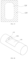
- the recess 140 has a bottom surface 140a and a side surface surrounding the bottom surface 140a.
- the side face includes a side surface 140b, a side surface 140c, a side surface 140d and a side surface 140e.
- the side surface 140b and the side surface 140e are axially opposite, and the side surface 140c and the side surface 140d are radially opposite.
- the bottom surface 140a is a plane or a curved surface.
- the curved surface can be a concave surface downwards recessed with respect to an opening of the recess 140, a convex surface upwards bulged with respect to the opening of the recess 140, or a curved surface with both a concave portion and a convex portion.
- the second stent 120 is at least partially accommodated in the recess 140, and a longitudinal central axis I-I of the first stent 110 is parallel or substantially parallel to a longitudinal central axis II-II of the second stent 120.
- Being substantially parallel means that an angle between the longitudinal central axis I-I and the longitudinal central axis II-II is greater than 0° and less than 10°.
- the first stent 110 and the second stent 120 are made of materials with good biocompatibility and good elasticity, such as nickel-titanium alloy and stainless steel.
- the covering membrane 130 is made of a highly biocompatible film material, such as PET and PTFE.
- the way for combining or fixing the covering membrane 130 and the first stent 110 is not limited, for example, high temperature pressurization or suture fixation can also be used.
- the covering membrane 130 can be of a single-layer structure or a multilayer structure.
- the second stent 120 is completely accommodated in the recess 140. Furthermore, an outer surface of the second stent 120 far away from the bottom surface 140a of the recess 140 is flush with an outer surface of the first stent 110. As shown in Fig. 1 , that is, the second stent 120 and the first stent 110 are coplanar in a section of the recess 140 in an opening direction (the section is parallel to the longitudinal central axis I-I and the longitudinal central axis II-II). The entire membrane-covered stent 100 has a uniform outer diameter.
- an outer surface of the second stent 120 far away from the bottom surface 140a of the recess 140 is lower than an open end of the recess 140, that is, an outer diameter of the second stent 120 is less than a depth of the recess 140.
- a difference value between the outer diameter of the second stent 120 and the depth of the recess 140 does not exceed 25% of the outer diameter of the second stent 120, so as to avoid such a phenomenon that an extremely deep recess 140 blocks a main body vessel to affect the blood flow of the main body vessel.
- the second stent 120 is partially accommodated in the recess 140, that is, the second stent 120 partially protrudes from the recess 140.
- a distance between the projecting portion and the end surface of the open end of the recess 140 shall not exceed 10% of the outer diameter of the second stent 120, so as to avoid affecting the anchoring of the first stent 110 of the membrane-covered stent 100 and the main body vessel, or avoid the second stent 120 from excessively pressing a vascular wall to damage the vascular wall.
- the first stent 110 has a first end 110A and a second end 110B axially opposite to each other.
- the first stent 110 includes a plurality of first waveform rings 112 and at least one second waveform ring 114.
- the plurality of first waveform rings 112 are located at the first end 110A and the second end 110B of the first stent 110.
- the at least one second waveform ring 114 is located between the first waveform rings 112 at both ends, and is radially opposite to the recess 140. That is, the second waveform ring 114 is located in the middle portion of the first stent 110.
- each first waveform ring 112 is of a Z-shaped waveform ring structure.
- the Z-shaped waveform ring structure is of a closed-loop structure with wave crests and wave troughs and formed by connecting a plurality of first wave rods (not shown in the figure) end to end.
- At least one first waveform ring 112 is located at the first end 110A, and at least one first waveform ring 112 is located at the second end 110B.
- two or more first waveform rings 112 are located at the first end 110A, and two or more first waveform rings 112 are located at the second end 110B.
- two or more first waveform rings 112 at each end are arranged at intervals along an axial direction (an extending direction of the longitudinal central axis I-I).
- two or more first waveform rings 112 at each end are connected by axial connectors (not shown in the figure) or the plurality of first waveform rings 112 are connected together by the covering membrane 130 without any connectors.
- the number of the first waveform ring 112 located at the first end 110A and the number of the first waveform ring 112 located at the second end 110B can be equal or unequal.
- the waveforms, wave heights, wave numbers, etc. of the plurality of waveform rings 112 located on both sides of the second waveform ring 114 can be the same or different.
- the number of the first waveform ring 112 located on both sides of the second waveform ring 114 may be equal or unequal.
- a radial dimension (a distance between two points farthest from each other, the same below, for example, a diameter) of the second waveform ring 114 is less than a radial dimension (for example, a diameter) of the first waveform ring 112, so that when the covering membrane 130 is covered on the first stent 110 to form a lumen structure with two open ends and the recess 140 in the middle portion.
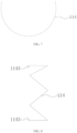
- the second waveform ring 114 is of a closed-loop structure with wave crests and wave troughs and formed by connecting a plurality of second wave rods (not shown in the figure) end to end, as shown in Fig. 3 , but the diameter of the second waveform ring 114 is less than that of the first waveform ring 112.
- the second waveform ring 114 is opposite to the bottom surface 140a of the recess 140, and radially supports a region of the covering membrane 130 located on the bottom surface 140a.
- the second waveform ring 114 is fixedly connected with the region of the covering membrane 130 located on the bottom surface 140a.
- the second waveform ring 114 is fixedly connected with at least one of portions of the covering membrane 130 located on the side surface 140b, the side surface 140c, the side surface 140d and the side surface 140e, but is not connected with a portion of the covering membrane 130 located on the bottom surface 140a.
- the connection way includes but is not limited to direct fixed connection by means of gluing and suturing.
- the second waveform ring 114 and the covering membrane 130 are indirectly connected by a connector.
- the second waveform ring 114 is of a closed-loop structure, including a first non-closed waveform ring 1142 and a first closed portion 1144.
- the first non-closed waveform ring 1142 is of a non-closed structure with wave crests and troughs and formed by connecting a plurality of wave rods (not shown in the figure) end to end, with end portions not connected.
- the first non-closed waveform ring 1142 is 1/2 to 3/4 of a circular structure.
- the first non-closed loop 1142 is 5/9 to 8/9 of a circle.
- a non-closed waveform ring 1142 is 1/4 to 5/9 of a circle.
- the two ends of the first closed portion 1144 are respectively connected with the two free ends of the first non-closed loop 1142 to form the closed-loop structure.
- the first closed portion 1144 is of a rod piece structure, including a straight rod 1144A.
- the straight rod 1144A is opposite to the bottom surface 140a.
- the straight rod 1144A of the second waveform ring 114 of this structure has a planar region, which can be well matched with the bottom surface 140a of the recess 140, so as to better radially support the region of the covering member 130 located on the bottom surface 140a and facilitate maintaining the bottom surface 140a of the recess 140 as a plane or substantially as a plane, thus helping to maintain the shape of the recess 140, and avoiding such a phenomenon that the blood flow of the branch vessel is blocked since the recess 140 deforms to make the region of the covering member 130 located on the recess 140 fitted to the opening of the branch vessel.
- the second waveform ring 114 is fixedly connected, through the straight rod 1144A, with the region of the covering membrane 130 located on the bottom surface 140a.
- the second waveform ring can also be fixedly connected with an inner surface of the covering membrane 130 through other portions, while the straight rod 1144A is not fixedly connected with the region of the covering membrane 130 located on the bottom surface 140a, that is, the recess 140 only overlaps the straight rod 1144A of the second waveform ring 114, and is not fixed by gluing, suturing and the like.
- the first closed portion 1144 also includes two arc-shaped rods 1144B which are respectively connected with the two ends of the straight rod 1144A, and ends of the two arc-shaped rods 1144B far away from the straight rod 1144A are respectively connected with the two free ends of the first non-closed loop 1142.
- the arc-shaped rods 1144B are arranged to form a transition and avoid stress concentration, so as to avoid the risk of fracture of a connection portion between the first closed portion 1144 and the first non-closed waveform ring 1142.
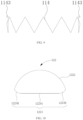
- the first closed portion 1144 is omitted, that is, the second waveform ring 114 only includes the first non-closed waveform ring 1142, so that the second waveform ring 114 is of a non-closed loop structure, as shown in Fig. 7 .
- the two free ends of the second waveform ring 114 are of a passivated structure to avoid puncturing the covering membrane 130.
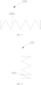
- the two free ends of the second waveform ring 114 curl respectively in a inwards direction or an outwards direction to form two passivated structures 1143.
- the passivated structure can be in other ways, such as a spherical structure fixed to the free ends of the second waveform ring 114 by welding or in other fixing manners.
- the second stent 120 includes at least one third waveform ring 122.
- there are a plurality of third waveform rings 122 and the plurality of the third waveform rings 122 are arranged in the recess 140 at intervals along the longitudinal central axis II-II.
- the plurality of third waveform rings 122 are arranged in the recess 140 in a non-spaced manner along the longitudinal central axis II-II.
- the third waveform ring 122 is of a closed loop structure.
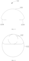
- the third waveform ring 122 includes a second non-closed waveform ring 1222 and a second closed portion 1224.
- the second non-closed waveform ring 1222 is of a non-closed loop structure formed by connecting a plurality of wave rods 1222a end to end, with end portions not connected, so that the second non-closed waveform ring 1222 has two free ends.
- the second non-closed waveform ring 1222 is 1/2 to 3/4 of a circular structure.
- the second closed portion 1224 includes a straight connecting rod 1224A and two arc-shaped transitional rods 1224B respectively connected with two ends of the straight connecting rod 1224A. Two ends of the two arc-shaped transitional rods 1224B are respectively connected with the two free ends of the second non-closed waveform ring 1222, thus forming the closed-loop third waveform ring 122.
- the third waveform ring 122 is accommodated in the recess 140, and the second closed portion 1224 of the third waveform ring 122 is arranged on the bottom surface 140a of the recess 140. More specifically, the straight connecting rod 1224A of the second closed portion 1224 is arranged on the bottom surface 140a of the recess 140.
- the radian of the second non-closed waveform ring 1222 matches the radian of the first waveform ring 112 of the first stent 110, so that the outline of the membrane-covered stent 100 is a hollow or substantially hollow cylindrical structure.
- the third waveform ring 122 includes the second non-closed waveform ring 1222 and the second closed portion 1224, the third waveform ring can not only match the shape of the recess 140, but also match the radian of the first waveform ring 112, so as to provide a better radial support for the recess 140, and enable the external outline of the membrane-covered stent 100 to be smoothly transitioned, so that the outline of the membrane-covered stent 100 is of a hollow or substantially hollow cylindrical structure to facilitate delivery and release.
- the third waveform ring 122 is fixed on the side surface 140d through the wave rods 1222a, so that the third waveform ring 122 is fixed in the recess 140.
- one wave rod 1222a of the third waveform ring 122 is fixedly connected with an edge line of the side surface 140d
- the other wave rod 1222a of the third waveform ring 112 is fixedly connected with an edge line of the side surface 140c.
- the straight connecting rod 1224A is omitted, that is, the third waveform ring 122 includes a second non-closed waveform ring 1222 and two arc-shaped transitional rods 1224B respectively connected with two free ends of the second non-closed waveform ring 1222, so that the third waveform ring 122 has an opening and is of a non-closed loop structure.
- the wave rods 1222a of the third waveform ring 122 are fixedly connected with the edge lines of the side surfaces 140d and 140c to fix the third waveform ring 122 in the recess 140.
- the wave rods 1222a of the third waveform ring 122 is connected with the side surface 140d and the side surface 140c to fix the third waveform ring 122 in the recess 140, but the connection portion is not necessarily located on the edge lines of the side surface 140d and the side surface 140c.
- the straight connecting rod 1224A is conducive to reducing the consumption of metals.
- the second non-closed waveform ring 1222 of the third waveform ring 122 can press the bottom surface 140a of the recess 140 to prevent the bottom surface 140 of the recess 140d from being fitted to the opening of the branch vessel.
- a free end of each arc-shaped transitional rod 1224B is of a passivated structure to avoid damaging the covering membrane 130.
- the form of the passivated structure is not limited.
- the passivated structure can be the same as the passivated structure of the second waveform ring 114. It will not be repeated here.
- the third waveform ring 122 is of a closed-loop structure with wave crests and wave troughs and formed by connecting a plurality of wave rods end to end, that is, the third waveform ring 112 is a cylindrical waveform ring. a contact area between the cylindrical third waveform ring 122 and the bottom surface 140a of the recess 140 is small, which is conducive to the subsequent windowing operation.
- the cylindrical third waveform ring 122 is fixedly connected with the side surface 140c and the side surface 140d of the recess 140 by means of the wave rods which are radially opposite, and a bottom portion of the third waveform ring 122 is not connected with the bottom surface 140a of the recess 140.
- the plurality of third waveform rings 122 are arranged along the axial direction (the extending direction of the longitudinal central axis II-II) at intervals. Adjacent third waveform rings 122 can be connected through an axial connector (not shown in the figure), and may not be connected. Arranging the axial connector can stabilize the release position of the third waveform ring 122.
- the axial connector can be a rigid connector or a flexible connector.
- the third waveform rings 122 can be connected by an axial connector 124.
- the axial connector 124 is a straight rodlike rigid connector. Furthermore, when the membrane-covered stent 100 is bent, a large curvature side and a small curvature side are formed. The axial connector 124 is located at the large curvature side, so as not to affect the bending of the membrane-covered stent 100. In one embodiment, the number of the axial connector 124 does not exceed two. In one embodiment, the number of the axial connector 124 is 1, that is, only one axial connector 124 is used to connect two adjacent third waveform rings 122.
- the axial connector 124 is a flexible connector.
- the position and number of the flexible connector are not limited.
- the number of the flexible connector is three, and the three flexible connectors are located on one side of the second stent 120 far away from the bottom surface 140a of the recess 140.
- the second stent 120 is an integrated metal skeleton.
- the second stent 120 is a lumen net structure formed by braiding metal wires or cutting a metal tube.
- the second stent 120 includes a plurality of third waveform rings 122 (not shown in Fig. 17 ) arranged in a non-spaced manner, and the wave crests and wave troughs of two adjacent third waveform rings 122 are axially opposite and connected, so that the wave crests and wave troughs of each third waveform ring 122 are no longer in a state with free ends.
- the second stent 120 of this structure is of an integrated structure, which can avoid such a phenomenon that the free ends of the wave crest and/or wave trough of a single waveform ring can be easily pushed into the branch vessel, thus avoiding the damage to the branch vessels caused by the single waveform ring, and improving the safety of use.
- the bottom portion of the second stent 120 is connected with the bottom surface 140a of the recess 140.
- side surfaces of the second stent 120 are connected with the side surface 140c and the side surface 140d of the recess 140.
- the second stent 120 is connected with the covering membrane 130 or the first waveform ring 112 through an axial connecting rod 150.
- One end of the axial connecting rod 150 is connected with a first end of the second stent 120, and the other end extends axially out of the recess 140 and is connected with the covering membrane 130 or the first waveform ring 112.
- each axial connecting rod 150 is connected with the second stent 120, and the other end extends axially from the open end of the recess 140 to the outside of the recess 140a, and is connected with the covering membrane 130 or the first waveform ring 112.
- the bottom portion (a portion close to the bottom surface 140a of the recess 140) of the second stent 120 is not fixedly connected with the bottom surface 140a of the recess 140, so as to facilitate the adjustment of the relative position between the bottom portion of the second stent 120 and the bottom surface 140a of the recess 140, and facilitate the subsequent windowing and branch stent implanting operations.
- the form of the axial connecting rod 150 is not limited.
- it can be a straight rod, a specially-shaped rod, or the like.
- the shape of a cross section of the second stent 120 is not limited.
- the second stent can be of the structure shown in Fig. 10 that includes the second non-closed waveform ring 1222, the straight connecting rod 1224A and the arc-shaped transitional rods 1224B, or can be of the structure shown in Fig. 13 that includes the second non-closed waveform ring 1222 and the arc-shaped transitional rods 1224B, but the straight connecting rod 1224A is omitted.
- the second stent can also be of a cylindrical structure as shown in Fig. 14 , which will not be described repeatedly in detail here.
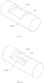
- a first window 124 is formed in the bottom portion (the portion close to the bottom surface 140a of the recess 140) of the second stent 120.
- the first window 124 is located in a middle region of the second stent 120. Since the window 124 is not blocked or interfered by the metal skeleton partially, the subsequent windowing and branch stent implanting operations are easier. In addition, it is beneficial to reduce the use of metals. At the same time, since the radial dimension of the compressed second stent 120 is reduced, the radial dimension of the compressed membrane-covered stent 100 is reduced, so that a smaller delivery sheath can be used for delivery, causing less injury to patients or being applicable for more patients.
- a second window 126 is also arranged at a portion of the second stent 120 radially opposite to the first window 124, and the first window 124 is opposite to the second window 126, that is, the middle region of the second stent 120 is not provided with the metal skeleton.
- the metal skeleton at the edges of the second window 124 and the second window 126 is used for supporting, so that after the membrane-covered stent 100 is implanted into a blood vessel, the metal skeleton presses the bottom surface 140a of the recess 140 to prevent the bottom surface 140a of the recess 140 from moving towards the opening of a branch vessel and being fitted to the opening of the branch vessel.
- the dosage of metal is smaller, and the radial dimension of the compressed membrane-covered stent 100 is smaller, so that a smaller delivery sheath can be used for delivery, causing less injury to patients, or being applicable to more patients.
- the first window 124 is formed in the bottom portion of the second stent 120, or the first window 124 can be formed in a side (i.e. a top portion of the second stent 120) of the second stent 120 opposite to the bottom portion.
- the recess 140 is provided with a through hole running through a side surface of the recess 140 to allow the blood flow to pass.
- at least one of the bottom surface 140a, the side surface 140b, the side surface 140c, the side surface 140d and the side surface 140e of the recess 140 is provided with a through hole.
- the recess 140 is provided with a first through hole 142 running through the side surface 140b. The blood flow can flow from the main body vessel to each branch vessel through the first through hole 142. When the lesion does not involve the root of the branch artery, there is no need to implant a branch stent later, which is more economical for patients.
- the first through hole 142 and the first window 124 can be used as a channel for aa branch stent.
- the branch stent enters the second stent 120 from the first through hole 142, and extends out of the second stent 120 from the first window 124.
- the recess 140 is provided with a second through hole 144 running through the side surface 140e, which can also realize that the blood flow flows from the main body vessel to each branch vessel through the second through hole 144.
- the lesion does not involve the root of the branch artery, there is no need to implant a branch stent later.
- first through hole 142 and the second through hole 144 can exist at the same time, or either the first through hole 142 or the second through hole 144 can exist.
- the recess 140 is provided with a third through hole 146 running through the bottom portion 140a, which can also realize that the blood flow can flow from the main body vessel to each branch vessel through the third through hole 146.
- a third through hole 146 running through the bottom portion 140a, which can also realize that the blood flow can flow from the main body vessel to each branch vessel through the third through hole 146.
- the third through hole 146 when there is the third through hole 146, at least one of the first through hole 142 and the second through hole 144 can be omitted, or both can be maintained.
- first through hole 142 the second through hole 144 and the third through hole 146 are not limited, as long as the blood flow can pass and will not adversely affect the overall structure of the recess 140.
- first through hole 142, the second through hole 144 and the third through hole 146 are all round holes. In addition, there is one first through hole 142, one second through hole 144, and three third through holes 146.
- a diseased vessel 1 is the aortic arch vessel, and one side of the arch opposite to a branch vessel has an arterial dissection 2.
- the recess 140 corresponds to the branch vessel.
- three branch vessels 101 are radially opposite to the recess 140.
- the second stent 120 can provide a reverse supporting force for the bottom surface 140a of the recess 140 to restrain the trend of the bottom surface 140a of the recess 140 for protruding towards the branch vessels 101, so that the bottom surface 140a of the recess 140 can be far away from the openings of the branch vessels 101, so as to prevent the covering membrane 130 from blocking the openings of the branch vessels 101.
- an in situ windowing technology is used to form a window running through the bottom surface 140a (not shown in Fig. 23 ) of the recess 140.
- the branch stent 200 is delivered into the branch vessel 101 from the window and is released to establish a blood flow channel between the branch vessel 101 and the diseased vessel 1.
- the shape of the recess 140 can be well maintained, so that the bottom surface 140a of the recess 140 can keep a sufficient distance from the opening of the branch vessel 101, so as to facilitate in situ windowing and implantation of the branch stent 200.
- the position of the third waveform ring 122 can be adjusted according to a requirement, so that the operations are more convenient, which is conductive to improving the position accuracy and shortening the operation time.
- the third waveform ring 122 is fixed around the branch stent 200 to form a stable support, maintain the stability of the position of the branch stent 200, and keep the branch vessels continuously unblocked.
- second waveform rings 114 and the third waveform rings 122 of different embodiments are respectively described above.
- the second waveform rings 114 and the third waveform rings 122 of different embodiments can be combined arbitrarily.
- the second waveform ring 114 shown in Fig. 7 can be combined with the third waveform ring 122 shown in Fig. 10 .
- the straight connecting rod 1224A of the third waveform ring well matches with the bottom surface 140a of the recess 140, which can better press the bottom surface 140a of the recess 140 and prevent the bottom surface 140a from being fitted to the openings of the branch vessels.
- the second waveform ring 114 is of an open structure, which is conducive to reducing the dosage of metal and reducing the radial dimension of the compressed membrane-covered stent 100.
- the second waveform ring 114 shown in Fig. 4 can be combined with the third waveform ring 122 shown in Fig. 10 , so that the straight rod 1144A of the second waveform ring 114 and the straight connecting rod 1224A of the third waveform ring 122 are opposite and cooperate with each other.
- the second waveform ring 114 shown in Fig. 7 can be combined with the third waveform ring 122 shown in Fig. 13 , and the third waveform ring 122 applies a radial supporting force to the recess 140 through the second non-closed waveform ring 1222.
- This combination uses less metal.
- the second waveform ring 114 shown in Fig. 7 can be combined with the third waveform ring 122 shown in Fig. 14 , and the third waveform ring 122 applies a radial supporting force to the recess 140 through the second non-closed waveform ring 1222.
- the second waveform ring 114 shown in Fig. 7 can be combined with the second stent 120 shown in Fig. 17 to provide a radial supporting force for the recess 140 through the second stent 120.
- the second stent 120 of this structure can avoid the risk of damaging an inner wall of a branch vessel by the third waveform ring 122 with the free ends at the end portions.
- the second waveform ring 114 shown in Fig. 7 can be combined with the third waveform ring 122 shown in Fig. 18 or Fig. 19 .
- the second waveform ring 114 shown in Embodiment 4 can be combined with the third waveform ring 122 shown in Fig. 13 .
- the straight rod 1144A of the second waveform ring 114 presses the bottom surface 140a of the recess 140, and the dosage of metal is reduced, that is, the radial dimension of the compressed membrane-covered stent 100 is reduced.
- the radial supporting strength P1 of the first stent 110 and the radial supporting strength P2 of the second stent 120 are different.
- P1 and P2 satisfy: 1/2 ⁇ (P2/P1) ⁇ 1, that is, the radial supporting strength P2 of the second stent 120 is less than the radial supporting strength P1 of the first stent 110, but P2 should be high enough, greater than 0.5 times of P1, so that when the first stent 110 and the second stent 120 are subjected to the same radial compression force, a decrease of the radial dimension of the second stent 120 after the radial compression is not too large, so as to facilitate the windowing operation.
- P1 and P2 satisfy: 1 ⁇ (P2/P1) ⁇ 2, that is, the radial supporting strength P2 of the second stent 120 is greater than or equal to the radial supporting strength P1 of the first stent 110, and P2 is less than twice P1, so that when the first stent 110 and the second stent 120 are subjected to the same radial compression force, a decrease of the radial dimension of the first stent 110 after the radial compression is not too large, so as to keep the blood flow through the first stent 110 unblocked.
- a radial supporting strength is equal to a ratio of a radial supporting force to an axial length.
- P2 F2/L2.
- a plate compression method can be used to test the radial supporting force F 1 of the first stent 110 and the radial supporting force F2 of the second stent 120.
- a radial compression method can be used to test the radial supporting force F1 of the first stent 110 and the radial supporting force F2 of the second stent 120. That is, to compare F1 with F2, F1 and F2 are tested using the same test method under the same conditions.
- the radial compression method is used to test the radial supporting force F1 when the first stent 110 is compressed by 50% and the radial supporting force F2 when the second stent 120 is compressed by 50%.
- two flat plates compress both sides of a stent respectively.
- the two flat plates are parallel and are symmetrically arranged about the axis of symmetry of the longitudinal central axis.
- the two flat plates are respectively two tangent planes of the stent.
- the radial supporting force F1 of the first stent 110 is related to a rod diameter, wave number, included angle at the wave trough or wave crest and other parameters of the second waveform ring 114
- the radial supporting force F2 of the second stent 120 is related to a rod diameter, wave number, included angle at the wave trough or wave crest of the third waveform ring 122, which can be adjusted by those skilled in the art as required.
- the membrane-covered stent 100 also includes an anchorage stent 160.
- the anchorage stent 160 is located at a first end 110A of the first stent 110 and is connected to the first waveform ring 112 or the covering membrane 130.
- the anchorage stent 160 is a bare stent, excluding any covering membrane.
- the anchorage stent 160 includes at least one anchorage waveform ring 162. When there are a plurality of anchorage waveform rings 162, the plurality of anchorage waveform rings 162 are arranged at intervals along the longitudinal central axis I-I.
- the anchorage stent 160 When the membrane-covered stent 100 is implanted into a blood vessel, the anchorage stent 160 is located at the proximal end of the membrane-covered stent 100. The anchorage stent 160 is arranged to further improve the anchorage performance of an end portion of the membrane-covered stent 100.
- one first waveform ring 110 is located at the first end 110A.
- one first waveform ring 110 cooperates with the anchorage stent 160 to achieve the anchorage of the proximal end of the membrane-covered stent 100.
- the anchorage stent 160 is a bare stent, it will not completely cover the opening of the third branch vessel 101, so there is no need to form a window and implant a branch stent 200.
- a length of a wave rod of the anchorage waveform ring 162 is less than a length of the wave rod of the first waveform ring 110, and the wave number of the anchorage waveform ring 162 is greater than the wave number of the first waveform ring 110, so that the anchorage performance of the anchorage stent 160 is better.
Landscapes
- Health & Medical Sciences (AREA)
- Engineering & Computer Science (AREA)
- Biomedical Technology (AREA)
- Cardiology (AREA)
- Oral & Maxillofacial Surgery (AREA)
- Transplantation (AREA)
- Heart & Thoracic Surgery (AREA)
- Vascular Medicine (AREA)
- Life Sciences & Earth Sciences (AREA)
- Animal Behavior & Ethology (AREA)
- General Health & Medical Sciences (AREA)
- Public Health (AREA)
- Veterinary Medicine (AREA)
- Gastroenterology & Hepatology (AREA)
- Pulmonology (AREA)
- Prostheses (AREA)
Applications Claiming Priority (2)
| Application Number | Priority Date | Filing Date | Title |
|---|---|---|---|
| CN202011397340.4A CN114569303B (zh) | 2020-12-02 | 2020-12-02 | 覆膜支架 |
| PCT/CN2021/125251 WO2022116727A1 (zh) | 2020-12-02 | 2021-10-21 | 覆膜支架 |
Publications (2)
| Publication Number | Publication Date |
|---|---|
| EP4257094A1 true EP4257094A1 (de) | 2023-10-11 |
| EP4257094A4 EP4257094A4 (de) | 2024-10-23 |
Family
ID=81770579
Family Applications (1)
| Application Number | Title | Priority Date | Filing Date |
|---|---|---|---|
| EP21899761.7A Pending EP4257094A4 (de) | 2020-12-02 | 2021-10-21 | Stent mit membranabdeckung |
Country Status (4)
| Country | Link |
|---|---|
| US (1) | US20230414339A1 (de) |
| EP (1) | EP4257094A4 (de) |
| CN (2) | CN120605130A (de) |
| WO (1) | WO2022116727A1 (de) |
Families Citing this family (8)
| Publication number | Priority date | Publication date | Assignee | Title |
|---|---|---|---|---|
| EP4458327A4 (de) * | 2021-12-31 | 2025-04-30 | Lifetech Scientific (Shenzhen) Co., Ltd. | Lumenstent |
| CN115177400B (zh) * | 2022-06-28 | 2025-06-06 | 杭州创心医学科技有限公司 | 一种覆膜支架 |
| CN118267203B (zh) * | 2022-12-29 | 2025-07-08 | 先健科技(深圳)有限公司 | 管腔支架 |
| CN118267207B (zh) * | 2022-12-29 | 2025-12-02 | 先健科技(深圳)有限公司 | 管腔支架 |
| CN116370144A (zh) * | 2023-05-19 | 2023-07-04 | 杭州唯强医疗科技有限公司 | 血管支架及系统 |
| CN119257808B (zh) * | 2023-07-06 | 2026-01-02 | 中国医学科学院阜外医院 | 血管支架 |
| WO2025119133A1 (zh) * | 2023-12-04 | 2025-06-12 | 先健科技(深圳)有限公司 | 凹槽支架及其制作方法 |
| CN120227189B (zh) * | 2023-12-28 | 2026-03-13 | 先健科技(深圳)有限公司 | 覆膜支架 |
Family Cites Families (15)
| Publication number | Priority date | Publication date | Assignee | Title |
|---|---|---|---|---|
| US8167926B2 (en) * | 2006-11-07 | 2012-05-01 | Cook Medical Technologies Llc | Fenestration for stent graft arrangements and stent graft including the same |
| EP2194919A4 (de) * | 2007-09-26 | 2013-05-08 | Trivascular Inc | Vorrichtung und verfahren zur stentausrichtung |
| AU2010254599B1 (en) * | 2010-12-15 | 2011-02-17 | Cook Incorporated | Hybrid Type A dissection device |
| US9668892B2 (en) * | 2013-03-11 | 2017-06-06 | Endospan Ltd. | Multi-component stent-graft system for aortic dissections |
| EP3003230B1 (de) * | 2013-06-05 | 2018-07-25 | Aortic Innovations Surena, LLC | Stens mit variablen vertiefungen (vds) und sich aufblähenden transplantatanordnungen |
| CN103720529B (zh) * | 2013-12-30 | 2017-02-08 | 先健科技(深圳)有限公司 | 主动脉弓术中支架及该支架的制造方法 |
| JP6363292B2 (ja) * | 2014-09-10 | 2018-07-25 | ザ クリーブランド クリニック ファウンデーションThe Cleveland ClinicFoundation | フレーム構造 |
| WO2016048239A1 (en) * | 2014-09-22 | 2016-03-31 | National University Of Singapore | Stent graft device |
| CN106923931B (zh) * | 2015-12-31 | 2019-12-10 | 先健科技(深圳)有限公司 | 覆膜支架 |
| CN106923943B (zh) * | 2015-12-31 | 2019-12-10 | 先健科技(深圳)有限公司 | 覆膜支架 |
| JP6986522B2 (ja) * | 2016-05-25 | 2021-12-22 | ボルトン メディカル インコーポレイテッド | ステントグラフト |
| CN114831786A (zh) * | 2016-12-31 | 2022-08-02 | 元心科技(深圳)有限公司 | 可吸收支架 |
| CN109938895B (zh) * | 2017-12-20 | 2024-02-06 | 杭州唯强医疗科技有限公司 | 开窗型覆膜支架 |
| JP7434683B2 (ja) * | 2018-09-27 | 2024-02-21 | Sbカワスミ株式会社 | ステントグラフト |
| CN111035470B (zh) * | 2018-10-12 | 2022-05-10 | 先健科技(深圳)有限公司 | 覆膜支架组件及管腔支架 |
-
2020
- 2020-12-02 CN CN202510628276.2A patent/CN120605130A/zh active Pending
- 2020-12-02 CN CN202011397340.4A patent/CN114569303B/zh active Active
-
2021
- 2021-10-21 US US18/038,948 patent/US20230414339A1/en active Pending
- 2021-10-21 WO PCT/CN2021/125251 patent/WO2022116727A1/zh not_active Ceased
- 2021-10-21 EP EP21899761.7A patent/EP4257094A4/de active Pending
Also Published As
| Publication number | Publication date |
|---|---|
| EP4257094A4 (de) | 2024-10-23 |
| US20230414339A1 (en) | 2023-12-28 |
| CN114569303B (zh) | 2025-06-03 |
| CN114569303A (zh) | 2022-06-03 |
| CN120605130A (zh) | 2025-09-09 |
| WO2022116727A1 (zh) | 2022-06-09 |
Similar Documents
| Publication | Publication Date | Title |
|---|---|---|
| EP4257094A1 (de) | Stent mit membranabdeckung | |
| WO2021219074A1 (zh) | 覆膜支架 | |
| JP4783876B2 (ja) | ステントグラフト、ステントグラフトデリバリー(送入)システムおよびキット、およびステントグラフトを留置する方法 | |
| US11478235B2 (en) | Closure apparatus with flexible sealable member and flexible support member | |
| JP5667544B2 (ja) | ステントグラフトの近位端部を自動的に中心に配置する送達システム及び方法 | |
| KR102080072B1 (ko) | 탈분지 내장 스텐트 그래프트 및 이의 사용방법 | |
| US11701216B2 (en) | Stent to assist in arteriovenous fistula formation | |
| EP3977961B1 (de) | Gefässrekonstruktionsvorrichtung | |
| CN118490412A (zh) | 血管支架、支架系统及输送系统 | |
| CN102014805A (zh) | 覆膜支架输送系统的双捕捉装置和覆膜支架捕捉法 | |
| CN219439576U (zh) | 一种覆膜支架 | |
| CN110693635B (zh) | 管腔支架输送器 | |
| CN109938895A (zh) | 开窗型覆膜支架 | |
| JP2022525788A (ja) | 大動脈解離インプラント | |
| CN206414369U (zh) | 一种带分支支架血管的主动脉弓直视支架血管 | |
| EP3988062A1 (de) | Segmentierter abgedeckter stent und verfahren zu seiner herstellung | |
| CN118902684A (zh) | 一种覆膜支架及其释放装置 | |
| CN215606578U (zh) | 主动脉弓部覆膜支架 | |
| EP4205701A1 (de) | Abgedeckter stent | |
| CN119896559A (zh) | 人工血管支撑环及人工血管支撑环系统 | |
| CN220360478U (zh) | 支架系统 | |
| CN112472381A (zh) | 支架 | |
| CN112472380A (zh) | 覆膜支架 | |
| CN121398756A (zh) | 主动脉瘤吻合装置 | |
| CN118267150A (zh) | 覆膜支架 |
Legal Events
| Date | Code | Title | Description |
|---|---|---|---|
| STAA | Information on the status of an ep patent application or granted ep patent |
Free format text: STATUS: THE INTERNATIONAL PUBLICATION HAS BEEN MADE |
|
| PUAI | Public reference made under article 153(3) epc to a published international application that has entered the european phase |
Free format text: ORIGINAL CODE: 0009012 |
|
| STAA | Information on the status of an ep patent application or granted ep patent |
Free format text: STATUS: REQUEST FOR EXAMINATION WAS MADE |
|
| 17P | Request for examination filed |
Effective date: 20230606 |
|
| AK | Designated contracting states |
Kind code of ref document: A1 Designated state(s): AL AT BE BG CH CY CZ DE DK EE ES FI FR GB GR HR HU IE IS IT LI LT LU LV MC MK MT NL NO PL PT RO RS SE SI SK SM TR |
|
| DAV | Request for validation of the european patent (deleted) | ||
| DAX | Request for extension of the european patent (deleted) | ||
| REG | Reference to a national code |
Ref country code: DE Ref legal event code: R079 Free format text: PREVIOUS MAIN CLASS: A61F0002890000 Ipc: A61F0002070000 |
|
| A4 | Supplementary search report drawn up and despatched |
Effective date: 20240919 |
|
| RIC1 | Information provided on ipc code assigned before grant |
Ipc: A61F 2/89 20130101ALN20240913BHEP Ipc: A61F 2/06 20130101ALN20240913BHEP Ipc: A61F 2/852 20130101ALN20240913BHEP Ipc: A61F 2/07 20130101AFI20240913BHEP |