EP4257208A1 - Procédé et frein d'ergomètre destiné au changement dynamique dépendant de la force de la force de freinage d'un appareil d'entrainement - Google Patents
Procédé et frein d'ergomètre destiné au changement dynamique dépendant de la force de la force de freinage d'un appareil d'entrainement Download PDFInfo
- Publication number
- EP4257208A1 EP4257208A1 EP22166910.4A EP22166910A EP4257208A1 EP 4257208 A1 EP4257208 A1 EP 4257208A1 EP 22166910 A EP22166910 A EP 22166910A EP 4257208 A1 EP4257208 A1 EP 4257208A1
- Authority
- EP
- European Patent Office
- Prior art keywords
- force
- flywheel
- permanent magnets
- ergometer
- lever
- Prior art date
- Legal status (The legal status is an assumption and is not a legal conclusion. Google has not performed a legal analysis and makes no representation as to the accuracy of the status listed.)
- Granted
Links
Images


Classifications
-
- A—HUMAN NECESSITIES
- A63—SPORTS; GAMES; AMUSEMENTS
- A63B—APPARATUS FOR PHYSICAL TRAINING, GYMNASTICS, SWIMMING, CLIMBING, OR FENCING; BALL GAMES; TRAINING EQUIPMENT
- A63B21/00—Exercising apparatus for developing or strengthening the muscles or joints of the body by working against a counterforce, with or without measuring devices
- A63B21/005—Exercising apparatus for developing or strengthening the muscles or joints of the body by working against a counterforce, with or without measuring devices using electromagnetic or electric force-resisters
- A63B21/0051—Exercising apparatus for developing or strengthening the muscles or joints of the body by working against a counterforce, with or without measuring devices using electromagnetic or electric force-resisters using eddy currents induced in moved elements, e.g. by permanent magnets
-
- A—HUMAN NECESSITIES
- A63—SPORTS; GAMES; AMUSEMENTS
- A63B—APPARATUS FOR PHYSICAL TRAINING, GYMNASTICS, SWIMMING, CLIMBING, OR FENCING; BALL GAMES; TRAINING EQUIPMENT
- A63B21/00—Exercising apparatus for developing or strengthening the muscles or joints of the body by working against a counterforce, with or without measuring devices
- A63B21/005—Exercising apparatus for developing or strengthening the muscles or joints of the body by working against a counterforce, with or without measuring devices using electromagnetic or electric force-resisters
- A63B21/0058—Exercising apparatus for developing or strengthening the muscles or joints of the body by working against a counterforce, with or without measuring devices using electromagnetic or electric force-resisters using motors
- A63B21/0059—Exercising apparatus for developing or strengthening the muscles or joints of the body by working against a counterforce, with or without measuring devices using electromagnetic or electric force-resisters using motors using a frequency controlled AC motor
-
- A—HUMAN NECESSITIES
- A63—SPORTS; GAMES; AMUSEMENTS
- A63B—APPARATUS FOR PHYSICAL TRAINING, GYMNASTICS, SWIMMING, CLIMBING, OR FENCING; BALL GAMES; TRAINING EQUIPMENT
- A63B21/00—Exercising apparatus for developing or strengthening the muscles or joints of the body by working against a counterforce, with or without measuring devices
- A63B21/02—Exercising apparatus for developing or strengthening the muscles or joints of the body by working against a counterforce, with or without measuring devices using resilient force-resisters
- A63B21/023—Wound springs
-
- A—HUMAN NECESSITIES
- A63—SPORTS; GAMES; AMUSEMENTS
- A63B—APPARATUS FOR PHYSICAL TRAINING, GYMNASTICS, SWIMMING, CLIMBING, OR FENCING; BALL GAMES; TRAINING EQUIPMENT
- A63B21/00—Exercising apparatus for developing or strengthening the muscles or joints of the body by working against a counterforce, with or without measuring devices
- A63B21/02—Exercising apparatus for developing or strengthening the muscles or joints of the body by working against a counterforce, with or without measuring devices using resilient force-resisters
- A63B21/04—Exercising apparatus for developing or strengthening the muscles or joints of the body by working against a counterforce, with or without measuring devices using resilient force-resisters attached to static foundation, e.g. a user
- A63B21/0407—Anchored at two end points, e.g. installed within an apparatus
- A63B21/0435—One or both ends being anchored to a rotating element
-
- A—HUMAN NECESSITIES
- A63—SPORTS; GAMES; AMUSEMENTS
- A63B—APPARATUS FOR PHYSICAL TRAINING, GYMNASTICS, SWIMMING, CLIMBING, OR FENCING; BALL GAMES; TRAINING EQUIPMENT
- A63B21/00—Exercising apparatus for developing or strengthening the muscles or joints of the body by working against a counterforce, with or without measuring devices
- A63B21/02—Exercising apparatus for developing or strengthening the muscles or joints of the body by working against a counterforce, with or without measuring devices using resilient force-resisters
- A63B21/055—Exercising apparatus for developing or strengthening the muscles or joints of the body by working against a counterforce, with or without measuring devices using resilient force-resisters extension element type
- A63B21/0552—Elastic ropes or bands
-
- A—HUMAN NECESSITIES
- A63—SPORTS; GAMES; AMUSEMENTS
- A63B—APPARATUS FOR PHYSICAL TRAINING, GYMNASTICS, SWIMMING, CLIMBING, OR FENCING; BALL GAMES; TRAINING EQUIPMENT
- A63B21/00—Exercising apparatus for developing or strengthening the muscles or joints of the body by working against a counterforce, with or without measuring devices
- A63B21/22—Resisting devices with rotary bodies
- A63B21/225—Resisting devices with rotary bodies with flywheels
-
- A—HUMAN NECESSITIES
- A63—SPORTS; GAMES; AMUSEMENTS
- A63B—APPARATUS FOR PHYSICAL TRAINING, GYMNASTICS, SWIMMING, CLIMBING, OR FENCING; BALL GAMES; TRAINING EQUIPMENT
- A63B22/00—Exercising apparatus specially adapted for conditioning the cardio-vascular system, for training agility or co-ordination of movements
- A63B22/0076—Rowing machines for conditioning the cardio-vascular system
- A63B2022/0079—Rowing machines for conditioning the cardio-vascular system with a pulling cable
Definitions
- the present invention relates to a method for force-dependent dynamic change of the braking force of a training device.
- the invention further relates to an ergometer brake which enables a force-dependent dynamic change in the braking force of a training device, in particular a rowing ergometer.
- the invention relates to a training device equipped with such an ergometer brake.
- Modern ergometers are equipped with braking systems to adjust the resistance force, which have to meet different requirements depending on the type of training device.
- the braking system ensures that a trainee's training intensity can be adjusted.
- the increase in training intensity is usually achieved by slowing down a flywheel using a braking system, usually a magnet, which makes it more difficult for the trainee to move the flywheel.
- the user usually specifies the strength he needs for training.
- braking systems used in modern ergometers: magnetic brake, induction brake and air resistance brake.
- a magnetic brake a metal flywheel is braked by the magnetic force of a permanent magnet, the distance of which can be mechanically adjusted using an electronically controlled servomotor.
- the permanent magnet By increasing the wattage or resistance values, the permanent magnet is moved by the motor towards the flywheel. This increases the magnetic field effect and brakes the flywheel.
- Magnetic braking systems ensure that there is no material wear as the flywheel is not touched during the braking process.
- the flywheel is also moved in a controlled manner at a constant speed, thereby preventing unwanted movements.
- the disadvantage is that such braking systems only enable uniform or static resistance, since the trainee adjusts the force required for training, e.g. the pedaling resistance, according to his wishes.
- Even training programs that enable a predefined intensity profile or performance-controlled programs are ultimately static, as the resistance only changes at intervals.
- the induction brake also known as the eddy current brake, works without wear, whereby the magnetic field is not generated by a moving permanent magnet, but rather by an electric coil and a current flow.
- the strength of the magnetic field is not regulated by the distance between the magnet and the flywheel, but by the strength of the magnet Current flow of the coil. This makes more precise load control possible.
- One advantage of the induction brake is that the braking force increases as the speed increases. The flywheel can therefore be braked more quickly at high speeds. This enables high-intensity interval training because higher resistance values can be achieved.
- Sports that involve water resistance such as swimming, rowing or canoeing, also know the specific properties of physical resistance. This is because the fluidity of the water depends on the size, shape and speed of the rower's blade or the swimmer's hand.
- air resistance brakes that address this problem, they are based on an air flow induced by muscle power.
- a fan wheel is driven by the muscle strength of the exerciser and an air flow is induced, which develops a braking dynamic pressure in the housing.
- the greater the difference in speed between the existing air flow and the air flow induced by muscle force the higher the dynamic pressure.
- Such a brake is used, for example, on rowing, swimming, boating or cycling ergometers.
- WO 2016/009213 A1 describes a water brake for a rowing ergometer, which is intended to provide an ideal resistance value for the trainee.
- the CH 712467 A2 describes a rowing simulation device that uses a guided weight a carriage and a guide on a swivel arm with an active cylinder, which is controlled by a controller.
- the DE 10 2008 028 377 A1 describes an ergometer in which the braking force acting on the flywheel is switched depending on the angular position of the pedals with each revolution.
- the ergometer includes a drive unit to which the two pedals are rigidly attached mechanically.
- the angular position of the pedals is preferably detected via a sensor system, and the braking force is switched purely electronically or electrically.
- the US 4,798,378 A describes a rowing training device with a flywheel that is braked with an eddy current brake.
- the power supply to the magnetic coil is closed or opened at the position corresponding to the rudder cycle and is intended to represent resistance behavior typical of rudders.
- the US 3,528,653 A uses the effect of frictional forces to create resistance.
- the training device with cantilever technology is braked by the contact force of the brake shoes on the shaft connected to the belt or the skulls.
- the resistances must be adjusted individually for each strap or skull.
- the task of the ergometer brake according to the invention is to work as quietly as possible in order to prevent or at least significantly reduce the high noise emissions that occur with air brakes.
- the dynamic force changes that exist in reality should be reflected in a training device by the braking system according to the invention.
- the ergometer brake according to the invention should therefore be able to represent a fluid dynamic resistance as well as acceleration-dependent braking forces.
- a basic force or starting force should remain variably adjustable.
- Dynamic resistance requires resistance that responds to acceleration.
- the acceleration is proportional to the resistance force.
- the ergometer brake according to the invention comprises a flywheel and a plurality of permanent magnets that can be moved axially or radially to the flywheel.
- the permanent magnets are non-positively coupled to a force transmission device.
- a lever ensures that, for example, when a pulling force is applied, the permanent magnets and the magnetic field they generate are moved to the flywheel.
- the lever is coupled to the permanent magnets at one end.
- the lever is returned to the basic state by at least one spring which is coupled to the other end of the lever.
- the lever is adjusted via a pull element, preferably a pull rope, a chain or a belt.
- the tension element is guided over deflection rollers. This enables improved power transmission with a more compact design.
- the tension element is guided in an S-shape via the deflection rollers.
- “basic resistance” refers to the generation of a constant resistance. As with other training devices, this is preferably variably adjustable.
- dynamic resistance refers to a resistance that reacts to acceleration.
- the acceleration is proportional to the resistance force.
- freewheeling refers to a resistance value of 0, i.e. the strength of the basic resistance and the dynamic resistance have the value 0.
- the braking system enables the generation of a dynamic resistance depending on the effective acceleration that the trainee generates by increasing (or decreasing) his use of force.
- the permanent magnets or the magnetic field are released from the flywheel so that it does not experience any braking, neither by the dynamic one Braking effect, still due to the basic resistance.
- the system is reset to its initial state. If the system is reset to the initial state, this is usually a partial function of the no-resistance state.
- the ergometer brake according to the invention and the method on which it is based represents a braking cycle. After the brake has returned to its original state, the system can be started again.
- the ergometer brake according to the invention and the method for imitating fluid resistance are based on a combination of a lever effect, a connected spring force and the braking effect on a spring disk triggered by a magnetic field.
- the depth or strength of the lever deflection is determined by the pulling force of the trainee. The more intensively the lever acts on the disc, the higher the resulting resistance force.
- the lever is released from the flywheel due to the acting spring force and allows the disk to run freely without resistance.
- the two deflection rollers of the power transmission device are positioned at the same distance from the pivot point.
- the lever is coupled either directly or indirectly to at least one spring, preferably two springs.
- the spring force is preferably selectable or adjustable.
- the two ends of the lever in principle also define two different functional areas, namely an immersion area and a stabilization area.
- the stabilization area is used to fix the pulleys or the lever on the device, while the immersion area ensures that the permanent magnets are moved either axially or radially to the flywheel.
- an elastic tension element is preferably used, for example a rubber rope.
- the deflection of the tension element via several deflection rollers enables the space requirement to be saved without having to shorten the elastic tension element, which depends on the expansion.
- the for a maximum The force required to stretch the elastic tension element results from measuring the return force of the tension element in training devices with fluid dynamic resistance.
- the lever size of the lever of the power transmission device is selected according to the requirements, but depends on the immersion depth of the magnetic field in the flywheel. The magnetic field in turn depends, among other things, on the number, size and arrangement of the permanent magnets used.
- the part of the lever coupled to the permanent magnets comprises a receiving element for fastening the permanent magnets.
- the spring force of the spring required for the return function depends on the tensile force emanating from the tension element, the strength of the return force of the tension element and the spring travel.
- the spring travel is determined by the immersion depth of the magnetic field or the lever equipped with the permanent magnet in the flywheel. Only the braking torque generated by the magnetic field counteracts the pulling torque.
- the braking torque depends on the number of permanent magnets used, the distance from the exciter magnet to the pivot point and the braking force of each individual exciter magnet.
- the flywheel is made of aluminum, since this material, in addition to the required stability, has very good electrical conduction properties.
- the use of aluminum enables high efficiency if the braking system is designed as an eddy current brake.
- the invention also relates to a training device that is equipped with an ergometer brake described here.
- the training device is preferably a rowing ergometer.
- the ergometer brake according to the invention can be used in swimming ergometers, canoe ergometers and bicycle ergometers.
- the ergometer brake according to the invention has the advantage that the braking force can be changed dynamically.
- the relationship between the magnetic field and the flywheel is regularly statically changed by a mechanism used to adjust the braking force. It is irrelevant whether the braking effect can be adjusted by a radial or axial change in the distance between the magnet and the flywheel, and whether this adjustment mechanism is carried out mechanically by the lever or by actuators, by pneumatic or hydraulic elements or by an electric motor.
- the ergometer brake according to the invention is characterized by a flywheel set in rotation by the movement of the exerciser, which is braked by an axially or radially approximate magnetic field in relation to the muscle force used and the torque or tensile force generated thereby.
- the torque developed by the training device is mechanically transferred to the position of the permanent magnets and thus to the orientation and intensity of the magnetic field. This dynamically changes the position of the magnetic field in relation to the flywheel.
- the tensile force or the torque generated by the exerciser is detected by sensors.
- the magnetic field is preferably approached by an electrical, hydraulic or pneumatic actuator.
- the ergometer brake according to the invention works largely silently. Compared to rowing ergometers that are equipped with an air brake, the ergometer brake according to the invention was found to have a volume that was over 20 dB lower. This volume can be reduced even further using additional damping measures in the housing or housing cladding. The measurement was taken at a distance of one meter from the respective ergometer.
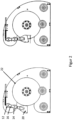
- Fig. 1 the basic principle of the ergometer brake according to the invention is shown.
- the basic components of the ergometer brake are a flywheel 22 and permanent magnets 20, which are arranged at a lower end of a lever 16.
- the upper end of the lever 16 is non-positively coupled to at least one spring 11.
- the flywheel 22 is set into a rotational movement via a pulling element 10 (e.g. rope, belt or chain).
- the tension element 10 is guided in an S-shape over deflection rollers 12, 14.
- the upper deflection roller 12 and the lower deflection roller 14 are arranged at the same distance from a central pivot point 13.
- the lower part of the lever 16 with the permanent magnets 20 is moved to the flywheel 22 when a user-specific pulling force is applied. The distance traveled and thus the magnetic field that forms depend on the tensile force applied.
- the two deflection rollers 12, 14 are located on the lever 16, which is connected to the spring 11 at the upper short end.
- the lower, longer part of the lever 16 includes the braking element (permanent magnets) for braking the connected flywheel.
- the braking element permanent magnets
- speed-dependent braking behavior is possible. Due to the resulting cable friction and bearing friction of the deflection rollers 12, 14 as well as the interaction of spring force and return force of the tension element 10, the lower part of the lever 16 described is guided in the direction of the flywheel 22 when the tension element 10 is pulled.
- the immersion depth of the lever 16 is determined by the pulling force of the exerciser. The closer the lever 16 is brought to the flywheel 22, the greater the magnetic field and thus the resulting braking force.
- the lever 16 is released from the flywheel 22 due to the acting spring force and enables the disk to run freely without resistance.
- FIG. 2 A rowing ergometer is shown, which is equipped with the ergometer brake according to the invention.
- the figure on the left shows the zero position, ie the position at which no tensile force is exerted on the tension element 10.
- the spring 11 expands and pivots the magnetic field formed by the permanent magnets 20 on the lever 16 into the flywheel 22 to different depths. This is done either radially or axially, depending on the application variant.
- the resistance decreases.
- the spring returns to its original state and thus withdraws the magnetic field from the flywheel 22. This allows the flywheel 22 to continue running unhindered, which corresponds, for example, to the gliding of a rowing boat.
- the lever 16 is immersed with a tensile force of 400 N about half of its width into the flywheel.
- 6 permanent magnets are used as excitation magnets (type S-15-08-N; magnetic flux density 0.535 T). The resistance behavior is therefore very similar to that of real rowing.
- An advantage of the system according to the invention is that no additional energy source is required to generate the braking force. Compared to air brakes, the system according to the invention is considerably quieter, so that the exerciser does not have to take any noise protection measures such as headphones, etc.
- FIG. 3 The force curve of a training device equipped with an ergometer brake according to the invention can be seen in comparison to a common rowing ergometer.
- the measurement delivers results that correspond to the required behavior.
- the strength value increases quickly, reaches an individual maximum and then drops to zero, as is typical for rowing.
- the data shows that the deficits of common rowing ergometers can be eliminated by achieving a dynamically changing effective resistance of the brake.
- the braking system according to the invention works quietly and requires no electricity and its resistance behavior is similar to the stroke of a rower.
- the ergometer brake according to the invention is therefore suitable for implementing a quiet, currentless, fluid dynamic resistance.
- the ergometer brake according to the invention enables the speed and the field of effect of the magnetic force on the flywheel to be increased as the tractive force increases, which triggers a higher braking torque.
Landscapes
- Health & Medical Sciences (AREA)
- General Health & Medical Sciences (AREA)
- Physical Education & Sports Medicine (AREA)
- Life Sciences & Earth Sciences (AREA)
- Biophysics (AREA)
- Orthopedic Medicine & Surgery (AREA)
- Physics & Mathematics (AREA)
- Electromagnetism (AREA)
- Cardiology (AREA)
- Vascular Medicine (AREA)
- Braking Arrangements (AREA)
Priority Applications (3)
| Application Number | Priority Date | Filing Date | Title |
|---|---|---|---|
| EP22166910.4A EP4257208B1 (fr) | 2022-04-06 | 2022-04-06 | Procédé et frein d'ergomètre destiné au changement dynamique dépendant de la force de la force de freinage d'un appareil d'entrainement |
| EP23719291.9A EP4504357A1 (fr) | 2022-04-06 | 2023-04-04 | Procédé et frein d'ergomètre pour une modification dynamique, dépendant de la force, de la force de freinage d'un appareil d'exercice |
| PCT/EP2023/025155 WO2023193953A1 (fr) | 2022-04-06 | 2023-04-04 | Procédé et frein d'ergomètre pour une modification dynamique, dépendant de la force, de la force de freinage d'un appareil d'exercice |
Applications Claiming Priority (1)
| Application Number | Priority Date | Filing Date | Title |
|---|---|---|---|
| EP22166910.4A EP4257208B1 (fr) | 2022-04-06 | 2022-04-06 | Procédé et frein d'ergomètre destiné au changement dynamique dépendant de la force de la force de freinage d'un appareil d'entrainement |
Publications (2)
| Publication Number | Publication Date |
|---|---|
| EP4257208A1 true EP4257208A1 (fr) | 2023-10-11 |
| EP4257208B1 EP4257208B1 (fr) | 2024-11-27 |
Family
ID=81327213
Family Applications (2)
| Application Number | Title | Priority Date | Filing Date |
|---|---|---|---|
| EP22166910.4A Active EP4257208B1 (fr) | 2022-04-06 | 2022-04-06 | Procédé et frein d'ergomètre destiné au changement dynamique dépendant de la force de la force de freinage d'un appareil d'entrainement |
| EP23719291.9A Withdrawn EP4504357A1 (fr) | 2022-04-06 | 2023-04-04 | Procédé et frein d'ergomètre pour une modification dynamique, dépendant de la force, de la force de freinage d'un appareil d'exercice |
Family Applications After (1)
| Application Number | Title | Priority Date | Filing Date |
|---|---|---|---|
| EP23719291.9A Withdrawn EP4504357A1 (fr) | 2022-04-06 | 2023-04-04 | Procédé et frein d'ergomètre pour une modification dynamique, dépendant de la force, de la force de freinage d'un appareil d'exercice |
Country Status (2)
| Country | Link |
|---|---|
| EP (2) | EP4257208B1 (fr) |
| WO (1) | WO2023193953A1 (fr) |
Families Citing this family (1)
| Publication number | Priority date | Publication date | Assignee | Title |
|---|---|---|---|---|
| DE102024113679A1 (de) * | 2024-05-15 | 2025-11-20 | Latupo GmbH | Vorrichtung zum Rudertraining mit einem Fluid-Schaufelrad |
Citations (8)
| Publication number | Priority date | Publication date | Assignee | Title |
|---|---|---|---|---|
| US3528653A (en) | 1967-10-13 | 1970-09-15 | Nissen Corp | Rowing machine and brake unit therefor |
| EP0176962A2 (fr) * | 1984-09-26 | 1986-04-09 | Tsunoda Jitensha Kabushiki Kaisha | Appareil d'exercice pour le pas |
| US4798378A (en) | 1985-07-15 | 1989-01-17 | Jones Robert S | Rowing machine |
| DE102008028377A1 (de) | 2008-06-13 | 2009-12-17 | Schaeffler Kg | Vorrichtung für ein Ergometer sowie Ergometer |
| WO2016009213A1 (fr) | 2014-07-17 | 2016-01-21 | Waterrower (Uk) Ltd | Machine d'exercice pourvue d'un recipient de fluide comportant des niveaux d'eau reglables |
| US20170036053A1 (en) * | 2015-08-07 | 2017-02-09 | Icon Health & Fitness, Inc. | Emergency Stop with Magnetic Brake for an Exercise Device |
| US20170106222A1 (en) * | 2015-10-16 | 2017-04-20 | Precor Incorporated | Variable distance eddy current braking system |
| CH712467A2 (de) | 2016-05-16 | 2017-11-30 | A Müller Peter | Rudersimulator. |
-
2022
- 2022-04-06 EP EP22166910.4A patent/EP4257208B1/fr active Active
-
2023
- 2023-04-04 EP EP23719291.9A patent/EP4504357A1/fr not_active Withdrawn
- 2023-04-04 WO PCT/EP2023/025155 patent/WO2023193953A1/fr not_active Ceased
Patent Citations (8)
| Publication number | Priority date | Publication date | Assignee | Title |
|---|---|---|---|---|
| US3528653A (en) | 1967-10-13 | 1970-09-15 | Nissen Corp | Rowing machine and brake unit therefor |
| EP0176962A2 (fr) * | 1984-09-26 | 1986-04-09 | Tsunoda Jitensha Kabushiki Kaisha | Appareil d'exercice pour le pas |
| US4798378A (en) | 1985-07-15 | 1989-01-17 | Jones Robert S | Rowing machine |
| DE102008028377A1 (de) | 2008-06-13 | 2009-12-17 | Schaeffler Kg | Vorrichtung für ein Ergometer sowie Ergometer |
| WO2016009213A1 (fr) | 2014-07-17 | 2016-01-21 | Waterrower (Uk) Ltd | Machine d'exercice pourvue d'un recipient de fluide comportant des niveaux d'eau reglables |
| US20170036053A1 (en) * | 2015-08-07 | 2017-02-09 | Icon Health & Fitness, Inc. | Emergency Stop with Magnetic Brake for an Exercise Device |
| US20170106222A1 (en) * | 2015-10-16 | 2017-04-20 | Precor Incorporated | Variable distance eddy current braking system |
| CH712467A2 (de) | 2016-05-16 | 2017-11-30 | A Müller Peter | Rudersimulator. |
Also Published As
| Publication number | Publication date |
|---|---|
| EP4257208B1 (fr) | 2024-11-27 |
| WO2023193953A1 (fr) | 2023-10-12 |
| EP4504357A1 (fr) | 2025-02-12 |
Similar Documents
| Publication | Publication Date | Title |
|---|---|---|
| DE102016118920B4 (de) | Trainingsgerät | |
| DE69207714T2 (de) | Programmierbare, trägheitssystem aufweisende trainingseinrichtung | |
| DE3878878T2 (de) | Fahrradtrainingsgeraet mit belastungseinrichtung. | |
| EP2351001B1 (fr) | Simulateur de mouvement et d'orientation | |
| EP3638382B1 (fr) | Appareil d'entraînement | |
| DE4126106A1 (de) | Widerstandsmechanismus | |
| DE102004031454A1 (de) | Pedalsimulator | |
| AT505617B1 (de) | Ergometrisches trainingsgerät | |
| EP4257208B1 (fr) | Procédé et frein d'ergomètre destiné au changement dynamique dépendant de la force de la force de freinage d'un appareil d'entrainement | |
| EP4366843B1 (fr) | Appareil d'entraînement destiné à la pratique d'un mouvement de poussée ou de traction | |
| EP4072933A1 (fr) | Dispositif d'actionnement, véhicule et procédé pour faire fonctionner un véhicule | |
| EP0081189A2 (fr) | Dispositif de freinage d'objets | |
| DE1648408A1 (de) | Vorrichtung und Verfahren zum Messen der Lastbetriebseigenschaften einer Antriebsmaschine | |
| DE102006031855A1 (de) | Brems-Vorrichtung für einspurige Fahrzeuge, vorzugsweise für Fahrräder oder Motorräder | |
| DE3205295A1 (de) | Vorrichtung zum abbremsen von gegenstaenden | |
| DE3939950A1 (de) | Stufenlos regelbare krafttrainingsmaschine | |
| DE648943C (de) | Drehzahlregler mit einer Wirbelstrombremse | |
| DE202006010633U1 (de) | Brems-System für Fahrzeuge aller Art | |
| DE202006010647U1 (de) | Brems-Vorrichtung für einspurige Fahrzeuge vorzugsweise für Fahrräder oder Motorräder | |
| DE4118082C1 (en) | Producing dynamic movement resistances in e - using brake with braking disc and control comprising force and RPM pick=ups, computer and braking force intensifier | |
| DE4419307A1 (de) | Hysteresebremse zur Bremskrafteinstellung bei ortsfesten Trainingsgeräten und Ergometern | |
| EP4201489A1 (fr) | Appareil d'entraînement et procédé de simulation d'un mouvement de gouvernail | |
| DE10247548A1 (de) | Ventilzeiteinstellungssteuerungs- bzw. Regelungsvorrichtung für einen Verbrennungsmotor | |
| DE102010050304A1 (de) | Trainingsgerät | |
| DE102020118016A1 (de) | Trainingsgerät und Verfahren zum Simulieren einer Ruderbewegung |
Legal Events
| Date | Code | Title | Description |
|---|---|---|---|
| PUAI | Public reference made under article 153(3) epc to a published international application that has entered the european phase |
Free format text: ORIGINAL CODE: 0009012 |
|
| STAA | Information on the status of an ep patent application or granted ep patent |
Free format text: STATUS: THE APPLICATION HAS BEEN PUBLISHED |
|
| AK | Designated contracting states |
Kind code of ref document: A1 Designated state(s): AL AT BE BG CH CY CZ DE DK EE ES FI FR GB GR HR HU IE IS IT LI LT LU LV MC MK MT NL NO PL PT RO RS SE SI SK SM TR |
|
| STAA | Information on the status of an ep patent application or granted ep patent |
Free format text: STATUS: REQUEST FOR EXAMINATION WAS MADE |
|
| 17P | Request for examination filed |
Effective date: 20240409 |
|
| RBV | Designated contracting states (corrected) |
Designated state(s): AL AT BE BG CH CY CZ DE DK EE ES FI FR GB GR HR HU IE IS IT LI LT LU LV MC MK MT NL NO PL PT RO RS SE SI SK SM TR |
|
| GRAP | Despatch of communication of intention to grant a patent |
Free format text: ORIGINAL CODE: EPIDOSNIGR1 |
|
| STAA | Information on the status of an ep patent application or granted ep patent |
Free format text: STATUS: GRANT OF PATENT IS INTENDED |
|
| INTG | Intention to grant announced |
Effective date: 20240620 |
|
| RAP1 | Party data changed (applicant data changed or rights of an application transferred) |
Owner name: MEDEVICE GMBH |
|
| GRAS | Grant fee paid |
Free format text: ORIGINAL CODE: EPIDOSNIGR3 |
|
| GRAA | (expected) grant |
Free format text: ORIGINAL CODE: 0009210 |
|
| STAA | Information on the status of an ep patent application or granted ep patent |
Free format text: STATUS: THE PATENT HAS BEEN GRANTED |
|
| RAP1 | Party data changed (applicant data changed or rights of an application transferred) |
Owner name: PHYSIOMED ELEKTROMEDIZIN AG |
|
| AK | Designated contracting states |
Kind code of ref document: B1 Designated state(s): AL AT BE BG CH CY CZ DE DK EE ES FI FR GB GR HR HU IE IS IT LI LT LU LV MC MK MT NL NO PL PT RO RS SE SI SK SM TR |
|
| REG | Reference to a national code |
Ref country code: GB Ref legal event code: FG4D Free format text: NOT ENGLISH |
|
| REG | Reference to a national code |
Ref country code: CH Ref legal event code: EP |
|
| REG | Reference to a national code |
Ref country code: DE Ref legal event code: R096 Ref document number: 502022002203 Country of ref document: DE |
|
| REG | Reference to a national code |
Ref country code: IE Ref legal event code: FG4D Free format text: LANGUAGE OF EP DOCUMENT: GERMAN |
|
| REG | Reference to a national code |
Ref country code: LT Ref legal event code: MG9D |
|
| REG | Reference to a national code |
Ref country code: NL Ref legal event code: MP Effective date: 20241127 |
|
| PG25 | Lapsed in a contracting state [announced via postgrant information from national office to epo] |
Ref country code: PT Free format text: LAPSE BECAUSE OF FAILURE TO SUBMIT A TRANSLATION OF THE DESCRIPTION OR TO PAY THE FEE WITHIN THE PRESCRIBED TIME-LIMIT Effective date: 20250327 Ref country code: HR Free format text: LAPSE BECAUSE OF FAILURE TO SUBMIT A TRANSLATION OF THE DESCRIPTION OR TO PAY THE FEE WITHIN THE PRESCRIBED TIME-LIMIT Effective date: 20241127 Ref country code: IS Free format text: LAPSE BECAUSE OF FAILURE TO SUBMIT A TRANSLATION OF THE DESCRIPTION OR TO PAY THE FEE WITHIN THE PRESCRIBED TIME-LIMIT Effective date: 20250327 |
|
| PG25 | Lapsed in a contracting state [announced via postgrant information from national office to epo] |
Ref country code: NL Free format text: LAPSE BECAUSE OF FAILURE TO SUBMIT A TRANSLATION OF THE DESCRIPTION OR TO PAY THE FEE WITHIN THE PRESCRIBED TIME-LIMIT Effective date: 20241127 Ref country code: FI Free format text: LAPSE BECAUSE OF FAILURE TO SUBMIT A TRANSLATION OF THE DESCRIPTION OR TO PAY THE FEE WITHIN THE PRESCRIBED TIME-LIMIT Effective date: 20241127 |
|
| PG25 | Lapsed in a contracting state [announced via postgrant information from national office to epo] |
Ref country code: BG Free format text: LAPSE BECAUSE OF FAILURE TO SUBMIT A TRANSLATION OF THE DESCRIPTION OR TO PAY THE FEE WITHIN THE PRESCRIBED TIME-LIMIT Effective date: 20241127 |
|
| PG25 | Lapsed in a contracting state [announced via postgrant information from national office to epo] |
Ref country code: ES Free format text: LAPSE BECAUSE OF FAILURE TO SUBMIT A TRANSLATION OF THE DESCRIPTION OR TO PAY THE FEE WITHIN THE PRESCRIBED TIME-LIMIT Effective date: 20241127 |
|
| PG25 | Lapsed in a contracting state [announced via postgrant information from national office to epo] |
Ref country code: NO Free format text: LAPSE BECAUSE OF FAILURE TO SUBMIT A TRANSLATION OF THE DESCRIPTION OR TO PAY THE FEE WITHIN THE PRESCRIBED TIME-LIMIT Effective date: 20250227 |
|
| PG25 | Lapsed in a contracting state [announced via postgrant information from national office to epo] |
Ref country code: GR Free format text: LAPSE BECAUSE OF FAILURE TO SUBMIT A TRANSLATION OF THE DESCRIPTION OR TO PAY THE FEE WITHIN THE PRESCRIBED TIME-LIMIT Effective date: 20250228 Ref country code: LV Free format text: LAPSE BECAUSE OF FAILURE TO SUBMIT A TRANSLATION OF THE DESCRIPTION OR TO PAY THE FEE WITHIN THE PRESCRIBED TIME-LIMIT Effective date: 20241127 |
|
| PG25 | Lapsed in a contracting state [announced via postgrant information from national office to epo] |
Ref country code: PL Free format text: LAPSE BECAUSE OF FAILURE TO SUBMIT A TRANSLATION OF THE DESCRIPTION OR TO PAY THE FEE WITHIN THE PRESCRIBED TIME-LIMIT Effective date: 20241127 |
|
| PG25 | Lapsed in a contracting state [announced via postgrant information from national office to epo] |
Ref country code: RS Free format text: LAPSE BECAUSE OF FAILURE TO SUBMIT A TRANSLATION OF THE DESCRIPTION OR TO PAY THE FEE WITHIN THE PRESCRIBED TIME-LIMIT Effective date: 20250227 |
|
| PG25 | Lapsed in a contracting state [announced via postgrant information from national office to epo] |
Ref country code: SM Free format text: LAPSE BECAUSE OF FAILURE TO SUBMIT A TRANSLATION OF THE DESCRIPTION OR TO PAY THE FEE WITHIN THE PRESCRIBED TIME-LIMIT Effective date: 20241127 |
|
| PG25 | Lapsed in a contracting state [announced via postgrant information from national office to epo] |
Ref country code: DK Free format text: LAPSE BECAUSE OF FAILURE TO SUBMIT A TRANSLATION OF THE DESCRIPTION OR TO PAY THE FEE WITHIN THE PRESCRIBED TIME-LIMIT Effective date: 20241127 |
|
| PG25 | Lapsed in a contracting state [announced via postgrant information from national office to epo] |
Ref country code: EE Free format text: LAPSE BECAUSE OF FAILURE TO SUBMIT A TRANSLATION OF THE DESCRIPTION OR TO PAY THE FEE WITHIN THE PRESCRIBED TIME-LIMIT Effective date: 20241127 |
|
| PG25 | Lapsed in a contracting state [announced via postgrant information from national office to epo] |
Ref country code: RO Free format text: LAPSE BECAUSE OF FAILURE TO SUBMIT A TRANSLATION OF THE DESCRIPTION OR TO PAY THE FEE WITHIN THE PRESCRIBED TIME-LIMIT Effective date: 20241127 |
|
| PGFP | Annual fee paid to national office [announced via postgrant information from national office to epo] |
Ref country code: AT Payment date: 20250721 Year of fee payment: 4 |
|
| PG25 | Lapsed in a contracting state [announced via postgrant information from national office to epo] |
Ref country code: SK Free format text: LAPSE BECAUSE OF FAILURE TO SUBMIT A TRANSLATION OF THE DESCRIPTION OR TO PAY THE FEE WITHIN THE PRESCRIBED TIME-LIMIT Effective date: 20241127 |
|
| PG25 | Lapsed in a contracting state [announced via postgrant information from national office to epo] |
Ref country code: CZ Free format text: LAPSE BECAUSE OF FAILURE TO SUBMIT A TRANSLATION OF THE DESCRIPTION OR TO PAY THE FEE WITHIN THE PRESCRIBED TIME-LIMIT Effective date: 20241127 |
|
| PG25 | Lapsed in a contracting state [announced via postgrant information from national office to epo] |
Ref country code: IT Free format text: LAPSE BECAUSE OF FAILURE TO SUBMIT A TRANSLATION OF THE DESCRIPTION OR TO PAY THE FEE WITHIN THE PRESCRIBED TIME-LIMIT Effective date: 20241127 |
|
| REG | Reference to a national code |
Ref country code: DE Ref legal event code: R097 Ref document number: 502022002203 Country of ref document: DE |
|
| PG25 | Lapsed in a contracting state [announced via postgrant information from national office to epo] |
Ref country code: SE Free format text: LAPSE BECAUSE OF FAILURE TO SUBMIT A TRANSLATION OF THE DESCRIPTION OR TO PAY THE FEE WITHIN THE PRESCRIBED TIME-LIMIT Effective date: 20241127 |
|
| PLBE | No opposition filed within time limit |
Free format text: ORIGINAL CODE: 0009261 |
|
| STAA | Information on the status of an ep patent application or granted ep patent |
Free format text: STATUS: NO OPPOSITION FILED WITHIN TIME LIMIT |
|
| REG | Reference to a national code |
Ref country code: CH Ref legal event code: L10 Free format text: ST27 STATUS EVENT CODE: U-0-0-L10-L00 (AS PROVIDED BY THE NATIONAL OFFICE) Effective date: 20251008 |
|
| 26N | No opposition filed |
Effective date: 20250828 |
|
| REG | Reference to a national code |
Ref country code: CH Ref legal event code: H13 Free format text: ST27 STATUS EVENT CODE: U-0-0-H10-H13 (AS PROVIDED BY THE NATIONAL OFFICE) Effective date: 20251125 |
|
| PG25 | Lapsed in a contracting state [announced via postgrant information from national office to epo] |
Ref country code: LU Free format text: LAPSE BECAUSE OF NON-PAYMENT OF DUE FEES Effective date: 20250406 |
|
| PG25 | Lapsed in a contracting state [announced via postgrant information from national office to epo] |
Ref country code: MC Free format text: LAPSE BECAUSE OF FAILURE TO SUBMIT A TRANSLATION OF THE DESCRIPTION OR TO PAY THE FEE WITHIN THE PRESCRIBED TIME-LIMIT Effective date: 20241127 |
|
| REG | Reference to a national code |
Ref country code: BE Ref legal event code: MM Effective date: 20250430 |
|
| PGFP | Annual fee paid to national office [announced via postgrant information from national office to epo] |
Ref country code: DE Payment date: 20251024 Year of fee payment: 4 |
|
| PG25 | Lapsed in a contracting state [announced via postgrant information from national office to epo] |
Ref country code: FR Free format text: LAPSE BECAUSE OF NON-PAYMENT OF DUE FEES Effective date: 20250430 |
|
| PG25 | Lapsed in a contracting state [announced via postgrant information from national office to epo] |
Ref country code: BE Free format text: LAPSE BECAUSE OF NON-PAYMENT OF DUE FEES Effective date: 20250430 |
|
| PG25 | Lapsed in a contracting state [announced via postgrant information from national office to epo] |
Ref country code: CH Free format text: LAPSE BECAUSE OF NON-PAYMENT OF DUE FEES Effective date: 20250430 |
|
| PG25 | Lapsed in a contracting state [announced via postgrant information from national office to epo] |
Ref country code: IE Free format text: LAPSE BECAUSE OF NON-PAYMENT OF DUE FEES Effective date: 20250406 |