EP4257253B1 - Module de nettoyage de récipients pour une machine de nettoyage de récipients modulaire et procédé de fonctionnement d'un module de nettoyage de récipients - Google Patents
Module de nettoyage de récipients pour une machine de nettoyage de récipients modulaire et procédé de fonctionnement d'un module de nettoyage de récipients Download PDFInfo
- Publication number
- EP4257253B1 EP4257253B1 EP23158982.1A EP23158982A EP4257253B1 EP 4257253 B1 EP4257253 B1 EP 4257253B1 EP 23158982 A EP23158982 A EP 23158982A EP 4257253 B1 EP4257253 B1 EP 4257253B1
- Authority
- EP
- European Patent Office
- Prior art keywords
- container cleaning
- liquid
- cleaning module
- rack
- nozzles
- Prior art date
- Legal status (The legal status is an assumption and is not a legal conclusion. Google has not performed a legal analysis and makes no representation as to the accuracy of the status listed.)
- Active
Links
Images

Classifications
-
- B—PERFORMING OPERATIONS; TRANSPORTING
- B08—CLEANING
- B08B—CLEANING IN GENERAL; PREVENTION OF FOULING IN GENERAL
- B08B3/00—Cleaning by methods involving the use or presence of liquid or steam
- B08B3/02—Cleaning by the force of jets or sprays
-
- B—PERFORMING OPERATIONS; TRANSPORTING
- B08—CLEANING
- B08B—CLEANING IN GENERAL; PREVENTION OF FOULING IN GENERAL
- B08B9/00—Cleaning hollow articles by methods or apparatus specially adapted thereto
- B08B9/08—Cleaning containers, e.g. tanks
- B08B9/20—Cleaning containers, e.g. tanks by using apparatus into or on to which containers, e.g. bottles, jars, cans are brought
- B08B9/28—Cleaning containers, e.g. tanks by using apparatus into or on to which containers, e.g. bottles, jars, cans are brought the apparatus cleaning by splash, spray, or jet application, with or without soaking
- B08B9/34—Arrangements of conduits or nozzles
-
- B—PERFORMING OPERATIONS; TRANSPORTING
- B08—CLEANING
- B08B—CLEANING IN GENERAL; PREVENTION OF FOULING IN GENERAL
- B08B13/00—Accessories or details of general applicability for machines or apparatus for cleaning
-
- B—PERFORMING OPERATIONS; TRANSPORTING
- B08—CLEANING
- B08B—CLEANING IN GENERAL; PREVENTION OF FOULING IN GENERAL
- B08B9/00—Cleaning hollow articles by methods or apparatus specially adapted thereto
- B08B9/08—Cleaning containers, e.g. tanks
- B08B9/20—Cleaning containers, e.g. tanks by using apparatus into or on to which containers, e.g. bottles, jars, cans are brought
- B08B9/28—Cleaning containers, e.g. tanks by using apparatus into or on to which containers, e.g. bottles, jars, cans are brought the apparatus cleaning by splash, spray, or jet application, with or without soaking
Definitions
- the invention relates to a container cleaning module for a modular container cleaning machine according to claim 1 and a method for operating a container cleaning module according to claim 14.
- WO 2018/107835 A1 discloses a dishwasher according to the preamble of claim 1, into which various inserts can be inserted, which can be equipped with different spray devices.
- US 5,566,695 discloses an apparatus and a method for cleaning containers by means of an automated and modular cleaning device.
- WO 2018/177575 A1 discloses a bottle treatment machine and a method for cleaning a pump/nozzle guard of the bottle treatment machine.
- the object of the invention is to provide a container cleaning module for a modular container cleaning machine and a method for operating the container cleaning module, which enables an economization of the cleaning process.
- the control device can be designed as a central or as several decentralized control devices.
- the at least one liquid outlet of the module housing can be opened and closed as required. Separated contaminants can be discharged through the liquid outlet. A separate outlet for discharging contaminants can be provided.
- the at least one liquid inlet of the module housing can be opened and closed as required.
- the same or different containers can be arranged in a rack. It can be provided that containers, for example PET containers or glass containers, which are less than a specified weight, can be fixed in the rack.
- a modular container cleaning machine with a container cleaning module enables adaptation of cleaning processes, for example according to containers provided in the rack, without time-consuming changes to the container cleaning module.
- a modular container cleaning machine can comprise several container cleaning modules, as described above or below. It can be provided that the several container cleaning modules comprise common liquid supply lines and liquid discharge lines. The several container cleaning modules can be operated independently of one another, for example in order to be able to carry out different cleaning processes in parallel (for example different liquid temperatures and/or duration of a cleaning process and/or dispensing the liquid by means of nozzles and/or flooding the interior of a container cleaning module).
- two or more container cleaning modules are provided adjacent to one another, so that a frame can be moved directly from one container cleaning module into the adjacent container cleaning module.
- a first end of each mandrel can comprise one or more nozzles.
- an internal cleaning of the container can be carried out by dispensing liquid towards a bottom of the container.
- several nozzles can be provided along each mandrel By providing several nozzles, the internal cleaning of a container can be improved. For example, 40 to 60 mandrels can be provided per rack.
- a first/the first end of each mandrel can have a maximum first diameter, which can correspond to an opening diameter of an opening with which a container can be applied to one of the mandrels, and a second end of the mandrel can have a second diameter, which can be 2% to 5% smaller than the first diameter.
- This second diameter can create a gap between the mandrel and the opening of the container when a container is applied to the mandrel. This allows the liquid that was applied and sprayed using the nozzle or nozzles of the mandrel to flow away. Any contaminants that were released by the internal spraying can also flow away and leave the container.
- Each mandrel may comprise an inverted circular frustum.
- a first end of the inverted circular frustum may be convex. For example, liquid may drain from the first end of the mandrel.
- the at least one liquid supply line can be designed to guide liquid to the nozzle(s) of the mandrels.
- the liquid can comprise lye and/or acid and/or water.
- Each frame of the at least one frame can comprise additional nozzles for external spraying of containers.
- the additional nozzles can also be supplied with liquid by means of the at least one liquid supply line.
- Each rack of the at least one rack may comprise rack piping.
- the rack piping may comprise a pipe connecting the at least one liquid supply line, the nozzle or nozzles of the mandrels and optionally the additional nozzles for a liquid supply.
- the liquid supply line can be designed to be connectable to the frame piping.
- the liquid supply line of the frame can be designed to be connectable to the liquid inlet of the module housing.
- Each frame of the at least one frame can comprise a plurality of compartments for receiving one or more containers.
- at least one of the plurality of mandrels can be arranged in each compartment.
- one or more locking pins can be assigned to each of the compartments.
- compartments can be arranged on a frame as described above or below, for example by means of a positive or non-positive connection or for example by means of clip elements and/or clip connections.
- a combination of compartments and frame can be regarded as two-part. It can also be provided that the compartments are provided in one piece with a frame as described above or below.
- the compartments may comprise horizontal and vertical struts.
- the struts may be designed such that one or more upside down containers, which may be arranged in a compartment, are supported by the struts.
- the compartments can be designed and arranged relative to the frame or to the spikes of a frame in such a way that a spike can be arranged in a compartment.
- a spike can be arranged in a compartment.
- the frame and the spikes, the dimensions of the containers to be cleaned, the dimensions of the module housing and the like can be taken into account.
- Each frame of the at least one frame can have a length in a range of 1 meter to 2 meters and a width in a range of 1 meter to 1.5 meters, wherein, for example, a base area of the at least one frame can be rectangular or square.
- the module housing can have a length and a width each in a range of 2 meters to 5 meters and a height can be in a range between 0.4 meters and 4 meters, whereby, for example, a base area of the module housing can be rectangular or square.
- the dimensions of the frame(s) and module housing and insertion device can be designed to match each other for a container cleaning module.
- two or more of the at least one insertion device are present, these can be arranged next to one another and/or one above the other in the module housing. Accordingly, two or more frames can then be arranged next to one another and/or one above the other in the module housing.
- the module housing can have nozzles on the inside. These nozzles can be used for external cleaning of the containers and/or for internal cleaning of the module housing. Cleaning of a frame arranged in the module housing is also possible.
- the nozzles can be provided on side walls, on the floor and/or on a cover of the module housing.
- the nozzles arranged in the cover can also be used to ventilate the module housing during flooding.
- the module housing can comprise ring-shaped nozzles which, in an operating arrangement of the at least one frame in the Module housings can be arranged such that the annular nozzles can be arranged flush above the mandrels.
- the operating arrangement here is to be understood as meaning that one or more racks have been introduced into the module housing and at least one openable and liquid-tight closable access has been closed.
- the liquid outlet can comprise a movable squeegee and/or a movable grid.
- the squeegee and/or the grid labels or label residues in the liquid that is to be discharged through the liquid outlet can be shredded.
- the movable squeegee and/or the movable grid can be designed to be movable towards and away from a discharge channel enclosed by the liquid outlet. In this way, labels or label residues can be prevented from getting stuck.
- a cleaning nozzle for the movable squeegee and/or the movable grid can be provided in the area of the discharge channel. In this way, adhering labels or label residues can be removed from the squeegee and/or the grid.
- a multi-way valve can be provided after the movable squeegee and/or the movable grid.
- liquid discharged from the liquid outlet can be fed to different lines, for example for reusing the liquid, such as preheating liquid that can be fed to a container cleaning module.
- a removal device for example a drawer, can be arranged in the area of the discharge channel for manual or automatic removal of separated contaminants.
- the at least one openable and liquid-tightly closable access can be designed to be liquid-tightly lockable by means of at least one fitting and pin in at least two different positions.
- the fitting can be arranged on a frame of the module housing and the pins on a door of the module housing, or vice versa. Since at least two different positions are provided for locking, a liquid-tightly closable access can be obtained. For example, after closing the access, the interior of the module housing can be flooded with liquid without liquid escaping from the module housing.
- the module housing can comprise two accesses that can be opened and sealed in a liquid-tight manner.
- the two accesses that can be opened and sealed in a liquid-tight manner can be arranged on opposite sides of the module housing.
- the two accesses can enable a frame to be inserted through a first of the two accesses and the frame to be removed through a second of the two accesses.
- a frame can be moved from a first module housing of a first container cleaning module to a second module housing of a second container cleaning module, for example, to carry out a further cleaning process there or to carry out rinsing with water.
- the sensor system includes detection and execution sensors.
- the detection sensors detect temperatures of the liquid in the container cleaning module and/or the degree of contamination of the liquid discharged through the liquid outlet and the like.
- the execution sensor initiates execution processes based on values received, determined and/or entered before a cleaning process and/or values received, determined and/or entered during a cleaning process. To do this, the execution sensor uses values recorded by the detection sensor that it receives from the detection sensor.
- control device can be designed to be programmable in memory.
- the container cleaning module can further comprise at least one drip tray for arrangement under the at least one frame.
- the drip tray can be placed outside the module housing. After a cleaning process, a frame with cleaned containers can be arranged flush above the drip tray. In this way, any liquid residues from the containers, the frame, the spikes and/or the compartments can drip into the drip tray. It can also be provided that a frame with containers to be cleaned - i.e. before a cleaning process - can be arranged flush above the drip tray. In this way, for example, product residues (liquid and dried) that adhere to and/or to the containers to be cleaned can be caught in the drip tray.
- the drip tray can have a base area that can be the same size as, or larger or smaller than, a base area of the frame.
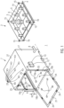
- the Figure 1 shows a frame 2 and a module housing 7 of a container cleaning module 1 for a modular container cleaning machine.
- the illustration shows a frame 2 for receiving upside down containers 3; the container cleaning module 1 can comprise more than one frame 2.
- the frame 2 comprises a liquid supply line 4 and several mandrels 5 onto which the upside down containers 3 can be placed.
- the mandrels 5 have a nozzle 6 at a first end for cleaning the inside of the containers 3 placed thereon and oriented upside down.
- the frame 2 comprises a frame piping 14 which connects the mandrels 5 to pipes of the frame piping 14 for a liquid supply, wherein the liquid supply line 4 is designed to be connectable to the frame piping 14.
- the liquid supply line 4 can therefore be used to supply the mandrels 5 with the liquid required so that they can be used for cleaning the inside of a container 3 placed thereon and oriented upside down.
- Additional nozzles 15 are provided on the frame 2 for external spraying of containers 3, which are arranged upside down on the mandrels 5.
- the additional nozzles 15 can be connected to the frame piping 14, so that a liquid supply with pipes of the frame piping 14 is possible through the liquid supply line 4.
- the frame 2 has Figure 1 on two opposite sides slide rails 16.
- the slide rails 16 can be positioned on or in a corresponding insertion device 10a, 10b of the module housing 7 and can be moved along this.
- the frame 2 can comprise rollers which can be positioned on or in a corresponding insertion device 10a, 10b of the module housing 7 and can be moved along this.
- the module housing 7 has two insertion devices 10a, 10b on the inside of two side walls 17 arranged opposite one another.
- the first insertion device 10a is arranged at a first height h1 and the second insertion device 10b at a second height h2.
- the first and second heights h1, h2 are provided in such a way that a frame 2 can be inserted in each case, for example without coming into contact with the other frame 2.
- Dimensions of the frame 2 can be taken into account for this purpose. For example, in addition to a height of the frame 2, an additional amount can be taken into account that takes into account containers 3 present on the frame 2, for example their length.
- the module housing 7 comprises a liquid inlet 8 by means of which nozzles 18, 19, 20, 23 in the interior of the module housing 7 can be supplied with liquid.
- the liquid supply line 4 of the frame 2 can also be connected to the liquid inlet 8 by means of a pipe supply present in the module housing 7.
- First nozzles 18 are arranged on a door 21 of the module housing 7 in the interior.
- Second nozzles 19 are arranged on the floor 22 of the module housing 7 in the interior.
- Third nozzles 20 are arranged on the side walls 17 of the module housing 7 in the interior.
- ring-shaped nozzles 23 are provided on the cover 27 of the module housing 7 in the interior, which are arranged in an operating arrangement of the frame 2 in the module housing 7 in such a way that the ring-shaped nozzles 23 are arranged in alignment above the mandrels 5.
- the module housing 7 comprises a liquid outlet 9 through which liquid discharged inside the module housing 7 can be discharged, for example together with labels detached from containers, label residues and/or dried beverage residues or the like.
- the module housing 7 further comprises an openable and liquid-tight closable access 11 for introducing or removing one or more racks 2 into or from the interior of the module housing 7.
- the access 11 can be closed by means of the door 21.
- the door hinge is arranged horizontally on a lower edge of the frame 26 of the module housing 7.
- fittings 24 are provided on the door 21 at four different positions, into which pins 25 engage after the door 21 is closed, which are arranged on the frame 26 of the module housing 7 at the positions that correspond to those of the fittings 24 of the door 21.
- the container cleaning module 1 also comprises a control device 12 and a sensor system 13 for controlling and monitoring a cleaning process by the container cleaning module 1.
- the control device 12 and the sensor system 13 are arranged on the outside of the module housing 7, whereby electrical and sensor connections can be provided inside the module housing 7.
- the control device 12 and the sensor system 13 can also be provided in other positions of the container cleaning module 1.
- the Figure 2A shows a first embodiment of a mandrel 28, which is connected to a partially shown frame piping 30 of a frame, as described above or further below.
- the illustration shows a schematic longitudinal section.
- the mandrel 28 can be one-piece with the frame piping 30 or the mandrel 28 can be applied to the frame piping 30 in a force-fitting or form-fitting manner.
- a fluid connection is provided between the mandrel 28 and the frame piping 30.
- a first end 31 of the mandrel 28 has a first diameter d1, wherein the first diameter d1 corresponds at most to an opening diameter of an opening through which a container is to be able to be applied to the mandrel 28.
- the first end 31 of the mandrel 28 comprises a nozzle 29, by means of which liquid can be applied and sprayed for internal spraying of a container applied to the mandrel 28.
- a second end 32 of the mandrel 28 has a second diameter d2 which is 2% to 5% smaller than the first diameter d1.
- This second diameter d2 creates a gap between the mandrel 28 and the opening of the container when a container is placed on the mandrel 28. This allows the liquid which has been dispensed and sprayed by means of the nozzle 29 to flow away, taking with it any possible impurities which have been released by the internal spraying.
- the mandrel 28 is designed as an inverted circular truncated cone, wherein the inverted circular truncated cone has a length I which can, for example, be smaller than a height of a container applied to the mandrel 28.
- the Figure 2B shows a second embodiment of a mandrel 33, which is connected to a partially shown frame piping 30 of a frame, as described above or further below.
- the illustration shows a schematic longitudinal section.
- the mandrel 33 essentially corresponds to the mandrel 28 of the first embodiment in shape and properties, whereby the mandrel 33 of the second embodiment not only has a nozzle 35 at the first end 34, but also nozzles 36 on the lateral surfaces of the inverted circular truncated cone. Two of these nozzles 36 can be seen in the illustration. By means of these two nozzles 36, liquid, which is supplied by means of the frame piping 30, can be dispensed and sprayed for internal spraying of a container placed on the mandrel 33.
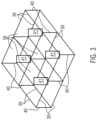
- the Figure 3 shows compartments 38 for accommodating one or more containers.
- the compartments 38 can be arranged on a frame as described above or below, for example by means of a positive or non-positive connection or for example by means of clip elements and/or clip connections; the combination of compartments 38 and frame can be regarded as two-part. It can also be provided that the compartments 38 are provided in one piece with a frame as described above or below.
- compartments 38 which comprise horizontal struts 39 and vertical struts 40.
- the struts 39, 40 are designed such that one or more upside down containers arranged in a compartment 38 are supported by the struts 39, 40.
- the struts 39, 40 can be designed such that the compartments 38 are stable.
- the compartments 38 are designed and can be arranged relative to the frame or to the mandrels 41 of a frame in such a way that a mandrel 41 is arranged in a compartment 38.
- the frame and the mandrels dimensions of containers to be cleaned, dimensions of the module housing and the like can be taken into account.
Landscapes
- Engineering & Computer Science (AREA)
- Mechanical Engineering (AREA)
- Cleaning In General (AREA)
- Cleaning By Liquid Or Steam (AREA)
Claims (14)
- Module de nettoyage de récipients (1) pour une machine de nettoyage de récipients modulaire, le module de nettoyage de récipients (1) comprenant :- au moins un châssis (2) pour recevoir des récipients (3) orientés à l'envers, chaque au moins un châssis (2) comprenant au moins une conduite d'alimentation de liquide (4) et chaque au moins un châssis (2) comprenant plusieurs broches (5, 28, 33) sur lesquelles les récipients (3) orientés à l'envers peuvent être appliqués, chacune des plusieurs broches (5, 28, 33) comprenant au moins une buse (6, 29, 35, 36) pour un nettoyage intérieur d'un récipient (3) orienté à l'envers qui y est appliqué,- un boîtier de module (7) avec :- au moins une entrée de liquide (8),- au moins une sortie de liquide (9),- au moins un dispositif d'insertion (10a, 10b) pour recevoir un ou plusieurs du au moins un châssis (2),- au moins un accès (11) pouvant être ouvert et fermé de manière étanche aux liquides pour introduire ou déployer le au moins un châssis (2) à l'intérieur ou à l'extérieur du boîtier de module (7),- un dispositif de commande (12) et un système de capteurs (13) pour une commande et une surveillance d'un processus de nettoyage par l'intermédiaire du module de nettoyage de récipients (1), caractérisé en ce que le système de capteurs (13) comprend un système de capteurs de détection et d'exécution, le système de capteurs de détection étant conçu pour détecter la température du liquide dans le module de nettoyage de récipients et/ou le degré de salissure du liquide évacué par la sortie de liquide (9), le système de capteurs d'exécution étant conçu pour initier des processus d'exécution sur la base de valeurs déterminées avant un processus de nettoyage et/ou pendant un processus de nettoyage, le système de capteurs d'exécution utilisant pour cela des valeurs détectées par le système de capteurs de détection, que le système de capteurs d'exécution a reçues du système de capteurs de détection.
- Module de nettoyage de récipients selon la revendication 1, dans lequel une première extrémité (31, 34) de chaque broche (5, 28, 33) comprend une ou plusieurs buses (6, 29, 35), par exemple plusieurs buses (35, 36) étant prévues le long de chaque broche (33), par exemple 40 à 60 broches (5, 28, 33) étant prévues par châssis.
- Module de nettoyage de récipients selon la revendication 1 ou 2, dans lequel chaque broche (28, 33) comprend un tronc de cône circulaire inversé.
- Module de nettoyage de récipients selon l'une quelconque des revendications 1 à 3, dans lequel chaque au moins une conduite d'alimentation de liquide (4) est conçue pour diriger du liquide vers la ou les buses (6, 29, 35, 36) des broches (5, 28, 33).
- Module de nettoyage de récipients selon l'une quelconque des revendications 1 à 4, dans lequel chaque châssis (2) du au moins un châssis (2) :- comprend des buses supplémentaires (15) pour une pulvérisation externe de récipients (3) et/ou- comprend une tuyauterie de support (14), dans lequel, par exemple, la conduite d'alimentation de liquide (4) est formée pouvant être reliée à la tuyauterie de châssis (14) et/ou- comprend plusieurs compartiments (38) pour recevoir un ou plusieurs récipients (3), au moins une des plusieurs broches (5) étant par exemple agencée dans chaque compartiment (38), une ou plusieurs broches de verrouillage étant par exemple affectées à chacun des compartiments (38), et/ou- présente une longueur dans une plage de 1 mètre à 1,5 mètre et une largeur dans une plage de 1 mètre à 1,5 mètre, une surface de base du au moins un châssis (2) étant par exemple rectangulaire ou carrée.
- Module de nettoyage de récipients selon l'une quelconque des revendications 1 à 5, dans lequel le boîtier de module (7) présente une longueur et une largeur respectivement dans une plage de 2 mètres à 5 mètres, et dans lequel une hauteur est dans une plage comprise entre 0,4 mètre et 2 mètres, dans lequel, par exemple, une surface de base du boîtier de module (7) est rectangulaire ou carrée.
- Module de nettoyage de récipients selon l'une quelconque des revendications 1 à 6, dans lequel, en présence de deux ou plus desdits au moins un dispositif d'insertion (10), ceux-ci sont agencés l'un à côté de l'autre et/ou l'un au-dessus de l'autre dans le boîtier de module (7).
- Module de nettoyage de récipients selon l'une quelconque des revendications 1 à 7, dans lequel le boîtier de module (7) présente des buses (18, 19, 20, 23) en son sein, dans lequel, par exemple, les buses (20) sont prévues sur les parois latérales (17), les buses (19) sont prévues sur le fond (22) et/ou les buses (23) sont prévues sur un couvercle (27) du boîtier de module (7), dans lequel, par exemple, le boîtier de module (7) comprend des buses annulaires (23) qui sont agencées dans un agencement de fonctionnement du au moins un châssis dans le boîtier de module (7), de sorte que les buses annulaires (23) sont agencées en affleurement au-dessus des mandrins (5).
- Module de nettoyage de récipients selon l'une quelconque des revendications 1 à 8, dans lequel la sortie de liquide (9) comprend une raclette mobile et/ou une grille mobile, dans lequel, par exemple, la raclette mobile et/ou la grille mobile peuvent être déplacées vers et éloignées d'un canal de décharge comprenant la sortie de liquide (9), dans lequel, par exemple, une buse de nettoyage pour la raclette mobile et/ou la grille mobile est prévue dans la zone du canal de décharge, dans lequel, par exemple, après la raclette mobile et/ou la grille mobile, une vanne à plusieurs voies est prévue.
- Module de nettoyage de récipients selon l'une quelconque des revendications 1 à 9, dans lequel le au moins un accès (11) pouvant être ouvert et pouvant être fermé de manière étanche aux liquides peut être verrouillé de manière étanche aux liquides dans au moins deux positions différentes au moyen d'au moins une butée (24) et d'un tenon (25).
- Module de nettoyage de récipients selon l'une quelconque des revendications 1 à 10, dans lequel le boîtier de module (7) comprend deux accès pouvant être ouverts et pouvant être fermés de manière étanche aux liquides, dans lequel, par exemple, les deux accès pouvant être ouverts et pouvant être fermés de manière étanche aux liquides sont agencés sur des côtés opposés du boîtier de module (7).
- Module de nettoyage de récipients selon l'une des revendications 1 à 11, dans lequel le dispositif de commande (12) est conçu pour être à mémoire programmable.
- Module de nettoyage de récipients selon l'une quelconque des revendications 1 à 12, comprenant en outre au moins un bac d'égouttement à placer sous ledit au moins un châssis.
- Procédé pour faire fonctionner un module de nettoyage de récipients (1) pour une machine modulaire de nettoyage de récipients selon l'une des revendications 1 à 13.
Applications Claiming Priority (1)
| Application Number | Priority Date | Filing Date | Title |
|---|---|---|---|
| DE102022108607.0A DE102022108607A1 (de) | 2022-04-08 | 2022-04-08 | Behälterreinigungsmodul für eine modulare Behälterreinigungsmaschine und Verfahren zum Betreiben eines Behälterreinigungsmoduls |
Publications (3)
| Publication Number | Publication Date |
|---|---|
| EP4257253A1 EP4257253A1 (fr) | 2023-10-11 |
| EP4257253B1 true EP4257253B1 (fr) | 2024-12-04 |
| EP4257253C0 EP4257253C0 (fr) | 2024-12-04 |
Family
ID=85384461
Family Applications (1)
| Application Number | Title | Priority Date | Filing Date |
|---|---|---|---|
| EP23158982.1A Active EP4257253B1 (fr) | 2022-04-08 | 2023-02-28 | Module de nettoyage de récipients pour une machine de nettoyage de récipients modulaire et procédé de fonctionnement d'un module de nettoyage de récipients |
Country Status (4)
| Country | Link |
|---|---|
| EP (1) | EP4257253B1 (fr) |
| CN (1) | CN116889995A (fr) |
| BR (1) | BR102023006394A2 (fr) |
| DE (1) | DE102022108607A1 (fr) |
Family Cites Families (14)
| Publication number | Priority date | Publication date | Assignee | Title |
|---|---|---|---|---|
| GB1380788A (en) * | 1971-07-19 | 1975-01-15 | Rapp H | Container-washing machine |
| DE2919140A1 (de) | 1979-05-11 | 1980-11-27 | Helmut Rapp | Spuelmaschine |
| US5409545A (en) * | 1993-03-04 | 1995-04-25 | Environmental Sampling Supply, Inc. | Apparatus and method for cleaning containers |
| JP3679854B2 (ja) * | 1996-04-10 | 2005-08-03 | 三菱重工業株式会社 | 容器洗浄ノズル及び容器洗浄・殺菌方法 |
| CN204074660U (zh) * | 2014-09-26 | 2015-01-07 | 内蒙古蒙牛乳业(集团)股份有限公司 | 器皿的清洗仪 |
| FR3055228B1 (fr) * | 2016-08-23 | 2019-06-14 | Stephane Meyrieux | Appareil de nettoyage par pulverisation d'un liquide, de bouteilles a goulot de differentes grandes capacites |
| CN206104491U (zh) * | 2016-08-31 | 2017-04-19 | 华北制药金坦生物技术股份有限公司 | 小口径血清瓶用清洗装置 |
| US10517458B2 (en) * | 2016-12-16 | 2019-12-31 | Midea Group Co., Ltd. | Dishwasher including silverware basket with integrated interior sprayer |
| DE102017205551A1 (de) * | 2017-03-31 | 2018-10-04 | Krones Ag | Flaschenbehandlungsmaschine und Verfahren zum Reinigen des Pumpen-/Düsenschutzes der Flaschenbehandlungsmaschine |
| CN208261482U (zh) * | 2018-02-28 | 2018-12-21 | 天津瑞鹏医疗器械有限公司 | 一种透析液储液桶清洗装置 |
| CN208743142U (zh) | 2018-04-24 | 2019-04-16 | 复旦大学附属中山医院 | 一种模块化清洗消毒架 |
| CN211464048U (zh) * | 2019-10-24 | 2020-09-11 | 彭安志 | 一种冶金用清洗装置上的排污结构 |
| CN214638915U (zh) * | 2021-03-26 | 2021-11-09 | 黄河科技学院 | 一种生物制药用实验瓶清洗装置 |
| CN215258013U (zh) * | 2021-07-01 | 2021-12-21 | 费县大陆阀门有限公司 | 一种带过滤装置的防倒流止回阀 |
-
2022
- 2022-04-08 DE DE102022108607.0A patent/DE102022108607A1/de active Pending
-
2023
- 2023-02-28 EP EP23158982.1A patent/EP4257253B1/fr active Active
- 2023-04-05 BR BR102023006394-2A patent/BR102023006394A2/pt not_active Application Discontinuation
- 2023-04-07 CN CN202310363226.7A patent/CN116889995A/zh active Pending
Also Published As
| Publication number | Publication date |
|---|---|
| BR102023006394A2 (pt) | 2023-10-24 |
| CN116889995A (zh) | 2023-10-17 |
| DE102022108607A1 (de) | 2023-10-12 |
| EP4257253A1 (fr) | 2023-10-11 |
| EP4257253C0 (fr) | 2024-12-04 |
Similar Documents
| Publication | Publication Date | Title |
|---|---|---|
| DE68905970T2 (de) | Chemikalien-Ausgabegerät. | |
| DE19741242C1 (de) | Anlage zum Reinigen einer Abfüllanlage | |
| EP4175770A1 (fr) | Station de traitement, unité de traitement et procédé de traitement de pièces | |
| EP4175766B1 (fr) | Station de traitement, installation de traitement et procédé de traitement de pièces | |
| EP1403187A1 (fr) | Machine d'emballage avec dispositif de nettoyage | |
| EP3248699B1 (fr) | Dispositif de nettoyage de pompes de reservoirs avec une lance de pompe pour des milieu fluide | |
| DE102011085581A1 (de) | Transportsystem für Behälterverschlüsse | |
| DE3339930A1 (de) | Verfahren und vorrichtung zum sterilisieren von zur aufnahme von molkereiprodukten bestimmter becherfoermiger behaelter | |
| EP3519114B1 (fr) | Dispositif de nettoyage de bouteilles et procédé pour le nettoyage de bouteilles utilisant le dispositif de nettoyage de bouteilles | |
| EP4257253B1 (fr) | Module de nettoyage de récipients pour une machine de nettoyage de récipients modulaire et procédé de fonctionnement d'un module de nettoyage de récipients | |
| DE102021122448A1 (de) | Reinigungsmodul zur stationären Außenreinigung von KEGs | |
| EP2584298A2 (fr) | Dispositif de séchage pour récipient et procédé de nettoyage d'un tel dispositif de séchage | |
| EP3310400B1 (fr) | Dispositif de traitement de stérilisation | |
| EP4194112B1 (fr) | Dispositif de pulvérisation et procédé de pulvérisation interne de récipients | |
| EP4175765B1 (fr) | Station de traitement, installation de traitement et procédé de traitement de pièces | |
| DE102019135604A1 (de) | Kippvorrichtung für behälter für flüssigkeiten zur behandlung derselben und dazugehöriges behandlungsverfahren | |
| EP2072154A2 (fr) | Procédé et dispositif de nettoyage de pièces à usiner | |
| EP4257252A1 (fr) | Machine de nettoyage de récipients modulaire et procédé de fonctionnement d'une machine de nettoyage de récipients modulaire | |
| DE102023123691A1 (de) | Abscheidungsstation sowie Vorrichtung zur Erzeugung von Kontaktmetallisierungen | |
| EP2839846B1 (fr) | Dispositif de traitement de récipients dans une installation de remplissage de boissons | |
| AT519426B1 (de) | Behälter mit Vorrichtung zur Innenreinigung | |
| EP3927225B1 (fr) | Système de panier de lavage pour nettoyer un article à nettoyer présentant au moins un espace creux | |
| DE19707712C1 (de) | Verfahren und Kühlmitteltank zum Kalibrieren und Kühlen eines extrudierten Kunststoffprofils | |
| DE4434407A1 (de) | Anlage zum Reinigen und Befüllen einer Folge von Getränkebehältern | |
| EP0447954A2 (fr) | Poste d'injection |
Legal Events
| Date | Code | Title | Description |
|---|---|---|---|
| PUAI | Public reference made under article 153(3) epc to a published international application that has entered the european phase |
Free format text: ORIGINAL CODE: 0009012 |
|
| STAA | Information on the status of an ep patent application or granted ep patent |
Free format text: STATUS: THE APPLICATION HAS BEEN PUBLISHED |
|
| AK | Designated contracting states |
Kind code of ref document: A1 Designated state(s): AL AT BE BG CH CY CZ DE DK EE ES FI FR GB GR HR HU IE IS IT LI LT LU LV MC ME MK MT NL NO PL PT RO RS SE SI SK SM TR |
|
| STAA | Information on the status of an ep patent application or granted ep patent |
Free format text: STATUS: REQUEST FOR EXAMINATION WAS MADE |
|
| 17P | Request for examination filed |
Effective date: 20240205 |
|
| RBV | Designated contracting states (corrected) |
Designated state(s): AL AT BE BG CH CY CZ DE DK EE ES FI FR GB GR HR HU IE IS IT LI LT LU LV MC ME MK MT NL NO PL PT RO RS SE SI SK SM TR |
|
| GRAP | Despatch of communication of intention to grant a patent |
Free format text: ORIGINAL CODE: EPIDOSNIGR1 |
|
| STAA | Information on the status of an ep patent application or granted ep patent |
Free format text: STATUS: GRANT OF PATENT IS INTENDED |
|
| INTG | Intention to grant announced |
Effective date: 20240828 |
|
| GRAS | Grant fee paid |
Free format text: ORIGINAL CODE: EPIDOSNIGR3 |
|
| GRAA | (expected) grant |
Free format text: ORIGINAL CODE: 0009210 |
|
| STAA | Information on the status of an ep patent application or granted ep patent |
Free format text: STATUS: THE PATENT HAS BEEN GRANTED |
|
| AK | Designated contracting states |
Kind code of ref document: B1 Designated state(s): AL AT BE BG CH CY CZ DE DK EE ES FI FR GB GR HR HU IE IS IT LI LT LU LV MC ME MK MT NL NO PL PT RO RS SE SI SK SM TR |
|
| REG | Reference to a national code |
Ref country code: CH Ref legal event code: EP |
|
| REG | Reference to a national code |
Ref country code: DE Ref legal event code: R096 Ref document number: 502023000353 Country of ref document: DE |
|
| REG | Reference to a national code |
Ref country code: IE Ref legal event code: FG4D Free format text: LANGUAGE OF EP DOCUMENT: GERMAN |
|
| U01 | Request for unitary effect filed |
Effective date: 20241223 |
|
| U07 | Unitary effect registered |
Designated state(s): AT BE BG DE DK EE FI FR IT LT LU LV MT NL PT RO SE SI Effective date: 20250114 |
|
| U20 | Renewal fee for the european patent with unitary effect paid |
Year of fee payment: 3 Effective date: 20250115 |
|
| PG25 | Lapsed in a contracting state [announced via postgrant information from national office to epo] |
Ref country code: HR Free format text: LAPSE BECAUSE OF FAILURE TO SUBMIT A TRANSLATION OF THE DESCRIPTION OR TO PAY THE FEE WITHIN THE PRESCRIBED TIME-LIMIT Effective date: 20241204 |
|
| PG25 | Lapsed in a contracting state [announced via postgrant information from national office to epo] |
Ref country code: ES Free format text: LAPSE BECAUSE OF FAILURE TO SUBMIT A TRANSLATION OF THE DESCRIPTION OR TO PAY THE FEE WITHIN THE PRESCRIBED TIME-LIMIT Effective date: 20241204 |
|
| PG25 | Lapsed in a contracting state [announced via postgrant information from national office to epo] |
Ref country code: NO Free format text: LAPSE BECAUSE OF FAILURE TO SUBMIT A TRANSLATION OF THE DESCRIPTION OR TO PAY THE FEE WITHIN THE PRESCRIBED TIME-LIMIT Effective date: 20250304 |
|
| PG25 | Lapsed in a contracting state [announced via postgrant information from national office to epo] |
Ref country code: GR Free format text: LAPSE BECAUSE OF FAILURE TO SUBMIT A TRANSLATION OF THE DESCRIPTION OR TO PAY THE FEE WITHIN THE PRESCRIBED TIME-LIMIT Effective date: 20250305 |
|
| PG25 | Lapsed in a contracting state [announced via postgrant information from national office to epo] |
Ref country code: RS Free format text: LAPSE BECAUSE OF FAILURE TO SUBMIT A TRANSLATION OF THE DESCRIPTION OR TO PAY THE FEE WITHIN THE PRESCRIBED TIME-LIMIT Effective date: 20250304 |
|
| PG25 | Lapsed in a contracting state [announced via postgrant information from national office to epo] |
Ref country code: SM Free format text: LAPSE BECAUSE OF FAILURE TO SUBMIT A TRANSLATION OF THE DESCRIPTION OR TO PAY THE FEE WITHIN THE PRESCRIBED TIME-LIMIT Effective date: 20241204 |
|
| PG25 | Lapsed in a contracting state [announced via postgrant information from national office to epo] |
Ref country code: PL Free format text: LAPSE BECAUSE OF FAILURE TO SUBMIT A TRANSLATION OF THE DESCRIPTION OR TO PAY THE FEE WITHIN THE PRESCRIBED TIME-LIMIT Effective date: 20241204 |
|
| PG25 | Lapsed in a contracting state [announced via postgrant information from national office to epo] |
Ref country code: IS Free format text: LAPSE BECAUSE OF FAILURE TO SUBMIT A TRANSLATION OF THE DESCRIPTION OR TO PAY THE FEE WITHIN THE PRESCRIBED TIME-LIMIT Effective date: 20250404 |
|
| PG25 | Lapsed in a contracting state [announced via postgrant information from national office to epo] |
Ref country code: SK Free format text: LAPSE BECAUSE OF FAILURE TO SUBMIT A TRANSLATION OF THE DESCRIPTION OR TO PAY THE FEE WITHIN THE PRESCRIBED TIME-LIMIT Effective date: 20241204 |
|
| PG25 | Lapsed in a contracting state [announced via postgrant information from national office to epo] |
Ref country code: CZ Free format text: LAPSE BECAUSE OF FAILURE TO SUBMIT A TRANSLATION OF THE DESCRIPTION OR TO PAY THE FEE WITHIN THE PRESCRIBED TIME-LIMIT Effective date: 20241204 |
|
| PG25 | Lapsed in a contracting state [announced via postgrant information from national office to epo] |
Ref country code: MC Free format text: LAPSE BECAUSE OF FAILURE TO SUBMIT A TRANSLATION OF THE DESCRIPTION OR TO PAY THE FEE WITHIN THE PRESCRIBED TIME-LIMIT Effective date: 20241204 |
|
| PLBE | No opposition filed within time limit |
Free format text: ORIGINAL CODE: 0009261 |
|
| STAA | Information on the status of an ep patent application or granted ep patent |
Free format text: STATUS: NO OPPOSITION FILED WITHIN TIME LIMIT |
|
| 26N | No opposition filed |
Effective date: 20250905 |
|
| PG25 | Lapsed in a contracting state [announced via postgrant information from national office to epo] |
Ref country code: IE Free format text: LAPSE BECAUSE OF NON-PAYMENT OF DUE FEES Effective date: 20250228 |
|
| U20 | Renewal fee for the european patent with unitary effect paid |
Year of fee payment: 4 Effective date: 20260106 |