EP4257254A1 - Reaktorvorrichtung zur rückgewinnung von verstärkungsfasern und herstellungsverfahren für recycelte verstärkungsfasern - Google Patents
Reaktorvorrichtung zur rückgewinnung von verstärkungsfasern und herstellungsverfahren für recycelte verstärkungsfasern Download PDFInfo
- Publication number
- EP4257254A1 EP4257254A1 EP21900510.5A EP21900510A EP4257254A1 EP 4257254 A1 EP4257254 A1 EP 4257254A1 EP 21900510 A EP21900510 A EP 21900510A EP 4257254 A1 EP4257254 A1 EP 4257254A1
- Authority
- EP
- European Patent Office
- Prior art keywords
- fiber
- resin material
- reinforced resin
- reinforcing
- reinforcing fibers
- Prior art date
- Legal status (The legal status is an assumption and is not a legal conclusion. Google has not performed a legal analysis and makes no representation as to the accuracy of the status listed.)
- Pending
Links
Images


Classifications
-
- B—PERFORMING OPERATIONS; TRANSPORTING
- B29—WORKING OF PLASTICS; WORKING OF SUBSTANCES IN A PLASTIC STATE IN GENERAL
- B29B—PREPARATION OR PRETREATMENT OF THE MATERIAL TO BE SHAPED; MAKING GRANULES OR PREFORMS; RECOVERY OF PLASTICS OR OTHER CONSTITUENTS OF WASTE MATERIAL CONTAINING PLASTICS
- B29B17/00—Recovery of plastics or other constituents of waste material containing plastics
- B29B17/0026—Recovery of plastics or other constituents of waste material containing plastics by agglomeration or compacting
- B29B17/0047—Compacting complete waste articles
-
- B—PERFORMING OPERATIONS; TRANSPORTING
- B09—DISPOSAL OF SOLID WASTE; RECLAMATION OF CONTAMINATED SOIL
- B09B—DISPOSAL OF SOLID WASTE NOT OTHERWISE PROVIDED FOR
- B09B3/00—Destroying solid waste or transforming solid waste into something useful or harmless
- B09B3/70—Chemical treatment, e.g. pH adjustment or oxidation
-
- B—PERFORMING OPERATIONS; TRANSPORTING
- B09—DISPOSAL OF SOLID WASTE; RECLAMATION OF CONTAMINATED SOIL
- B09B—DISPOSAL OF SOLID WASTE NOT OTHERWISE PROVIDED FOR
- B09B3/00—Destroying solid waste or transforming solid waste into something useful or harmless
- B09B3/30—Destroying solid waste or transforming solid waste into something useful or harmless involving mechanical treatment
-
- B—PERFORMING OPERATIONS; TRANSPORTING
- B29—WORKING OF PLASTICS; WORKING OF SUBSTANCES IN A PLASTIC STATE IN GENERAL
- B29B—PREPARATION OR PRETREATMENT OF THE MATERIAL TO BE SHAPED; MAKING GRANULES OR PREFORMS; RECOVERY OF PLASTICS OR OTHER CONSTITUENTS OF WASTE MATERIAL CONTAINING PLASTICS
- B29B17/00—Recovery of plastics or other constituents of waste material containing plastics
- B29B17/02—Separating plastics from other materials
-
- B—PERFORMING OPERATIONS; TRANSPORTING
- B29—WORKING OF PLASTICS; WORKING OF SUBSTANCES IN A PLASTIC STATE IN GENERAL
- B29B—PREPARATION OR PRETREATMENT OF THE MATERIAL TO BE SHAPED; MAKING GRANULES OR PREFORMS; RECOVERY OF PLASTICS OR OTHER CONSTITUENTS OF WASTE MATERIAL CONTAINING PLASTICS
- B29B17/00—Recovery of plastics or other constituents of waste material containing plastics
- B29B17/04—Disintegrating plastics, e.g. by milling
-
- B—PERFORMING OPERATIONS; TRANSPORTING
- B09—DISPOSAL OF SOLID WASTE; RECLAMATION OF CONTAMINATED SOIL
- B09B—DISPOSAL OF SOLID WASTE NOT OTHERWISE PROVIDED FOR
- B09B2101/00—Type of solid waste
- B09B2101/75—Plastic waste
-
- B—PERFORMING OPERATIONS; TRANSPORTING
- B29—WORKING OF PLASTICS; WORKING OF SUBSTANCES IN A PLASTIC STATE IN GENERAL
- B29B—PREPARATION OR PRETREATMENT OF THE MATERIAL TO BE SHAPED; MAKING GRANULES OR PREFORMS; RECOVERY OF PLASTICS OR OTHER CONSTITUENTS OF WASTE MATERIAL CONTAINING PLASTICS
- B29B17/00—Recovery of plastics or other constituents of waste material containing plastics
- B29B17/02—Separating plastics from other materials
- B29B2017/0213—Specific separating techniques
- B29B2017/0293—Dissolving the materials in gases or liquids
-
- B—PERFORMING OPERATIONS; TRANSPORTING
- B29—WORKING OF PLASTICS; WORKING OF SUBSTANCES IN A PLASTIC STATE IN GENERAL
- B29B—PREPARATION OR PRETREATMENT OF THE MATERIAL TO BE SHAPED; MAKING GRANULES OR PREFORMS; RECOVERY OF PLASTICS OR OTHER CONSTITUENTS OF WASTE MATERIAL CONTAINING PLASTICS
- B29B17/00—Recovery of plastics or other constituents of waste material containing plastics
- B29B17/04—Disintegrating plastics, e.g. by milling
- B29B2017/0424—Specific disintegrating techniques; devices therefor
- B29B2017/0436—Immersion baths
-
- Y—GENERAL TAGGING OF NEW TECHNOLOGICAL DEVELOPMENTS; GENERAL TAGGING OF CROSS-SECTIONAL TECHNOLOGIES SPANNING OVER SEVERAL SECTIONS OF THE IPC; TECHNICAL SUBJECTS COVERED BY FORMER USPC CROSS-REFERENCE ART COLLECTIONS [XRACs] AND DIGESTS
- Y02—TECHNOLOGIES OR APPLICATIONS FOR MITIGATION OR ADAPTATION AGAINST CLIMATE CHANGE
- Y02W—CLIMATE CHANGE MITIGATION TECHNOLOGIES RELATED TO WASTEWATER TREATMENT OR WASTE MANAGEMENT
- Y02W30/00—Technologies for solid waste management
- Y02W30/50—Reuse, recycling or recovery technologies
- Y02W30/62—Plastics recycling; Rubber recycling
Definitions
- the present invention relates to a reinforcing-fiber recovery reactor and a method of producing recycled reinforcing fibers.
- Fiber reinforced plastics (FRP) using fibers such as glass fibers as a reinforcing material are lightweight, high strength and high elasticity materials, and are widely used for members of small ships, automobiles, railway vehicles, and the like.
- CFRP carbon fiber reinforced plastics
- CFRP carbon fiber reinforced plastics
- Methods for recovering reinforcing fibers from fiber reinforced plastics mainly include a pyrolysis method, in which a resin component is thermally decomposed and removed by heat treatment to thereby recover reinforcing fibers, and a solvent method, in which a resin component is dissolved in a solvent and removed to thereby recover reinforcing fibers.
- the solvent method is advantageous from the viewpoint of resource recycling since the resin component can be easily recovered.
- PTL 1 discloses a method including the steps of: obtaining cut pieces by cutting a block of composite material containing an inorganic material and an organic material; and obtaining crushed pieces by crushing the cut pieces.
- PTL 1 as a method of separating the inorganic material and the organic material of the crushed pieces, a method of decomposing the organic material using a treatment solution capable of decomposing the organic material contained in the crushed pieces and recovering the inorganic material is proposed.
- an object of the present invention is to provide a reinforcing-fiber recovery reactor and a method of producing recycled reinforcing fibers capable of maintaining the shape and orientation of reinforcing fiber bundles when the reinforcing fibers are separated from a fiber-reinforced resin material by a solvent method.
- the inventors of the present invention have studied how to maintain the shape and orientation of the reinforcing fibers in the fiber-reinforced resin material when using the solvent method, and found that the shape and orientation of the reinforcing fibers are maintained when the fiber-reinforced resin material itself can be fixed at a fixed position.
- the inventors of the present invention conducted further studies based on the above findings, and arrived at the present invention.
- the gist of the present invention is as follows.
- Fig. 1 is a perspective view schematically illustrating a reinforcing-fiber recovery reactor according to an embodiment of the present invention
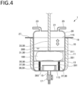
- Fig. 2 is a partial cross-sectional view of the reinforcing-fiber recovery reactor shown in Fig. 1 .
- a reinforcing-fiber recovery reactor 1 shown in Fig. 1 is used to recover reinforcing fibers from a fiber-reinforced resin material by a solvent method.
- the fiber-reinforced resin material is a resin material reinforced by embedded reinforcing fibers such as carbon fibers. Details of the fiber-reinforced resin material will be described later.
- a reinforcing-fiber recovery reactor 1 includes a reaction vessel 10, a lid 20, a fixing mechanism 30 and a support base 40. In the following description, each component of the reinforcing-fiber recovery reactor 1 will be specifically described in order.
- the reaction vessel 10 is capable of accommodating a fiber-reinforced resin material and a solvent. As shown in Fig. 2 , the reaction vessel 10 includes a reaction vessel body 11, a temperature control jacket 13, a drain port 15, a valve 17 and a flange 19.
- the reaction vessel body 11 is a bottomed cylindrical vessel having a bottom 113 at the bottom and an opening 115 at the top.
- the reaction vessel body 11 includes an accommodation space 111 capable of accommodating a fiber-reinforced resin material and a solvent. Materials required for reaction of a fiber-reinforced resin material, a solvent, and the like are introduced into the accommodation space 111 of the reaction vessel body 11 through the opening 115.
- the temperature control jacket 13 is disposed covering the outer peripheral side surface of the reaction vessel body 11.
- the temperature control jacket 13 is capable of controlling the temperature of the contents by heating and/or cooling the contents accommodated in the reaction vessel body 11.
- a heating medium such as water, is passed through the temperature control jacket 13 to exchange heat to thereby control the temperature of the contents.
- the temperature control jacket 13 may be a heating means such as an electric heater.
- the drain port 15 is provided in the bottom 113 of the reaction vessel body 11, and liquid such as a treatment solution can be discharged from the accommodation space 111 of the reaction vessel body 11 through the drain port 15. Further, a valve 17 is provided in the drain port 15, and opening and closing of the drain port 15 can be controlled by operating the valve 17.
- the flange 19 is a disk-shaped member that protrudes from the outer peripheral edge of the reaction vessel body 11 near the opening 115.
- the flange 19 is configured to abut a flange 27 of the lid 20, which will be described later, during reaction to prevent, together with the flange 27, leakage of the contents of the reaction vessel body 11. Further, by fixing the flange 19 and the flange 27 to each other, the lid 20 can be fixed to the reaction vessel body 11.
- the lid 20 is a detachable lid capable of opening and closing the reaction vessel 10, and can close the reaction vessel 10 by being disposed covering the opening 115.
- the lid 20 includes a lid body 21, an injection port 23, an exhaust port 25 and a flange 27.
- the lid body 21 is a main part of the lid 20, and has a shape of an inverted bowl.
- a through hole is formed in a center part of the lid body 21, and a control member 33 of the fixing mechanism 30, which will be described later, extends through the through hole.
- the injection port 23 and the exhaust port 25 are attached to the lid body 21.
- the injection port 23 is a pipe for injecting a treatment solution such as a solvent.
- the exhaust port 25 is a pipe for removing an excess gas, such as vapor, generated in use of the reaction vessel 10.
- the injection port 23 and the exhaust port 25 are provided on the top of the lid body 21.
- the present invention is not limited to the illustrated embodiment, and the injection port 23 and the exhaust port 25 can be attached to any position of the lid body 21 or any position of the reaction vessel 10.
- a plurality of injection ports 23 and exhaust ports 25 may be provided according to the application.
- the flange 27 is a disk-shaped member that protrudes from the outer peripheral edge of the lid body 21 on the side of the opening 115 of the reaction vessel 10.
- the flange 27 is configured to abut the flange 19 of the reaction vessel 10 during reaction to prevent, together with the flange 19, leakage of the contents of the reaction vessel body 11.
- the fixing mechanism 30 fixes the fiber-reinforced resin material by pressing it in use of the reinforcing-fiber recovery reactor 1.
- the fixing mechanism 30 includes a pressing member 31, a control member 33, a support member 35, an elastic member 37 and a regulating member 39.
- the pressing member 31 is disposed in the accommodation space 111 of the reaction vessel 10 in use of the reinforcing-fiber recovery reactor 1.
- the pressing member 31 has a plate shape having a pressing surface 311 for pressing the fiber-reinforced resin material.
- the pressing member 31 is disposed with the pressing surface 311 being horizontal and substantially parallel to a support surface 351 of the support member 35.
- the position of the pressing member 31 having the above configuration is controlled by the control member 33 so that the pressing surface 311 can be pressed against the fiber-reinforced resin material.
- the area of the pressing surface 311 of the pressing member 31 is not particularly limited, but may be, for example, 10% or more and 90% or less, preferably 30% or more and 50% or less, of the cross-sectional area of the accommodation space 111 parallel to the pressing surface 311. Accordingly, while the fiber-reinforced resin material is fixed by the pressing member 31, a treatment solution can easily flow in the accommodation space 111, which facilitates permeation of the treatment solution into the fiber-reinforced resin material.
- the control member 33 is a rod-shaped member with one end connected to the pressing member 31.
- the other end of the control member 33 penetrates the lid body 21 and is connected to a driving device (not shown).
- a driving device not shown.
- the control member 33 moves in a direction perpendicular to the pressing surface 311 (i.e., vertically in the drawing)
- the pressing member 31 can move in the direction perpendicular to the pressing surface 311.
- the support member 35 is disposed under the control member 33 in the accommodation space 111.
- the support member 35 has a plate shape and is disposed with the support surface 351 on one side facing the pressing surface 311.
- the support member 35 supports the fiber-reinforced resin material between the support surface 351 and the pressing member 31.
- the fiber-reinforced resin material can be fixed between the pressing member 31 and the support member 35.
- the area of the support surface 351 of the support member 35 is not particularly limited, but may be, for example, 10% or more and 90% or less, preferably 30% or more and 50% or less, of the cross-sectional area of the accommodation space 111 parallel to the support surface 351. Accordingly, while the fiber-reinforced resin material is fixed by the support member 35, a treatment solution can easily flow in the accommodation space 111, which facilitates permeation of the treatment solution into the fiber-reinforced resin material.
- the elastic member 37 is disposed between the support member 35 and the bottom 113 of the reaction vessel body 11 to support the support member 35.
- the elastic member 37 is a compression coil spring. Due to such an elastic member 37 supporting the support member 35, the support member 35 can move downward according to the pressing force from the pressing member 31. This prevents excessive pressure from being applied to the fiber-reinforced resin material, and suppresses damage to the reinforcing fibers in the fiber-reinforced resin material. Further, due to the elastic member 37 being provided, the support member 35 can reciprocate corresponding to reciprocation of the pressing member 31. As the pressing member 31 and the support member 35 reciprocate, the treatment solution in the accommodation space 111 is agitated.
- the regulating member 39 includes a regulating plate 391 and a connecting member that connects the regulating plate 391 to the bottom 113 of the reaction vessel body 11.
- the regulating plate 391 is fixed substantially parallel to the support member 35 between the support member 35 and the bottom 113 of the reaction vessel body 11.
- the support member 35 moves downward, it abuts the regulating plate 391 of the regulating member 39, whereby the downward movement of the support member 35 is regulated. That is, the regulating member 39 controls the position to which the support member 35 can move downward. Since the fixing mechanism 30 has the regulating member 39, it is possible to compress the fiber-reinforced resin material between the pressing member 31 and the support member 35 by moving the pressing member 31 downward.
- the support base 40 shown in Fig. 1 is a base supporting the reaction vessel 10.
- the support base 40 includes a support base body 41 and a rotary shaft 43.
- the support base body 41 has pillar-shaped legs and is placed on the ground.
- the rotary shaft 43 is rotatably connected to the upper part of the support base body 41 and the reaction vessel 10. This enables tilting of the reaction vessel 10. As a result, the opening 115 of the reaction vessel 10 can be tilted downward, which facilitates introduction of the fiber-reinforced resin material and removal of the reinforcing fibers after reaction.
- a reaction can be performed while the fixing mechanism 30 presses and fixes the fiber-reinforced resin material. Accordingly, when the fiber-reinforced resin material is subjected to treatment with the treatment solution containing the solvent, the shape of the reinforcing fibers in the fiber-reinforced resin material becomes less likely to be deformed. In particular, even after the resin component in the fiber-reinforced resin material is dissolved and the reinforcing fibers are exposed during treatment, the reinforcing fibers are less likely to be entangled since the reinforcing fibers are fixed by the fixing mechanism 30.
- the treatment solution can uniformly permeate through the reinforcing fibers in the fiber-reinforced resin material, and thus the dissolution reaction of the resin component can uniformly proceed.
- a reaction can be performed while the fixing mechanism 30 presses and fixes the fiber-reinforced resin material. Therefore, a variety of fiber-reinforced resin materials can be subjected to treatment regardless of the size and shape. For example, finely cut fiber-reinforced resin materials or large prepreg sheets can be subjected to treatment to recover recycled reinforcing fibers.
- the reinforcing-fiber recovery reactor 1 can also be used for washing and deliquoring the recovered recycled reinforcing fibers. Therefore, a plurality of steps for recovering recycled reinforcing fibers can be performed using the reinforcing-fiber recovery reactor 1 without changing the device.
- a treatment solution can be agitated as the pressing member 31 reciprocates.
- the support member 35 can reciprocate as the pressing member 31 reciprocates, agitation can be performed while the fiber-reinforced resin material is fixed.
- the method of producing recycled reinforcing fibers according to the present invention includes a dissolving step of subjecting a fiber-reinforced resin material containing reinforcing fibers and a resin component to treatment with a treatment solution containing a solvent to dissolve at least part of the resin component in the treatment solution, wherein the fiber-reinforced resin material is subjected to treatment with the treatment solution in the dissolving step while being pressed and fixed.
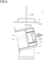
- Figs. 3 to 6 are partial cross-sectional views illustrating an example of operation of the reinforcing-fiber recovery reactor in the method of producing recycled reinforcing fibers according to the present embodiment. In the following description, each step in the method of producing recycled reinforcing fibers according to the present embodiment will be described.
- a fiber-reinforced resin material 100 used in the dissolving step is prepared.
- the fiber-reinforced resin material is a resin material reinforced by embedded reinforcing fibers.
- the fiber-reinforced resin material 100 include, but are not limited to, carbon fiber reinforced plastics (CFRP), glass fiber reinforced plastics (GFRP), glass-mat reinforced thermoplastics (GMT), aramid-fiber-reinforced plastics (AFRP), Kevlar fiber reinforced plastics (KFRP), Dyneema fiber-reinforced plastics (DFRP), basalt fiber reinforced plastics, boron fiber reinforced plastics, and prepregs thereof.
- CFRP carbon fiber reinforced plastics
- GFRP glass fiber reinforced plastics
- GTT glass-mat reinforced thermoplastics
- AFRP aramid-fiber-reinforced plastics
- KFRP Kevlar fiber reinforced plastics
- DFRP Dyneema fiber-reinforced plastics
- basalt fiber reinforced plastics boro
- the reinforcing fibers in the fiber-reinforced resin material 100 may be in the form of fiber bundles (tows) in which a plurality of reinforcing fibers are aligned in one direction, or in the form of a woven fabric or a non-woven fabric in which fiber bundles of reinforcing fibers are used as warp and weft, or the reinforcing fibers may be arranged at random positions and orientations.
- the method according to the present embodiment is suitable for recovering reinforcing fibers from the fiber-reinforced resin material containing reinforcing fibers in the form of a fiber bundle or a woven fabric.
- the reinforcing fibers may be in the form of chips, and examples thereof include chopped fibers obtained by cutting fiber bundles, chips of a woven fabric, and the like.
- the resin component contained in the fiber-reinforced resin material 100 is not particularly limited, and may be, for example, either a thermosetting resin or a thermoplastic resin.
- the thermosetting resin may be uncured or may be a cured product.
- thermosetting resin examples include, but are not limited to, epoxy resins, unsaturated polyester resins, vinyl ester resins, phenol resins, cyanate resins, polyimide resins, melamine resins, urethane resins, polycarbonate resins, polyacetal resins, and the like, and these can be used singly or in combination of two or more for the resin component.
- thermoplastic resin examples include, but are not limited to, polyamides, polyolefins, polyesters, polycarbonates, acrylic resins, acrylonitrile-butadiene-styrene copolymers, polyether ketones, polyphenylene sulfides, and the like, and these can be used singly or in combination of two or more for the resin component.
- the fiber-reinforced resin material 100 may have a sheet shape, or may be in the form of cut chips.
- the method according to the present embodiment can be suitably used for the sheet-shaped fiber-reinforced resin material 100, from which it has been difficult to recover reinforcing fibers.
- the size of the fiber-reinforced resin material 100 is not particularly limited as long as it can be accommodated in the accommodation space 111 of the reaction vessel 10.
- the length of each piece of the fiber-reinforced resin material 100 may be, for example, 100 mm or more, and preferably 500 mm or more and 3,000 mm or less. More specifically, as the fiber-reinforced resin material 100, for example, a fiber-reinforced resin material sheet having a laminate thickness of approximately 300 mm and a size of 1,000 mm ⁇ 500 mm can be used.
- the prepared fiber-reinforced resin material 100 is subjected to treatment with a treatment solution 200 containing a solvent so that at least part of a resin component is dissolved in the treatment solution 200.
- the fiber-reinforced resin material 100 and the treatment solution 200 are introduced into the accommodation space 111 of the reaction vessel 10 of the reinforcing-fiber recovery reactor 1 as shown in Figs. 3 and 4 , and subjected to treatment in the reaction vessel 10.
- the treatment solution 200 will be described first, and then a specific procedure will be described.
- the treatment solution 200 in this step contains at least a solvent, and at least part of the resin component in the fiber-reinforced resin material 100 is dissolved.
- the term "resin component is dissolved” as used herein means not only that the resin component itself directly dissolves in the treatment solution 200, but also that the resin component decomposes to produce a reaction product, and the reaction product dissolves in the treatment solution 200.
- the solvent is a main component of the treatment solution 200.
- the solvent is not particularly limited as long as it can dissolve the resin component of the fiber-reinforced resin material 100 or a reaction product in this step, and may be, for example, water and/or various organic solvents.
- organic solvents examples include, but are not limited to, alcohol-based solvents, ether-based solvents, ester-based solvents, ketone-based solvents, amide-based solvents, aromatic hydrocarbons, halogenated aromatic hydrocarbons, halogenated aliphatic hydrocarbons, and the like, and these can be used singly or in combination of two or more.
- alcohol-based solvents examples include aliphatic alcohol-based solvents, aromatic alcohol-based solvents, glycol-based solvents and other polyhydric alcohols such as glycerin.
- aliphatic alcohol-based solvents include acyclic aliphatic alcohols such as 1-butanol, 2-butanol, 2-methyl-1-propanol, 2-methyl-2-propanol, 1-pentanol, 2-pentanol, 3-pentanol, 2-methyl-1-butanol, 2-methyl-2-butanol, 3-methyl-1-butanol, 3-methyl-2-butanol, 2,2-dimethyl-1-propanol, 1-hexanol, 2-hexanol, 3-hexanol, 2-ethylhexanol, 2-methyl-1-pentanol, 4-methyl-2-pentanol, 2-ethyl-1-butanol, 1-heptanol, 2-heptanol, 3-heptanol, dodecanol, methanol and ethanol; and alicyclic alcohols such as cyclohexanol, 1-methylcyclohexanol, 2-methylcyclohexan
- aromatic alcohol-based solvents examples include phenol, cresol, benzyl alcohol and phenoxyethanol.
- glycol-based solvents examples include ethylene glycol, ethylene glycol monomethyl ether, ethylene glycol monoethyl ether, ethylene glycol monopropyl ether, ethylene glycol monobutyl ether, diethylene glycol, diethylene glycol monomethyl ether, diethylene glycol monoethyl ether, diethylene glycol monopropyl ether, diethylene glycol monobutyl ether, triethylene glycol, triethylene glycol monomethyl ether, triethylene glycol monoethyl ether, tetra ethylene glycol, polyethylene glycol (molecular weight 200 to 400), 1,2-propanediol, 1,3-propanediol, 1,2-butanediol, 1,3-butanediol, 1,4-butanediol, 2,3-butanediol, 1,5-pentanediol and dipropylene glycol.
- ether-based solvents examples include aliphatic ethers such as dimethyl ether, diethyl ether, ethyl methyl ether, dipropyl ether, diisopropyl ether, dibutyl ether and dihexyl ether; cyclic ethers such as 1,3-dioxolane, 1,4-dioxane, tetrahydrofuran and furan; and aromaticcontaining ethers such as anisole, phenetole, diphenyl ether and benzofuran.
- aliphatic ethers such as dimethyl ether, diethyl ether, ethyl methyl ether, dipropyl ether, diisopropyl ether, dibutyl ether and dihexyl ether
- cyclic ethers such as 1,3-dioxolane, 1,4-dioxane, tetrahydrofuran and furan
- aromaticcontaining ethers such as anisole
- ester-based solvents examples include methyl formate, ethyl formate, propyl formate, butyl formate, isobutyl formate, pentyl formate, methyl acetate, ethyl acetate, propyl acetate, isopropyl acetate, butyl acetate, isobutyl acetate, pentyl acetate, isopentyl acetate, 3-methoxybutyl acetate, 2-ethylbutyl acetate, 2-ethylhexyl acetate, cyclohexyl acetate, benzyl acetate, methyl propionate, ethyl propionate, butyl propionate, isopentyl propionate, methyl lactate, ethyl lactate, butyl lactate, methyl butyrate, ethyl butyrate, butyl butyrate, isopentyl butyrate, isobutyl
- ketone-based solvents examples include acetone, methyl ethyl ketone, 2-pentanone, 3-pentanone, 2-hexanone, methyl isobutyl ketone, 2-heptanone, 4-heptanone, diisobutyl ketone, cyclohexanone, methylcyclohexanone, phorone, isophorone, acetylacetone, acetophenone, diethylketone and diacetone alcohol.
- amide-based solvents examples include formamide, N-methylformamide, N,N-dimethylformamide, N,N-diethylformamide, acetamide, N-methylacetamide, N,N-dimethylacetamide, 2-pyrrolidone, N-methyl-2-pyrrolidone, caprolactam and carbamic acid ester.
- aromatic hydrocarbons examples include benzene, toluene and xylene.
- halogenated aromatic hydrocarbons examples include orthochlorophenol and orthodichlorobenzene.
- halogenated aliphatic hydrocarbons examples include chloroform and methylene chloride.
- the solvent content in the treatment solution 200 is not particularly limited, but may be, for example, 0.01 mass% or more and 100 mass% or less, preferably 40 mass% or more and 60 mass% or less, and more preferably 80 mass% or more and 100 mass% or less.
- the treatment solution 200 may contain a catalyst.
- the catalyst is not particularly limited as long as it catalyzes the dissolution of the resin component in the fiber-reinforced resin material 100, and examples thereof include acidic substances and basic substances. These substances can improve the solubility of the resin component in a solvent, for example, by adding a hydrogen ion, a hydroxide ion, or the like to a functional group of the resin component, or by decomposing the resin component.
- the solvent contains a protic solvent, especially water, the catalytic action of acidic substances and basic substances is further improved.
- Examples of the acidic substance include inorganic acids, organic acids, salts thereof, and mixtures thereof.
- Examples of the inorganic acids include nitric acid, sulfuric acid, hydrochloric acid and phosphoric acid, and these can be used singly or in combination of two or more.
- Examples of the phosphate include orthophosphate, metaphosphate, hypophosphate, phosphite, hypophosphite, pyrophosphate, trimetaphosphate, tetrametaphosphate and pyrophosphite.
- Examples of the organic acids include formic acid, acetic acid, citric acid, succinic acid and oxalic acid.
- salts of inorganic acids or organic acids include salts of alkali metals (for example, sodium, potassium, cesium, rubidium, or the like) and/or alkaline earth metals (for example, beryllium, magnesium, calcium, strontium, barium, or the like) of the inorganic acids or organic acids described above.
- alkali metals for example, sodium, potassium, cesium, rubidium, or the like
- alkaline earth metals for example, beryllium, magnesium, calcium, strontium, barium, or the like
- inorganic acids in particular, nitric acid, sulfuric acid, hydrochloric acid and phosphoric acid are preferred since they are easily available and tend to contribute to promotion of the dissolution of the resin component.
- the content of the acidic substance can be appropriately selected depending on the type of the acidic substance used, the type of the solvent in the treatment solution 200, and the resin component in the target fiber-reinforced resin material 100.
- the content of the acidic substance in the treatment solution 200 may be, for example, 0.01 mass% or more and 100 mass% or less, and in particular 10 mass% or more and 50 mass% or less.
- Examples of the basic substances include inorganic basic substances such as hydroxides, carbonates, hydrogen carbonates, sulfates, sulfites and nitrates of lithium, alkali metals and alkaline earth metals; and amine compounds such as dimethylamine and diethylamine, and these can be used singly or in combination of two or more.
- Examples of the alkali metals include sodium, potassium, cesium and rubidium.
- Examples of the alkaline earth metals include beryllium, magnesium, calcium, strontium and barium.
- the basic substance preferably contains one or more selected from the group consisting of sodium hydroxide, potassium hydroxide, sodium hydrogen carbonate, sodium carbonate, potassium hydrogen carbonate and potassium carbonate.
- the content of the basic substance can be appropriately selected depending on the type of the basic substance used, the type of the solvent in the treatment solution 200, and the resin component in the target fiber-reinforced resin material 100.
- the content of the basic substance in the treatment solution 200 may be, for example, 0.01 mass% or more and 100 mass% or less, and in particular 10 mass% or more and 50 mass% or less.
- the fiber-reinforced resin material 100 is introduced into the accommodation space 111 of the reaction vessel 10.
- the fiber-reinforced resin material 100 is disposed between the pressing member 31 and the support member 35 of the fixing mechanism 30.
- the treatment solution 200 is injected into the accommodation space 111 through the injection port 23.
- the treatment solution 200 may be collectively injected into the accommodation space 111, or the components constituting the treatment solution 200 may be separately injected into the accommodation space 111.
- the fixing mechanism 30 may not necessarily fix the fiber-reinforced resin material 100.
- the fiber-reinforced resin material 100 is subjected to treatment with the treatment solution.
- treatment with the treatment solution 200 is performed while the pressing member 31 of the fixing mechanism 30 presses and fixes the fiber-reinforced resin material 100.
- the pressure of the pressing surface 311 when the pressing member 31 presses the fiber-reinforced resin material 100 is not particularly limited, but may be, for example, 8.5 ⁇ 10 -5 Pa or more and 8.5 Pa or less, and preferably 8.5 ⁇ 10 -4 Pa or more and 8.5 -1 Pa or less.
- the pressing member 31 is preferably reciprocated vertically to agitate the treatment solution 200.
- the support member 35 supported by the elastic member 37 reciprocates in accordance with the reciprocation of the pressing member 31. Therefore, the fiber-reinforced resin material 100 is fixed between the pressing member 31 and the support member 35 of the fixing mechanism 30 even when the pressing member 31 is reciprocated.
- the treatment solution 200 can be agitated while the fiber-reinforced resin material 100 is fixed.
- a general agitating blade or the like is used to agitate a treatment solution, but in this case, the reinforcing fibers exposed from the fiber-reinforced resin material may be damaged by the agitating blade, or the reinforcing fibers may be entangled with the agitating blade. Therefore, it has been difficult to recover the reinforcing fibers while maintaining the shape and orientation of the reinforcing fibers.
- agitation is performed while the fixing mechanism 30 fixes the fiber-reinforced resin material 100 to thereby suppress the above problem. Accordingly, it is possible to recover the reinforcing fibers while maintaining the shape and orientation of the reinforcing fibers.
- the moving distance (one-way distance) of the pressing member 31 that reciprocates when agitating the treatment solution 200 using the fixing mechanism 30 is not particularly limited, but may be, for example, 5 mm or more and 1,000 mm or less, and preferably 50 mm or more and 300 mm or less.
- the temperature of the treatment solution 200 during treatment is not particularly limited and varies depending on the type of the treatment solution 200, and may be, for example, 30°C or more and 300°C or less, and preferably 50°C or more and 100°C or less.
- the temperature of the treatment solution 200 is adjusted by operating the temperature control jacket 13.
- the treatment time with the treatment solution 200 is not particularly limited, and may be 1 minute or more and 1,440 minutes or less, and preferably 10 minutes or more and 60 minutes or less after the target temperature is reached.
- the treatment with the treatment solution 200 may be performed under normal pressure, reduced pressure, or increased pressure.
- the pressure may be, for example, 0.11 MPa or more and 7.0 MPa or less, and in particular 0.11 MPa or more and 2.0 MPa or less.
- the treatment with the treatment solution 200 is preferably performed under normal pressure.
- valve 17 is operated to open the drain port 15, as shown in Fig. 5 , so that the treatment solution 200 is discharged from the drain port 15.
- the pressing member 31 preferably presses the fiber-reinforced resin material 100 to compress the fiber-reinforced resin material 100. This enables efficient deliquoring. Specifically, when the pressing member 31 moves downward, the support member 35 moves accordingly to a position where it abuts the regulating member 39. As the pressing member 31 further presses the fiber-reinforced resin material 100 with an appropriate pressure, deliquoring can be performed.
- washing is performed as necessary. Washing can be performed by exposing the fiber-reinforced resin material 100 to a cleaning solution. Specifically, washing can be performed by replacing the treatment solution 200 with a cleaning solution in the above dissolving step and deliquoring step. The temperature of the cleaning solution and the washing time during washing can be appropriately set.
- Washing can be performed while the fixing mechanism 30 fixes the fiber-reinforced resin material 100. Accordingly, it is possible to wash and recover the reinforcing fibers while maintaining the shape and orientation of the reinforcing fibers contained in the fiber-reinforced resin material 100.
- cleaning solution examples include water and various organic solvents described above as the solvent of the treatment solution 200, and these can be used singly or in combination of two or more.
- the cleaning solution may contain an acidic substance or a basic substance. These substances can be used to adjust the liquid properties so that a resin component remaining in the fiber-reinforced resin material 100 and a reaction product thereof can be removed.
- Each of the dissolving step, deliquoring step and washing step described above can be performed multiple times as necessary. For example, after the dissolving step and deliquoring step are repeated multiple times, the washing step may be performed. Alternatively, for example, after the dissolving step is performed multiple times, the deliquoring step may be performed, and then the washing step may be performed a required number of times. Alternatively, for example, the dissolving step, deliquoring step and washing step may be performed in this order a required number of times.
- the fiber-reinforced resin material 100 may be dried. Drying may be performed, for example, by circulating a gas in the accommodation space 111 of the reaction vessel 10 with an air supply means (not shown).
- the circulated gas is not particularly limited, but is preferably air or an inert gas such as nitrogen from the viewpoint of safety.
- the fiber-reinforced resin material 100 may be heated. This accelerates drying. Heating may be performed, for example, by using the temperature control jacket 13 or by introducing a heated gas into the reaction vessel 10.
- the temperature of the gas during heating may be, for example, 0°C or more and 400°C or less, and preferably 80°C or more and 110°C or less.
- Heating may be performed while the fixing mechanism 30 fixes the fiber-reinforced resin material 100. Accordingly, it is possible to dry the reinforcing fibers while maintaining the shape and orientation of the reinforcing fibers contained in the fiber-reinforced resin material 100.
- the reinforcing fibers are recovered from the fiber-reinforced resin material 100 to obtain recycled reinforcing fibers.
- the opening 115 of the reaction vessel 10 is tilted downward around the rotary shaft 43 of the support base 40 so that the recycled reinforcing fibers can be taken out easily.
- recycled reinforcing fibers can be obtained.
- the resin component in the fiber-reinforced resin material 100 is dissolved in the treatment solution 200 containing a solvent while the fixing mechanism 30 presses and fixes the fiber-reinforced resin material 100. Accordingly, when the fiber-reinforced resin material 100 is subjected to treatment with the treatment solution 200 containing the solvent, the shape of the reinforcing fibers in the fiber-reinforced resin material 100 becomes less likely to be deformed. In particular, even after the resin component in the fiber-reinforced resin material 100 is dissolved and the reinforcing fibers are exposed during treatment, the reinforcing fibers are less likely to be entangled since they are fixed.
- the treatment solution can uniformly permeate through the reinforcing fibers in the fiber-reinforced resin material 100, and thus the dissolution reaction of the resin component can uniformly proceed.
- a reaction can be performed while the fixing mechanism 30 presses and fixes the fiber-reinforced resin material. Therefore, a variety of fiber-reinforced resin materials 100 can be subjected to treatment regardless of the size and shape. For example, finely cut fiber-reinforced resin materials or large prepreg sheets can be subjected to treatment to recover recycled reinforcing fibers.
- the support member 35 supported by the elastic member 37 is provided, but the present invention is not limited thereto, and the support member 35 may be omitted, for example, as in a reinforcing-fiber recovery reactor 1A shown in Fig. 7 .
- the bottom 113 of the reaction vessel body 11 functions as a support member, and the pressing member 31, the control member 33 and the bottom 113 constitute a fixing mechanism 30A.
- the fixing mechanism 30 is configured such that the pressing member 31 and the support member 35 press and fix the fiber-reinforced resin material 100 in the vertical direction, but the present invention is not limited thereto, and the fixing mechanism may press and fix the fiber-reinforced resin material in any direction.
- the pressing member and the support member may be disposed to press and fix the fiber-reinforced resin material in the horizontal direction.
- the pressing member 31 and the support member 35 have a plate shape, but the present invention is not limited thereto.
- holes may be formed in the pressing member and the support member. This reduces the fluid resistance during agitation.
- the pressing member and the support member may be mesh sheets.
- agitation of the treatment solution 200 is performed by vertically reciprocating the pressing member 31 and the support member 35
- the reaction vessel may be provided with an agitating device at a position that does not come into contact with the fiber-reinforced resin material.
- agitation may be performed by moving the reaction vessel while fixing the position of the fixing mechanism.
- the mode of motion of the reaction vessel is not particularly limited, and may be, for example, a reciprocating motion in the vertical direction and/or horizontal direction or a rotary motion.
- the elastic member 37 is described as a compression coil spring, but the present invention is not limited thereto, and the elastic member may be formed of any elastic member.
- examples of such an elastic member include a leaf spring such as a laminated leaf spring and a thin leaf spring, a torsion spring, a volute spring, and a polymer elastic body such as rubber or elastomer.
- reaction vessel 10 and the reaction vessel body 11 are described as having a cylindrical shape, but the present invention is not limited thereto.
- the shape of the reaction vessel body 11 may be changed so that the accommodation space has a substantially rectangular parallelepipied shape.
Landscapes
- Engineering & Computer Science (AREA)
- Environmental & Geological Engineering (AREA)
- Mechanical Engineering (AREA)
- Health & Medical Sciences (AREA)
- Chemical & Material Sciences (AREA)
- Chemical Kinetics & Catalysis (AREA)
- General Chemical & Material Sciences (AREA)
- General Health & Medical Sciences (AREA)
- Toxicology (AREA)
- Separation, Recovery Or Treatment Of Waste Materials Containing Plastics (AREA)
- Processing Of Solid Wastes (AREA)
Applications Claiming Priority (2)
| Application Number | Priority Date | Filing Date | Title |
|---|---|---|---|
| JP2020200195 | 2020-12-02 | ||
| PCT/JP2021/043454 WO2022118756A1 (ja) | 2020-12-02 | 2021-11-26 | 補強繊維回収用反応装置および再生補強繊維の製造方法 |
Publications (2)
| Publication Number | Publication Date |
|---|---|
| EP4257254A1 true EP4257254A1 (de) | 2023-10-11 |
| EP4257254A4 EP4257254A4 (de) | 2024-06-19 |
Family
ID=81853902
Family Applications (1)
| Application Number | Title | Priority Date | Filing Date |
|---|---|---|---|
| EP21900510.5A Pending EP4257254A4 (de) | 2020-12-02 | 2021-11-26 | Reaktorvorrichtung zur rückgewinnung von verstärkungsfasern und herstellungsverfahren für recycelte verstärkungsfasern |
Country Status (6)
| Country | Link |
|---|---|
| US (1) | US20240025084A1 (de) |
| EP (1) | EP4257254A4 (de) |
| JP (1) | JP7222154B2 (de) |
| KR (1) | KR102725685B1 (de) |
| CN (1) | CN116648314A (de) |
| WO (1) | WO2022118756A1 (de) |
Families Citing this family (4)
| Publication number | Priority date | Publication date | Assignee | Title |
|---|---|---|---|---|
| JP7783999B2 (ja) * | 2022-09-21 | 2025-12-10 | 株式会社イノアックコーポレーション | ポリウレタンフォームの分解処理装置及びポリウレタンフォームの分解処理方法 |
| JP2024067210A (ja) * | 2022-11-04 | 2024-05-17 | トヨタ自動車株式会社 | 炭素繊維回収方法 |
| CN116274258B (zh) * | 2023-05-12 | 2024-04-19 | 江苏苏洁环卫装备有限公司 | 一种垃圾房的喷淋式垃圾除臭设备 |
| JP2026026066A (ja) * | 2024-08-02 | 2026-02-16 | ロックペイント株式会社 | マテリアルリサイクル方法 |
Family Cites Families (19)
| Publication number | Priority date | Publication date | Assignee | Title |
|---|---|---|---|---|
| US4249562A (en) * | 1978-11-06 | 1981-02-10 | King Lloyd H Sr | Inline dispersal valve |
| JP3230196B2 (ja) * | 1993-07-15 | 2001-11-19 | 弘次 青木 | 樹脂廃棄物の処理装置 |
| CA2105142C (en) * | 1993-08-30 | 2001-03-13 | Shigetomi Komatsu | Method of recovering polystyrene waste materials and its apparatus for dissolving polystyrene waste materials |
| JP2001040134A (ja) * | 1999-07-28 | 2001-02-13 | Bio Venture Bank Kk | 発泡スチロール減溶化装置 |
| JP2001240697A (ja) * | 2000-02-29 | 2001-09-04 | Sanesu:Kk | 溶媒触媒法による炭素繊維強化プラスチックからの炭素繊維回収方法 |
| JP3072696U (ja) * | 2000-04-20 | 2000-10-24 | 株式会社阿部鉄工所 | 発泡スチロールの溶解・回収装置 |
| JP4595847B2 (ja) * | 2006-03-17 | 2010-12-08 | 日立化成工業株式会社 | 繊維強化プラスチックに含まれる繊維および充填材の分離回収方法 |
| JP5347056B2 (ja) * | 2011-08-30 | 2013-11-20 | カーボンファイバーリサイクル工業株式会社 | 再生炭素繊維の製造装置及び再生炭素繊維の製造方法 |
| JP5816898B2 (ja) * | 2012-03-28 | 2015-11-18 | 国立大学法人静岡大学 | リサイクル繊維の製造方法およびリサイクル繊維製造システム |
| WO2014058615A2 (en) * | 2012-10-09 | 2014-04-17 | Waters Technologies Corporation | Apparatus and method for analyte extraction |
| DE102013200482A1 (de) * | 2013-01-15 | 2014-07-17 | Siemens Aktiengesellschaft | Verfahren zur Wiedergewinnung von Verstärkungsfasern aus faserverstärkten Kunststoffen |
| US20170081785A1 (en) * | 2015-09-22 | 2017-03-23 | Caterpillar Inc. | Carbon fiber reclamation from composite materials |
| WO2017052229A1 (ko) * | 2015-09-23 | 2017-03-30 | 롯데케미칼 주식회사 | 프리프레그 재활용 방법 |
| KR101663796B1 (ko) * | 2015-09-23 | 2016-10-07 | 롯데케미칼 주식회사 | 섬유 회수 장치 및 이를 이용한 프리프레그 재활용 방법 |
| KR101801788B1 (ko) * | 2015-12-11 | 2017-11-28 | 한국과학기술연구원 | 열경화성 수지 복합 재료로부터 섬유 집합체를 회수하는 방법 및 장치, 이로부터 회수된 섬유 집합체 |
| JP6694862B2 (ja) * | 2017-11-09 | 2020-05-20 | 三菱重工業株式会社 | 強化繊維再生方法 |
| JP7148109B2 (ja) * | 2018-04-18 | 2022-10-05 | 株式会社ジンテク | 積層したチップ状または板状プラスチック複合材料の処理方法 |
| JP2020011482A (ja) | 2018-07-20 | 2020-01-23 | 日立化成株式会社 | 再生材料の製造方法、複合材料の処理方法及び炭素繊維 |
| US11167451B2 (en) * | 2018-08-03 | 2021-11-09 | The Boeing Company | Lewis base-mediated recovery of fibers from fiber reinforced polymers |
-
2021
- 2021-11-26 KR KR1020237022201A patent/KR102725685B1/ko active Active
- 2021-11-26 WO PCT/JP2021/043454 patent/WO2022118756A1/ja not_active Ceased
- 2021-11-26 JP JP2022566889A patent/JP7222154B2/ja active Active
- 2021-11-26 EP EP21900510.5A patent/EP4257254A4/de active Pending
- 2021-11-26 CN CN202180079668.8A patent/CN116648314A/zh active Pending
- 2021-11-26 US US18/039,725 patent/US20240025084A1/en active Pending
Also Published As
| Publication number | Publication date |
|---|---|
| WO2022118756A1 (ja) | 2022-06-09 |
| EP4257254A4 (de) | 2024-06-19 |
| JP7222154B2 (ja) | 2023-02-14 |
| CN116648314A (zh) | 2023-08-25 |
| US20240025084A1 (en) | 2024-01-25 |
| JPWO2022118756A1 (de) | 2022-06-09 |
| KR102725685B1 (ko) | 2024-11-05 |
| KR20230107389A (ko) | 2023-07-14 |
Similar Documents
| Publication | Publication Date | Title |
|---|---|---|
| EP4257254A1 (de) | Reaktorvorrichtung zur rückgewinnung von verstärkungsfasern und herstellungsverfahren für recycelte verstärkungsfasern | |
| JP7240567B2 (ja) | 再生補強繊維の製造方法 | |
| JP4686991B2 (ja) | 炭素材料/酸無水物硬化エポキシ樹脂複合材料の分離方法 | |
| EP3389972A1 (de) | Wiederverwertung von materialien auf kohlenstofffaserbasis | |
| JP2005255899A (ja) | 炭素材料/酸無水物硬化エポキシ樹脂複合材料の処理液および分離方法 | |
| US20180371204A1 (en) | Method of separating inorganic material, method of producing reprocessed material and method of removing organic substance | |
| JP6729593B2 (ja) | 炭素繊維不織布、炭素繊維不織布の製造方法、炭素繊維多層布、及び複合材料 | |
| WO2024075786A1 (ja) | 再生補強繊維の製造方法 | |
| JP7470450B1 (ja) | 再生補強繊維の製造方法 | |
| JPWO2017154099A1 (ja) | 有機材料除去装置 | |
| CN103275350B (zh) | 环氧树脂/纤维复合材料预处理分层的方法 | |
| JP6270100B2 (ja) | 不飽和ポリエステルの解重合方法、およびその解重合方法を用いた不飽和ポリエステルの原料の回収方法 | |
| JP2017052865A (ja) | 未硬化エポキシ樹脂複合材料の溶解方法 | |
| TW202611196A (zh) | 再生增強纖維的製造方法 | |
| JP2019044100A (ja) | 有機材料除去装置 | |
| US10773422B2 (en) | Method of separating inorganic material, method of producing reprocessed material and method of removing organic substance | |
| Salmela | Chemical recycling of carbon fibre-reinforced epoxy composites | |
| WO2017154100A1 (ja) | 有機材料除去方法及び再生材料の製造方法 | |
| JP4978103B2 (ja) | エステル交換反応触媒の再生方法 | |
| KR101836971B1 (ko) | 가용매 분해반응을 이용한 폐cfrp의 재생방법 | |
| JP2019044101A (ja) | 有機材料除去方法及び再生材料の製造方法 | |
| JP2020050783A (ja) | 複合材料の保管方法、シート状の複合材料の切断方法及び再生強化繊維の製造方法 | |
| JP2002121320A (ja) | 熱硬化性樹脂硬化物を含む製品の分解処理方法、およびその分解処理装置 |
Legal Events
| Date | Code | Title | Description |
|---|---|---|---|
| STAA | Information on the status of an ep patent application or granted ep patent |
Free format text: STATUS: THE INTERNATIONAL PUBLICATION HAS BEEN MADE |
|
| PUAI | Public reference made under article 153(3) epc to a published international application that has entered the european phase |
Free format text: ORIGINAL CODE: 0009012 |
|
| STAA | Information on the status of an ep patent application or granted ep patent |
Free format text: STATUS: REQUEST FOR EXAMINATION WAS MADE |
|
| 17P | Request for examination filed |
Effective date: 20230630 |
|
| AK | Designated contracting states |
Kind code of ref document: A1 Designated state(s): AL AT BE BG CH CY CZ DE DK EE ES FI FR GB GR HR HU IE IS IT LI LT LU LV MC MK MT NL NO PL PT RO RS SE SI SK SM TR |
|
| DAV | Request for validation of the european patent (deleted) | ||
| DAX | Request for extension of the european patent (deleted) | ||
| STAA | Information on the status of an ep patent application or granted ep patent |
Free format text: STATUS: EXAMINATION IS IN PROGRESS |
|
| A4 | Supplementary search report drawn up and despatched |
Effective date: 20240516 |
|
| RIC1 | Information provided on ipc code assigned before grant |
Ipc: B01L 3/00 20060101ALI20240511BHEP Ipc: B29B 17/00 20060101ALI20240511BHEP Ipc: B09B 3/70 20220101AFI20240511BHEP |
|
| 17Q | First examination report despatched |
Effective date: 20240529 |