EP4257309B1 - Porte-couteau pour machines à couper - Google Patents
Porte-couteau pour machines à couper Download PDFInfo
- Publication number
- EP4257309B1 EP4257309B1 EP22166663.9A EP22166663A EP4257309B1 EP 4257309 B1 EP4257309 B1 EP 4257309B1 EP 22166663 A EP22166663 A EP 22166663A EP 4257309 B1 EP4257309 B1 EP 4257309B1
- Authority
- EP
- European Patent Office
- Prior art keywords
- spring
- blade holder
- holder according
- blade
- adjusting
- Prior art date
- Legal status (The legal status is an assumption and is not a legal conclusion. Google has not performed a legal analysis and makes no representation as to the accuracy of the status listed.)
- Active
Links
Images

Classifications
-
- B—PERFORMING OPERATIONS; TRANSPORTING
- B26—HAND CUTTING TOOLS; CUTTING; SEVERING
- B26D—CUTTING; DETAILS COMMON TO MACHINES FOR PERFORATING, PUNCHING, CUTTING-OUT, STAMPING-OUT OR SEVERING
- B26D7/00—Details of apparatus for cutting, cutting-out, stamping-out, punching, perforating, or severing by means other than cutting
- B26D7/26—Means for mounting or adjusting the cutting member; Means for adjusting the stroke of the cutting member
- B26D7/2628—Means for adjusting the position of the cutting member
- B26D7/2635—Means for adjusting the position of the cutting member for circular cutters
-
- B—PERFORMING OPERATIONS; TRANSPORTING
- B26—HAND CUTTING TOOLS; CUTTING; SEVERING
- B26D—CUTTING; DETAILS COMMON TO MACHINES FOR PERFORATING, PUNCHING, CUTTING-OUT, STAMPING-OUT OR SEVERING
- B26D5/00—Arrangements for operating and controlling machines or devices for cutting, cutting-out, stamping-out, punching, perforating, or severing by means other than cutting
- B26D5/02—Means for moving the cutting member into its operative position for cutting
- B26D5/04—Means for moving the cutting member into its operative position for cutting by fluid pressure
-
- B—PERFORMING OPERATIONS; TRANSPORTING
- B26—HAND CUTTING TOOLS; CUTTING; SEVERING
- B26D—CUTTING; DETAILS COMMON TO MACHINES FOR PERFORATING, PUNCHING, CUTTING-OUT, STAMPING-OUT OR SEVERING
- B26D1/00—Cutting through work characterised by the nature or movement of the cutting member or particular materials not otherwise provided for; Apparatus or machines therefor; Cutting members therefor
- B26D1/01—Cutting through work characterised by the nature or movement of the cutting member or particular materials not otherwise provided for; Apparatus or machines therefor; Cutting members therefor involving a cutting member which does not travel with the work
- B26D1/12—Cutting through work characterised by the nature or movement of the cutting member or particular materials not otherwise provided for; Apparatus or machines therefor; Cutting members therefor involving a cutting member which does not travel with the work having a cutting member moving about an axis
- B26D1/14—Cutting through work characterised by the nature or movement of the cutting member or particular materials not otherwise provided for; Apparatus or machines therefor; Cutting members therefor involving a cutting member which does not travel with the work having a cutting member moving about an axis with a circular cutting member, e.g. disc cutter
- B26D1/157—Cutting through work characterised by the nature or movement of the cutting member or particular materials not otherwise provided for; Apparatus or machines therefor; Cutting members therefor involving a cutting member which does not travel with the work having a cutting member moving about an axis with a circular cutting member, e.g. disc cutter rotating about a movable axis
-
- B—PERFORMING OPERATIONS; TRANSPORTING
- B26—HAND CUTTING TOOLS; CUTTING; SEVERING
- B26D—CUTTING; DETAILS COMMON TO MACHINES FOR PERFORATING, PUNCHING, CUTTING-OUT, STAMPING-OUT OR SEVERING
- B26D7/00—Details of apparatus for cutting, cutting-out, stamping-out, punching, perforating, or severing by means other than cutting
- B26D7/26—Means for mounting or adjusting the cutting member; Means for adjusting the stroke of the cutting member
- B26D7/2614—Means for mounting the cutting member
- B26D7/2621—Means for mounting the cutting member for circular cutters
-
- B—PERFORMING OPERATIONS; TRANSPORTING
- B26—HAND CUTTING TOOLS; CUTTING; SEVERING
- B26D—CUTTING; DETAILS COMMON TO MACHINES FOR PERFORATING, PUNCHING, CUTTING-OUT, STAMPING-OUT OR SEVERING
- B26D2210/00—Machines or methods used for cutting special materials
Definitions
- the present invention relates to a knife holder for cutting machines, with a knife head for holding a knife, in particular for holding a circular knife, and an adjusting device for the knife head, wherein the adjusting device can be driven in a drive direction between a ready position and a cutting position, in particular by means of a pneumatic drive, and comprises a spring with which the adjusting device is acted upon counter to the drive direction.
- the spring preloads the positioning device and thus the knife into the ready position, while the positioning device and thus the knife can be moved in a straight line in the drive direction from the ready position to the cutting position by a pneumatic drive.
- a knife holder is made of DE 102 60 031 B3
- the actuating force acting in the drive direction by the pneumatic drive decreases with increasing feed path.
- the DE 102 60 031 B3 A spring acting exclusively against the drive direction further increases this effect, since the restoring force generated by the spring is increasing feed path.
- different cutting forces can be present when the knife is placed on a lower knife.
- DE 102 60 031 B3 that a piston surface of an adjusting piston has a different cross-section in different piston positions. With such a design, a large amount of space is also required in the drive direction.
- the object of the present invention is therefore to provide an alternative way of keeping the cutting force as constant as possible along the drive direction.
- the object is achieved in particular by a knife holder with the features mentioned above, wherein the spring forms a negative force characteristic curve in the drive direction.
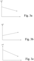
- the basic idea of the invention is that the spring is arranged and/or designed in such a way that the (restoring) force generated by it and acting against the drive direction decreases with increasing travel. In this way, it is possible for the (feeding) force generated in particular by a pneumatic drive and decreasing with increasing travel to be compensated by the spring in such a way that a cutting force generated when the knife is placed against a counter knife is at least is almost constant over long distances along the drive direction. The cutting force is therefore the same regardless of the distance between the standby position and the cutting position.
- the spring is arranged and/or designed in particular such that a course of the negative force characteristic corresponds to the course of a force characteristic generated by a particularly pneumatic drive of the adjusting device in the drive direction.
- the invention also makes it possible to reduce the width of a knife holder (i.e. in the drive direction), which in turn could increase the adjustment range while maintaining the same width.
- the arrangement (in particular a degree of inclination) and design of the spring (in particular the spring constant) is therefore selected in such a way that the force characteristic curve in the drive direction drops to the same extent as the characteristic curve of the force exerted by a (pneumatic) drive of the adjusting device, in particular having a diaphragm.
- the knife holder comprises in particular an attachment device with which the knife holder can be fastened, for example, to a crossbar of a cutting machine.
- the knife holder can comprise a lowering device with which the knife head can be moved in a lowering direction, in particular towards and away from a lower knife.
- the linear drive direction of the setting device is aligned orthogonally to the lowering direction.
- the knife can be set in a straight line in its axial direction against a cutting edge of a lower knife.
- the invention therefore preferably relates to such an adjusting device with which a circular knife can be fed in the axial direction of the circular knife onto a cutting edge of a lower knife.
- the invention also relates in particular to a cutting machine with a cross member to which at least one, preferably several, knife holders according to the invention are fastened.
- the spring also acts with a force component obliquely and in particular orthogonally to the straight drive direction.
- the spring does not act exclusively parallel to the drive direction during a driven adjustment process, but generates a force component both against the drive direction and obliquely to the drive direction.
- a torque acting on the knife head can be at least partially compensated, which is generated by the knife being pressed against a lower knife in the cutting position.
- the spring is arranged and designed in such a way that it counteracts a torque that is generated in the cutting position by pressing the circular knife against a counter knife in the drive direction. By compensating for this torque, also known as the tilting moment, the friction during the cutting process is reduced.
- the spring is in particular a helical spring.
- a helical spring has a spring wire that is wound/coiled in a helical shape.
- the wound spring wire defines a helical axis.
- this axis defined by the bound spring wire is straight.
- it can It can also be intended that the axis is curved. In this case, we speak of arc springs.
- the particularly straight screw axis is aligned at an angle to the drive direction.
- a force applied to the spring by the adjusting device acts transversely to the screw axis of the spring.
- the restoring force applied by the coil spring parallel to the drive direction has a negative force characteristic in particular.
- the coil spring is therefore aligned in such a way that a force generated by the drive of the adjusting device, which decreases with increasing adjustment travel, is compensated by a restoring force that decreases with increasing adjustment travel.
- a torque generated by pressing the circular blade onto a lower blade is compensated by a force acting through the coil spring in the screw axis.
- a longitudinal axis of the (helical) spring in the ready position is aligned at an angle of 30° to 80°, preferably 45° to 75°, particularly preferably 60° to 70° to the drive direction.
- the adjusting device comprises in particular a preferably pneumatic drive to drive the knife in a drive direction between the ready position and the cutting position.
- the adjusting device is designed such that the knife is driven by the drive from the ready position into the cutting position, while the spring is arranged to return to the ready position.
- the adjusting device has an adjusting piston device that can be pressurized in particular by means of compressed air, wherein the spring acts on the adjusting piston device on the side facing away from the pressurizable side.
- the adjusting piston device comprises at least one, preferably two membrane(s).
- a pressurized fluid in particular compressed air
- compressed air By using two membranes, an airtight space for the introduction of compressed air can be provided in a simple manner.
- the two membranes In order for the adjusting device to be driven by the introduction of compressed air, the two membranes have different effective areas. When compressed air is introduced between the membranes, the adjusting device is moved in the direction of the membrane with the larger effective area.
- the adjusting piston device has a multi-part adjusting piston head and at least one membrane, preferably both membranes, are fixed by the parts of the adjusting piston head. In this way, simple assembly of the adjusting piston device is possible.
- the adjusting piston device has an adjusting piston rod designed as an axis, wherein the axis is mounted at least axially movable by means of a bearing, so that the axis can be moved in the axial direction between the ready position and the cutting position by the drive of the adjusting device.
- a holder for a circular knife is coupled to the axle, whereby the holder is rotatably mounted to the axle.
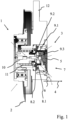
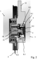
- the knife holder shown comprises a knife head 1 with a rotatably mounted holder for a circular knife 2.
- the knife holder also comprises a lowering device 12, only indicated schematically, with which the knife head 1 can be lowered downwards in the vertical direction in the figures.
- the knife holder also comprises an adjustment device 3 with which the circular knife 2 can be adjusted in a drive direction 4 which is orthogonal to the lowering direction, for example to a lower knife.
- the adjusting device 3 comprises an adjusting piston device 7.
- the adjusting piston device 7 comprises a multi-part adjusting piston head with a first adjusting piston head part 9.1, a second adjusting piston head part 9.2 and a screw 9.3, via which the adjusting piston head is connected to an axis 10.
- the axis 10 is mounted by means of a bearing 11 so that it can be moved in a straight line in the drive direction 4.
- the adjusting piston device 7 also comprises two membranes 8.1 and 8.2. The first membrane 8.1 is clamped between the first adjusting piston head part 9.1 and the second adjusting piston head part 9.2, while the second membrane 8.2 is clamped between the second adjusting piston head part 9.2 and the axis 10.
- compressed air can be introduced between the two membranes 8.1 and 8.2. Since the membranes 8.1 and 8.2 have a different size of effective surface, the introduction of compressed air moves the adjusting piston device 7.1 and thus also the circular blade 2 in the direction of the drive direction 4.
- a spring 5 designed as a helical spring is provided, the spring axis of which is arranged at an angle 6 obliquely to the drive direction 4.
- the spring 5 acts on the adjusting piston device 7 with a force that is opposite to the drive direction 4. Since this force acts transversely to the longitudinal axis of the spring 5, the restoring force decreases as the adjustment path increases. This ensures that the total force acting on a lower blade is constant regardless of the position along the adjustment path.
Landscapes
- Life Sciences & Earth Sciences (AREA)
- Forests & Forestry (AREA)
- Engineering & Computer Science (AREA)
- Mechanical Engineering (AREA)
- Physics & Mathematics (AREA)
- Fluid Mechanics (AREA)
- Details Of Cutting Devices (AREA)
Claims (13)
- Porte-couteau pour machines à couper, avec- une tête porte-couteau (1) pour maintenir un couteau (2) et- un dispositif de réglage (3), sachant que le dispositif de réglage (3)caractérisé en ce que• peut être entraîné dans une direction d'entraînement (4) entre une position de maintien prêt à servir et une position de coupe et• comprend un ressort (5) avec lequel le dispositif de réglage (3) est sollicité à l'opposé de la direction d'entraînement (4),
le ressort (5) produit une ligne caractéristique de force négative dans la direction d'entraînement (4). - Porte-couteau selon la revendication 1, sachant que le ressort (5) est disposé et/ou constitué de telle manière que la ligne caractéristique de force négative correspond au profil d'une ligne caractéristique de force générée par un système d'entraînement du dispositif de réglage (4) dans la direction d'entraînement (4).
- Porte-couteau selon la revendication 1 ou 2, sachant que le ressort (5) agit également avec une composante de force de façon inclinée par rapport à la direction d'entraînement (4).
- Porte-couteau selon la revendication 3, sachant que le ressort (5) s'oppose à un couple produit sur un contre-couteau dans la position de coupe par pression du couteau (2).
- Porte-couteau selon l'une quelconque des revendications précédentes, sachant que le ressort (5) est un ressort hélicoïdal.
- Porte-couteau selon l'une quelconque des revendications précédentes, sachant que dans la position de maintien prête à servir, un axe longitudinal du ressort (5) est orienté dans un angle (6) de 30° à 80° par rapport à la direction d'entraînement (4).
- Porte-couteau selon l'une quelconque des revendications précédentes, sachant que le dispositif de réglage (3) comporte un système à piston de réglage pressurisé (7).
- Porte-couteau selon la revendication 1, sachant que le ressort (5) vient en prise sur le côté éloigné du côté pressurisé sur le système à piston de réglage (7).
- Porte-couteau selon la revendication 7 ou 8, caractérisé en ce que le système à piston de réglage (7) comprend deux membranes (8.1, 8.2) entre lesquelles peut être introduit un fluide pressurisé.
- Porte-couteau selon la revendication 9, caractérisé en ce que les deux membranes (8.1, 8.2) comportent une surface active de taille différente.
- Porte-couteau selon la revendication 9 ou 10, sachant que le système à piston de réglage (7) comporte une tête de piston de réglage (9.1, 9.2) en plusieurs parties et les membranes sont fixées par les pièces (9.1, 9.2) de la tête de piston de réglage.
- Porte-couteau selon l'une quelconque des revendications 7 à 11, sachant que le système à piston de réglage (7) comporte une tige de piston de réglage constituée sous la forme d'un axe (10) et l'axe (10) est logé au moins axialement mobile au moyen d'un palier (11).
- Porte-couteau selon l'une quelconque des revendications précédentes, sachant que le porte-couteau comprend un dispositif de descente (12) pour la tête porte-couteau (1).
Priority Applications (2)
| Application Number | Priority Date | Filing Date | Title |
|---|---|---|---|
| EP22166663.9A EP4257309B1 (fr) | 2022-04-05 | 2022-04-05 | Porte-couteau pour machines à couper |
| US18/295,886 US12617113B2 (en) | 2022-04-05 | 2023-04-05 | Knife holder for cutting machines |
Applications Claiming Priority (1)
| Application Number | Priority Date | Filing Date | Title |
|---|---|---|---|
| EP22166663.9A EP4257309B1 (fr) | 2022-04-05 | 2022-04-05 | Porte-couteau pour machines à couper |
Publications (3)
| Publication Number | Publication Date |
|---|---|
| EP4257309A1 EP4257309A1 (fr) | 2023-10-11 |
| EP4257309C0 EP4257309C0 (fr) | 2024-09-18 |
| EP4257309B1 true EP4257309B1 (fr) | 2024-09-18 |
Family
ID=81327003
Family Applications (1)
| Application Number | Title | Priority Date | Filing Date |
|---|---|---|---|
| EP22166663.9A Active EP4257309B1 (fr) | 2022-04-05 | 2022-04-05 | Porte-couteau pour machines à couper |
Country Status (2)
| Country | Link |
|---|---|
| US (1) | US12617113B2 (fr) |
| EP (1) | EP4257309B1 (fr) |
Families Citing this family (1)
| Publication number | Priority date | Publication date | Assignee | Title |
|---|---|---|---|---|
| EP4368357A1 (fr) * | 2022-11-08 | 2024-05-15 | Dienes Werke für Maschinenteile GmbH & Co. KG | Porte-lame pour machines à couper |
Family Cites Families (6)
| Publication number | Priority date | Publication date | Assignee | Title |
|---|---|---|---|---|
| DE19806444C1 (de) * | 1998-02-17 | 1999-07-08 | Dienes Werke | Messerhalter mit hubunabhängiger Schnittkraftregelung |
| DE10242291A1 (de) * | 2002-03-08 | 2003-09-18 | Bilstein Spezialfab Wilhelm | Messerhalter mit mechanischer Schnittkrafteinstellung |
| US20030188611A1 (en) * | 2002-04-04 | 2003-10-09 | Solberg Gary I. | Slitter Knife system |
| DE10260031B3 (de) | 2002-12-19 | 2004-08-26 | Dienes Werke für Maschinenteile GmbH & Co KG | Messerhalter mit hubabhängigem Federkraftausgleich |
| EP1974877A1 (fr) * | 2007-03-26 | 2008-10-01 | Espo S.R.L. | Ensemble de coupe pour machines de coupe de matériau en feuilles |
| JP6560714B2 (ja) * | 2017-06-26 | 2019-08-14 | Towa株式会社 | ブレード交換機構、切断装置およびブレード交換方法 |
-
2022
- 2022-04-05 EP EP22166663.9A patent/EP4257309B1/fr active Active
-
2023
- 2023-04-05 US US18/295,886 patent/US12617113B2/en active Active
Also Published As
| Publication number | Publication date |
|---|---|
| EP4257309C0 (fr) | 2024-09-18 |
| US20230311356A1 (en) | 2023-10-05 |
| EP4257309A1 (fr) | 2023-10-11 |
| US12617113B2 (en) | 2026-05-05 |
Similar Documents
| Publication | Publication Date | Title |
|---|---|---|
| DE69303690T2 (de) | Schneidvorrichtung | |
| DE2718766C3 (de) | Stempel-Abstreifer-Anordnung | |
| EP1849569B2 (fr) | Dispositif destiné à usiner des pièces à l'aide d'ultrasons et procédé de fonctionnement d'un tel dispositif | |
| EP0911125A1 (fr) | Dispositif de coupe à grande vitesse pour des bandes laminées | |
| DE69315337T2 (de) | Maschine zum schneiden von bogen aus einer papierbahn und zum gleichzeitigen schneiden eines querstreifens | |
| EP0263359B1 (fr) | Dispositif à coupe transversale | |
| DE2108064B2 (de) | Blechschere | |
| EP2481492B1 (fr) | Outil de pliage pour le pliage à forme libre de tôles | |
| EP4257309A1 (fr) | Porte-couteau pour machines à couper | |
| EP0523435A1 (fr) | Coupeuse transversale d'une plieuse pour des rotatives à bobines | |
| DE3218799C2 (de) | Vorrichtung zur Halterung des Obermessers einer Schwingschnitt-Tafelblechschere | |
| DE2453687A1 (de) | Lochvorrichtung | |
| DE4416522A1 (de) | Papierbahn-Schneideeinrichtung | |
| DE102010033191B4 (de) | Vorrichtung zum Schneiden von hochfesten Werkstücken | |
| DE3022772A1 (de) | Vorrichtung zum schneiden von prospekten, bedruckten blaettern o.dgl. gegenstaenden | |
| DE102007025967A1 (de) | Pendelführungseinrichtung für ein Hubbewegungen durchführendes Sägeblatt einer Hubsägemaschine | |
| DE10242291A1 (de) | Messerhalter mit mechanischer Schnittkrafteinstellung | |
| DE3615381C2 (de) | Fuehrungsvorrichtung fuer den messerbalken einer schere zur blechbearbeitung | |
| DE102018122005A1 (de) | Querschneideeinrichtung und Verfahren zur Stabilisierung einer Schnittkante beim Quetschschnitt | |
| DE102004038753B3 (de) | Vorrichtung zum Vereinzeln von Blättern eines Aufzeichnungsträgers | |
| AT390753B (de) | Fuehrung von flaechenmaterial in anlagen mit rundmessern | |
| EP0045714A1 (fr) | Dispositif pour rainer longitudinalement des bandes de papier | |
| DE102009029359B4 (de) | 10.09.2009Vorrichtung zur Bearbeitung von Stirnenden unrunder Rohre | |
| EP0416167B1 (fr) | Dispositif d'affûtage d'une hélice | |
| DE29717396U1 (de) | Messerhalter mit anstellbarem Kreismesser |
Legal Events
| Date | Code | Title | Description |
|---|---|---|---|
| PUAI | Public reference made under article 153(3) epc to a published international application that has entered the european phase |
Free format text: ORIGINAL CODE: 0009012 |
|
| STAA | Information on the status of an ep patent application or granted ep patent |
Free format text: STATUS: THE APPLICATION HAS BEEN PUBLISHED |
|
| AK | Designated contracting states |
Kind code of ref document: A1 Designated state(s): AL AT BE BG CH CY CZ DE DK EE ES FI FR GB GR HR HU IE IS IT LI LT LU LV MC MK MT NL NO PL PT RO RS SE SI SK SM TR |
|
| STAA | Information on the status of an ep patent application or granted ep patent |
Free format text: STATUS: REQUEST FOR EXAMINATION WAS MADE |
|
| 17P | Request for examination filed |
Effective date: 20231109 |
|
| RBV | Designated contracting states (corrected) |
Designated state(s): AL AT BE BG CH CY CZ DE DK EE ES FI FR GB GR HR HU IE IS IT LI LT LU LV MC MK MT NL NO PL PT RO RS SE SI SK SM TR |
|
| GRAP | Despatch of communication of intention to grant a patent |
Free format text: ORIGINAL CODE: EPIDOSNIGR1 |
|
| STAA | Information on the status of an ep patent application or granted ep patent |
Free format text: STATUS: GRANT OF PATENT IS INTENDED |
|
| RIC1 | Information provided on ipc code assigned before grant |
Ipc: B26D 7/26 20060101AFI20240319BHEP |
|
| INTG | Intention to grant announced |
Effective date: 20240417 |
|
| GRAS | Grant fee paid |
Free format text: ORIGINAL CODE: EPIDOSNIGR3 |
|
| GRAA | (expected) grant |
Free format text: ORIGINAL CODE: 0009210 |
|
| STAA | Information on the status of an ep patent application or granted ep patent |
Free format text: STATUS: THE PATENT HAS BEEN GRANTED |
|
| AK | Designated contracting states |
Kind code of ref document: B1 Designated state(s): AL AT BE BG CH CY CZ DE DK EE ES FI FR GB GR HR HU IE IS IT LI LT LU LV MC MK MT NL NO PL PT RO RS SE SI SK SM TR |
|
| REG | Reference to a national code |
Ref country code: GB Ref legal event code: FG4D Free format text: NOT ENGLISH |
|
| REG | Reference to a national code |
Ref country code: CH Ref legal event code: EP |
|
| REG | Reference to a national code |
Ref country code: IE Ref legal event code: FG4D Free format text: LANGUAGE OF EP DOCUMENT: GERMAN |
|
| REG | Reference to a national code |
Ref country code: DE Ref legal event code: R096 Ref document number: 502022001679 Country of ref document: DE |
|
| U01 | Request for unitary effect filed |
Effective date: 20241011 |
|
| U07 | Unitary effect registered |
Designated state(s): AT BE BG DE DK EE FI FR IT LT LU LV MT NL PT RO SE SI Effective date: 20241031 |
|
| PG25 | Lapsed in a contracting state [announced via postgrant information from national office to epo] |
Ref country code: NO Free format text: LAPSE BECAUSE OF FAILURE TO SUBMIT A TRANSLATION OF THE DESCRIPTION OR TO PAY THE FEE WITHIN THE PRESCRIBED TIME-LIMIT Effective date: 20241218 |
|
| PG25 | Lapsed in a contracting state [announced via postgrant information from national office to epo] |
Ref country code: GR Free format text: LAPSE BECAUSE OF FAILURE TO SUBMIT A TRANSLATION OF THE DESCRIPTION OR TO PAY THE FEE WITHIN THE PRESCRIBED TIME-LIMIT Effective date: 20241219 |
|
| PG25 | Lapsed in a contracting state [announced via postgrant information from national office to epo] |
Ref country code: HR Free format text: LAPSE BECAUSE OF FAILURE TO SUBMIT A TRANSLATION OF THE DESCRIPTION OR TO PAY THE FEE WITHIN THE PRESCRIBED TIME-LIMIT Effective date: 20240918 |
|
| PG25 | Lapsed in a contracting state [announced via postgrant information from national office to epo] |
Ref country code: RS Free format text: LAPSE BECAUSE OF FAILURE TO SUBMIT A TRANSLATION OF THE DESCRIPTION OR TO PAY THE FEE WITHIN THE PRESCRIBED TIME-LIMIT Effective date: 20241218 |
|
| PG25 | Lapsed in a contracting state [announced via postgrant information from national office to epo] |
Ref country code: RS Free format text: LAPSE BECAUSE OF FAILURE TO SUBMIT A TRANSLATION OF THE DESCRIPTION OR TO PAY THE FEE WITHIN THE PRESCRIBED TIME-LIMIT Effective date: 20241218 Ref country code: NO Free format text: LAPSE BECAUSE OF FAILURE TO SUBMIT A TRANSLATION OF THE DESCRIPTION OR TO PAY THE FEE WITHIN THE PRESCRIBED TIME-LIMIT Effective date: 20241218 Ref country code: HR Free format text: LAPSE BECAUSE OF FAILURE TO SUBMIT A TRANSLATION OF THE DESCRIPTION OR TO PAY THE FEE WITHIN THE PRESCRIBED TIME-LIMIT Effective date: 20240918 Ref country code: GR Free format text: LAPSE BECAUSE OF FAILURE TO SUBMIT A TRANSLATION OF THE DESCRIPTION OR TO PAY THE FEE WITHIN THE PRESCRIBED TIME-LIMIT Effective date: 20241219 |
|
| PG25 | Lapsed in a contracting state [announced via postgrant information from national office to epo] |
Ref country code: IS Free format text: LAPSE BECAUSE OF FAILURE TO SUBMIT A TRANSLATION OF THE DESCRIPTION OR TO PAY THE FEE WITHIN THE PRESCRIBED TIME-LIMIT Effective date: 20250118 |
|
| PG25 | Lapsed in a contracting state [announced via postgrant information from national office to epo] |
Ref country code: SM Free format text: LAPSE BECAUSE OF FAILURE TO SUBMIT A TRANSLATION OF THE DESCRIPTION OR TO PAY THE FEE WITHIN THE PRESCRIBED TIME-LIMIT Effective date: 20240918 |
|
| PG25 | Lapsed in a contracting state [announced via postgrant information from national office to epo] |
Ref country code: ES Free format text: LAPSE BECAUSE OF FAILURE TO SUBMIT A TRANSLATION OF THE DESCRIPTION OR TO PAY THE FEE WITHIN THE PRESCRIBED TIME-LIMIT Effective date: 20240918 |
|
| PG25 | Lapsed in a contracting state [announced via postgrant information from national office to epo] |
Ref country code: CZ Free format text: LAPSE BECAUSE OF FAILURE TO SUBMIT A TRANSLATION OF THE DESCRIPTION OR TO PAY THE FEE WITHIN THE PRESCRIBED TIME-LIMIT Effective date: 20240918 Ref country code: PL Free format text: LAPSE BECAUSE OF FAILURE TO SUBMIT A TRANSLATION OF THE DESCRIPTION OR TO PAY THE FEE WITHIN THE PRESCRIBED TIME-LIMIT Effective date: 20240918 |
|
| PG25 | Lapsed in a contracting state [announced via postgrant information from national office to epo] |
Ref country code: SK Free format text: LAPSE BECAUSE OF FAILURE TO SUBMIT A TRANSLATION OF THE DESCRIPTION OR TO PAY THE FEE WITHIN THE PRESCRIBED TIME-LIMIT Effective date: 20240918 |
|
| U20 | Renewal fee for the european patent with unitary effect paid |
Year of fee payment: 4 Effective date: 20250325 |
|
| PLBE | No opposition filed within time limit |
Free format text: ORIGINAL CODE: 0009261 |
|
| STAA | Information on the status of an ep patent application or granted ep patent |
Free format text: STATUS: NO OPPOSITION FILED WITHIN TIME LIMIT |
|
| 26N | No opposition filed |
Effective date: 20250619 |
|
| REG | Reference to a national code |
Ref country code: CH Ref legal event code: H13 Free format text: ST27 STATUS EVENT CODE: U-0-0-H10-H13 (AS PROVIDED BY THE NATIONAL OFFICE) Effective date: 20251125 |
|
| PG25 | Lapsed in a contracting state [announced via postgrant information from national office to epo] |
Ref country code: MC Free format text: LAPSE BECAUSE OF FAILURE TO SUBMIT A TRANSLATION OF THE DESCRIPTION OR TO PAY THE FEE WITHIN THE PRESCRIBED TIME-LIMIT Effective date: 20240918 |
|
| PG25 | Lapsed in a contracting state [announced via postgrant information from national office to epo] |
Ref country code: CH Free format text: LAPSE BECAUSE OF NON-PAYMENT OF DUE FEES Effective date: 20250430 |
|
| U1N | Appointed representative for the unitary patent procedure changed after the registration of the unitary effect |
Representative=s name: FEUCKER, MAX MARTIN; DE |
|
| PG25 | Lapsed in a contracting state [announced via postgrant information from national office to epo] |
Ref country code: IE Free format text: LAPSE BECAUSE OF NON-PAYMENT OF DUE FEES Effective date: 20250405 |
|
| U20 | Renewal fee for the european patent with unitary effect paid |
Year of fee payment: 5 Effective date: 20260318 |
|
| PG25 | Lapsed in a contracting state [announced via postgrant information from national office to epo] |
Ref country code: CY Free format text: LAPSE BECAUSE OF FAILURE TO SUBMIT A TRANSLATION OF THE DESCRIPTION OR TO PAY THE FEE WITHIN THE PRESCRIBED TIME-LIMIT Effective date: 20240918 |