EP4257313A2 - Installation de division de plaques pour diviser des pièces en forme de plaque et procédé pour faire fonctionner celle-ci - Google Patents
Installation de division de plaques pour diviser des pièces en forme de plaque et procédé pour faire fonctionner celle-ci Download PDFInfo
- Publication number
- EP4257313A2 EP4257313A2 EP23194934.8A EP23194934A EP4257313A2 EP 4257313 A2 EP4257313 A2 EP 4257313A2 EP 23194934 A EP23194934 A EP 23194934A EP 4257313 A2 EP4257313 A2 EP 4257313A2
- Authority
- EP
- European Patent Office
- Prior art keywords
- workpiece
- feed table
- segment
- dividing
- conveying direction
- Prior art date
- Legal status (The legal status is an assumption and is not a legal conclusion. Google has not performed a legal analysis and makes no representation as to the accuracy of the status listed.)
- Pending
Links
- 238000000034 method Methods 0.000 title claims abstract description 34
- 239000000872 buffer Substances 0.000 claims abstract description 78
- 230000003139 buffering effect Effects 0.000 claims abstract description 8
- 238000012546 transfer Methods 0.000 description 9
- 238000013461 design Methods 0.000 description 3
- 238000012545 processing Methods 0.000 description 3
- 238000010276 construction Methods 0.000 description 2
- 208000027418 Wounds and injury Diseases 0.000 description 1
- 238000010073 coating (rubber) Methods 0.000 description 1
- 230000006378 damage Effects 0.000 description 1
- 208000014674 injury Diseases 0.000 description 1
- 239000012464 large buffer Substances 0.000 description 1
- 238000012423 maintenance Methods 0.000 description 1
Images


Classifications
-
- B—PERFORMING OPERATIONS; TRANSPORTING
- B27—WORKING OR PRESERVING WOOD OR SIMILAR MATERIAL; NAILING OR STAPLING MACHINES IN GENERAL
- B27B—SAWS FOR WOOD OR SIMILAR MATERIAL; COMPONENTS OR ACCESSORIES THEREFOR
- B27B5/00—Sawing machines working with circular or cylindrical saw blades; Components or equipment therefor
- B27B5/02—Sawing machines working with circular or cylindrical saw blades; Components or equipment therefor characterised by a special purpose only
- B27B5/06—Sawing machines working with circular or cylindrical saw blades; Components or equipment therefor characterised by a special purpose only for dividing plates in parts of determined size, e.g. panels
- B27B5/065—Sawing machines working with circular or cylindrical saw blades; Components or equipment therefor characterised by a special purpose only for dividing plates in parts of determined size, e.g. panels with feedable saw blades, e.g. arranged on a carriage
-
- B—PERFORMING OPERATIONS; TRANSPORTING
- B27—WORKING OR PRESERVING WOOD OR SIMILAR MATERIAL; NAILING OR STAPLING MACHINES IN GENERAL
- B27B—SAWS FOR WOOD OR SIMILAR MATERIAL; COMPONENTS OR ACCESSORIES THEREFOR
- B27B31/00—Arrangements for conveying, loading, turning, adjusting, or discharging the log or timber, specially designed for saw mills or sawing machines
- B27B31/04—Turning equipment
-
- B—PERFORMING OPERATIONS; TRANSPORTING
- B27—WORKING OR PRESERVING WOOD OR SIMILAR MATERIAL; NAILING OR STAPLING MACHINES IN GENERAL
- B27M—WORKING OF WOOD NOT PROVIDED FOR IN SUBCLASSES B27B - B27L; MANUFACTURE OF SPECIFIC WOODEN ARTICLES
- B27M1/00—Working of wood not provided for in subclasses B27B - B27L, e.g. by stretching
- B27M1/08—Working of wood not provided for in subclasses B27B - B27L, e.g. by stretching by multi-step processes
Definitions
- the present invention relates to a panel dividing system for dividing plate-shaped workpieces according to the preamble of claim 1, and a method for operating such a panel dividing system according to the preamble of the independent claim.
- Such panel dividing systems are available both from the market and from the DE 10 2008 034 050 A1 , the DE 10 2009 038 120 A1 or the EP 2 422 944 A1 known. These panel dividing systems are used to divide large-format panel-shaped workpieces, such as those used in the furniture industry. When operating such panel dividing systems, the divided workpieces must be handled after a processing step, for example in order to send them for stacking or a new processing step. This requires either at least one operator to handle the divided workpieces, or the workpieces are handled by machine support. In the first-mentioned variant, the personnel effort, the resulting burden on the operator and the possible risk of injury are high, whereas with machine-assisted handling there is a risk of high design and construction effort. This entails corresponding acquisition costs and high maintenance costs.
- the DE 38 40 325 A1 discloses a panel dividing system in which a section of a panel to be divided lies on a side support table during the sawing process. The loose section after the sawing process can then be conveyed back to the feed table.
- the DE 39 11 639 A1 describes a panel dividing system with a vertically movable buffer.
- the present invention is therefore based on the object of enabling a fully automatic use of a panel dividing system with simple structural means.
- the panel dividing system according to the invention has the advantage that it can work fully automatically, which means that a very high level of economic efficiency can be achieved.
- the panel dividing system is inexpensive and constructed using simple structural means.
- a workpiece can be transported to a dividing device by means of a conveyor and can be comminuted there into a divided workpiece.
- the divided workpiece can be buffered in a buffer device before a further division process.
- the buffer device is designed such that the buffered workpiece can be moved in a second conveying direction, the second conveying direction being oriented transversely to the first conveying direction.
- the buffer device is not just a storage option, but rather an active device that can move the buffered workpiece in a targeted manner. The buffer device can thus move the workpiece in the second conveying direction towards the feed table or away from the feed table.
- the expression “across the first conveying direction” is to be understood in the broadest sense.
- the second conveying direction can thus be oriented obliquely, i.e. at an angle that deviates from the orthogonal, or orthogonally to the first conveying direction.
- the buffer device can have at least one further conveyor device for moving the buffered workpiece in the second conveying direction.
- the buffer device can have two conveyor devices for moving the buffered workpiece. This means that smaller conveyor devices can be used, whereby only the conveyor on which the workpiece is located has to be driven to transport the buffered workpiece. If several workpieces are buffered in the buffer device, the separate conveyor devices can be used to handle the workpieces simultaneously but differently.
- the buffer device can have a first segment, which is arranged laterally from the feed table, and a separate second segment, which is arranged in the area of the feed table, the first segment having a first of the further conveying devices and the second segment having a second of the further ones Funding facilities are assigned.
- the first segment and the first additional conveyor device can therefore be used to buffer and shift workpieces in the second conveying direction. Buffer space can thus be released in a section of the first segment as required, for example in an area of the first segment adjacent to the feed table, or a workpiece can be brought specifically to the feed table.
- the capacity of the buffer ie the number of storage spaces for workpieces, is increased, and the order of the workpieces can be changed in the direction of the feed table .
- the buffered workpiece is transferred to the feed table and, if necessary, the workpiece is positioned.
- the first segment can also be referred to as the “active workpiece buffer” or “active strip buffer”.
- the second segment can also be referred to as “lateral handover”.
- the panel dividing system can have a handling device for handling possibly divided workpieces, for example a robot with a suction gripping device.
- a handling device for handling possibly divided workpieces for example a robot with a suction gripping device.
- This can be arranged on a projecting end of a robot arm of the robot and can be used to pick up or grip workpieces.
- a divided workpiece can be picked up after a dividing process and placed on the buffer device.
- the divided workpiece can be rotated if necessary.
- the working area or storage area of the handling device or the robot and the buffer device, in particular the first segment of the buffer device at least partially overlap.
- an area of the first segment of the buffer device that is adjacent to the feed table is in the working area of the handling device, whereas an area of the first segment that is remote from the feed table is not.
- An upper side of the first segment or the first further conveyor device can expediently be elevated at least temporarily relative to an upper side of the feed table. This makes the transfer from the first segment to the feed table easier. It is conceivable that the top of the first further conveyor device or the first segment is increased by 5 to 35 millimeters, more preferably by 10 to 30 millimeters, more preferably by 15 to 25 millimeters, more preferably by 20 millimeters.
- the second segment or the second of the further conveying devices can be designed to be height-adjustable relative to the feed table, or the feed table can be height-adjustable relative to the second segment.
- the second segment or the second further conveyor device can move between a first position in which an upper side of the second segment or the second further conveying device is arranged below a top side of the feed table, and a second position in which the top of the second segment or the second further conveying device is arranged above the top of the feed table (and preferably at the same height as the first segment).
- This also applies to the kinematically opposite case, in which the feed table is height-adjustable relative to the second segment.
- the second segment or the second further conveyor device can be activated in a very targeted manner when a buffered workpiece is transferred from the first segment to the second segment. This makes handover easier. If no transfer takes place, the second segment or the second additional conveyor device can remain in its first, recessed position (or the feed table can remain in its elevated position), so that workpieces can be fed undisturbed in the first conveying direction by the first conveyor device can be done.
- the first further conveyor device and/or the second further conveyor device can each have a rotating conveyor element. This enables gentle transport of the workpieces, since there is no relative movement in the contact plane between the workpiece and the conveying element.
- the rotating conveyor element can be a belt or a chain.
- roller rails can also be used as a conveying element, whereby a slider can drive the workpieces, or where the rollers themselves are driven.
- the rollers of the roller rails can have an elastic surface, for example in the form of a rubber coating.
- a displaceable stop can be arranged on the feed table for aligning the workpiece that is initially buffered and then conveyed to the feed table by the buffer device. This makes it possible to create a defined stop for a workpiece without impairing the handling and transport of the workpieces due to a fixed stop. It is advantageous if the stop is displaced between a first position, in which the stop is located below an upper side of the feed table, and between a second position, in which the stop is arranged at least partially above the upper side of the feed table can be.
- the stop can be displaced in various ways, for example the stop can be designed to be pivotable, extendable or telescopic. It is not necessary for the stop to form a single, continuous stop surface. Rather, for the stop to function, it is also sufficient that several stop sections, for example in the form of pins, are displaced relative to the surface of the feed table.
- the second segment can have a driver element coupled to the second further conveyor device, with which the divided workpiece can be moved to align it with the stop.
- the driver element can be coupled to the conveying element of the second further conveying device.
- the driver element can have a contact section which is displaceable in such a way that it is arranged in a first position below a top side of a feed table and in a second position at least partially above the top side of the feed table.
- the driver element has an actuator which, when activated, displaces the contact section in such a way that it is arranged at least in some areas above the top of the feed table.
- the actuator it is conceivable that it is designed as a pneumatic cylinder or hydraulic cylinder.
- the divided workpiece can expediently be handled by means of a handling device, for example by means of a robot with a suction gripping device. This can be arranged on a projecting end of a robot arm of the robot. Using the handling device or the robot, a divided workpiece can be picked up after a division process and placed on the buffer device. The divided workpiece can be rotated.
- a handling device for example by means of a robot with a suction gripping device. This can be arranged on a projecting end of a robot arm of the robot.
- a divided workpiece can be picked up after a division process and placed on the buffer device.
- the divided workpiece can be rotated.
- the working area or storage area of the handling device or the robot and the buffer device, in particular the first segment of the buffer device at least partially overlap. In particular, an area of the first segment of the buffer device that is adjacent to the feed table is in the working area of the handling device, whereas an area of the first segment that is remote from the feed table is not.
- the divided workpiece can be transferred from a first segment of the buffer device, which is arranged laterally to the feed table and buffers the divided workpiece, to a separate second segment of the buffer device, which is arranged in the area of the feed table.
- the actual buffering of workpieces can therefore take place in a first segment of the buffer device outside the feed table.
- the first segment can also be referred to as the “active workpiece buffer” or “active strip buffer”.
- the transfer and, if necessary, positioning of the second workpiece onto the feed table can be done with the help of the second segment, which is arranged in the area of the feed table.
- the second segment can also be referred to as “lateral handover”.
- the second segment can expediently be raised relative to the feed table to at least the height of the first segment before or during the transfer of the divided workpiece and its height can thus be adjusted to the first segment.
- the second segment can thus be raised in a very targeted manner when a workpiece is transferred from the first segment to the second segment. If no such transfer takes place, the second segment can remain in a lowered position in which an upper side of the second segment is arranged below an upper side of the feed table. This means that workpieces can be conveyed undisturbed in the first conveying direction of the feed table.
- the divided workpiece can be moved on the first segment by means of a first further conveyor device and can be moved on the second segment by means of a second further conveyor device, wherein preferably the second further conveyor device is only activated as soon as a section of the divided workpiece second segment reached.
- the second further conveyor device is only activated as soon as a section of the divided workpiece second segment reached.
- rotating operation of the second further conveyor device can be avoided, so that positioning tasks can also be carried out by the second further conveyor device, for example.
- the divided workpiece can be placed on the feed table by lowering the second segment. This allows the workpiece to be placed gently on the feed table.
- the divided workpiece placed on the feed table can be moved to a displaceable stop of the feed table and pressed against it for alignment relative to the feed table and / or the dividing device by means of a driver element arranged at least in some areas above an upper side of the feed table.
- the stop can be displaceably arranged on the feed table.
- the stop can be displaced in various ways, for example the stop can be pivoted, extended or telescoped.
- the driver element can be coupled to the second further conveyor device, in particular with a rotating conveyor element of the second further conveyor device. This means that the workpiece can be transported using the second segment and positioned relative to the feed table. The expenditure on equipment is therefore significantly reduced.
- the divided workpiece lying on the feed table can first be fixed in the aligned state by at least one clamping element, and then the driver element and the stop can be displaced away from the divided workpiece.
- the driver element presses the workpiece against the stop so that the workpiece is in a clamped state.
- a clamping element fixes the workpiece so that the clamped position is maintained.
- the clamping element is connected, for example, by means of a program slide and can feed the divided workpiece to a further dividing process.
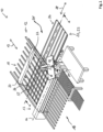
- a panel dividing system has the overall reference number 10. It includes a feed table 12 formed from several roller rails, a dividing device 13, in the present case designed as a saw, with a dividing line 14 ("saw line"), and a removal table 16.
- the removal table 16 can consist of several roller rails or as a segmented air cushion table be educated. Alternatively, the removal table 16 can have other transport elements, for example driven or non-driven belts or rollers.
- the division line 14 is in Figure 1 not immediately recognizable and therefore only indicated as a dash-dotted line.
- the plate dividing system 10 also includes a first conveyor device 18, which in the present case comprises a portal-like program slide 20 which is movably held on side rails (without reference numbers) and to which a plurality of collets 22 are attached. For reasons of clarity, only one collet chuck 22 is provided with a reference number.
- a workpiece lying on the feed table 12 can be moved in the direction of the dividing line 14 along a first conveying direction 19 indicated by a double arrow.
- the plate dividing system 10 further comprises a handling device 23, in the present case a robot 24.
- This comprises a base 26 and a robot arm 28 which is articulated to the base 26 and can be rotated about a vertical axis 27 relative to the base 26.
- the robot arm 28 in turn comprises two relative to one another a horizontal axis (without reference numerals) pivotable sections and a plate-shaped suction gripping device 30 attached to the projecting end of the robot arm and arranged in a substantially horizontal plane.
- the suction gripping device 30 is also relative to the robot arm 28 about a vertical axis (without reference numerals) rotatably mounted.
- the robot 24 shown in the present embodiment is a multi-axis robot with a relatively simple design. In principle, it is of course also conceivable to use another robot that has several movement and pivot axes. However, fully automatic operation of the panel dividing system 10 can also be achieved with the robot 24 shown here.
- the suction gripping device 30 is designed as a plate-shaped truss construction and has a large number of individual pneumatic suction cups 29 on its underside. This can be used to create workpieces Different sizes, for example workpieces that are smaller than the total extent of the suction gripping device 30, can be gripped without any problems.
- the plate dividing system 10 also has a buffer device 31 with a buffer table 32.
- the buffer table 32 is arranged laterally from the feed table 12 as seen in the first conveying direction 19 and can also be referred to as the first segment 33 of the buffer device 31.
- a buffered workpiece can be moved in a second conveying direction 38.
- the second conveying direction 38 is oriented transversely to the first conveying direction 19, in the present case orthogonally. In embodiments not shown, a different angle between the two conveying directions 19, 38 is also conceivable.
- the buffer device 31 extends into the feed table 12 and has a second segment 35.
- the second segment 35 is arranged in the feed table 12.
- the robot 24 has a working area or storage area which is circular in the top view and in the plane of the feed table 12, removal table 16 and buffer device 31, the center of which forms the axis 27.
- This working area overlaps with the buffer device 31, in particular with the first segment 33 of the buffer device 31, and there in turn with an area 37 adjacent to the feed table 12.
- a divided workpiece can thus be picked up after a dividing process, if necessary rotated and placed on the buffer device 31. in particular on the first segment 33 of the buffer device 31.
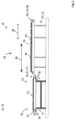
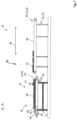
- Figure 2 shows a schematic and partially sectioned view of the panel dividing system 10 along section AA in Figure 1 , i.e. the area of the buffer device 31 and the feed table 12.
- a first further conveyor device 34 is assigned to the first segment 33 and a second further conveyor device 36 is assigned to the second segment 35.
- the first further conveyor device 34 and the second further conveyor device 36 each have a plurality of parallel rotating conveyor elements 40, 42 in the form of belt conveyors 44, 46.
- other conveying elements for example in the form of a chain or in the form of rollers with a slide for moving the workpieces, are also conceivable.
- a top side 50 of the first segment 33 or the first further conveyor device 34 is elevated compared to a top side 52 of the feed table 12.
- the increase can be between 10 and 30 millimeters, for example 20 millimeters. Other distances are also conceivable.
- the second segment 35 or the second conveyor device 36 is designed to be height-adjustable relative to the feed table 12.
- the second segment 35 or the second further conveyor device 36 can be moved between a first position, in which an upper side 54 of the second segment 35 or the second further conveyor device 36 is arranged below the upper side 52 of the feed table 12, and a second position, in which the top 54 of the second segment 35 is arranged above the top 52 of the feed table.
- a workpiece lying on the feed table 12 can be transported from the first conveyor device 18 along the first conveying direction 19, for example Divider 13 can be moved without this movement being hindered by the buffer device 31 and the second segment 35.
- the feed table is designed to be height-adjustable relative to the second segment of the buffer device.
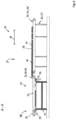
- FIG 3 an operating situation is shown in which the second segment 35 or the second further conveyor device 36 is in the second position, in which the top 54 of the second segment 35 is arranged above the top 52 of the feed table.
- a workpiece 48 can be transferred from the first segment 33 to the second segment 35.
- the first further conveyor device 34 with the belt conveyor 46 is first activated, so that the workpiece 48 is moved in the second conveying direction 38 towards the feed table 12.
- this is also activated.
- a vertically displaceable stop 56 for aligning the workpiece 48 is arranged on the feed table 12. If the singular is used here and below for the stop 56, this does not mean that it necessarily has to be a single element.
- the purpose of the stop 56 is to define a stop line orthogonal to the dividing line 14, as will be explained in more detail below. For this purpose, several individual stops can be provided, which are arranged in a straight line orthogonal to the dividing line 14, or an elongated straight "angle ruler" orthogonal to the dividing line 14 can be provided.
- the second segment 35 has a driver element 58, which is connected to the second further conveyor device 36 or to the rotating one Conveying element 40 (belt conveyor 44) is coupled and with which the workpiece 48 can be moved to the stop 56.
- the singular used does not mean that only a single driver element 58 is necessarily provided.
- the purpose of the driver element 58 is to move a workpiece lying on the feed table 12 translationally and transversely to the first conveying direction 19.
- several driver elements 58 should generally be used, for example one driver element 58 on each of the parallel belt conveyors 44, in order to avoid twisting of the workpiece 48 during movement.
- the driver element 58 is attached to the rotating conveyor element 40 or the belt conveyor 44, so that it cannot carry out a completely rotating movement.
- a driver element that can be coupled to the rotating conveyor element 40 in the form of the belt conveyor 44 is also conceivable.
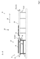
- the second additional conveyor device 36 of the second segment 35 is also deactivated.
- the second segment 35 or the second further conveyor device 36 is lowered, for example by means of a pneumatic or electric actuator, so that the workpiece 48 comes to rest on the top 52 of the feed table 12.
- the displaceable stop 56 is again shifted upwards, for example by means of a pneumatic or electrical actuator, into a position in which it is arranged at least in some areas above the top 52 of the feed table 12.
- the second conveyor 36 is further moved so that the driver element 58 in Figure 6 is in the extreme left position, and then the driver element 58 is moved upwardly into its extended position in which it protrudes with its contact portion 60 above the top 52 of the feed table 12.
- the second further conveyor device 36 of the second segment 35 which is no longer in contact with the workpiece 48 lying on the feed table 12 due to the lowering, is then driven, so that the driver element 58 moves to the side of the second segment 35 or .of the feed table 12, in Figure 6 i.e. moved all the way to the left.
- the driver element 58 is then shifted upwards in such a way that a contact section 60 is moved from a first position below the top 52 of the feed table 12 to a second position in which the contact section 60 is arranged at least partially above the top 52 of the feed table 12.
- the driver element 58 has an actuator in the form of a pneumatic cylinder (not shown). In embodiments not shown, actuators in the form of a hydraulic cylinder or an electric servomotor are also conceivable.
- the stop 56 and the alignment process just described define a position of the workpiece 48 that is orthogonal to the saw line 14.
- the workpiece 48 is thus aligned relative to the saw line 14.
- the workpiece 48 thus maintains its fixed position aligned with the saw line 14.
- Now at least the driver 58 is connected to the contact section 60 and possibly also the stop 56 again lowered.
- the stop 56 and the driver element 58 are, as indicated above, moved into a position below the top 52 of the feed table 12 and thus moved away from the workpiece 48.
- the second further conveyor device 36 in the form of the belt conveyor 44 is moved in such a way that the driver element 58, the contact section 60 of which is (still) below the top 52 of the feed table 12 is located, on the side of the feed table 12 facing away from the stop 56 (i.e. in the Figures 2 and the extreme left position shown). In this way, when the further workpiece 49 is transferred to the second segment 35, the maximum conveying path of the second belt conveyor 46 is available.
- workpieces 48, 49 can be temporarily stored ("buffered"), so that other workpieces lie on the feed table 12 and can be fed to the dividing device 13.
- the first belt conveyor 46 of the first segment 34 it is also possible for the first belt conveyor 46 of the first segment 34 to also move a workpiece lying on it away from the feed table 12, so that the robot 24 can move a divided workpiece between the feed table 12 and a workpiece already lying in the buffer device 31 can place the workpiece.
- a plate dividing system 10 for dividing plate-shaped workpieces 48, 49 is provided with a feed table 12, a conveyor device 18 for transporting an initial workpiece on the feed table 12 in a first conveying direction 19, one arranged after the feed table 12 as seen in the first conveying direction 19
- the plate dividing system 10 is characterized in that the buffer device 31 has at least one further conveyor device 34, 36, preferably two conveyor devices 34, 36, for moving the buffered workpiece 48 in the second conveying direction 38.
- the plate dividing system 10 is characterized in that the buffer device 31 has a first segment 33, which is arranged laterally from the feed table 12, and a separate second segment 35, which is arranged in the area of the feed table 12, wherein the first segment 33 is assigned a first of the further conveying devices 34 and the second segment 35 is assigned a second of the further conveying devices 36.
- the plate dividing system 10 is characterized in that an upper side 50 of the first segment 33 or the first further conveyor device 34 is at least temporarily elevated relative to an upper side 52 of the feed table 12.
- the plate dividing system 10 according to one of the two previous aspects is characterized in that the second segment 35 or the second further conveyor device 36 is designed to be height-adjustable relative to the feed table 12 or the feed table is designed to be height-adjustable relative to the second segment.
- the plate dividing system 10 is characterized in that the first further conveyor device 34 and/or the second further conveyor device 36 each have/have a rotating conveyor element 40, 42.
- the plate dividing system 10 is characterized in that a displaceable stop 56 for aligning the buffered workpiece 48 is arranged on the feed table 12.
- the plate dividing system 10 according to one of the previous five aspects is characterized in that the second segment 35 has a driver element 58 coupled to the second further conveyor device 36, in particular to its conveyor element 40, 44, with which the divided workpiece 48 is aligned can be moved to the stop 56.
- the plate dividing system 10 is characterized in that the driver element 58 has a contact section 60 which is displaceable in such a way that it is in a first position below a top side 52 of the feed table 12 and in a second position at least partially above the Top 52 of the feed table 12 is arranged.
- the method according to the previous aspect is characterized in that the divided workpiece 48, 49 is transferred from a first segment 33 of the buffer device 31, which is arranged laterally to the feed table 12 and buffers the divided workpiece 48, 49, to a separate second segment 35 is transferred to the buffer device 31, which is arranged in the area of the feed table 12.
- the method according to the previous aspect is characterized in that the second segment 35 is raised relative to the feed table 12 at least approximately to the level of the first segment 33 before or during the transfer of the divided workpiece 48, 49 or that the feed table before or is lowered relative to the second segment during the transfer of the divided workpiece.
- the method according to one of the previous two aspects is characterized in that the divided workpiece 48, 49 is moved on the first segment 33 by means of a first further conveyor device 34 and is moved on the second segment 35 by means of a second further conveyor device 36, preferably the second further conveyor device 36 is activated as soon as a section of the divided workpiece 48, 49 reaches the second segment 35.
- the method according to one of the previous three aspects is characterized in that the divided workpiece 48, 49 is placed on the feed table 12 by lowering the second segment 35.
- the method according to one of the previous four aspects is characterized in that the divided workpiece 48, 49 placed on the feed table 12 is aligned relative to the feed table 12 and/or to the dividing device 13, by means of a driver element 58 arranged at least in some areas above a top side 52 of the feed table 12, it is moved to a displaceable stop 56 of the feed table 12 and is pressed against it.
- the method according to the previous aspect is characterized in that the divided workpiece 48, 49 is fixed in the aligned state and placed on the feed table by at least one clamping element 22, and that the driver element 58 and the stop 56 are then secured from the divided workpiece 48 , 49 to be relocated away.
Landscapes
- Life Sciences & Earth Sciences (AREA)
- Engineering & Computer Science (AREA)
- Mechanical Engineering (AREA)
- Wood Science & Technology (AREA)
- Forests & Forestry (AREA)
- Specific Conveyance Elements (AREA)
- Attitude Control For Articles On Conveyors (AREA)
- Feeding Of Workpieces (AREA)
- Processing Of Stones Or Stones Resemblance Materials (AREA)
Applications Claiming Priority (3)
| Application Number | Priority Date | Filing Date | Title |
|---|---|---|---|
| DE102014225074.9A DE102014225074A1 (de) | 2014-12-05 | 2014-12-05 | Plattenaufteilanlage zum Aufteilen von plattenförmigen Werkstücken sowie Verfahren zu deren Betrieb |
| EP15794883.7A EP3227069B1 (fr) | 2014-12-05 | 2015-11-11 | Installation de division de plaques pour diviser des pièces en forme de plaque et procédé pour faire fonctionner celle-ci |
| PCT/EP2015/076284 WO2016087172A1 (fr) | 2014-12-05 | 2015-11-11 | Installation de division de plaques pour diviser des pièces en forme de plaque et procédé pour faire fonctionner celle-ci |
Related Parent Applications (1)
| Application Number | Title | Priority Date | Filing Date |
|---|---|---|---|
| EP15794883.7A Division EP3227069B1 (fr) | 2014-12-05 | 2015-11-11 | Installation de division de plaques pour diviser des pièces en forme de plaque et procédé pour faire fonctionner celle-ci |
Publications (2)
| Publication Number | Publication Date |
|---|---|
| EP4257313A2 true EP4257313A2 (fr) | 2023-10-11 |
| EP4257313A3 EP4257313A3 (fr) | 2024-03-20 |
Family
ID=54545115
Family Applications (2)
| Application Number | Title | Priority Date | Filing Date |
|---|---|---|---|
| EP23194934.8A Pending EP4257313A3 (fr) | 2014-12-05 | 2015-11-11 | Installation de division de plaques pour diviser des pièces en forme de plaque et procédé pour faire fonctionner celle-ci |
| EP15794883.7A Active EP3227069B1 (fr) | 2014-12-05 | 2015-11-11 | Installation de division de plaques pour diviser des pièces en forme de plaque et procédé pour faire fonctionner celle-ci |
Family Applications After (1)
| Application Number | Title | Priority Date | Filing Date |
|---|---|---|---|
| EP15794883.7A Active EP3227069B1 (fr) | 2014-12-05 | 2015-11-11 | Installation de division de plaques pour diviser des pièces en forme de plaque et procédé pour faire fonctionner celle-ci |
Country Status (4)
| Country | Link |
|---|---|
| EP (2) | EP4257313A3 (fr) |
| CN (1) | CN107206613B (fr) |
| DE (1) | DE102014225074A1 (fr) |
| WO (1) | WO2016087172A1 (fr) |
Families Citing this family (5)
| Publication number | Priority date | Publication date | Assignee | Title |
|---|---|---|---|---|
| DE102014225073A1 (de) * | 2014-12-05 | 2016-06-09 | Holzma Plattenaufteiltechnik Gmbh | Plattenaufteilanlage zum Aufteilen von plattenförmigen Werkstücken, sowie Verfahren zu deren Betrieb |
| IT201800010039A1 (it) | 2018-11-05 | 2020-05-05 | Biesse Spa | Macchina sezionatrice per il taglio di pannelli di legno o simili |
| DE102020115230B4 (de) * | 2020-06-09 | 2024-06-13 | Ima Schelling Deutschland Gmbh | Verfahren zum Verarbeiten plattenförmiger Werkstücke |
| DE102021125896A1 (de) * | 2021-10-06 | 2023-04-06 | Ima Schelling Deutschland Gmbh | Anlage, insbesondere Holzverarbeitungsanlage, zur Bearbeitung und Handhabung von plattenförmigen Werkstücken |
| DE102024130122A1 (de) | 2024-10-17 | 2026-04-23 | Homag Plattenaufteiltechnik Gmbh | Verfahren zum Betreiben einer Plattenaufteilanlage, sowie Plattenaufteilanlage |
Citations (5)
| Publication number | Priority date | Publication date | Assignee | Title |
|---|---|---|---|---|
| DE3840325A1 (de) | 1988-03-29 | 1989-10-12 | Gabbiani Macchine | Aufteilsaegemaschine |
| DE3911639A1 (de) | 1989-04-10 | 1990-10-11 | Erwin Jenkner | Verfahren und einrichtung zum programmgesteuerten laengs- und queraufteilen von werkstueckplatten |
| DE102008034050A1 (de) | 2008-07-22 | 2010-01-28 | Holzma Plattenaufteiltechnik Gmbh | Verfahren zum Aufteilen großformatiger plattenförmiger Werkstücke, sowie Plattenaufteilanlage |
| DE102009038120A1 (de) | 2009-08-17 | 2011-02-24 | Holzma Plattenaufteiltechnik Gmbh | Plattenaufteilanlage |
| EP2422944A1 (fr) | 2010-08-23 | 2012-02-29 | Schelling Anlagenbau GmbH | Procédé de sciage d'au moins une plaque |
Family Cites Families (10)
| Publication number | Priority date | Publication date | Assignee | Title |
|---|---|---|---|---|
| AT361700B (de) * | 1979-09-12 | 1981-03-25 | Schelling & Co | Buntaufteilanlage fuer plattenfoermige werkstuecke |
| DE3903371A1 (de) * | 1989-02-04 | 1990-08-16 | Erwin Jenkner | Lagerkoerper zur lagerung einer stuetzrolle eines werkstueckauflagetisches |
| AT396766B (de) * | 1991-02-20 | 1993-11-25 | Schelling & Co | Einrichtung zum buntaufteilen von plattenförmigen werkstücken |
| US20030192412A1 (en) * | 2002-04-10 | 2003-10-16 | Siempelkamp Handling Systeme Gmbh & Co. | Device for marking and analyzing defects in a system for cutting boards to size made of wood at least in part |
| US7163038B2 (en) * | 2004-03-01 | 2007-01-16 | Globe Machine Manufacturing Company | Systems and methods for end squaring and dividing elongated materials |
| EP1728606A1 (fr) * | 2005-06-02 | 2006-12-06 | Giben Scandinavia A/S | Système pour la manipulation et le découpage de plaques et procédé pour la manipulation et le découpage de principalement plaques de bois et leur utilisation |
| CN100384600C (zh) * | 2006-03-31 | 2008-04-30 | 江苏江佳机械有限公司 | 木料优选截断方法及其优选截断锯 |
| CN200951587Y (zh) * | 2006-09-11 | 2007-09-26 | 滕兰岗 | 新型推台裁板锯 |
| DE102010010746A1 (de) * | 2010-03-02 | 2011-09-08 | Holzma Plattenaufteiltechnik Gmbh | Plattenbearbeitungsanlage |
| CN102642232B (zh) * | 2012-04-27 | 2015-01-28 | 浙江易和家居制造有限公司 | 一种自动l型线条成型机 |
-
2014
- 2014-12-05 DE DE102014225074.9A patent/DE102014225074A1/de active Pending
-
2015
- 2015-11-11 WO PCT/EP2015/076284 patent/WO2016087172A1/fr not_active Ceased
- 2015-11-11 CN CN201580066067.8A patent/CN107206613B/zh active Active
- 2015-11-11 EP EP23194934.8A patent/EP4257313A3/fr active Pending
- 2015-11-11 EP EP15794883.7A patent/EP3227069B1/fr active Active
Patent Citations (5)
| Publication number | Priority date | Publication date | Assignee | Title |
|---|---|---|---|---|
| DE3840325A1 (de) | 1988-03-29 | 1989-10-12 | Gabbiani Macchine | Aufteilsaegemaschine |
| DE3911639A1 (de) | 1989-04-10 | 1990-10-11 | Erwin Jenkner | Verfahren und einrichtung zum programmgesteuerten laengs- und queraufteilen von werkstueckplatten |
| DE102008034050A1 (de) | 2008-07-22 | 2010-01-28 | Holzma Plattenaufteiltechnik Gmbh | Verfahren zum Aufteilen großformatiger plattenförmiger Werkstücke, sowie Plattenaufteilanlage |
| DE102009038120A1 (de) | 2009-08-17 | 2011-02-24 | Holzma Plattenaufteiltechnik Gmbh | Plattenaufteilanlage |
| EP2422944A1 (fr) | 2010-08-23 | 2012-02-29 | Schelling Anlagenbau GmbH | Procédé de sciage d'au moins une plaque |
Also Published As
| Publication number | Publication date |
|---|---|
| EP3227069A1 (fr) | 2017-10-11 |
| EP3227069B1 (fr) | 2023-09-20 |
| WO2016087172A1 (fr) | 2016-06-09 |
| DE102014225074A1 (de) | 2016-06-09 |
| EP4257313A3 (fr) | 2024-03-20 |
| EP3227069C0 (fr) | 2023-09-20 |
| CN107206613B (zh) | 2020-09-08 |
| CN107206613A (zh) | 2017-09-26 |
Similar Documents
| Publication | Publication Date | Title |
|---|---|---|
| EP3533572B1 (fr) | Installation de découpe de panneaux ainsi que procédé de fonctionnement d'une installation de découpe de panneaux | |
| DE102015206824B4 (de) | Plattenaufteilanlage | |
| EP3227072B1 (fr) | Équipement diviseur de panneaux pour diviser des pièces en forme de panneaux ainsi que son procédé de fonctionnement | |
| EP3227069B1 (fr) | Installation de division de plaques pour diviser des pièces en forme de plaque et procédé pour faire fonctionner celle-ci | |
| CH679219A5 (fr) | ||
| EP2832507A1 (fr) | Procédé destiné au sciage de pièces à usiner | |
| DE102013206159B4 (de) | Plattenaufteilanlage | |
| EP2423134B1 (fr) | Dispositif de manipulation de pièces usinées en forme de plaques | |
| EP3023193B1 (fr) | Dispositif d'introduction de piece a usiner | |
| EP4008508A1 (fr) | Procédé de sciage d'au moins une plaque | |
| AT390026B (de) | Vorrichtung zum buntaufteilen von plattenfoermigen werkstuecken | |
| EP3362201B1 (fr) | Procédé de fonctionnement d'une presseur plieuse et presse plieuse | |
| DE19914580A1 (de) | Verfahren zum Handhaben von Stapeln von Papier, Pappe o. dgl. an einer Schneidmaschine | |
| EP2711116A1 (fr) | Poutre de pression pour un dispositif de sciage | |
| EP3461607B1 (fr) | Installation d'usinage de pièce à usiner ainsi que procédé de fonctionnement d'une installation d'usinage de pièce à usiner | |
| EP2236232B1 (fr) | Scie mécanique | |
| EP2481540A1 (fr) | Dispositif de sciage d'au moins deux pièces usinées sous forme de plaques ou de piles de plaques | |
| EP2578370B1 (fr) | Dispositif de coupe pour la répartition d'au moins une pièce à usiner | |
| EP4230369B1 (fr) | Installation de découpe de panneaux | |
| EP1924399B1 (fr) | Dispositif pour transporter des supports de piece a usiner | |
| EP3713727A1 (fr) | Procédé de traitement de pièces en forme de plaque | |
| DE3317084C2 (fr) | ||
| DE102015226477B4 (de) | Plattenbearbeitungsanlage | |
| DE2559316A1 (de) | Verfahren und einrichtung zum abziehen einzelner platten oder von plattenpaketen von einem plattenstapel | |
| DE102020002322B4 (de) | Anlage zur Bearbeitung von Werkstücken aus Holz, Kunststoff, Aluminium und dergleichen sowie Verfahren zur Übergabe von Werkstücken zwischen einer ersten und einer zweiten Spanneinrichtung |
Legal Events
| Date | Code | Title | Description |
|---|---|---|---|
| PUAI | Public reference made under article 153(3) epc to a published international application that has entered the european phase |
Free format text: ORIGINAL CODE: 0009012 |
|
| STAA | Information on the status of an ep patent application or granted ep patent |
Free format text: STATUS: THE APPLICATION HAS BEEN PUBLISHED |
|
| AC | Divisional application: reference to earlier application |
Ref document number: 3227069 Country of ref document: EP Kind code of ref document: P |
|
| AK | Designated contracting states |
Kind code of ref document: A2 Designated state(s): AL AT BE BG CH CY CZ DE DK EE ES FI FR GB GR HR HU IE IS IT LI LT LU LV MC MK MT NL NO PL PT RO RS SE SI SK SM TR |
|
| REG | Reference to a national code |
Ref country code: DE Ref legal event code: R079 Free format text: PREVIOUS MAIN CLASS: B27B0031040000 Ipc: B27B0005065000 |
|
| PUAL | Search report despatched |
Free format text: ORIGINAL CODE: 0009013 |
|
| AK | Designated contracting states |
Kind code of ref document: A3 Designated state(s): AL AT BE BG CH CY CZ DE DK EE ES FI FR GB GR HR HU IE IS IT LI LT LU LV MC MK MT NL NO PL PT RO RS SE SI SK SM TR |
|
| RIC1 | Information provided on ipc code assigned before grant |
Ipc: B27B 31/04 20060101ALN20240209BHEP Ipc: B27B 31/00 20060101ALI20240209BHEP Ipc: B27B 5/065 20060101AFI20240209BHEP |
|
| STAA | Information on the status of an ep patent application or granted ep patent |
Free format text: STATUS: REQUEST FOR EXAMINATION WAS MADE |
|
| 17P | Request for examination filed |
Effective date: 20240815 |
|
| RBV | Designated contracting states (corrected) |
Designated state(s): AL AT BE BG CH CY CZ DE DK EE ES FI FR GB GR HR HU IE IS IT LI LT LU LV MC MK MT NL NO PL PT RO RS SE SI SK SM TR |