EP4257352A2 - Matériau composite et son procédé de fabrication - Google Patents
Matériau composite et son procédé de fabrication Download PDFInfo
- Publication number
- EP4257352A2 EP4257352A2 EP23183467.2A EP23183467A EP4257352A2 EP 4257352 A2 EP4257352 A2 EP 4257352A2 EP 23183467 A EP23183467 A EP 23183467A EP 4257352 A2 EP4257352 A2 EP 4257352A2
- Authority
- EP
- European Patent Office
- Prior art keywords
- composite material
- sheets
- prepregs
- end parts
- laminated
- Prior art date
- Legal status (The legal status is an assumption and is not a legal conclusion. Google has not performed a legal analysis and makes no representation as to the accuracy of the status listed.)
- Pending
Links
Images





Classifications
-
- B—PERFORMING OPERATIONS; TRANSPORTING
- B32—LAYERED PRODUCTS
- B32B—LAYERED PRODUCTS, i.e. PRODUCTS BUILT-UP OF STRATA OF FLAT OR NON-FLAT, e.g. CELLULAR OR HONEYCOMB, FORM
- B32B15/00—Layered products comprising a layer of metal
- B32B15/04—Layered products comprising a layer of metal comprising metal as the main or only constituent of a layer, which is next to another layer of the same or of a different material
-
- B—PERFORMING OPERATIONS; TRANSPORTING
- B32—LAYERED PRODUCTS
- B32B—LAYERED PRODUCTS, i.e. PRODUCTS BUILT-UP OF STRATA OF FLAT OR NON-FLAT, e.g. CELLULAR OR HONEYCOMB, FORM
- B32B15/00—Layered products comprising a layer of metal
-
- B—PERFORMING OPERATIONS; TRANSPORTING
- B32—LAYERED PRODUCTS
- B32B—LAYERED PRODUCTS, i.e. PRODUCTS BUILT-UP OF STRATA OF FLAT OR NON-FLAT, e.g. CELLULAR OR HONEYCOMB, FORM
- B32B15/00—Layered products comprising a layer of metal
- B32B15/14—Layered products comprising a layer of metal next to a fibrous or filamentary layer
-
- B—PERFORMING OPERATIONS; TRANSPORTING
- B32—LAYERED PRODUCTS
- B32B—LAYERED PRODUCTS, i.e. PRODUCTS BUILT-UP OF STRATA OF FLAT OR NON-FLAT, e.g. CELLULAR OR HONEYCOMB, FORM
- B32B19/00—Layered products comprising a layer of natural mineral fibres or particles, e.g. asbestos, mica
-
- B—PERFORMING OPERATIONS; TRANSPORTING
- B32—LAYERED PRODUCTS
- B32B—LAYERED PRODUCTS, i.e. PRODUCTS BUILT-UP OF STRATA OF FLAT OR NON-FLAT, e.g. CELLULAR OR HONEYCOMB, FORM
- B32B19/00—Layered products comprising a layer of natural mineral fibres or particles, e.g. asbestos, mica
- B32B19/02—Layered products comprising a layer of natural mineral fibres or particles, e.g. asbestos, mica the layer of fibres or particles being impregnated or embedded in a plastic substance
-
- B—PERFORMING OPERATIONS; TRANSPORTING
- B32—LAYERED PRODUCTS
- B32B—LAYERED PRODUCTS, i.e. PRODUCTS BUILT-UP OF STRATA OF FLAT OR NON-FLAT, e.g. CELLULAR OR HONEYCOMB, FORM
- B32B19/00—Layered products comprising a layer of natural mineral fibres or particles, e.g. asbestos, mica
- B32B19/04—Layered products comprising a layer of natural mineral fibres or particles, e.g. asbestos, mica next to another layer of the same or of a different material
-
- B—PERFORMING OPERATIONS; TRANSPORTING
- B32—LAYERED PRODUCTS
- B32B—LAYERED PRODUCTS, i.e. PRODUCTS BUILT-UP OF STRATA OF FLAT OR NON-FLAT, e.g. CELLULAR OR HONEYCOMB, FORM
- B32B27/00—Layered products comprising a layer of synthetic resin
-
- B—PERFORMING OPERATIONS; TRANSPORTING
- B32—LAYERED PRODUCTS
- B32B—LAYERED PRODUCTS, i.e. PRODUCTS BUILT-UP OF STRATA OF FLAT OR NON-FLAT, e.g. CELLULAR OR HONEYCOMB, FORM
- B32B27/00—Layered products comprising a layer of synthetic resin
- B32B27/06—Layered products comprising a layer of synthetic resin as the main or only constituent of a layer, which is next to another layer of the same or of a different material
-
- B—PERFORMING OPERATIONS; TRANSPORTING
- B32—LAYERED PRODUCTS
- B32B—LAYERED PRODUCTS, i.e. PRODUCTS BUILT-UP OF STRATA OF FLAT OR NON-FLAT, e.g. CELLULAR OR HONEYCOMB, FORM
- B32B27/00—Layered products comprising a layer of synthetic resin
- B32B27/12—Layered products comprising a layer of synthetic resin next to a fibrous or filamentary layer
-
- B—PERFORMING OPERATIONS; TRANSPORTING
- B32—LAYERED PRODUCTS
- B32B—LAYERED PRODUCTS, i.e. PRODUCTS BUILT-UP OF STRATA OF FLAT OR NON-FLAT, e.g. CELLULAR OR HONEYCOMB, FORM
- B32B27/00—Layered products comprising a layer of synthetic resin
- B32B27/18—Layered products comprising a layer of synthetic resin characterised by the use of special additives
-
- B—PERFORMING OPERATIONS; TRANSPORTING
- B32—LAYERED PRODUCTS
- B32B—LAYERED PRODUCTS, i.e. PRODUCTS BUILT-UP OF STRATA OF FLAT OR NON-FLAT, e.g. CELLULAR OR HONEYCOMB, FORM
- B32B27/00—Layered products comprising a layer of synthetic resin
- B32B27/28—Layered products comprising a layer of synthetic resin comprising synthetic resins not wholly covered by any one of the sub-groups B32B27/30 - B32B27/42
-
- B—PERFORMING OPERATIONS; TRANSPORTING
- B32—LAYERED PRODUCTS
- B32B—LAYERED PRODUCTS, i.e. PRODUCTS BUILT-UP OF STRATA OF FLAT OR NON-FLAT, e.g. CELLULAR OR HONEYCOMB, FORM
- B32B3/00—Layered products comprising a layer with external or internal discontinuities or unevennesses, or a layer of non-planar shape; Layered products comprising a layer having particular features of form
- B32B3/02—Layered products comprising a layer with external or internal discontinuities or unevennesses, or a layer of non-planar shape; Layered products comprising a layer having particular features of form characterised by features of form at particular places, e.g. in edge regions
-
- B—PERFORMING OPERATIONS; TRANSPORTING
- B32—LAYERED PRODUCTS
- B32B—LAYERED PRODUCTS, i.e. PRODUCTS BUILT-UP OF STRATA OF FLAT OR NON-FLAT, e.g. CELLULAR OR HONEYCOMB, FORM
- B32B3/00—Layered products comprising a layer with external or internal discontinuities or unevennesses, or a layer of non-planar shape; Layered products comprising a layer having particular features of form
- B32B3/02—Layered products comprising a layer with external or internal discontinuities or unevennesses, or a layer of non-planar shape; Layered products comprising a layer having particular features of form characterised by features of form at particular places, e.g. in edge regions
- B32B3/06—Layered products comprising a layer with external or internal discontinuities or unevennesses, or a layer of non-planar shape; Layered products comprising a layer having particular features of form characterised by features of form at particular places, e.g. in edge regions for securing layers together; for attaching the product to another member, e.g. to a support, or to another product, e.g. groove/tongue, interlocking
-
- B—PERFORMING OPERATIONS; TRANSPORTING
- B32—LAYERED PRODUCTS
- B32B—LAYERED PRODUCTS, i.e. PRODUCTS BUILT-UP OF STRATA OF FLAT OR NON-FLAT, e.g. CELLULAR OR HONEYCOMB, FORM
- B32B3/00—Layered products comprising a layer with external or internal discontinuities or unevennesses, or a layer of non-planar shape; Layered products comprising a layer having particular features of form
- B32B3/02—Layered products comprising a layer with external or internal discontinuities or unevennesses, or a layer of non-planar shape; Layered products comprising a layer having particular features of form characterised by features of form at particular places, e.g. in edge regions
- B32B3/08—Layered products comprising a layer with external or internal discontinuities or unevennesses, or a layer of non-planar shape; Layered products comprising a layer having particular features of form characterised by features of form at particular places, e.g. in edge regions characterised by added members at particular parts
-
- B—PERFORMING OPERATIONS; TRANSPORTING
- B32—LAYERED PRODUCTS
- B32B—LAYERED PRODUCTS, i.e. PRODUCTS BUILT-UP OF STRATA OF FLAT OR NON-FLAT, e.g. CELLULAR OR HONEYCOMB, FORM
- B32B37/00—Methods or apparatus for laminating, e.g. by curing or by ultrasonic bonding
- B32B37/06—Methods or apparatus for laminating, e.g. by curing or by ultrasonic bonding characterised by the heating method
-
- B—PERFORMING OPERATIONS; TRANSPORTING
- B32—LAYERED PRODUCTS
- B32B—LAYERED PRODUCTS, i.e. PRODUCTS BUILT-UP OF STRATA OF FLAT OR NON-FLAT, e.g. CELLULAR OR HONEYCOMB, FORM
- B32B37/00—Methods or apparatus for laminating, e.g. by curing or by ultrasonic bonding
- B32B37/10—Methods or apparatus for laminating, e.g. by curing or by ultrasonic bonding characterised by the pressing technique, e.g. using action of vacuum or fluid pressure
-
- B—PERFORMING OPERATIONS; TRANSPORTING
- B32—LAYERED PRODUCTS
- B32B—LAYERED PRODUCTS, i.e. PRODUCTS BUILT-UP OF STRATA OF FLAT OR NON-FLAT, e.g. CELLULAR OR HONEYCOMB, FORM
- B32B5/00—Layered products characterised by the non- homogeneity or physical structure, i.e. comprising a fibrous, filamentary, particulate or foam layer; Layered products characterised by having a layer differing constitutionally or physically in different parts
-
- B—PERFORMING OPERATIONS; TRANSPORTING
- B32—LAYERED PRODUCTS
- B32B—LAYERED PRODUCTS, i.e. PRODUCTS BUILT-UP OF STRATA OF FLAT OR NON-FLAT, e.g. CELLULAR OR HONEYCOMB, FORM
- B32B5/00—Layered products characterised by the non- homogeneity or physical structure, i.e. comprising a fibrous, filamentary, particulate or foam layer; Layered products characterised by having a layer differing constitutionally or physically in different parts
- B32B5/02—Layered products characterised by the non- homogeneity or physical structure, i.e. comprising a fibrous, filamentary, particulate or foam layer; Layered products characterised by having a layer differing constitutionally or physically in different parts characterised by structural features of a fibrous or filamentary layer
-
- B—PERFORMING OPERATIONS; TRANSPORTING
- B32—LAYERED PRODUCTS
- B32B—LAYERED PRODUCTS, i.e. PRODUCTS BUILT-UP OF STRATA OF FLAT OR NON-FLAT, e.g. CELLULAR OR HONEYCOMB, FORM
- B32B5/00—Layered products characterised by the non- homogeneity or physical structure, i.e. comprising a fibrous, filamentary, particulate or foam layer; Layered products characterised by having a layer differing constitutionally or physically in different parts
- B32B5/02—Layered products characterised by the non- homogeneity or physical structure, i.e. comprising a fibrous, filamentary, particulate or foam layer; Layered products characterised by having a layer differing constitutionally or physically in different parts characterised by structural features of a fibrous or filamentary layer
- B32B5/022—Non-woven fabric
-
- B—PERFORMING OPERATIONS; TRANSPORTING
- B32—LAYERED PRODUCTS
- B32B—LAYERED PRODUCTS, i.e. PRODUCTS BUILT-UP OF STRATA OF FLAT OR NON-FLAT, e.g. CELLULAR OR HONEYCOMB, FORM
- B32B5/00—Layered products characterised by the non- homogeneity or physical structure, i.e. comprising a fibrous, filamentary, particulate or foam layer; Layered products characterised by having a layer differing constitutionally or physically in different parts
- B32B5/02—Layered products characterised by the non- homogeneity or physical structure, i.e. comprising a fibrous, filamentary, particulate or foam layer; Layered products characterised by having a layer differing constitutionally or physically in different parts characterised by structural features of a fibrous or filamentary layer
- B32B5/06—Layered products characterised by the non- homogeneity or physical structure, i.e. comprising a fibrous, filamentary, particulate or foam layer; Layered products characterised by having a layer differing constitutionally or physically in different parts characterised by structural features of a fibrous or filamentary layer characterised by a fibrous or filamentary layer mechanically connected, e.g. by needling to another layer, e.g. of fibres, of paper
-
- B—PERFORMING OPERATIONS; TRANSPORTING
- B32—LAYERED PRODUCTS
- B32B—LAYERED PRODUCTS, i.e. PRODUCTS BUILT-UP OF STRATA OF FLAT OR NON-FLAT, e.g. CELLULAR OR HONEYCOMB, FORM
- B32B5/00—Layered products characterised by the non- homogeneity or physical structure, i.e. comprising a fibrous, filamentary, particulate or foam layer; Layered products characterised by having a layer differing constitutionally or physically in different parts
- B32B5/02—Layered products characterised by the non- homogeneity or physical structure, i.e. comprising a fibrous, filamentary, particulate or foam layer; Layered products characterised by having a layer differing constitutionally or physically in different parts characterised by structural features of a fibrous or filamentary layer
- B32B5/10—Layered products characterised by the non- homogeneity or physical structure, i.e. comprising a fibrous, filamentary, particulate or foam layer; Layered products characterised by having a layer differing constitutionally or physically in different parts characterised by structural features of a fibrous or filamentary layer characterised by a fibrous or filamentary layer reinforced with filaments
-
- B—PERFORMING OPERATIONS; TRANSPORTING
- B32—LAYERED PRODUCTS
- B32B—LAYERED PRODUCTS, i.e. PRODUCTS BUILT-UP OF STRATA OF FLAT OR NON-FLAT, e.g. CELLULAR OR HONEYCOMB, FORM
- B32B5/00—Layered products characterised by the non- homogeneity or physical structure, i.e. comprising a fibrous, filamentary, particulate or foam layer; Layered products characterised by having a layer differing constitutionally or physically in different parts
- B32B5/02—Layered products characterised by the non- homogeneity or physical structure, i.e. comprising a fibrous, filamentary, particulate or foam layer; Layered products characterised by having a layer differing constitutionally or physically in different parts characterised by structural features of a fibrous or filamentary layer
- B32B5/12—Layered products characterised by the non- homogeneity or physical structure, i.e. comprising a fibrous, filamentary, particulate or foam layer; Layered products characterised by having a layer differing constitutionally or physically in different parts characterised by structural features of a fibrous or filamentary layer characterised by the relative arrangement of fibres or filaments of different layers, e.g. the fibres or filaments being parallel or perpendicular to each other
-
- B—PERFORMING OPERATIONS; TRANSPORTING
- B32—LAYERED PRODUCTS
- B32B—LAYERED PRODUCTS, i.e. PRODUCTS BUILT-UP OF STRATA OF FLAT OR NON-FLAT, e.g. CELLULAR OR HONEYCOMB, FORM
- B32B5/00—Layered products characterised by the non- homogeneity or physical structure, i.e. comprising a fibrous, filamentary, particulate or foam layer; Layered products characterised by having a layer differing constitutionally or physically in different parts
- B32B5/22—Layered products characterised by the non- homogeneity or physical structure, i.e. comprising a fibrous, filamentary, particulate or foam layer; Layered products characterised by having a layer differing constitutionally or physically in different parts characterised by the presence of two or more layers which are next to each other and are fibrous, filamentary, formed of particles or foamed
-
- B—PERFORMING OPERATIONS; TRANSPORTING
- B32—LAYERED PRODUCTS
- B32B—LAYERED PRODUCTS, i.e. PRODUCTS BUILT-UP OF STRATA OF FLAT OR NON-FLAT, e.g. CELLULAR OR HONEYCOMB, FORM
- B32B5/00—Layered products characterised by the non- homogeneity or physical structure, i.e. comprising a fibrous, filamentary, particulate or foam layer; Layered products characterised by having a layer differing constitutionally or physically in different parts
- B32B5/22—Layered products characterised by the non- homogeneity or physical structure, i.e. comprising a fibrous, filamentary, particulate or foam layer; Layered products characterised by having a layer differing constitutionally or physically in different parts characterised by the presence of two or more layers which are next to each other and are fibrous, filamentary, formed of particles or foamed
- B32B5/24—Layered products characterised by the non- homogeneity or physical structure, i.e. comprising a fibrous, filamentary, particulate or foam layer; Layered products characterised by having a layer differing constitutionally or physically in different parts characterised by the presence of two or more layers which are next to each other and are fibrous, filamentary, formed of particles or foamed one layer being a fibrous or filamentary layer
-
- B—PERFORMING OPERATIONS; TRANSPORTING
- B32—LAYERED PRODUCTS
- B32B—LAYERED PRODUCTS, i.e. PRODUCTS BUILT-UP OF STRATA OF FLAT OR NON-FLAT, e.g. CELLULAR OR HONEYCOMB, FORM
- B32B5/00—Layered products characterised by the non- homogeneity or physical structure, i.e. comprising a fibrous, filamentary, particulate or foam layer; Layered products characterised by having a layer differing constitutionally or physically in different parts
- B32B5/22—Layered products characterised by the non- homogeneity or physical structure, i.e. comprising a fibrous, filamentary, particulate or foam layer; Layered products characterised by having a layer differing constitutionally or physically in different parts characterised by the presence of two or more layers which are next to each other and are fibrous, filamentary, formed of particles or foamed
- B32B5/24—Layered products characterised by the non- homogeneity or physical structure, i.e. comprising a fibrous, filamentary, particulate or foam layer; Layered products characterised by having a layer differing constitutionally or physically in different parts characterised by the presence of two or more layers which are next to each other and are fibrous, filamentary, formed of particles or foamed one layer being a fibrous or filamentary layer
- B32B5/26—Layered products characterised by the non- homogeneity or physical structure, i.e. comprising a fibrous, filamentary, particulate or foam layer; Layered products characterised by having a layer differing constitutionally or physically in different parts characterised by the presence of two or more layers which are next to each other and are fibrous, filamentary, formed of particles or foamed one layer being a fibrous or filamentary layer another layer next to it also being fibrous or filamentary
-
- B—PERFORMING OPERATIONS; TRANSPORTING
- B32—LAYERED PRODUCTS
- B32B—LAYERED PRODUCTS, i.e. PRODUCTS BUILT-UP OF STRATA OF FLAT OR NON-FLAT, e.g. CELLULAR OR HONEYCOMB, FORM
- B32B5/00—Layered products characterised by the non- homogeneity or physical structure, i.e. comprising a fibrous, filamentary, particulate or foam layer; Layered products characterised by having a layer differing constitutionally or physically in different parts
- B32B5/22—Layered products characterised by the non- homogeneity or physical structure, i.e. comprising a fibrous, filamentary, particulate or foam layer; Layered products characterised by having a layer differing constitutionally or physically in different parts characterised by the presence of two or more layers which are next to each other and are fibrous, filamentary, formed of particles or foamed
- B32B5/24—Layered products characterised by the non- homogeneity or physical structure, i.e. comprising a fibrous, filamentary, particulate or foam layer; Layered products characterised by having a layer differing constitutionally or physically in different parts characterised by the presence of two or more layers which are next to each other and are fibrous, filamentary, formed of particles or foamed one layer being a fibrous or filamentary layer
- B32B5/28—Layered products characterised by the non- homogeneity or physical structure, i.e. comprising a fibrous, filamentary, particulate or foam layer; Layered products characterised by having a layer differing constitutionally or physically in different parts characterised by the presence of two or more layers which are next to each other and are fibrous, filamentary, formed of particles or foamed one layer being a fibrous or filamentary layer impregnated with or embedded in a plastic substance
-
- B—PERFORMING OPERATIONS; TRANSPORTING
- B32—LAYERED PRODUCTS
- B32B—LAYERED PRODUCTS, i.e. PRODUCTS BUILT-UP OF STRATA OF FLAT OR NON-FLAT, e.g. CELLULAR OR HONEYCOMB, FORM
- B32B7/00—Layered products characterised by the relation between layers; Layered products characterised by the relative orientation of features between layers, or by the relative values of a measurable parameter between layers, i.e. products comprising layers having different physical, chemical or physicochemical properties; Layered products characterised by the interconnection of layers
-
- B—PERFORMING OPERATIONS; TRANSPORTING
- B32—LAYERED PRODUCTS
- B32B—LAYERED PRODUCTS, i.e. PRODUCTS BUILT-UP OF STRATA OF FLAT OR NON-FLAT, e.g. CELLULAR OR HONEYCOMB, FORM
- B32B7/00—Layered products characterised by the relation between layers; Layered products characterised by the relative orientation of features between layers, or by the relative values of a measurable parameter between layers, i.e. products comprising layers having different physical, chemical or physicochemical properties; Layered products characterised by the interconnection of layers
- B32B7/02—Physical, chemical or physicochemical properties
- B32B7/025—Electric or magnetic properties
-
- B—PERFORMING OPERATIONS; TRANSPORTING
- B32—LAYERED PRODUCTS
- B32B—LAYERED PRODUCTS, i.e. PRODUCTS BUILT-UP OF STRATA OF FLAT OR NON-FLAT, e.g. CELLULAR OR HONEYCOMB, FORM
- B32B7/00—Layered products characterised by the relation between layers; Layered products characterised by the relative orientation of features between layers, or by the relative values of a measurable parameter between layers, i.e. products comprising layers having different physical, chemical or physicochemical properties; Layered products characterised by the interconnection of layers
- B32B7/04—Interconnection of layers
-
- B—PERFORMING OPERATIONS; TRANSPORTING
- B32—LAYERED PRODUCTS
- B32B—LAYERED PRODUCTS, i.e. PRODUCTS BUILT-UP OF STRATA OF FLAT OR NON-FLAT, e.g. CELLULAR OR HONEYCOMB, FORM
- B32B7/00—Layered products characterised by the relation between layers; Layered products characterised by the relative orientation of features between layers, or by the relative values of a measurable parameter between layers, i.e. products comprising layers having different physical, chemical or physicochemical properties; Layered products characterised by the interconnection of layers
- B32B7/04—Interconnection of layers
- B32B7/10—Interconnection of layers at least one layer having inter-reactive properties
-
- B—PERFORMING OPERATIONS; TRANSPORTING
- B32—LAYERED PRODUCTS
- B32B—LAYERED PRODUCTS, i.e. PRODUCTS BUILT-UP OF STRATA OF FLAT OR NON-FLAT, e.g. CELLULAR OR HONEYCOMB, FORM
- B32B9/00—Layered products comprising a layer of a particular substance not covered by groups B32B11/00 - B32B29/00
-
- B—PERFORMING OPERATIONS; TRANSPORTING
- B32—LAYERED PRODUCTS
- B32B—LAYERED PRODUCTS, i.e. PRODUCTS BUILT-UP OF STRATA OF FLAT OR NON-FLAT, e.g. CELLULAR OR HONEYCOMB, FORM
- B32B9/00—Layered products comprising a layer of a particular substance not covered by groups B32B11/00 - B32B29/00
- B32B9/04—Layered products comprising a layer of a particular substance not covered by groups B32B11/00 - B32B29/00 comprising such particular substance as the main or only constituent of a layer, which is next to another layer of the same or of a different material
-
- B—PERFORMING OPERATIONS; TRANSPORTING
- B32—LAYERED PRODUCTS
- B32B—LAYERED PRODUCTS, i.e. PRODUCTS BUILT-UP OF STRATA OF FLAT OR NON-FLAT, e.g. CELLULAR OR HONEYCOMB, FORM
- B32B2250/00—Layers arrangement
-
- B—PERFORMING OPERATIONS; TRANSPORTING
- B32—LAYERED PRODUCTS
- B32B—LAYERED PRODUCTS, i.e. PRODUCTS BUILT-UP OF STRATA OF FLAT OR NON-FLAT, e.g. CELLULAR OR HONEYCOMB, FORM
- B32B2262/00—Composition or structural features of fibres which form a fibrous or filamentary layer or are present as additives
-
- B—PERFORMING OPERATIONS; TRANSPORTING
- B32—LAYERED PRODUCTS
- B32B—LAYERED PRODUCTS, i.e. PRODUCTS BUILT-UP OF STRATA OF FLAT OR NON-FLAT, e.g. CELLULAR OR HONEYCOMB, FORM
- B32B2262/00—Composition or structural features of fibres which form a fibrous or filamentary layer or are present as additives
- B32B2262/02—Synthetic macromolecular fibres
-
- B—PERFORMING OPERATIONS; TRANSPORTING
- B32—LAYERED PRODUCTS
- B32B—LAYERED PRODUCTS, i.e. PRODUCTS BUILT-UP OF STRATA OF FLAT OR NON-FLAT, e.g. CELLULAR OR HONEYCOMB, FORM
- B32B2262/00—Composition or structural features of fibres which form a fibrous or filamentary layer or are present as additives
- B32B2262/10—Inorganic fibres
- B32B2262/106—Carbon fibres, e.g. graphite fibres
-
- B—PERFORMING OPERATIONS; TRANSPORTING
- B32—LAYERED PRODUCTS
- B32B—LAYERED PRODUCTS, i.e. PRODUCTS BUILT-UP OF STRATA OF FLAT OR NON-FLAT, e.g. CELLULAR OR HONEYCOMB, FORM
- B32B2305/00—Condition, form or state of the layers or laminate
- B32B2305/07—Parts immersed or impregnated in a matrix
-
- B—PERFORMING OPERATIONS; TRANSPORTING
- B32—LAYERED PRODUCTS
- B32B—LAYERED PRODUCTS, i.e. PRODUCTS BUILT-UP OF STRATA OF FLAT OR NON-FLAT, e.g. CELLULAR OR HONEYCOMB, FORM
- B32B2305/00—Condition, form or state of the layers or laminate
- B32B2305/07—Parts immersed or impregnated in a matrix
- B32B2305/076—Prepregs
-
- B—PERFORMING OPERATIONS; TRANSPORTING
- B32—LAYERED PRODUCTS
- B32B—LAYERED PRODUCTS, i.e. PRODUCTS BUILT-UP OF STRATA OF FLAT OR NON-FLAT, e.g. CELLULAR OR HONEYCOMB, FORM
- B32B2307/00—Properties of the layers or laminate
- B32B2307/10—Properties of the layers or laminate having particular acoustical properties
-
- B—PERFORMING OPERATIONS; TRANSPORTING
- B32—LAYERED PRODUCTS
- B32B—LAYERED PRODUCTS, i.e. PRODUCTS BUILT-UP OF STRATA OF FLAT OR NON-FLAT, e.g. CELLULAR OR HONEYCOMB, FORM
- B32B2307/00—Properties of the layers or laminate
- B32B2307/20—Properties of the layers or laminate having particular electrical or magnetic properties, e.g. piezoelectric
-
- B—PERFORMING OPERATIONS; TRANSPORTING
- B32—LAYERED PRODUCTS
- B32B—LAYERED PRODUCTS, i.e. PRODUCTS BUILT-UP OF STRATA OF FLAT OR NON-FLAT, e.g. CELLULAR OR HONEYCOMB, FORM
- B32B2307/00—Properties of the layers or laminate
- B32B2307/20—Properties of the layers or laminate having particular electrical or magnetic properties, e.g. piezoelectric
- B32B2307/202—Conductive
-
- B—PERFORMING OPERATIONS; TRANSPORTING
- B32—LAYERED PRODUCTS
- B32B—LAYERED PRODUCTS, i.e. PRODUCTS BUILT-UP OF STRATA OF FLAT OR NON-FLAT, e.g. CELLULAR OR HONEYCOMB, FORM
- B32B2307/00—Properties of the layers or laminate
- B32B2307/30—Properties of the layers or laminate having particular thermal properties
-
- B—PERFORMING OPERATIONS; TRANSPORTING
- B32—LAYERED PRODUCTS
- B32B—LAYERED PRODUCTS, i.e. PRODUCTS BUILT-UP OF STRATA OF FLAT OR NON-FLAT, e.g. CELLULAR OR HONEYCOMB, FORM
- B32B2307/00—Properties of the layers or laminate
- B32B2307/30—Properties of the layers or laminate having particular thermal properties
- B32B2307/302—Conductive
-
- B—PERFORMING OPERATIONS; TRANSPORTING
- B32—LAYERED PRODUCTS
- B32B—LAYERED PRODUCTS, i.e. PRODUCTS BUILT-UP OF STRATA OF FLAT OR NON-FLAT, e.g. CELLULAR OR HONEYCOMB, FORM
- B32B2307/00—Properties of the layers or laminate
- B32B2307/50—Properties of the layers or laminate having particular mechanical properties
-
- B—PERFORMING OPERATIONS; TRANSPORTING
- B32—LAYERED PRODUCTS
- B32B—LAYERED PRODUCTS, i.e. PRODUCTS BUILT-UP OF STRATA OF FLAT OR NON-FLAT, e.g. CELLULAR OR HONEYCOMB, FORM
- B32B2457/00—Electrical equipment
-
- B—PERFORMING OPERATIONS; TRANSPORTING
- B32—LAYERED PRODUCTS
- B32B—LAYERED PRODUCTS, i.e. PRODUCTS BUILT-UP OF STRATA OF FLAT OR NON-FLAT, e.g. CELLULAR OR HONEYCOMB, FORM
- B32B2605/00—Vehicles
-
- B—PERFORMING OPERATIONS; TRANSPORTING
- B32—LAYERED PRODUCTS
- B32B—LAYERED PRODUCTS, i.e. PRODUCTS BUILT-UP OF STRATA OF FLAT OR NON-FLAT, e.g. CELLULAR OR HONEYCOMB, FORM
- B32B2605/00—Vehicles
- B32B2605/08—Cars
-
- B—PERFORMING OPERATIONS; TRANSPORTING
- B32—LAYERED PRODUCTS
- B32B—LAYERED PRODUCTS, i.e. PRODUCTS BUILT-UP OF STRATA OF FLAT OR NON-FLAT, e.g. CELLULAR OR HONEYCOMB, FORM
- B32B2605/00—Vehicles
- B32B2605/18—Aircraft
Definitions
- the present disclosure relates to a laminated-type composite material containing conductive fibers and resin, where electric current flowing through the composite material is measurable.
- the present disclosure also relates to a method of making the composite material.
- CFRPs carbon fiber reinforced plastics
- CFRPs carbon fiber reinforced plastics
- the composite material contains conductive fibers, such as carbon fibers. Therefore, when a short-circuit, a thunderstrike, etc. occurs, the composite material could function as a current path which is not intended from a design of the structure. For example, since aircraft fuel easily catches fire by a spark caused by the thunderstrike, it is important to clarify a current distribution in the fuselage at the time of the thunderstrike.
- the composite material especially containing conductive fibers, such as the carbon fiber reinforced plastic (CFRP)
- CFRP carbon fiber reinforced plastic
- the composite material is easily influenced by layout direction(s) of the fibers. Therefore, the composite material is complicated in the current path compared with metallic materials.
- CFRP carbon fiber reinforced plastic
- the current path becomes more complicated. Therefore, an art which can measure the current flowing through the composite material more accurately is needed.
- the art which can measure the current is also desired for composite materials comprised of fibers which are nonconductive and resin or plastic which is conductive (e.g., conductive resin or resin where conductive material(s) are kneaded or mixed).
- JP-A Japanese Unexamined Patent Application Publication
- JP-A Japanese Unexamined Patent Application Publication
- JP-A Japanese Unexamined Patent Application Publication
- JP-A Japanese Unexamined Patent Application Publication
- JP-A Japanese Unexamined Patent Application Publication
- JP-A Japanese Unexamined Patent Application Publication
- JP-A Japanese Unexamined Patent Application Publication
- JP-A Japanese Unexamined Patent Application Publication
- JP-A Japanese Unexamined Patent Application Publication
- JP-A No. 2013-050306 can visualize the partial electric discharge. Further, the art disclosed in JP-A No. 2013-053858 can measure the current distribution of the composite material in the plate surface directions. However, neither arts can measure current in off-plate directions which intersect with the plate surface of the composite material. In addition, a propagation mechanism of the current in the composite material in the off-plate directions has not been theoretically clarified.
- JP Japanese Patent Application
- JP Japanese Patent Application
- JP Japanese Patent Application
- No. 2014-172183 a suitable test specimen in order to clarify the propagation mechanism of the current in the off-plate directions of a composite material used for a structure, such as an aircraft fuselage, and a method of measuring the current.
- end parts of the layers of the composite material are separated or exfoliated mutually.
- the end parts are first removed (e.g., sanded, grinded or etched) before metal layers which serve as the electrodes are formed by plating. Therefore, it became clear by subsequent analyses that contact resistances in the electrodes and variations thereof are large, the formation of the electrodes is troublesome, and the making of the test specimen requires a long period of time.
- An aspect of the present disclosure provides a composite material that includes laminated composite material sheets having conductivity, partitioning members provided between respective end parts of sets of the composite material sheets to mutually separate the sets of the composite material sheets, and metal sheets respectively provided in the separated end parts of the composite material sheets so as to be respectively pinched between the composite material sheets.
- the sets of the composite material sheets may each have a strip shape and have a different length, and the sets of the composite material sheets are laminated so that end parts where the partitioning members are not provided are aligned, while the partitioning members that mutually separate the composite material sheets are provided between the end parts where the partitioning members are provided.
- the metal sheets are provided in the respective separated end parts of the sets of the composite material sheets so as to be respectively pinched between the sets of the composite material sheets.
- Another aspect of the present disclosure provides a composite material that includes laminated composite material sheets having conductivity, partitioning members provided between the composite material sheets in end parts of the composite material sheets to mutually separate the composite material sheets, and metal sheets respectively joined to at least one of a front surface and a rear surface of the separated end part of the composite material sheet.
- Sets of the composite material sheets may each have a strip shape and have a different length, and the sets of the composite material sheets may be laminated so that end parts where the partitioning members are not provided are aligned, while the partitioning members that mutually separate the sets of the composite material sheets may be provided between the end parts where the partitioning members are provided.
- the metal sheets may be joined to at least one of the front surface and the rear surface of the respective separated end part of the sets of the composite material sheet.
- the composite material may further include a common lead coupling part to which a common lead that applies current to the composite material is electrically coupled.
- the common lead coupling part may be provided in a part of the composite material where the composite material sheets are not separated.
- a composite material that includes a first composite material, a second composite material, a partitioning member, and metal sheets.
- the first and second composite materials are formed by laminating composite material sheets having conductivity.
- the first composite material and the second composite material are overlapped with each other and coupled to a conductor that is provided so as to penetrate both the composite materials.
- the partitioning member is provided in an end part of the second composite material.
- the end part is on a side opposite to a side where the second composite material is coupled to the first composite material.
- the composite material also includes metal sheets provided in the end parts of the respective composite material sheets that constitute the second composite material. The end parts are on the side opposite to the side where the second material is coupled to the first composite material, and the metal sheets are pinched between the respective end parts.
- Another aspect of the present disclosure provides a composite material that includes a first composite material, a second composite material, a partitioning member, and material sheets.
- Each composite material is formed by laminating composite material sheets having conductivity, and the first composite material and the second composite material are overlapped with each other and coupled to a conductor that is provided so as to penetrate both the composite materials.
- the partitioning member is provided in the second composite material.
- the metal sheets are joined to at least one of a front surface or a rear surface of end parts of the respective composite material sheets that constitute the second composite material. The end parts are on a side opposite to a side where the second material is coupled to the first composite material.
- a common lead coupling part to which a common lead that applies current to the composite material is electrically coupled may be formed in the first composite material.
- the composite material sheet may contain conductive fibers.
- Another aspect of the present disclosure provides a method of making a composite material that includes forming, laminating, and molding prepreg pairs.
- each prepreg pair is formed by pinching a metal sheet between two composite material prepregs having conductivity at one of end parts of the composite material prepregs so that the metal sheet is partially protruded from the end parts of the composite material prepregs.
- the prepreg pairs are laminated with a partitioning member being pinched between end parts the prepreg pairs.
- the laminated prepreg pairs are molded by pressurizing and heating them.
- the method of making the composite material may further include coupling one end of a lead to each of the protruded parts of the metal sheets from the end parts of the prepreg pairs, after molding the laminated prepreg pairs.
- Another aspect of the present disclosure provides a method of making a composite material that includes laminating composite material prepregs having conductivity so that a metal sheet and a partitioning member are pinched between respective ones of end parts of the composite material prepregs, and molding the laminated composite material prepregs by pressurizing and heating the laminated composite material prepregs.
- the laminating of the composite material prepregs may include joining the metal sheets to the ones of end parts of the composite material prepregs so that the metal sheets are at least partially exposed from the end parts.
- the method of making the composite material may further include coupling one end of a leads to each of the exposed parts of the metal sheets from end parts of the composite material prepregs after molding the laminated composite material prepregs.
- the method of making the composite material further includes, as a pretreatment, forming fine irregularity on the surfaces of the metal sheets using a predetermined etching agent, before forming the composite material prepregs.
- the composite material prepreg may contain conductive fibers.
- test specimen made of a composite material
- current measuring method a current measuring method according to the present disclosure
- test specimen is used for measuring currents in order to measure a current distribution etc. in a stage before a final product
- this implementation is also applicable to a composite material as the final product.
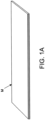
- Figs. 1A and 1B are views illustrating a test specimen (test piece) made of a composite material to which a current measuring method according to a first implementation is applied.
- the composite material to be measured is a fiber reinforced plastic in which resin or plastic is reinforced by conductive fibers, and in this implementation, it is a carbon fiber reinforced plastic (CFRP) containing carbon fibers.
- CFRP carbon fiber reinforced plastic
- the test specimen M is comprised of a composite material in which eight pairs of prepreg sheets (16 prepreg sheets in total) which are composite material sheets soaked or impregnated in non-hardened (non-cured) resin, are laminated and molded into prepreg layers P1-P8.
- Each composite material sheet is formed by laying out plural bundles of carbon fibers in predetermined direction(s).
- the thickness of each prepreg to laminate may be equal to or less than 1 mm (e.g., 0.2 mm).
- prepreg sheet as used herein may also be referred to as "prepreg.”
- the prepreg which constitutes the test specimen M is selected from those corresponding to the actual composite material structure which is considered to be used for an aircraft etc.
- the number of laminated prepreg sheets is not limited to eight layers (or total of 16 sheets), and is arbitrarily selected according to the actual composite material structure.
- partitioning members F1-F7 are disposed in the test specimen M of this implementation between the respective prepreg layers P1-P8, from one end toward the center of the prepreg layers (from the right in Fig. 1B ).
- metal sheets T1-T8 used as electrodes are provided to the end parts of the prepreg layers P1-P8.
- a pair of prepregs Pa and Pb is consisted of two layers among the prepreg layers P1, P2, ....
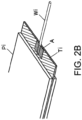
- a metal sheet (T1, T2, ...), such as a copper foil, used as the electrode is disposed between the end parts of each paired prepregs Pa and Pb.
- the partitioning members F1-F7 are folded in half and disposed between the respective prepreg layers P1-P8.
- the prepreg layers P1-P8, the metal sheets T1-T8, and the partitioning members F1-F7 are laminated, and are then pressurized and heated (cured) to mold the test specimen of the composite material in which the end parts of the respective layers are separated and the electrodes are provided.
- the metal sheets T1-T8 used as the electrodes are formed so as to have, for example, a length 11 of an overlapping area with the prepregs is about 4 cm, a length 12 of a projecting area from the ends of the prepregs is about 1 cm. Note that 11 and 12 are not limited to such numerical values.
- the thickness of the metal sheets T1-T8 used as the electrodes may be equal to or less than 70 ⁇ m if the metal sheets are the copper foils.
- the surfaces of the metal sheets T1-T8 are desirable to be grinded or sanded, or etched using acid before molding comprised of pressurizing and heating.
- the metal sheet T1-T8 may have a thickness with a enough strength to sustain a load when leads are coupled thereto, and the usable thicknesses are different depending on the type of metal which constitutes the metal sheets.
- a copper foil is most suitable for a metal sheet, other materials such as an aluminum foil may be used alternatively.
- resin A having conductivity such as conductive silver paste is applied to the surface of an end part of the metal sheet Ti (exposed part) so as to contact an end of a lead Wi.
- the lead Wi can be coupled to the end part of the metal sheet Ti, it is desirable to etch the surface of the end part (exposed part) of the metal sheet Ti by acid, such as sulfuric acid, in order to have a suitable coupling.
- the lead Wi may be coupled by soldering to the surface of the metal sheet Ti which is the electrode part exposed from the end part of the prepreg layer Pi.
- the mold releasing films F1-F7 films as the partitioning members (hereinafter, referred to as "the mold releasing films”) F1-F7 to which an easy-to-remove processing is applied on both sides intervene between the respective layers as a particular method of the mold release processing for the end parts.
- the mold releasing films F1-F7 extend over a predetermined length from one ends of the layers in a longitudinal direction toward the center.
- each of the mold releasing films F1-F7 is folded in half, and then inserted between the respective layers.
- the mold releasing film In a case where the mold releasing film is not folded and is in a sate of a single flat sheet of film, the film may adhere to the surface of the prepreg and the prepregs of the adjacent layers would be difficult to be separated or peeled if the easy-to-remove processing is unevenly done. Therefore, "folding in half" is to prevent this inconvenience.
- the mold releasing film is not limited to being folded in half, but may be the single flat sheet of film without being folded.
- the mold releasing film is desirable to be made of insulating material having heat resistance, for example, Kapton ® which is one of polyimide.
- the easy-to-remove processing applied to the surface of the mold releasing film is, for example, an application of Frekote ® as a mold releasing agent.
- the mold releasing agent to apply is not limited to Frekote ® but may be an insulating material having heat resistance.
- the partitioning member is not limited to the mold releasing film but may also be made of an insulating material such as silicone rubber, or may also be a metal sheet, etc. applied with a mold releasing agent to the surfaces thereof. Further, the partitioning member is not limited to the thin sheet member, but may be a wedge-shaped or plate-shaped resin or metal jig to which the mold releasing agent is applied on the surfaces.
- the test specimen made of CFRP is made by intervening and laminating the partitioning members, such as the mold releasing films, on one sides of the prepreg layers P1-P8 between the respective layers, and heating the prepreg layers P1-P8 in the pressurized state to cure the resin. Then, as described above, the test specimen is completed by coupling the lead Wi for applying measurement current to the electrode part (metal sheet Ti) in the end part of the separating side of each CFRP layer.
- the mold releasing films are removed to use the test specimen for an examination, but the mold releasing films may not be removed and may remain intervened.
- the metal sheets are used as the partitioning members, it is preferred that the metal sheets are removed after the completion of making the test specimen. After the partitioning member is removed, it is preferred to insert insulating members into the respective layers in order to secure the insulation between the respective layers for the measurement.
- the method of making the test specimen is not limited to the method comprised of laminating the plurality of prepregs and curing the resin, but may be any other making methods, such as RTM (Resin Transfer Molding) method.
- RTM Resin Transfer Molding
- VaRTM (Vacuum-assisted Resin Transfer Molding) method which is one kind of the RTM method is a molding method comprised of laying out a plurality of carbon fiber bundles in predetermined direction(s), then injecting liquefied resin into a vacuumed bag film where the carbon fiber bundles are entirely wrapped to impregnate the resin into the fibers, and heating in an oven to cure the resin.
- the plurality of carbon fiber bundles is laid out in the predetermined direction, the plurality of partitioning members such as the mold releasing films is intervened on one side at a predetermined interval, and then the liquefied resin into the vacuumed bag film which wraps entirely is injected.
- the method of making the test specimen may be a technique by cold setting, such as wet layup. In this case, since the partitioning member does not require the heat resistance, a wide variety of materials therefor can be used.
- the process of forming the electrodes by the grinding or sanding processing etc. is not necessary because the composite material is molded in the state where the metal sheet which serves as the electrode is joined to the end part of each CFRP layer in advance. Therefore, there are advantages, such as a suitable reproducibility, a fully-lowered contact resistance, and a small variation of the contact resistance.
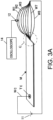
- Figs. 3A to 3C schematically illustrate the current measuring device which uses the test specimen M as an object to be measured.
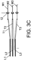
- the current measuring devices include a direct current (DC) power supply 11, Rogowski coil(s) 12t which detect currents flowing through the leads W1-W8 coupled to the end parts of the respective CFRP layers L1-L8 of the test specimen, and an oscilloscope 14 coupled to the Rogowski coil(s) 12t.
- DC direct current
- Rogowski coil(s) 12t which detect currents flowing through the leads W1-W8 coupled to the end parts of the respective CFRP layers L1-L8 of the test specimen
- an oscilloscope 14 coupled to the Rogowski coil(s) 12t.
- a current waveform which imitates a thunderstrike current e.g., a waveform based on the standard specs of the thunderstrike waveform for an aircraft: SAE ARP 5412
- SAE ARP 5412 a current waveform which imitates a thunderstrike current
- Fig. 3A illustrates one of the current measuring devices which measures the current flowing through each CFRP layer Li of the test specimen M.
- the current measuring device sequentially measures the currents while changing a target lead where the corresponding Rogowski coil 12t is placed.
- Fig. 3B illustrates another current measuring device which simultaneously measures the currents flowing through all the CFRP layers L1-L8 of the test specimen M, and the Rogowski coils 12t are disposed on the leads W1-W8, respectively.
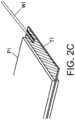
- Fig. 3C illustrates an enlarged view of a portion surrounded by dashed dotted circles C in Figs. 3A and 3B , and the leads W1, W2, W3, ... are coupled to the electrodes (metal sheets) T1, T2, T3, ... in the end parts of the CFRP layer L1, L2, L3, ... which are separated from each other.
- the Rogowski coils are annular coils which can measure large current.
- the Rogowski coils are disposed so as to surround measurement parts and are measurable of the currents based on voltages induced at both ends of the coils.
- the elements for current detection are not limited to the Rogowski coils, but may be any other current sensors, or resistance elements may be coupled to the leads W1-W8 in series and voltages caused between both terminals may be measured to calculate the currents.
- a constant voltage e.g., 5V
- a DC power supply 11v which can change the applied voltage is used in order to measure the current while adjusting the applied voltage so that the current values flowing through the entire target test specimen M are identical among the target test specimen M.
- a common electrode Tc is formed on a surface of the test specimen M in an opposite end part from the separating side, and a common lead Wc is coupled to the common electrode Tc.
- a method of coupling the common lead Wc may be comprised of sanding a part of the surface of the test specimen M (the part of "Tc"), bringing one end of the lead Wc into contact with the sanded part, applying conductive silver paste to the contact part, and heating the silver paste to be sintered.
- the electrode Tc may also be formed by plating after the sanding.
- a Rogowski coil 12t and an ammeter 13t which detect current flowing through the entire test specimen M may be provided, and voltage of the variable DC power supply 11v may be controlled so that the current measured by the ammeter 13t approaches a predetermined value.
- the conventional current measuring methods cannot derive a ratio of the currents flowing through the respective layers of the composite material (current distribution of the material in thickness directions), the ratio of the currents flowing through the respective layers can be derived if the test specimen as described in this implementation is used. Therefore, the current distribution of the composite material, which is actually planned to be used, in the thickness directions at the time of a thunderstrike can be estimated based on the current measuring result.
- a metal part called a fastener may be used in actual aircrafts for coupling the composite material.
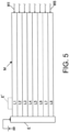
- the current distribution with the fastener may also be demanded to be known in advance. Therefore, for example, as illustrated in Fig. 4 , an electrode E as a conductive member which penetrates all the CFRP layers L1-L8 may be provided to apply current to the electrode E and measure currents flowing through the respective layers.
- the electrode E is attached to an end face of the test specimen M opposite from the layer separating side to apply current to the electrode E and measure currents flowing through the respective layers. Note that, as illustrated in Fig.
- a dashed line E' illustrates one example of an electrode to which current is applied from the surface of the test specimen M similar to one illustrated in Figs. 3A to 3C .
- a test specimen provided with a fastener at an intermediate part thereof may be created to measure a distribution of currents flowing through the respective layers in the case where the fastener exists.
- test specimen M has the strip shape, it may be formed in other shapes, such as a rectangular shape.
- common lead and the individual leads (W1-W8) to the test specimen M are coupled to the opposite ends of the test specimen M, they may be coupled to other locations of the test specimen M.
- the common lead may be coupled to a center part of the test specimen M, or the CFRP layers are peeled in end parts of a plurality of sides and individual leads are coupled to the end parts, respectively.
- the mold releasing films are used for peeling the CFRP layers from each other, but any other structure may be applicable, and, for example, the CFRP layers may be peeled by using a jig after the test specimen M is molded.
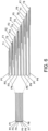
- Fig. 6 is a view illustrating a test specimen (test piece) made of a composite material according to a second implementation of the present disclosure.
- the composite material of this implementation is a fiber reinforced plastic, such as a carbon fiber reinforced plastic (CFRP), similar to the first implementation.
- CFRP carbon fiber reinforced plastic
- a plurality of laminated prepregs P1-P8 has different lengths so that one ends of the prepregs on the electrode formed side are offset (right side in Fig. 6 ). The other ends of the prepregs are aligned (left side in Fig. 6 ).
- each prepreg layer constituting the test specimen is comprised of two prepregs in the first implementation
- each of the prepreg layers P1-P8 is comprised of a single sheet of prepreg in the second implementation.
- the offset amounts may be selected from 5 mm to 50 mm, for example.
- metal sheets T1-T8 such as copper foils used as electrodes are joined to lower surfaces of end parts of the respective prepregs P1-P8 on the electrode formed side, and mold releasing films F1-F7 are sandwiched between the metal sheets T1-T7 and the end parts of the prepregs P2-P8, respectively.
- the laminated body is pressurized and heated to mold the test specimen made of the composite material in which the end parts of the layers are separated and the electrodes are formed.
- each mold releasing film is not limited to being folded in half, but it may be a single flat sheet without being folded.
- the thickness of each layer of the prepregs P1-P8 may be equal to or less than 1 mm (e.g., 0.2 mm). Further, any directions of the carbon fibers in the respective layers of the prepregs P1-P8 can be selected and, for example, directions corresponding to the actual structure of the composite material which are considered to be used for an aircraft etc. are selected.
- any numbers of prepregs may be laminated and, for example, the number corresponding to the actual structure of the composite material is selected.
- a current measuring method for the test specimen (test piece) comprised of the composite material according to the second implementation is the same as the first implementation. Therefore, redundant description is herein omitted.
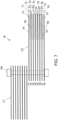
- Fig. 7 is a view illustrating a test specimen (test piece) made of a composite material according to a third implementation of the present disclosure.
- the composite material of this implementation is a fiber reinforced plastic, such as a carbon fiber reinforced plastic (CFRP), similar to the first implementation.
- the test specimen M of this implementation is formed by laying up two composite material plates C1 and C2 so that end parts thereof are overlapped, and coupling the composite material plates with a metal fastener FN.
- Each of the composite material plates C1 and C2 are formed by laminating a plurality of prepregs.
- a method of forming an electrode part is the same as the first and second implementations, and is comprised of intervening metal sheets T1-T8 and mold releasing films F1-F7 between respective prepregs P1-P8.
- the mold releasing films are not limited to being folded in half.
- Figs. 8A and 8B illustrate the entire structure of the test specimen (test piece) and a method of measuring current of the test specimen, according to the third implementation.
- the test specimen of this implementation is formed by laying up two strip-shaped composite material plates C1 and C2 so that their end parts are overlapped, and coupling the composite material plates C1 and C2 with the metal fastener FN.
- the other end of the composite material plate C2 (right-side end in Figs. 8A and 8B ) which is opposite from the coupled side is separated in layers by molding which uses mold releasing films etc. as described with reference to Fig. 7 , only by a predetermined length D.
- the mold release processing for layers is not applied to the composite material plate C1.
- An electrode 10 as a current applying part is formed on the surface of an end part (left-side part in Figs. 8A and 8B ) of the composite material plate C1 opposite from the coupled side by partially sanding, applying silver paste, and sintering or plating, similar to the above-described implementation.
- the electrode 10 is not limited to be one formed on the surface of the composite material plate C1.
- an electrode pin including a fastener which penetrates the composite material plate C1 may be provided, or a plate-shaped electrode which entirely contacts an end face of the composite material plate C1 opposite from the coupled side may be provided.
- processing conditions includes parameters, such as types, rotating speeds, feed rates of tools, such as a drill bit, a drilling machine, used for forming holes.
- the currents flowing through the respective layers of the composite material can be measured and, thus, it is possible to obtain the key to solve the propagation mechanism of the currents in directions including the off-plate directions, and find out the countermeasures against thunderstrikes and short-circuits.
- the contact resistance in the electrode parts can be lowered and the variation thereof can be reduced, homogeneous current can be applied from the electrode parts, and the currents flowing through the respective layers of the composite material can be measured more accurately.
- the present disclosure is not limited to the shape, but may be complicate shapes for typical structures of the composite material. Further, as illustrated in the figure by the dashed lines, a fastener may be provided at an intermediate position of the composite material plate.
- the electrode part 10 is illustrated as, but not limited to the current applying part in the above-described implementation.
- the current applying part may broadly include a portion where current is applied, and in an extreme sense, no processing may be applied to the surface of the composite material plate C1. For example, when carrying out a thunderstrike examination, the current measuring of the present disclosure can be performed by applying a discharge current onto the composite material plate C1 where no electrode part is particularly formed.
- the present disclosure is not limited to the implementations described above but may suitably be changed or modified without departing from the scope of the present disclosure.
- the fiber directions of the test specimen M may be the same for all the layers in the above-described implementation, the test specimen may have laminated layers which have different fiber directions alternately by 90 degrees, or the test specimen may have four layers which have different fiber directions respectively by 45 degrees. Further, the number of laminations is not limited to the eight layers.
- the pretreatment performed to the metal sheets before molding may be determined according to the type of metal to be used which constitutes the metal sheets, and sanding and/or etching suitable for the metal may be applied.
- the etching agent used for the etching before coupling the lead to the electrode may be determined also according to the type of metal which constitutes the metal sheets, and is not limited to sulfuric acid.
- the fiber reinforced plastic in which the resin is reinforced with the conductive fibers is used as the composite material in the above-described implementation, composite materials in whose fibers are nonconductive and resin is conductive (i.e., a conductive resin or a resin where conductive material(s) are kneaded or mixed) may also be used. Further, composite materials which are comprised of conductive fibers and conductive resin may also be used.
- the present invention also relates to the following aspects.
Landscapes
- Engineering & Computer Science (AREA)
- Textile Engineering (AREA)
- Ceramic Engineering (AREA)
- Physics & Mathematics (AREA)
- Fluid Mechanics (AREA)
- Laminated Bodies (AREA)
- Investigating Or Analyzing Materials By The Use Of Electric Means (AREA)
- Casting Or Compression Moulding Of Plastics Or The Like (AREA)
Applications Claiming Priority (2)
| Application Number | Priority Date | Filing Date | Title |
|---|---|---|---|
| JP2015063641A JP6034910B2 (ja) | 2015-03-26 | 2015-03-26 | 複合材及びその製造方法 |
| EP16159589.7A EP3072678B1 (fr) | 2015-03-26 | 2016-03-10 | Matériau composite et son procédé de fabrication |
Related Parent Applications (2)
| Application Number | Title | Priority Date | Filing Date |
|---|---|---|---|
| EP16159589.7A Division EP3072678B1 (fr) | 2015-03-26 | 2016-03-10 | Matériau composite et son procédé de fabrication |
| EP16159589.7A Division-Into EP3072678B1 (fr) | 2015-03-26 | 2016-03-10 | Matériau composite et son procédé de fabrication |
Publications (2)
| Publication Number | Publication Date |
|---|---|
| EP4257352A2 true EP4257352A2 (fr) | 2023-10-11 |
| EP4257352A3 EP4257352A3 (fr) | 2023-11-22 |
Family
ID=55913437
Family Applications (2)
| Application Number | Title | Priority Date | Filing Date |
|---|---|---|---|
| EP16159589.7A Active EP3072678B1 (fr) | 2015-03-26 | 2016-03-10 | Matériau composite et son procédé de fabrication |
| EP23183467.2A Pending EP4257352A3 (fr) | 2015-03-26 | 2016-03-10 | Matériau composite et son procédé de fabrication |
Family Applications Before (1)
| Application Number | Title | Priority Date | Filing Date |
|---|---|---|---|
| EP16159589.7A Active EP3072678B1 (fr) | 2015-03-26 | 2016-03-10 | Matériau composite et son procédé de fabrication |
Country Status (3)
| Country | Link |
|---|---|
| US (1) | US9827743B2 (fr) |
| EP (2) | EP3072678B1 (fr) |
| JP (1) | JP6034910B2 (fr) |
Families Citing this family (3)
| Publication number | Priority date | Publication date | Assignee | Title |
|---|---|---|---|---|
| US11007765B2 (en) * | 2018-03-02 | 2021-05-18 | The Boeing Company | Edge delamination methods and systems |
| CN108422684B (zh) * | 2018-05-04 | 2023-11-03 | 江苏美龙航空部件有限公司 | 大尺寸复合材料罩体或锥体零件精准成型模具及制造方法 |
| JP7374566B2 (ja) | 2020-07-06 | 2023-11-07 | 矢崎総業株式会社 | 複合材構造及び複合材構造製造方法 |
Citations (3)
| Publication number | Priority date | Publication date | Assignee | Title |
|---|---|---|---|---|
| JP2013050306A (ja) | 2011-08-30 | 2013-03-14 | Fuji Heavy Ind Ltd | 局所放電の可視化試験法及び当該可視化試験法に用いられる供試体の製造方法 |
| JP2013053858A (ja) | 2011-09-01 | 2013-03-21 | Fuji Heavy Ind Ltd | 複合材の電気特性測定装置及び電気特性測定方法 |
| JP2014172183A (ja) | 2013-03-06 | 2014-09-22 | Jx Nippon Mining & Metals Corp | キャリア付銅箔、プリント配線板、プリント回路板、銅張積層板、及びプリント配線板の製造方法 |
Family Cites Families (7)
| Publication number | Priority date | Publication date | Assignee | Title |
|---|---|---|---|---|
| JPH07102621B2 (ja) * | 1991-12-16 | 1995-11-08 | 哲士 中村 | Frpとそのfrpの非破壊検査装置 |
| JP4562295B2 (ja) * | 2001-01-29 | 2010-10-13 | 富士重工業株式会社 | 複合材および複合材の損傷制御方法 |
| US7735906B2 (en) * | 2007-09-28 | 2010-06-15 | Zephyros, Inc. | Reinforcement system for an automotive vehicle |
| US20110089958A1 (en) | 2009-10-19 | 2011-04-21 | Applied Nanostructured Solutions, Llc | Damage-sensing composite structures |
| JP5768838B2 (ja) * | 2013-06-17 | 2015-08-26 | トヨタ自動車株式会社 | 車両の骨格構造 |
| JP5860010B2 (ja) | 2013-08-29 | 2016-02-16 | 富士重工業株式会社 | 電流測定装置及び電流測定方法 |
| JP5878963B2 (ja) | 2013-11-18 | 2016-03-08 | 富士重工業株式会社 | 供試体及び電流測定方法 |
-
2015
- 2015-03-26 JP JP2015063641A patent/JP6034910B2/ja active Active
-
2016
- 2016-03-09 US US15/065,527 patent/US9827743B2/en active Active
- 2016-03-10 EP EP16159589.7A patent/EP3072678B1/fr active Active
- 2016-03-10 EP EP23183467.2A patent/EP4257352A3/fr active Pending
Patent Citations (3)
| Publication number | Priority date | Publication date | Assignee | Title |
|---|---|---|---|---|
| JP2013050306A (ja) | 2011-08-30 | 2013-03-14 | Fuji Heavy Ind Ltd | 局所放電の可視化試験法及び当該可視化試験法に用いられる供試体の製造方法 |
| JP2013053858A (ja) | 2011-09-01 | 2013-03-21 | Fuji Heavy Ind Ltd | 複合材の電気特性測定装置及び電気特性測定方法 |
| JP2014172183A (ja) | 2013-03-06 | 2014-09-22 | Jx Nippon Mining & Metals Corp | キャリア付銅箔、プリント配線板、プリント回路板、銅張積層板、及びプリント配線板の製造方法 |
Also Published As
| Publication number | Publication date |
|---|---|
| JP2016183885A (ja) | 2016-10-20 |
| US9827743B2 (en) | 2017-11-28 |
| US20160279903A1 (en) | 2016-09-29 |
| EP3072678A1 (fr) | 2016-09-28 |
| JP6034910B2 (ja) | 2016-11-30 |
| EP4257352A3 (fr) | 2023-11-22 |
| EP3072678B1 (fr) | 2023-08-16 |
Similar Documents
| Publication | Publication Date | Title |
|---|---|---|
| US9575097B2 (en) | Specimen and current measuring method | |
| Todoroki et al. | Piezoresistivity of unidirectional carbon/epoxy composites for multiaxial loading | |
| Athanasopoulos et al. | Prediction and experimental validation of the electrical conductivity of dry carbon fiber unidirectional layers | |
| Khan et al. | Experimental electrical characterisation of carbon fibre composites for use in future aircraft applications | |
| EP3072678B1 (fr) | Matériau composite et son procédé de fabrication | |
| KR102258676B1 (ko) | 고체 전지용 전극 및 고체 전지 | |
| Todoroki | Electric current analysis of CFRP using perfect fluid potential flow | |
| Bensaid et al. | Electromagnetic and thermal behaviors of multilayer anisotropic composite materials | |
| Wang et al. | Usage of conductive polymer composite as the object film of eddy current gap sensor | |
| CA2883719C (fr) | Structures composites ayant des lignes de contact presentant une conductivite electrique appariee | |
| Fukuda | Processing of carbon fiber reinforced plastics by means of Joule heating | |
| EP4286830B1 (fr) | Procédé d'évaluation d'adhérence de séparateur | |
| CN108181029A (zh) | 碳纳米纸传感器多方向监测纤维增强复合材料应变的方法 | |
| Chen et al. | Electrical and thermal behaviour of Z-pin reinforced carbon-fibre composite laminates under fault currents | |
| Laudani et al. | Estimation of contact resistivity in lightning protection equipotential bonding joints of wind turbine blades | |
| EP4635017B1 (fr) | Procédé amélioré de fabrication d'empilements de cellules par activation thermique uniforme d'un adhésif | |
| CN108387616A (zh) | 用于智能张拉的frp无损多电极传感结构及cfrp筋的制作方法 | |
| Mounkaila et al. | Modelling the electrical behaviour of carbon/epoxy composites and monitoring changes in their microstructure during oven and autoclave curing using electrical impedancemetry | |
| Sun et al. | Eddy current Sensing-Enabled smart composite Bolts: Fabrication and Self-Diagnosis capabilities for Hole-Edge damage monitoring | |
| EP4238743B1 (fr) | Procédé de liaison de deux composants composites à fibres les uns avec les autres pour former une structure composite à fibres | |
| Gasco et al. | Hybrid Thin Film Lithium Ion-Graphite Composite Battery Laminates: An Experimental Quasi-static Characterization | |
| Gharghabi et al. | Investigating the Composite/Metal Interface and its Influence on the Electrical Resistance Measurement | |
| Phartiyal et al. | Electrical Resistance Tomography (ERT) applied to Epoxy composites | |
| Benson et al. | Improved capacitive stress transducers for high-field superconducting magnets | |
| Lowe | Toward the Electrical Characterization of Carbon Fiber Reinforced Polymer (CFRP) Composites. |
Legal Events
| Date | Code | Title | Description |
|---|---|---|---|
| PUAI | Public reference made under article 153(3) epc to a published international application that has entered the european phase |
Free format text: ORIGINAL CODE: 0009012 |
|
| STAA | Information on the status of an ep patent application or granted ep patent |
Free format text: STATUS: THE APPLICATION HAS BEEN PUBLISHED |
|
| AC | Divisional application: reference to earlier application |
Ref document number: 3072678 Country of ref document: EP Kind code of ref document: P |
|
| AK | Designated contracting states |
Kind code of ref document: A2 Designated state(s): AL AT BE BG CH CY CZ DE DK EE ES FI FR GB GR HR HU IE IS IT LI LT LU LV MC MK MT NL NO PL PT RO RS SE SI SK SM TR |
|
| PUAL | Search report despatched |
Free format text: ORIGINAL CODE: 0009013 |
|
| AK | Designated contracting states |
Kind code of ref document: A3 Designated state(s): AL AT BE BG CH CY CZ DE DK EE ES FI FR GB GR HR HU IE IS IT LI LT LU LV MC MK MT NL NO PL PT RO RS SE SI SK SM TR |
|
| RIN1 | Information on inventor provided before grant (corrected) |
Inventor name: KAWASHIMA, AI Inventor name: SEKINE, NAOYUKI Inventor name: FUJITA, HIROYASU |
|
| STAA | Information on the status of an ep patent application or granted ep patent |
Free format text: STATUS: REQUEST FOR EXAMINATION WAS MADE |
|
| 17P | Request for examination filed |
Effective date: 20231218 |
|
| RBV | Designated contracting states (corrected) |
Designated state(s): AL AT BE BG CH CY CZ DE DK EE ES FI FR GB GR HR HU IE IS IT LI LT LU LV MC MK MT NL NO PL PT RO RS SE SI SK SM TR |
|
| STAA | Information on the status of an ep patent application or granted ep patent |
Free format text: STATUS: EXAMINATION IS IN PROGRESS |
|
| 17Q | First examination report despatched |
Effective date: 20260413 |