EP4257738A2 - Vorrichtung uno verfahren zur herstellung von mineralwolle uno mineralwolleprodukt - Google Patents
Vorrichtung uno verfahren zur herstellung von mineralwolle uno mineralwolleprodukt Download PDFInfo
- Publication number
- EP4257738A2 EP4257738A2 EP23194928.0A EP23194928A EP4257738A2 EP 4257738 A2 EP4257738 A2 EP 4257738A2 EP 23194928 A EP23194928 A EP 23194928A EP 4257738 A2 EP4257738 A2 EP 4257738A2
- Authority
- EP
- European Patent Office
- Prior art keywords
- fiberizing
- fibres
- plate
- collection device
- led
- Prior art date
- Legal status (The legal status is an assumption and is not a legal conclusion. Google has not performed a legal analysis and makes no representation as to the accuracy of the status listed.)
- Pending
Links
Images
Classifications
-
- C—CHEMISTRY; METALLURGY
- C03—GLASS; MINERAL OR SLAG WOOL
- C03B—MANUFACTURE, SHAPING, OR SUPPLEMENTARY PROCESSES
- C03B37/00—Manufacture or treatment of flakes, fibres, or filaments from softened glass, minerals, or slags
- C03B37/01—Manufacture of glass fibres or filaments
- C03B37/06—Manufacture of glass fibres or filaments by blasting or blowing molten glass, e.g. for making staple fibres
-
- D—TEXTILES; PAPER
- D04—BRAIDING; LACE-MAKING; KNITTING; TRIMMINGS; NON-WOVEN FABRICS
- D04H—MAKING TEXTILE FABRICS, e.g. FROM FIBRES OR FILAMENTARY MATERIAL; FABRICS MADE BY SUCH PROCESSES OR APPARATUS, e.g. FELTS, NON-WOVEN FABRICS; COTTON-WOOL; WADDING ; NON-WOVEN FABRICS FROM STAPLE FIBRES, FILAMENTS OR YARNS, BONDED WITH AT LEAST ONE WEB-LIKE MATERIAL DURING THEIR CONSOLIDATION
- D04H1/00—Non-woven fabrics formed wholly or mainly of staple fibres or like relatively short fibres
- D04H1/40—Non-woven fabrics formed wholly or mainly of staple fibres or like relatively short fibres from fleeces or layers composed of fibres without existing or potential cohesive properties
- D04H1/42—Non-woven fabrics formed wholly or mainly of staple fibres or like relatively short fibres from fleeces or layers composed of fibres without existing or potential cohesive properties characterised by the use of certain kinds of fibres insofar as this use has no preponderant influence on the consolidation of the fleece
- D04H1/4209—Inorganic fibres
- D04H1/4218—Glass fibres
- D04H1/4226—Glass fibres characterised by the apparatus for manufacturing the glass fleece
-
- C—CHEMISTRY; METALLURGY
- C03—GLASS; MINERAL OR SLAG WOOL
- C03B—MANUFACTURE, SHAPING, OR SUPPLEMENTARY PROCESSES
- C03B37/00—Manufacture or treatment of flakes, fibres, or filaments from softened glass, minerals, or slags
- C03B37/01—Manufacture of glass fibres or filaments
- C03B37/04—Manufacture of glass fibres or filaments by using centrifugal force, e.g. spinning through radial orifices; Construction of the spinner cups therefor
- C03B37/045—Construction of the spinner cups
-
- D—TEXTILES; PAPER
- D04—BRAIDING; LACE-MAKING; KNITTING; TRIMMINGS; NON-WOVEN FABRICS
- D04H—MAKING TEXTILE FABRICS, e.g. FROM FIBRES OR FILAMENTARY MATERIAL; FABRICS MADE BY SUCH PROCESSES OR APPARATUS, e.g. FELTS, NON-WOVEN FABRICS; COTTON-WOOL; WADDING ; NON-WOVEN FABRICS FROM STAPLE FIBRES, FILAMENTS OR YARNS, BONDED WITH AT LEAST ONE WEB-LIKE MATERIAL DURING THEIR CONSOLIDATION
- D04H1/00—Non-woven fabrics formed wholly or mainly of staple fibres or like relatively short fibres
- D04H1/40—Non-woven fabrics formed wholly or mainly of staple fibres or like relatively short fibres from fleeces or layers composed of fibres without existing or potential cohesive properties
- D04H1/42—Non-woven fabrics formed wholly or mainly of staple fibres or like relatively short fibres from fleeces or layers composed of fibres without existing or potential cohesive properties characterised by the use of certain kinds of fibres insofar as this use has no preponderant influence on the consolidation of the fleece
- D04H1/4209—Inorganic fibres
- D04H1/4218—Glass fibres
-
- C—CHEMISTRY; METALLURGY
- C03—GLASS; MINERAL OR SLAG WOOL
- C03B—MANUFACTURE, SHAPING, OR SUPPLEMENTARY PROCESSES
- C03B37/00—Manufacture or treatment of flakes, fibres, or filaments from softened glass, minerals, or slags
- C03B37/01—Manufacture of glass fibres or filaments
- C03B37/04—Manufacture of glass fibres or filaments by using centrifugal force, e.g. spinning through radial orifices; Construction of the spinner cups therefor
- C03B37/048—Means for attenuating the spun fibres, e.g. blowers for spinner cups
-
- D—TEXTILES; PAPER
- D04—BRAIDING; LACE-MAKING; KNITTING; TRIMMINGS; NON-WOVEN FABRICS
- D04H—MAKING TEXTILE FABRICS, e.g. FROM FIBRES OR FILAMENTARY MATERIAL; FABRICS MADE BY SUCH PROCESSES OR APPARATUS, e.g. FELTS, NON-WOVEN FABRICS; COTTON-WOOL; WADDING ; NON-WOVEN FABRICS FROM STAPLE FIBRES, FILAMENTS OR YARNS, BONDED WITH AT LEAST ONE WEB-LIKE MATERIAL DURING THEIR CONSOLIDATION
- D04H1/00—Non-woven fabrics formed wholly or mainly of staple fibres or like relatively short fibres
- D04H1/70—Non-woven fabrics formed wholly or mainly of staple fibres or like relatively short fibres characterised by the method of forming fleeces or layers, e.g. reorientation of fibres
- D04H1/72—Non-woven fabrics formed wholly or mainly of staple fibres or like relatively short fibres characterised by the method of forming fleeces or layers, e.g. reorientation of fibres the fibres being randomly arranged
- D04H1/732—Non-woven fabrics formed wholly or mainly of staple fibres or like relatively short fibres characterised by the method of forming fleeces or layers, e.g. reorientation of fibres the fibres being randomly arranged by fluid current, e.g. air-lay
Definitions
- the present invention relates to an apparatus for manufacturing mineral wool according to the preamble of independent claim 1.
- the invention further relates to a method for manufacturing mineral wool according to the preamble of independent claim 13.
- Such mineral wool manufacturing lines are implemented with various configurations.
- mineral wool rock wool and glass wool
- the raw material is melted in a melting furnace and led into a fiberizing device, from which it is brought into the collecting apparatus.
- the manufacture of rock wool typically includes a collection chamber for the fibres formed, and means for collecting the fibres into a fibre mat or web.
- a fibre mat or web which is often called a primary mat, is then brought into the pendulum apparatus, in which is formed a secondary mat of the desired thickness.
- the fiberizing apparatus is typically a plate rotationally arranged around an axis, to the peripheral edge of which plate are arranged numerous small-diameter holes.
- the number of holes can be even tens of thousands and their diagonal can be, for example, in the range of 0.5 mm - 1 mm.
- the molten material led onto the plate pushes through the holes under the influence of centrifugal force, forming fibres.
- a blowing medium oriented substantially parallel with the axis of rotation from above to below, which can be, for example, heated air. This blowing causes the fibres to orientate downwards and to stretch, thus thinning them.
- the fibres are led by the blowing medium to a transportation base passing the blowing medium through, onto which base the fibres are settled into a mat-like or a web-like product to be brought for further processing.
- a fiberizing plate is typically used in the manufacture of glass wool.
- Such a fiberizing plate is presented, for example, in US2991507 .
- shots non-fiberized material
- the object of the present invention is to provide a solution, with which the creation of this shot can be effectively prevented and, at the same time, to provide an adequately high production output as well as high-grade and homogenous product quality.
- the apparatus according to the invention is characterized by the features presented in the characterizing part of independent claim 1.
- the method according to the invention is, in turn, characterized by the features presented in the characterizing part of independent claim 13.
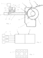
- Reference numeral 1 in Fig. 1 denotes a melting furnace, from which the molten material is led along a trough 2 into a fiberizing device 3.
- the fiberizing device 3 is equipped with a blower 4, which produces a flow 17 of blowing air, which transports the fibres 12 formed by the fiberizing device into the channel 5 and further into the collection device 6.
- the collection device 6 has a collection chamber 7 and collector elements 8, which, in this embodiment, comprise a collection drum 9 equipped with a perforated peripheral surface, inside which is a suction box 10. The blowing air moves through the holes of the drum 9 into the suction box and further away from the collection apparatus.
- the collection chamber can as such be according to known art, or it can differ from known art.
- the feeding of binder is not shown in the figure.
- the collection device can be a foraminous or perforated belt conveyor having suction boxes inside the belt loop.
- the fiberizing device 3 comprises, rotating around a vertical axis 15, a cup-like plate 13, on the periphery of which are numerous small holes 14, through which the molten mass moves under the influence of centrifugal force forming fibres 12, which are stretched around the plate by vertically led blowing air 16, annularly surrounding the plate.
- binder and other necessary chemicals can be fed.
- Such a fiberizing plate and the production of blowing air, surrounding it annularly, in the manufacture of glass wool is prior known to the skilled person in the art, for example, from US4759974 .
- the advantage in using such a fiberizing plate is that the majority of the mass can be fiberized.
- the disadvantage is that through one fiberizing device can be fed only approx.
- molten mass per hour 400-500 kg molten mass per hour, which is significantly less than in solutions implemented with spinner discs, in which the fed amount of molten mass can be, for example, 5000-7000 kg per hour.
- a relatively small-diameter, horizontal channel 5 leading to the collection device the length of which channel can be several metres, for example, in the range of approx. 1 m - approx. 10 m.
- a blower 4 which creates a horizontal air flow in the channel 5 directing the fibres 12, oriented downwards by the vertical blowing air 16 in the fiberizing device, horizontally along the channel 5 towards the collection device 6.
- this channel solution it is possible to place several fiberizing devices 3 to feed one collection device 6, wherein the production output can be increased to a desired level.
- the fiberizing devices can be placed at different height levels with each other and at different horizontal distance from the collection device 6, wherein only the channels 5 need to be adapted to the inlet port of the collection device.
- the channels 5 do not need to all be the same shape or size, and their location in relation to the collection apparatus can also be modified.
- Fig. 2 shows as a schematic illustration viewed from above of one placement of the fiberizing devices 3 in relation to each other, as well as in relation to the collection chamber 7 and the collector elements 8.
- Fig. 3 shows schematically an example of one manner of placing the channels 5 in the mouth of the collection device 6 as viewed from the direction of the collection drum 9.
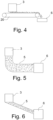
- Fig. 4 shows a schematic illustration of the apparatus wherein the conveying device comprises a belt 20 on which the fibres are deposited.
- the belt can be provided with suction boxes inside the belt loop to assist depositing of the fibres on the certain portion of upper run of the belt.
- the belt is preferably without any suction means in the discharging area of the belt loop or there can be blower means for directing an air flow from inside the belt loop through the belt in the discharging area of the belt 20 to assist releasing of the fibres.
- Fig. 5 shows a schematic illustration of the apparatus wherein the conveying device 5 comprises a curved channel 5 through which the fibres are transported from a fiberizing device 3 to a collection device 6 by means of the blowing air directed vertically downwards around the fiberizing plate and/or by means of suction means arranged in the channel in the vicinity of the collection device.
- the conveying device 5 comprises a curved channel 5 through which the fibres are transported from a fiberizing device 3 to a collection device 6 by means of the blowing air directed vertically downwards around the fiberizing plate and/or by means of suction means arranged in the channel in the vicinity of the collection device.
- Fig. 6 shows a schematic illustration of the apparatus wherein the conveying device 5 comprises an inclined channel 5 through which the fibres are transported from a fiberizing device 3 to a collection device by means of the blowing air directed vertically downwards around the fiberizing plate and/or by means of suction means arranged in the channel in the vicinity of the collection device.
- the conveying device 5 comprises an inclined channel 5 through which the fibres are transported from a fiberizing device 3 to a collection device by means of the blowing air directed vertically downwards around the fiberizing plate and/or by means of suction means arranged in the channel in the vicinity of the collection device.
- One or more fiberizing plates can be equipped with perforations of different size in relation to the other fiberizing plates, wherein different fiberizing plates can be used to produce fibres of different size. Furthermore, different fiberizing plates can be used to produce different fiberizing parameters, such as, for example, the rotation speed of the plate, the feeding rate of the molten material and/or the flow rate of the vertical blowing air, to vary in a desired manner the characteristics of the intermediate product and/or final product to be manufactured by the apparatus.
- the fiberizing plates can be similar to or different from each other, i.e. their dimensions, such as, for example, the diameters of the fiberizing plates may differ from each other, and the fiberizing plates may also differ in their design (for example, the height and shape of the edges of the fiberizing plate).
- the method according to the invention enables the manufacture of a mineral wool product having the desired tensile strength characteristics, i.e. the transverse tensile strength of which is greater than the linear tensile strength.
- An apparatus for manufacturing mineral wool including means (1) for producing molten mineral material, at least one fiberizing device (3) for forming fibres, into which fiberizing device the molten mineral material is fed (2) and by which fibres (12) are formed, the fiberizing device (3) comprising, rotationally arranged around a vertical axis (15), at least one fiberizing plate (13) having a vertical peripheral edge, into which are formed numerous small-sized holes (14), through which the molten material is led by centrifugal force to form fibres (12), wherein to the fiberizing device (3) are arranged elements to produce a vertical flow of blowing medium (16) to be led around the fiberizing plate (13), the flow causing the fibres (12) to turn downwards and, at the same time, to thin, as well as a collection device (6) arranged downstream the fiberizing device (3), into which the formed fibres (12) are led and collected into a mat-like material, characterized in that the apparatus includes at least two fiberizing devices (3), which are placed at different height levels with each other and/or at
- Statement 2 An apparatus according to statement 1, characterized in that the conveying device comprises a horizontal or inclined channel (5) located between the fiberizing plate and collection device (6).
- Statement 3 An apparatus according to statement 2, characterized in that the channel (5) is straight or curved.
- Statement 4 An apparatus according to statement 1, characterized in that the conveying device comprises a belt.
- Statement 5 An apparatus according to any of statements 1 to 4, characterized in that the conveying device comprises air producing means and/or suction means for transporting fibres to the collection device (6).
- Statement 6 An apparatus according to any of statements 1 to 5, characterized in that the collection device (6) has a collection chamber (7) and collector elements (8), which comprise a collection drum (9) equipped with a perforated peripheral surface, inside which is a suction box (10), onto which drum the fibres are collected into a primary mat or web.
- collector elements (8) which comprise a collection drum (9) equipped with a perforated peripheral surface, inside which is a suction box (10), onto which drum the fibres are collected into a primary mat or web.
- Statement 7 An apparatus according to statements 2 or 3, characterized in that the length of the channel (5) is in the range of 1-10 m.
- Statement 8 An apparatus according to any one of statements 1 to 7, characterized in that the diameter of the holes (14) on the periphery of the fiberizing plate (13) is in the range of approx. 0.3 mm - approx. 2 mm, preferably approx. 0.5 mm - approx. 1 mm.
- Statement 9 An apparatus according to any one of statements 1 to 8, characterized in that at least one fiberizing plate (13) has holes (14) of different size in relation to the holes of at least one other fiberizing plate for forming fibres of different thicknesses by different fiberizing plates.
- Statement 11 An apparatus according to any one of statements 1 to 10, characterized in that the fiberizing plates are similar to each other.
- Statement 12 An apparatus according to any one of statements 1 to 10, characterized in that the fiberizing plates are different from each other.
- Statement 13 - A method for manufacturing mineral wool the method using an apparatus, which includes means (1) for producing molten mineral material, at least one fiberizing device (3) for forming fibres, into which fiberizing device the molten mineral material is fed and by which fibres (12) are formed, the fiberizing device (3) comprising, rotationally arranged around a vertical axis (15), at least one fiberizing plate (13) having a vertical peripheral edge, into which are formed numerous small- sized holes (14), through which the molten material is led by centrifugal force to form fibres (12), wherein into the fiberizing device (3) are arranged elements to produce an annular flow of blowing medium (16) directed vertically downwards around the fiberizing plate (13), the flow causing the fibres (12) to turn downwards and to thin, as well as a collection device (6) arranged downstream the fiberizing device (3), into which the formed fibres (12) are led and collected into a mat-like material, characterized in that, in the method, at least two fiberizing devices (3) are arranged to feed fibres into a common collection
Landscapes
- Engineering & Computer Science (AREA)
- Chemical & Material Sciences (AREA)
- Manufacturing & Machinery (AREA)
- General Life Sciences & Earth Sciences (AREA)
- Textile Engineering (AREA)
- Life Sciences & Earth Sciences (AREA)
- Inorganic Chemistry (AREA)
- Geochemistry & Mineralogy (AREA)
- Materials Engineering (AREA)
- Organic Chemistry (AREA)
- Nonwoven Fabrics (AREA)
- Spinning Methods And Devices For Manufacturing Artificial Fibers (AREA)
- Inorganic Fibers (AREA)
- Manufacture, Treatment Of Glass Fibers (AREA)
- Solid-Sorbent Or Filter-Aiding Compositions (AREA)
Applications Claiming Priority (3)
| Application Number | Priority Date | Filing Date | Title |
|---|---|---|---|
| FI20175788A FI127818B (fi) | 2017-09-01 | 2017-09-01 | Laitteisto ja menetelmä mineraalivillan valmistamiseksi |
| EP18765940.4A EP3676435B8 (de) | 2017-09-01 | 2018-08-28 | Vorrichtung und verfahren zur herstellung von mineralwolle und mineralwolleprodukt |
| PCT/FI2018/050607 WO2019043290A1 (en) | 2017-09-01 | 2018-08-28 | APPARATUS AND METHOD FOR PRODUCING MINERAL WOOL AND MINERAL WOOL PRODUCT |
Related Parent Applications (2)
| Application Number | Title | Priority Date | Filing Date |
|---|---|---|---|
| EP18765940.4A Division-Into EP3676435B8 (de) | 2017-09-01 | 2018-08-28 | Vorrichtung und verfahren zur herstellung von mineralwolle und mineralwolleprodukt |
| EP18765940.4A Division EP3676435B8 (de) | 2017-09-01 | 2018-08-28 | Vorrichtung und verfahren zur herstellung von mineralwolle und mineralwolleprodukt |
Publications (2)
| Publication Number | Publication Date |
|---|---|
| EP4257738A2 true EP4257738A2 (de) | 2023-10-11 |
| EP4257738A3 EP4257738A3 (de) | 2024-01-03 |
Family
ID=63524311
Family Applications (2)
| Application Number | Title | Priority Date | Filing Date |
|---|---|---|---|
| EP18765940.4A Active EP3676435B8 (de) | 2017-09-01 | 2018-08-28 | Vorrichtung und verfahren zur herstellung von mineralwolle und mineralwolleprodukt |
| EP23194928.0A Pending EP4257738A3 (de) | 2017-09-01 | 2018-08-28 | Vorrichtung uno verfahren zur herstellung von mineralwolle uno mineralwolleprodukt |
Family Applications Before (1)
| Application Number | Title | Priority Date | Filing Date |
|---|---|---|---|
| EP18765940.4A Active EP3676435B8 (de) | 2017-09-01 | 2018-08-28 | Vorrichtung und verfahren zur herstellung von mineralwolle und mineralwolleprodukt |
Country Status (8)
| Country | Link |
|---|---|
| US (3) | US11572645B2 (de) |
| EP (2) | EP3676435B8 (de) |
| CN (1) | CN111295470A (de) |
| DK (1) | DK3676435T3 (de) |
| FI (2) | FI127818B (de) |
| PL (1) | PL3676435T3 (de) |
| RU (1) | RU2020112277A (de) |
| WO (1) | WO2019043290A1 (de) |
Families Citing this family (1)
| Publication number | Priority date | Publication date | Assignee | Title |
|---|---|---|---|---|
| CN110791877A (zh) * | 2019-09-17 | 2020-02-14 | 安徽吉曜玻璃微纤有限公司 | 一种以超细玻璃微纤为芯材的真空绝热板及其制备工艺 |
Citations (3)
| Publication number | Priority date | Publication date | Assignee | Title |
|---|---|---|---|---|
| US2991507A (en) | 1956-07-12 | 1961-07-11 | Saint Gobain | Manufacture of fibers from thermoplastic materials such as glass |
| WO1987006631A1 (en) | 1986-04-25 | 1987-11-05 | Oy Partek Ab | A method and device for manufacturing a mineral wool web |
| US4759974A (en) | 1982-04-06 | 1988-07-26 | Isover Saint-Gobain | Glass fiberization |
Family Cites Families (21)
| Publication number | Priority date | Publication date | Assignee | Title |
|---|---|---|---|---|
| US2255227A (en) | 1938-11-10 | 1941-09-09 | United States Gypsum Co | Apparatus for producing mineral wool |
| US2318244A (en) | 1939-08-21 | 1943-05-04 | Owens Corning Fiberglass Corp | Fiberizing mineral substances by centrifuge and blast |
| US2897874A (en) * | 1955-12-16 | 1959-08-04 | Owens Corning Fiberglass Corp | Method and apparatus of forming, processing and assembling fibers |
| US3331669A (en) * | 1963-06-21 | 1967-07-18 | Johns Manville | Method and apparatus for forming mineral wool products |
| US3824086A (en) * | 1972-03-02 | 1974-07-16 | W M Perry | By-pass fiber collection system |
| CA991409A (en) * | 1972-03-21 | 1976-06-22 | Dale Kleist | Method and apparatus for producing and collecting fibers |
| FR2423558A1 (fr) | 1978-04-19 | 1979-11-16 | Saint Gobain | Dispositif pour la fabrication de fibres par etirage au moyen de courants gazeux |
| US4507197A (en) | 1982-08-09 | 1985-03-26 | Jim Walter Corporation | Apparatus and method for producing shot-free mineral wool |
| DE3509426A1 (de) * | 1985-03-15 | 1986-09-18 | Grünzweig + Hartmann und Glasfaser AG, 6700 Ludwigshafen | Einrichtung zur herstellung von mineralfasern aus silikatischen rohstoffen, insbesondere basalt mit einem modularen viskositaetsmodul von mindestens 1,5, nach dem duesenblasverfahren |
| US5523032A (en) * | 1994-12-23 | 1996-06-04 | Owens-Corning Fiberglas Technology, Inc. | Method for fiberizing mineral material with organic material |
| US5955011A (en) * | 1996-10-24 | 1999-09-21 | Johns Manville International, Inc. | Evaporative cooling apparatus and method for a fine fiber production process |
| WO1999051535A1 (en) | 1998-04-06 | 1999-10-14 | Rockwool International A/S | Man-made vitreous fibre batts and their production |
| DE19834963A1 (de) * | 1998-08-03 | 2000-02-17 | Pfleiderer Daemmstofftechnik G | Vorrichtung und Verfahren zur Herstellung von Mineralwollevlies |
| US20040132371A1 (en) | 1998-08-03 | 2004-07-08 | Pfleiderer Dammstofftechnik International Gmbh & Co. | Method and device for producing a mineral wool nonwoven fabric |
| FI121784B (sv) | 2004-12-31 | 2011-04-15 | Paroc Oy Ab | Arrangemang och förfarande vid framställning av mineralull samt fibreringsanordning |
| US7514027B2 (en) * | 2005-02-17 | 2009-04-07 | Saint-Gobain Isover | Process for manufacturing products of mineral wool, in particular monolayer and multilayer products |
| FR2928146B1 (fr) * | 2008-02-28 | 2010-02-19 | Saint Gobain Isover | Produit a base de fibres minerales et son procede d'obtention. |
| US8474737B2 (en) | 2010-09-24 | 2013-07-02 | Owens Corning Intellectual Capital, Llc | Rotary forming apparatus |
| US9938712B2 (en) * | 2011-03-30 | 2018-04-10 | Owens Corning Intellectual Capital, Llc | High thermal resistivity insulation material with opacifier uniformly distributed throughout |
| US20140076000A1 (en) | 2012-09-20 | 2014-03-20 | Timothy James Johnson | Apparatus and method for air flow control during manufacture of glass fiber insulation |
| WO2015142294A1 (en) | 2014-03-17 | 2015-09-24 | Izoteh D.O.O. | Collecting chamber and fiber formation method |
-
2017
- 2017-09-01 FI FI20175788A patent/FI127818B/fi active IP Right Grant
-
2018
- 2018-08-28 RU RU2020112277A patent/RU2020112277A/ru unknown
- 2018-08-28 FI FIEP18765940.4T patent/FI3676435T3/fi active
- 2018-08-28 EP EP18765940.4A patent/EP3676435B8/de active Active
- 2018-08-28 US US16/643,330 patent/US11572645B2/en active Active
- 2018-08-28 CN CN201880070676.4A patent/CN111295470A/zh active Pending
- 2018-08-28 DK DK18765940.4T patent/DK3676435T3/da active
- 2018-08-28 EP EP23194928.0A patent/EP4257738A3/de active Pending
- 2018-08-28 PL PL18765940.4T patent/PL3676435T3/pl unknown
- 2018-08-28 WO PCT/FI2018/050607 patent/WO2019043290A1/en not_active Ceased
-
2023
- 2023-01-04 US US18/149,694 patent/US12398496B2/en active Active
-
2024
- 2024-12-16 US US18/981,952 patent/US20250116040A1/en active Pending
Patent Citations (3)
| Publication number | Priority date | Publication date | Assignee | Title |
|---|---|---|---|---|
| US2991507A (en) | 1956-07-12 | 1961-07-11 | Saint Gobain | Manufacture of fibers from thermoplastic materials such as glass |
| US4759974A (en) | 1982-04-06 | 1988-07-26 | Isover Saint-Gobain | Glass fiberization |
| WO1987006631A1 (en) | 1986-04-25 | 1987-11-05 | Oy Partek Ab | A method and device for manufacturing a mineral wool web |
Also Published As
| Publication number | Publication date |
|---|---|
| FI20175788A1 (fi) | 2019-03-02 |
| EP3676435B8 (de) | 2023-12-27 |
| DK3676435T3 (da) | 2023-12-18 |
| EP3676435A1 (de) | 2020-07-08 |
| FI3676435T3 (fi) | 2023-12-15 |
| US12398496B2 (en) | 2025-08-26 |
| US20250116040A1 (en) | 2025-04-10 |
| US20210079572A1 (en) | 2021-03-18 |
| FI127818B (fi) | 2019-03-15 |
| EP3676435B1 (de) | 2023-10-04 |
| CN111295470A (zh) | 2020-06-16 |
| EP4257738A3 (de) | 2024-01-03 |
| RU2020112277A (ru) | 2021-10-01 |
| PL3676435T3 (pl) | 2024-05-06 |
| US11572645B2 (en) | 2023-02-07 |
| US20230183897A1 (en) | 2023-06-15 |
| WO2019043290A1 (en) | 2019-03-07 |
Similar Documents
| Publication | Publication Date | Title |
|---|---|---|
| JP2004532938A (ja) | ミネラルウールを形成するためのプロセス及び装置並びにミネラルウール製品 | |
| WO2007133549A1 (en) | Rotary fiberization process for making glass fibers, an insulation mat, and pipe insulation | |
| US20250116040A1 (en) | Apparatus and method for manufacturing mineral wool as well as a mineral wool product | |
| CN104685119B (zh) | 用于制造隔热和/或隔音产品的设备和方法 | |
| JP5368322B2 (ja) | 繊維状物の集積方法及び集積装置 | |
| US7958752B2 (en) | Method and apparatus for distributing fibrous material | |
| NO140419B (no) | Apparat til fremstilling av mineralull | |
| FI123701B (fi) | Järjestelmä ja menetelmä mineraalikuitujen valmistuksessa | |
| RU2415088C2 (ru) | Способ производства минеральных волокон | |
| JP7049927B2 (ja) | ミネラルウールの製造方法及び装置 | |
| EP1888829B1 (de) | Sammelkammer und verfahren zur herstellung von mineralfasern | |
| FI119381B (fi) | Menetelmä ja järjestelmä mineraalikuitumaton kuljettamiseksi mineraalikuitumaton valmistusprosessissa, sekä järjestelmän käyttö | |
| FI127025B (sv) | Förfarande vid framställning av mineralull | |
| RU2116270C1 (ru) | Способ формирования холста из минерального супертонкого волокна и устройство для его осуществления | |
| JPS5945778B2 (ja) | 連続して帯状の預層ガラス短繊維体を製造する方法 | |
| EP2325362A2 (de) | Verfahren und Zusammenstellung zum Fertigen eines Mineralfasergewebes | |
| CZ222396A3 (en) | Apparatus for producing mineral fibers from silicate melt |
Legal Events
| Date | Code | Title | Description |
|---|---|---|---|
| PUAI | Public reference made under article 153(3) epc to a published international application that has entered the european phase |
Free format text: ORIGINAL CODE: 0009012 |
|
| STAA | Information on the status of an ep patent application or granted ep patent |
Free format text: STATUS: THE APPLICATION HAS BEEN PUBLISHED |
|
| AC | Divisional application: reference to earlier application |
Ref document number: 3676435 Country of ref document: EP Kind code of ref document: P |
|
| AK | Designated contracting states |
Kind code of ref document: A2 Designated state(s): AL AT BE BG CH CY CZ DE DK EE ES FI FR GB GR HR HU IE IS IT LI LT LU LV MC MK MT NL NO PL PT RO RS SE SI SK SM TR |
|
| REG | Reference to a national code |
Ref country code: DE Ref legal event code: R079 Free format text: PREVIOUS MAIN CLASS: D04H0001422600 Ipc: D04H0001420900 |
|
| PUAL | Search report despatched |
Free format text: ORIGINAL CODE: 0009013 |
|
| AK | Designated contracting states |
Kind code of ref document: A3 Designated state(s): AL AT BE BG CH CY CZ DE DK EE ES FI FR GB GR HR HU IE IS IT LI LT LU LV MC MK MT NL NO PL PT RO RS SE SI SK SM TR |
|
| RIC1 | Information provided on ipc code assigned before grant |
Ipc: D04H 1/4226 20120101ALI20231129BHEP Ipc: D04H 1/4218 20120101ALI20231129BHEP Ipc: C03C 13/06 20060101ALI20231129BHEP Ipc: D04H 1/4209 20120101AFI20231129BHEP |
|
| STAA | Information on the status of an ep patent application or granted ep patent |
Free format text: STATUS: REQUEST FOR EXAMINATION WAS MADE |
|
| 17P | Request for examination filed |
Effective date: 20240621 |
|
| RBV | Designated contracting states (corrected) |
Designated state(s): AL AT BE BG CH CY CZ DE DK EE ES FI FR GB GR HR HU IE IS IT LI LT LU LV MC MK MT NL NO PL PT RO RS SE SI SK SM TR |
|
| STAA | Information on the status of an ep patent application or granted ep patent |
Free format text: STATUS: EXAMINATION IS IN PROGRESS |
|
| 17Q | First examination report despatched |
Effective date: 20260115 |